US6329937B1 - Robust data communications using multiple spectral images - Google Patents
Robust data communications using multiple spectral imagesDownload PDFInfo
- Publication number
- US6329937B1 US6329937B1US09/372,332US37233299AUS6329937B1US 6329937 B1US6329937 B1US 6329937B1US 37233299 AUS37233299 AUS 37233299AUS 6329937 B1US6329937 B1US 6329937B1
- Authority
- US
- United States
- Prior art keywords
- signal
- recited
- images
- data transmitter
- filter
- Prior art date
- Legal status (The legal status is an assumption and is not a legal conclusion. Google has not performed a legal analysis and makes no representation as to the accuracy of the status listed.)
- Expired - Lifetime
Links
- 230000003595spectral effectEffects0.000titledescription19
- 238000004891communicationMethods0.000titledescription9
- 238000000034methodMethods0.000claimsabstractdescription14
- 238000012545processingMethods0.000claimsabstractdescription4
- 238000005070samplingMethods0.000claimsdescription14
- 238000007493shaping processMethods0.000claimsdescription7
- 238000001914filtrationMethods0.000claims1
- 230000005540biological transmissionEffects0.000description10
- 238000010586diagramMethods0.000description3
- 238000001228spectrumMethods0.000description3
- 238000013461designMethods0.000description2
- 230000003044adaptive effectEffects0.000description1
- 230000000739chaotic effectEffects0.000description1
- 239000002131composite materialSubstances0.000description1
- 230000036039immunityEffects0.000description1
- 230000002093peripheral effectEffects0.000description1
- 238000011084recoveryMethods0.000description1
- 238000012552reviewMethods0.000description1
- 238000000411transmission spectrumMethods0.000description1
Images


Classifications
- H—ELECTRICITY
- H03—ELECTRONIC CIRCUITRY
- H03M—CODING; DECODING; CODE CONVERSION IN GENERAL
- H03M1/00—Analogue/digital conversion; Digital/analogue conversion
- H03M1/06—Continuously compensating for, or preventing, undesired influence of physical parameters
- H03M1/0617—Continuously compensating for, or preventing, undesired influence of physical parameters characterised by the use of methods or means not specific to a particular type of detrimental influence
- H03M1/0675—Continuously compensating for, or preventing, undesired influence of physical parameters characterised by the use of methods or means not specific to a particular type of detrimental influence using redundancy
- H—ELECTRICITY
- H04—ELECTRIC COMMUNICATION TECHNIQUE
- H04B—TRANSMISSION
- H04B14/00—Transmission systems not characterised by the medium used for transmission
- H04B14/02—Transmission systems not characterised by the medium used for transmission characterised by the use of pulse modulation
- H04B14/04—Transmission systems not characterised by the medium used for transmission characterised by the use of pulse modulation using pulse code modulation
Definitions
- the inventionis directed to the field of communications, and in particular to the field of data communications.
- Data communicationnormally occurs on a network that is optimized for data transmission and is therefore physically adapted to be relatively immune to interference.
- some modern data communication scenariosoverlay existing media and therefore may incorporate physical limitations dictated by the media.
- one method of internetworking home computing or communication devicesis to take advantage of the existing home telephone wiring system, which typically includes a network of wires to virtually every room in the house. This method is described, for example, by the presently active Home Phoneline Network Alliance (HomePNA) special interest group in its current version one (V1.x) standard, and its pending version two (V2.x) standard.
- HomePNAHome Phoneline Network Alliance
- a limitation dictated by the advantageous use of the telephone lines within the home as a data networkis that the telephone lines were not originally put in place to optimize data communications.
- the number and nature of bridge tapsare not readily controlled, as they vary with respect to the number of devices coupled to the network and the length of line associated with each bridge tap.
- a HomePNA systemis preferably functional in a diverse set of environments. The chaotic set of environments within which a HomePNA system may function makes it difficult to configure a single system that will function properly in all, or most, environments.
- each bridge tapgiven the physics associated with the connection of a device to the network and the associated line length, may yield a spectral null within an important part of the transmission spectrum
- bridge tap line lengths of fifteen to thirty-five feetwill yield tap-induced spectral nulls within the 4-10 MHz band of interest.
- specific spectral nullsmay be intentionally created to minimize interference with other communication media, such as ham radios.
- spectral nullsmay create a problem if one of them coincides, in the frequency domain, with a significant portion of a data transmission.
- a decision feedback equalized (DFE)is employed to recognize and correct for the signal loss associated with the transmission of data in a null.
- DFEdecision feedback equalized
- a DFE used in this mannerleads to a complicated system that is difficult to start up (i.e., to converge for data recovery purposes). What is needed is a simplified receiver design that enables successful data transmission in the presence of spectral nulls, and in particular, in the presence of an unknown quantity and position of such nulls.
- multiple images of the same signalare generated at different frequencies to provide coverage over multiple frequency bands.
- the multiple imagesare combined by the sampling of a digital receiver.
- the resulting composite baseband signalis robust in the presence of spectral nulls, such as those created by bridge taps.
- a system based on the inventive conceptis easy to start up and achieves reliable performance in the presence of spectral nulls and single tone interference.
- a data transmitterincludes a digital-to-analog converter adapted to receive an input signal and produce a plurality of images therefrom, each image being displaced from the other images in frequency, and a compensation filter adapted to compensate at least one of the plurality of images to adjust for a loss inherent in the digital-to-analog converter.
- a receiverincludes an analog-to-digital converter adapted to receive a line signal comprising a plurality of frequency diverse images, and to produce a sampled signal representative of a single image therefrom.
- a method of transmitting a signalincludes the steps of creating a plurality of images of a main signal, compensating at least one of the images, and outputting the images.
- a method of receiving a signalincludes the steps of receiving a plurality of images, and processing the plurality of images so that an uncorrupted portion of one image compensates for a corrupted portion of another image.
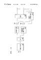
- FIG. 1is a simplified block diagram of a transmitter configured according to the invention
- FIG. 2is an exemplary plot of a real portion of a complex signal existing at an output point of a summer within the transmitter of FIG. 1;
- FIG. 3is an exemplary plot of an output of a digital-to-analog converter within the transmitter of FIG. 1;
- FIG. 4is an exemplary swept spectrum plot of multiple images corresponding to the data of FIG. 3;
- FIG. 5is an exemplary plot of an alternative output of a digital-to-analog converter within the transmitter of FIG. 1;
- FIG. 6is an exemplary plot of yet another alternative output of a digital-to-analog converter within the transmitter of FIG. 1;
- FIG. 7is a simplified block diagram of a receiver configured according to the invention.
- FIG. 8is an exemplary plot of an exemplary signal received by the receiver of FIG. 7;
- FIG. 9is an exemplary plot of a sampled signal produced from the received signal of FIG. 8;
- FIG. 10is an exemplary plot of an alternative signal received by the receiver of FIG. 7;
- FIG. 11is an exemplary plot of a sampled signal produced from the received signal of FIG. 10;
- FIG. 12is an exemplary plot of yet another alternative signal received by the receiver of FIG. 7;
- FIG. 13is an exemplary plot of a sampled signal produced from the received signal of FIG. 12.
- FIG. 14is a simplified block diagram of an alternative receiver configured according to the invention.
- FIG. 1is an exemplary transmitter according to the invention.
- the transmitter of FIG. 1is employed in a HomePNA network, such as within a computer or electronic device communicating via the home phone wires with another device.
- Data symbols 105 and 107representing the information to be transmitted to the other device, are supplied respectively to inphase shaping filter 109 and quadrature shaping filter 111 prior to combining at summer 113 .
- Shaping filters 109 and 111may be, for example, 100% excess bandwidth shaping filters, although tighter excess bandwidths may be employed by one skilled in the art, depending on the application.
- An exemplary symbol rate for data symbols 105 and 107is 2.5 MBaud, although this data rate is provided merely by way of example and not of limitation. In practice, any data rate may be employed according to the invention, and it is expected that higher data rates will be employed in the future.
- the front-end portion of the transmitter of FIG. 1( 109 - 113 ) is representative of a carrier-less amplitude and phase (CAP) complex transmission scheme.
- aspects of the inventionmay be incorporated into a quadrature amplitude modulation (QAM) transmission scheme, in which case a sine modulator and a cosine modulator would respectively be incorporated after the filters 109 and 111 .
- QAMquadrature amplitude modulation
- the attributes and relative merits of CAP and QAMare well known to those of skill in the art, and the determination of the modulation scheme is largely one of design choice, as the inventive concepts can be applied to either scheme.
- FIG. 2is an exemplary plot of the real portion of a complex signal at the output of summer 113 .
- This complex signalis provided to digital-to-analog (D/A) converter 115 , which has a sampling rate, for example, of 7.5 MHz, or three samples per symbol.
- the output of D/A converter 115is shown in FIG. 3 .
- the main signal 301centered at approximately 2.5 MHz is paired with a second image 303 centered at approximately 5 MHz.
- a pair of third and fourth images 305 and 307are respectively centered at approximately 10 and 12.5 MHz, while another pair of fifth and sixth images 309 and 311 are respectively centered at approximately 17.5 and 20 MHz.
- the relative power of the images 301 - 311is shaped by the sampling function of the D/A converter 115 , and an exemplary swept spectrum plot of these images is shown in FIG. 4 .
- the 7.5 MHz sampling rate(T/ 3 ) is merely by way of example, and not of limitation.
- 10 MHz (T/ 4 )which is shown in FIG. 5, or 15 MHz (T/ 6 ), which is shown in FIG. 6, could also be employed.
- the higher sampling ratesmay provide improved performance, with respect to any lower frequency images, but may cause some of the higher frequency images to exist in an undesirable region of the frequency spectrum, where they may be subject to federal regulations.
- the output of D/A converter 115may be input to a filter, such as high pass filter 117 .
- High pass filter 117is particularly useful in the HomePNA environment to remove virtually all energy below a certain level, such as 7 MHz, in order to prevent interference with other lower frequency communications sharing the network, such as Plain Old Telephone Service (POTS), Integrated Services Digital Networks (ISDN), and Asynchronous Digital Subscriber Line (ADSL) services.
- POTSPlain Old Telephone Service
- ISDNIntegrated Services Digital Networks
- ADSLAsynchronous Digital Subscriber Line
- the filter 117eliminates the main signal 301 and the first image 303 .
- the remaining images ( 305 - 311 , etc.)may then be applied to compensation filter 119 , which, in the preferred embodiment, is a sin(x)/x compensation filter to compensate for sin(x)/x loss inherent in digital to analog converter 115 .
- Filter 119is employed to compensate for loss seen by higher order lobes.
- the compensation filter 119has 7 dB of positive slope from 7 MHz to 22 MHz, and is thus effectively applied to the third through sixth images 305 . 311 .
- a receiver according to the inventioncoupled, for example, to a receiving device and the home phone line network in the exemplary embodiment, is shown in FIG. 7.
- a signal from line 701is input to sample and hold 703 at a sample rate, such as 7.5 MHz, and digital to analog converter 705 to produce a sampled signal.
- An exemplary line signalis shown in FIG. 8, including the four high frequency images between 7.5 and 22.5 MHz, and a typical sampled line signal is shown in FIG. 9 .
- the sampled signalis provided to in phase and quadrature filters 707 and 709 , which provide filtered signals to a slicer 711 to produce the data on lines 713 and 715 .
- FIG. 10shows an exemplary line signal (from line 701 ) that includes a spectral null at approximately 9 MHz caused by, for example, a bridge tap with a line length of approximately 16.67 feet.
- the sampled line signal in FIG. 11is the same as the sampled line signal shown in FIG. 9 .
- the tap-induced spectral nullhad no impact on the received data signal.
- the four high frequency imagesare folded over each other by the sampling process, and since at least one of the other three images (in this case all three of the other images) contains the proper signal at the portion where the null corrupts the first image (the 7.5-12.5 image), then the sampled image is recovered correctly.
- an alternative receiverincludes a decision feedback equalizer in place of the adaptive linear equalizer comprising the filters 707 and 709 of the receiver of FIG. 7 .
- a DFEcomprising filters 1401 and 1403 , summers 1405 and 1407 , slicer 1409 and complex feedback filter 1411 may be employed.
- This equalizercan equalize signals with notches caused by spectral nulls which cannot be corrected by the first embodiment.
- this alternative embodimentis more difficult to start up and to stabilize.
Landscapes
- Engineering & Computer Science (AREA)
- Computer Networks & Wireless Communication (AREA)
- Signal Processing (AREA)
- Theoretical Computer Science (AREA)
- Digital Transmission Methods That Use Modulated Carrier Waves (AREA)
- Cable Transmission Systems, Equalization Of Radio And Reduction Of Echo (AREA)
Abstract
Description
Claims (28)
Priority Applications (2)
| Application Number | Priority Date | Filing Date | Title |
|---|---|---|---|
| US09/372,332US6329937B1 (en) | 1999-08-11 | 1999-08-11 | Robust data communications using multiple spectral images |
| JP2000230393AJP3614762B2 (en) | 1999-08-11 | 2000-07-31 | Data transmitter |
Applications Claiming Priority (1)
| Application Number | Priority Date | Filing Date | Title |
|---|---|---|---|
| US09/372,332US6329937B1 (en) | 1999-08-11 | 1999-08-11 | Robust data communications using multiple spectral images |
Publications (1)
| Publication Number | Publication Date |
|---|---|
| US6329937B1true US6329937B1 (en) | 2001-12-11 |
Family
ID=23467717
Family Applications (1)
| Application Number | Title | Priority Date | Filing Date |
|---|---|---|---|
| US09/372,332Expired - LifetimeUS6329937B1 (en) | 1999-08-11 | 1999-08-11 | Robust data communications using multiple spectral images |
Country Status (2)
| Country | Link |
|---|---|
| US (1) | US6329937B1 (en) |
| JP (1) | JP3614762B2 (en) |
Cited By (18)
| Publication number | Priority date | Publication date | Assignee | Title |
|---|---|---|---|---|
| US20020015404A1 (en)* | 2000-08-03 | 2002-02-07 | Kevin Fisher | Extended bandwidth homePNA system compatible with homePNA 2.0 |
| WO2003067867A1 (en)* | 2002-02-06 | 2003-08-14 | Bellsouth Intellectual Property Corporation | Hpna network bridge |
| US6628759B1 (en)* | 1999-12-10 | 2003-09-30 | Agere Systems, Inc. | Alert signal during telephone conversation |
| US20060164427A1 (en)* | 2005-01-26 | 2006-07-27 | Pixar | Bandlimited noise for computer graphics |
| US7593394B2 (en) | 2000-04-18 | 2009-09-22 | Mosaid Technologies Incorporated | Telephone communication system over a single telephone line |
| US7633966B2 (en) | 2000-04-19 | 2009-12-15 | Mosaid Technologies Incorporated | Network combining wired and non-wired segments |
| US7680255B2 (en) | 2001-07-05 | 2010-03-16 | Mosaid Technologies Incorporated | Telephone outlet with packet telephony adaptor, and a network using same |
| US7686653B2 (en) | 2003-09-07 | 2010-03-30 | Mosaid Technologies Incorporated | Modular outlet |
| US7702095B2 (en) | 2003-01-30 | 2010-04-20 | Mosaid Technologies Incorporated | Method and system for providing DC power on local telephone lines |
| US7715534B2 (en) | 2000-03-20 | 2010-05-11 | Mosaid Technologies Incorporated | Telephone outlet for implementing a local area network over telephone lines and a local area network using such outlets |
| US7746905B2 (en) | 2003-03-13 | 2010-06-29 | Mosaid Technologies Incorporated | Private telephone network connected to more than one public network |
| US20100328127A1 (en)* | 2009-06-26 | 2010-12-30 | Qualcomm Incorporated | Interference reduction using variable digital-to-analog converter (dac) sampling rates |
| US7965735B2 (en) | 1998-07-28 | 2011-06-21 | Mosaid Technologies Incorporated | Local area network of serial intelligent cells |
| US7990908B2 (en) | 2002-11-13 | 2011-08-02 | Mosaid Technologies Incorporated | Addressable outlet, and a network using the same |
| US8351582B2 (en) | 1999-07-20 | 2013-01-08 | Mosaid Technologies Incorporated | Network for telephony and data communication |
| US8582598B2 (en) | 1999-07-07 | 2013-11-12 | Mosaid Technologies Incorporated | Local area network for distributing data communication, sensing and control signals |
| US8611528B2 (en) | 2004-02-16 | 2013-12-17 | Mosaid Technologies Incorporated | Outlet add-on module |
| US10986164B2 (en) | 2004-01-13 | 2021-04-20 | May Patents Ltd. | Information device |
- 1999
- 1999-08-11USUS09/372,332patent/US6329937B1/ennot_activeExpired - Lifetime
- 2000
- 2000-07-31JPJP2000230393Apatent/JP3614762B2/ennot_activeExpired - Fee Related
Cited By (46)
| Publication number | Priority date | Publication date | Assignee | Title |
|---|---|---|---|---|
| US7965735B2 (en) | 1998-07-28 | 2011-06-21 | Mosaid Technologies Incorporated | Local area network of serial intelligent cells |
| US8908673B2 (en) | 1998-07-28 | 2014-12-09 | Conversant Intellectual Property Management Incorporated | Local area network of serial intelligent cells |
| US8885659B2 (en) | 1998-07-28 | 2014-11-11 | Conversant Intellectual Property Management Incorporated | Local area network of serial intelligent cells |
| US8885660B2 (en) | 1998-07-28 | 2014-11-11 | Conversant Intellectual Property Management Incorporated | Local area network of serial intelligent cells |
| US8867523B2 (en) | 1998-07-28 | 2014-10-21 | Conversant Intellectual Property Management Incorporated | Local area network of serial intelligent cells |
| US8325636B2 (en) | 1998-07-28 | 2012-12-04 | Mosaid Technologies Incorporated | Local area network of serial intelligent cells |
| US7986708B2 (en) | 1998-07-28 | 2011-07-26 | Mosaid Technologies Incorporated | Local area network of serial intelligent cells |
| US8582598B2 (en) | 1999-07-07 | 2013-11-12 | Mosaid Technologies Incorporated | Local area network for distributing data communication, sensing and control signals |
| US8929523B2 (en) | 1999-07-20 | 2015-01-06 | Conversant Intellectual Property Management Inc. | Network for telephony and data communication |
| US8351582B2 (en) | 1999-07-20 | 2013-01-08 | Mosaid Technologies Incorporated | Network for telephony and data communication |
| US6628759B1 (en)* | 1999-12-10 | 2003-09-30 | Agere Systems, Inc. | Alert signal during telephone conversation |
| US8855277B2 (en) | 2000-03-20 | 2014-10-07 | Conversant Intellectual Property Managment Incorporated | Telephone outlet for implementing a local area network over telephone lines and a local area network using such outlets |
| US7715534B2 (en) | 2000-03-20 | 2010-05-11 | Mosaid Technologies Incorporated | Telephone outlet for implementing a local area network over telephone lines and a local area network using such outlets |
| US8363797B2 (en) | 2000-03-20 | 2013-01-29 | Mosaid Technologies Incorporated | Telephone outlet for implementing a local area network over telephone lines and a local area network using such outlets |
| US8000349B2 (en) | 2000-04-18 | 2011-08-16 | Mosaid Technologies Incorporated | Telephone communication system over a single telephone line |
| US7593394B2 (en) | 2000-04-18 | 2009-09-22 | Mosaid Technologies Incorporated | Telephone communication system over a single telephone line |
| US8559422B2 (en) | 2000-04-18 | 2013-10-15 | Mosaid Technologies Incorporated | Telephone communication system over a single telephone line |
| US8223800B2 (en) | 2000-04-18 | 2012-07-17 | Mosaid Technologies Incorporated | Telephone communication system over a single telephone line |
| US8873575B2 (en) | 2000-04-19 | 2014-10-28 | Conversant Intellectual Property Management Incorporated | Network combining wired and non-wired segments |
| US8873586B2 (en) | 2000-04-19 | 2014-10-28 | Conversant Intellectual Property Management Incorporated | Network combining wired and non-wired segments |
| US8848725B2 (en) | 2000-04-19 | 2014-09-30 | Conversant Intellectual Property Management Incorporated | Network combining wired and non-wired segments |
| US8982904B2 (en) | 2000-04-19 | 2015-03-17 | Conversant Intellectual Property Management Inc. | Network combining wired and non-wired segments |
| US8982903B2 (en) | 2000-04-19 | 2015-03-17 | Conversant Intellectual Property Management Inc. | Network combining wired and non-wired segments |
| US7633966B2 (en) | 2000-04-19 | 2009-12-15 | Mosaid Technologies Incorporated | Network combining wired and non-wired segments |
| US8867506B2 (en) | 2000-04-19 | 2014-10-21 | Conversant Intellectual Property Management Incorporated | Network combining wired and non-wired segments |
| US7068649B2 (en)* | 2000-08-03 | 2006-06-27 | 2Wire, Inc. | Extended bandwidth homePNA system compatible with homePNA 2.0 |
| US20020015404A1 (en)* | 2000-08-03 | 2002-02-07 | Kevin Fisher | Extended bandwidth homePNA system compatible with homePNA 2.0 |
| US8472593B2 (en) | 2001-07-05 | 2013-06-25 | Mosaid Technologies Incorporated | Telephone outlet with packet telephony adaptor, and a network using same |
| US7769030B2 (en) | 2001-07-05 | 2010-08-03 | Mosaid Technologies Incorporated | Telephone outlet with packet telephony adapter, and a network using same |
| US7680255B2 (en) | 2001-07-05 | 2010-03-16 | Mosaid Technologies Incorporated | Telephone outlet with packet telephony adaptor, and a network using same |
| US8761186B2 (en) | 2001-07-05 | 2014-06-24 | Conversant Intellectual Property Management Incorporated | Telephone outlet with packet telephony adapter, and a network using same |
| WO2003067867A1 (en)* | 2002-02-06 | 2003-08-14 | Bellsouth Intellectual Property Corporation | Hpna network bridge |
| US7990908B2 (en) | 2002-11-13 | 2011-08-02 | Mosaid Technologies Incorporated | Addressable outlet, and a network using the same |
| US7702095B2 (en) | 2003-01-30 | 2010-04-20 | Mosaid Technologies Incorporated | Method and system for providing DC power on local telephone lines |
| US8787562B2 (en) | 2003-01-30 | 2014-07-22 | Conversant Intellectual Property Management Inc. | Method and system for providing DC power on local telephone lines |
| US8107618B2 (en) | 2003-01-30 | 2012-01-31 | Mosaid Technologies Incorporated | Method and system for providing DC power on local telephone lines |
| US7746905B2 (en) | 2003-03-13 | 2010-06-29 | Mosaid Technologies Incorporated | Private telephone network connected to more than one public network |
| US8238328B2 (en) | 2003-03-13 | 2012-08-07 | Mosaid Technologies Incorporated | Telephone system having multiple distinct sources and accessories therefor |
| US7686653B2 (en) | 2003-09-07 | 2010-03-30 | Mosaid Technologies Incorporated | Modular outlet |
| US10986164B2 (en) | 2004-01-13 | 2021-04-20 | May Patents Ltd. | Information device |
| US11032353B2 (en) | 2004-01-13 | 2021-06-08 | May Patents Ltd. | Information device |
| US8611528B2 (en) | 2004-02-16 | 2013-12-17 | Mosaid Technologies Incorporated | Outlet add-on module |
| US7672476B2 (en)* | 2005-01-26 | 2010-03-02 | Pixar | Bandlimited noise for computer graphics |
| US20060164427A1 (en)* | 2005-01-26 | 2006-07-27 | Pixar | Bandlimited noise for computer graphics |
| US20100328127A1 (en)* | 2009-06-26 | 2010-12-30 | Qualcomm Incorporated | Interference reduction using variable digital-to-analog converter (dac) sampling rates |
| US8306096B2 (en)* | 2009-06-26 | 2012-11-06 | Qualcomm Incorporated | Interference reduction using variable digital-to-analog converter (DAC) sampling rates |
Also Published As
| Publication number | Publication date |
|---|---|
| JP3614762B2 (en) | 2005-01-26 |
| JP2001077874A (en) | 2001-03-23 |
Similar Documents
| Publication | Publication Date | Title |
|---|---|---|
| US6329937B1 (en) | Robust data communications using multiple spectral images | |
| US6212227B1 (en) | Constant envelope modulation for splitterless DSL transmission | |
| US5793821A (en) | Timing Recovery using group delay compensation | |
| US6266367B1 (en) | Combined echo canceller and time domain equalizer | |
| US5987061A (en) | Modem initialization process for line code and rate selection in DSL data communication | |
| US6674810B1 (en) | Method and apparatus for reducing peak-to-average power ratio in a discrete multi-tone signal | |
| JP3310664B2 (en) | Equalization method and equalization system for data communication system | |
| US6044107A (en) | Method for interoperability of a T1E1.4 compliant ADSL modem and a simpler modem | |
| US6055268A (en) | Multimode digital modem | |
| Agazzi et al. | Timing recovery in digital subscriber loops | |
| US6002722A (en) | Multimode digital modem | |
| US6393029B1 (en) | Use of modified line encoding and low signal-to-noise auto ratio based signal processing to extend range of digital data transmission over repeaterless two-wire telephone link | |
| US7173944B1 (en) | Modulation switching for DSL signal transmission | |
| US8121062B2 (en) | Method and apparatus for cross-talk cancellation in frequency division multiplexed transmission systems | |
| US6754186B1 (en) | DSL active modem detection | |
| US5058134A (en) | Process of synchronizing a receiving modem after a training on data | |
| IL123739A (en) | Method and apparatus for clock timing recovery in xdsl, particularly vdsl modems | |
| EP1000469B1 (en) | Cable interface for data and power supply | |
| JP2001332999A (en) | Training circuit, model device and communications equipment for adaptive equalizer | |
| US6728325B1 (en) | Method and apparatus for mixing down and spectrum folding frequency diverse modulated carrier | |
| US5987073A (en) | Symbol timing recovery network for a carrierless amplitude phase (CAP) signal | |
| US5991336A (en) | System and method for optimizing high speed data transmission | |
| US6236675B1 (en) | Pilot tone system and method to allow continuous synchronization in multipoint networks | |
| US6441683B1 (en) | Device and method for recovering frequency redundant data in a network communications receiver | |
| US5963588A (en) | Apparatus for modulating/demodulating signals |
Legal Events
| Date | Code | Title | Description |
|---|---|---|---|
| AS | Assignment | Owner name:LUCENT TECHNOLOGIES INC., NEW JERSEY Free format text:ASSIGNMENT OF ASSIGNORS INTEREST;ASSIGNOR:HARMAN, DALE DOUGLAS;REEL/FRAME:010309/0870 Effective date:19991007 | |
| STCF | Information on status: patent grant | Free format text:PATENTED CASE | |
| FPAY | Fee payment | Year of fee payment:4 | |
| FPAY | Fee payment | Year of fee payment:8 | |
| FPAY | Fee payment | Year of fee payment:12 | |
| AS | Assignment | Owner name:DEUTSCHE BANK AG NEW YORK BRANCH, AS COLLATERAL AG Free format text:PATENT SECURITY AGREEMENT;ASSIGNORS:LSI CORPORATION;AGERE SYSTEMS LLC;REEL/FRAME:032856/0031 Effective date:20140506 | |
| AS | Assignment | Owner name:AVAGO TECHNOLOGIES GENERAL IP (SINGAPORE) PTE. LTD Free format text:ASSIGNMENT OF ASSIGNORS INTEREST;ASSIGNOR:AGERE SYSTEMS LLC;REEL/FRAME:035365/0634 Effective date:20140804 | |
| AS | Assignment | Owner name:AGERE SYSTEMS LLC, PENNSYLVANIA Free format text:TERMINATION AND RELEASE OF SECURITY INTEREST IN PATENT RIGHTS (RELEASES RF 032856-0031);ASSIGNOR:DEUTSCHE BANK AG NEW YORK BRANCH, AS COLLATERAL AGENT;REEL/FRAME:037684/0039 Effective date:20160201 Owner name:LSI CORPORATION, CALIFORNIA Free format text:TERMINATION AND RELEASE OF SECURITY INTEREST IN PATENT RIGHTS (RELEASES RF 032856-0031);ASSIGNOR:DEUTSCHE BANK AG NEW YORK BRANCH, AS COLLATERAL AGENT;REEL/FRAME:037684/0039 Effective date:20160201 | |
| AS | Assignment | Owner name:BANK OF AMERICA, N.A., AS COLLATERAL AGENT, NORTH CAROLINA Free format text:PATENT SECURITY AGREEMENT;ASSIGNOR:AVAGO TECHNOLOGIES GENERAL IP (SINGAPORE) PTE. LTD.;REEL/FRAME:037808/0001 Effective date:20160201 Owner name:BANK OF AMERICA, N.A., AS COLLATERAL AGENT, NORTH Free format text:PATENT SECURITY AGREEMENT;ASSIGNOR:AVAGO TECHNOLOGIES GENERAL IP (SINGAPORE) PTE. LTD.;REEL/FRAME:037808/0001 Effective date:20160201 | |
| AS | Assignment | Owner name:AVAGO TECHNOLOGIES GENERAL IP (SINGAPORE) PTE. LTD., SINGAPORE Free format text:TERMINATION AND RELEASE OF SECURITY INTEREST IN PATENTS;ASSIGNOR:BANK OF AMERICA, N.A., AS COLLATERAL AGENT;REEL/FRAME:041710/0001 Effective date:20170119 Owner name:AVAGO TECHNOLOGIES GENERAL IP (SINGAPORE) PTE. LTD Free format text:TERMINATION AND RELEASE OF SECURITY INTEREST IN PATENTS;ASSIGNOR:BANK OF AMERICA, N.A., AS COLLATERAL AGENT;REEL/FRAME:041710/0001 Effective date:20170119 | |
| AS | Assignment | Owner name:AVAGO TECHNOLOGIES INTERNATIONAL SALES PTE. LIMITE Free format text:MERGER;ASSIGNOR:AVAGO TECHNOLOGIES GENERAL IP (SINGAPORE) PTE. LTD.;REEL/FRAME:047195/0026 Effective date:20180509 | |
| AS | Assignment | Owner name:AVAGO TECHNOLOGIES INTERNATIONAL SALES PTE. LIMITE Free format text:CORRECTIVE ASSIGNMENT TO CORRECT THE EFFECTIVE DATE OF MERGER PREVIOUSLY RECORDED ON REEL 047195 FRAME 0026. ASSIGNOR(S) HEREBY CONFIRMS THE MERGER;ASSIGNOR:AVAGO TECHNOLOGIES GENERAL IP (SINGAPORE) PTE. LTD.;REEL/FRAME:047477/0423 Effective date:20180905 |