US6329783B1 - Apparatus for continuously variable speed electric motor applications - Google Patents
Apparatus for continuously variable speed electric motor applicationsDownload PDFInfo
- Publication number
- US6329783B1 US6329783B1US09/475,687US47568799AUS6329783B1US 6329783 B1US6329783 B1US 6329783B1US 47568799 AUS47568799 AUS 47568799AUS 6329783 B1US6329783 B1US 6329783B1
- Authority
- US
- United States
- Prior art keywords
- speed
- motor
- controller
- main windings
- current
- Prior art date
- Legal status (The legal status is an assumption and is not a legal conclusion. Google has not performed a legal analysis and makes no representation as to the accuracy of the status listed.)
- Expired - Lifetime
Links
Images


Classifications
- H—ELECTRICITY
- H02—GENERATION; CONVERSION OR DISTRIBUTION OF ELECTRIC POWER
- H02P—CONTROL OR REGULATION OF ELECTRIC MOTORS, ELECTRIC GENERATORS OR DYNAMO-ELECTRIC CONVERTERS; CONTROLLING TRANSFORMERS, REACTORS OR CHOKE COILS
- H02P25/00—Arrangements or methods for the control of AC motors characterised by the kind of AC motor or by structural details
- H02P25/02—Arrangements or methods for the control of AC motors characterised by the kind of AC motor or by structural details characterised by the kind of motor
- H02P25/04—Single phase motors, e.g. capacitor motors
Definitions
- the present inventionrelates generally to electric motors.
- the present inventionrelates more specifically to induction motors utilized in applications demanding a range of variable speeds.
- blower motor in a household heating, ventilation and air-conditioning (HVAC) systemwill typically be a fractional horsepower motor driving a blower unit or fan blade which represents a known load varying regularly by speed in revolutions per minute.
- HVACheating, ventilation and air-conditioning
- Inexpensive induction motorsare desirably utilized in many applications. These motors are not particularly well adapted for variable speed usage. Rather they are designed to operate efficiently only at one best speed and inefficiencies result when trying to run the motor at other than the designed speed. However, many systems, such as the above HVAC applications, would benefit greatly from having a wider range of motor speeds available.
- the present inventionis rather concerned with the opposite effect of obtaining reasonably efficient variable speed for a load of known characteristics with a low cost induction motor and controller system.
- a particular motor speedis called for according to an environmental demand placed on the motor function e.g. moving air or other compressible fluids.
- a thermostatmay determine that more conditioned air needs to be moved in a ventilation system, thus requiring an increase in blower unit rotation and concurrent motor speed.
- the controllerdecodes the speed demand signal and determines if the main windings should operate in series or in parallel configuration. It also determines the firing rate or delay angle, of the triacs to achieve the desired motor speed and greatest motor efficiency at the expected load.
- the auxiliary windingsare preferably left unswitched to provide a constant sinusoidal component to the input power in order to increase power factor, and lower total harmonic distortion in the motor and thereby increase efficiency and reduce noise and heat.
- the present inventionprovides an inexpensive system for obtaining variable speed electric motor operation over known load ranges.
- the stator main windings of the motorare switch-controlled, preferably by triacs, in an exclusive OR function, to run in series at lower speeds and in parallel at higher speeds.
- the switch point between parallel and series operationis determined empirically according to the motor usage, or load, and designed into the motor controller in the form of memory such as a look-up-table or by calculable result of an algorithm. Because the load of a blower varies in known relation to the speed of the motor, the slip can be determined and controlled by adjustment of the firing delay angle of the triacs with use of only a zero crossing voltage detector for feedback.
- a tachometermay be added as a motor speed feedback to the controller to ensure continuously variable speed adjustments. Where available, the tachometer may also be used to determine the switch point between series and parallel main winding operations.
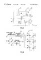
- FIG. 1is an overview of a system utilizing a variable speed induction motor according to the present invention.
- FIG. 2is an alternate embodiment showing a 2-stage environmental demand apparatus.
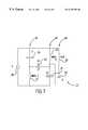
- FIG. 3is a schematic illustration of the stator windings and triac placement thereon.
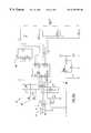
- FIG. 4is a schematic of the motor controller according to a preferred embodiment of the invention.
- FIG. 5is a flow chart detailing the series/parallel switching and firing delay adjustment operation of the controller.
- FIG. 6is a schematic of an alternative motor controller showing triac control of the auxiliary winding.
- FIG. 7is a schematic showing alternative winding arrangements.
- an operational system 11such as an HVAC system, has speed demand system 13 derived from environmental sensing and control units such as a thermostat or other furnace control apparatus; a motor controller 15 for accepting input from the environmental demand system 13 and outputting control signals to a motor 17 which drives a load 19 , such as a blower unit, fan blades or other compressible fluid moving mechanisms as represented in FIG. 1 by a fan blade 20 .
- a tachometer 21such as a Hall effect device or other known angular speed measuring means is placed to measure motor speed and report the speed information back to the motor controller 15 .
- the speed demand system 13is illustrated as having a temperature probe 23 in an air plenum 25 for its sensing unit upon which the speed demand for the motor 17 would be determined and communicated to the motor controller 15 .
- Various known demand systems and operationsmay be used in the system of the present invention.
- an external environmental control unitsuch as a thermostat 27 may only give the motor controller an on/off signal at which point an internal or separately placed, speed demand system 29 , such as one having differential temperature sensors 26 , 28 located within the plenum 25 , may determine the speed requirements for the motor 17 and report them to the motor controller 15 .
- first and second main windings 31 , 33 , respectively, and auxiliary winding 35 of the motor 17are shown connected across a voltage supply 36 as parallel legs 45 , 47 , 49 respectively of the stator circuit 37 of the motor.
- the windings 31 , 33 , 35need not have an equal number of turns, as illustrated in FIG. 7 . Any or all of the main and auxiliary windings may have an unequal number of turns selected to provide the greatest motor efficiency when operating the motor at a given speed and in a given mode.
- First and second main windings 31 , 33have first and second triac 39 , 41 , respectively, at opposing ends of their parallel legs.
- a third triac 43provides a switchable path between the main winding parallel legs 45 , 47 to provide in-series operation of the main windings by operating the third triac 43 while the first and second triacs 39 , 41 are not operational.
- the auxiliary winding leg 49is shown with a constant capacitor 51 , it is envisioned that any known arrangement of start and run capacitors may be utilized with the present invention.
- the auxiliary winding 49is preferably left in parallel with the main windings to provide a constant sinusoidal component to the total power in the windings.
- the motor controller 15comprises a microprocessor or programmable microcontroller 53 with an internal oscillator, accepting a speed demand 55 input from the environmental demand unit 13 and a tachometer input 57 from the tachometer 21 ; a rectifying diode 56 , a filter capacitor 58 , a voltage regulator 59 across AC line power 61 , a resistor 63 for establishing zero voltage detection to the microcontroller 53 , and first, second, and third opto-isolators 65 , 67 , 69 for control inputs to the respective first, second and third triacs 39 , 41 , 43 .
- the microprocessor 53is preferably a low power device such as model No. PIC 12C508, available from Microchip Technology Inc., of Phoenix, Ariz., which draws on the order of 1-2 mA.
- the voltage regulator 59is also a lower power device preferably drawing less than 1 MA such as part no. VB408 from ST Microelectronics (www.st.com), and the opto-isolation units 65 , 67 , 69 such as part No. MOC 3023 from QT Optoelectronics Co. of Sunnyvale, Calif., are also low power devices operating at 5 mA.
- load current of the controlleris low and the IR drop required is low resulting in little wasted power or heat thereby allowing the present invention to generate low voltage by regulating the rectified AC power line 61 and thus saving the cost of a transformer.
- a resistor divider from the power linemay be used to lower the voltage, with about one watt of additional power loss, so that a low voltage regulator may be used.
- the LEDs of the opto-isolators, or optically coupled trigger devices 65 , 67 , 69are driven by a first and second output lines 71 , 73 from the microcontroller 53 .
- the serial winding operation triac trigger device 69is connected in opposite polarity to the parallel winding operation trigger devices 65 and 67 .
- the parallel trigger devices 65 , 67are exclusively OR'ed with the serial trigger device 69 . If both microprocessor outputs 71 , 73 are equal all triacs 39 , 41 , 43 are off. If the first output 71 is high, the parallel winding operation triacs 39 , 41 will conduct. If the second output 73 is high, the serial winding operation triac 43 will conduct.
- a motor controller 75is easily connectable to a conventional furnace as is manufactured in volume today.
- a furnace controller, or environmental demand systemhas two 120VAC inputs to the motor controller. If the first input 77 is high, i.e. 120VAC present, this corresponds to the furnace being in the air conditioning mode. In the air conditioning mode the demand is for the fan to be at or near, i.e. substantially, the maximum motor speed. If the second input 79 is high, this corresponds to the furnace being in the heating mode, and asking the fan to be at a preset speed within the range of about sixty to ninety percent of maximum speed. There is a third input 81 coming from a thermostat having a fan switch.
- the motor controllermay have a EEPROM 83 with a preset variety of motor speeds for selection of the proper speed setting for each of the above discussed modes of the furnace.
- the furnaceis placed in one of the three operating modes, and the installer then presses an up button 85 or down button 87 to increase or decrease the motor speed.
- that speed settingis locked in, or set, for that operational mode.
- the settingis kept in EEPROM for the controller to use indefinitely. Then the furnace is changed to the next mode and the process is repeated until all three modes are set.
- the motoris variable over a wide range of speeds but has only two or three widely spaced motor speed settings.
- a fourth triac 89is placed in series with the auxiliary winding and is turned off when all three of the main winding triacs 39 , 41 , 43 are off.
- a switch point for determining series and parallel winding operationsis empirically selected for the motor system between two numbers on the speed setting scale.
- the switch pointmay e.g. be between twelve and thirteen with twelve or less being series windings operation and thirteen or greater being parallel windings operation.
- the switch in motor operationneed not occur at fifty percent of motor speed and can be different for different constructions and arrangements of motors. For example, it has been found that high speed series operation of the windings is more efficient than low speed parallel operation of the windings. Therefore when in that range of speed settings, the operator may wish to push the series windings operation settings to a higher percentage of the rated motor speed before changing operation to parallel windings, perhaps to as much as seventy plus percent of rated speed.
- hysteresisWhen the motor is operating near the switchpoint, hysteresis should be provided in order to minimize the number of changes in operation mode between series and parallel.
- software supplied hysteresisserves to prevent chatter at operational points close to the switch over point. Opto-isolation prevents back EMF from stressing the controller or the triacs.
- delays in switchingmay be programmed, e.g. power may be turned off for one or more half cycles between series/parallel transitions to prevent any possible shorting of the triacs 39 , 41 , 43 across the line.
- the speed demand input 55is sent to the microprocessor 53 .
- the speed demand input 55may, for example, be a pulse width modulated (PWM) signal although other forms of input may be accommodated.
- PWMpulse width modulated
- the microprocessor 53counts the PWM high cycle, i.e. decodes or translates, the speed demand input to a speed setting number level usable by the microprocessor and compares it to the current speed setting.
- the number of speed settingsis limited only by the microprocessor capability, but in the present embodiment is preferably between two and one thousand twenty four choices, inclusive, which is believed to be adequate for most variable speed applications.
- the PWM countis divided by four to limit the number of speed setting number level choices.
- the speed setting levelis greater than the current speed setting, the speed setting is incremented. If the speed setting level is less than the current speed setting, the speed setting is decremented. When a new speed setting is established, it serves as index number for a look-up table returning the triac to be operated and the appropriate phase delay timing for that speed. Separate tables may be used for series operation and parallel operation. Alternatively, the phase delay may be calculated according to an equation such as for a speed to load curve or speed to firing delay curve contained within the microprocessor.
Landscapes
- Engineering & Computer Science (AREA)
- Power Engineering (AREA)
- Control Of Ac Motors In General (AREA)
Abstract
Description
Claims (24)
Priority Applications (6)
| Application Number | Priority Date | Filing Date | Title |
|---|---|---|---|
| US09/475,687US6329783B1 (en) | 1999-12-30 | 1999-12-30 | Apparatus for continuously variable speed electric motor applications |
| CA002395956ACA2395956A1 (en) | 1999-12-30 | 2000-12-21 | Apparatus for continuously variable speed electric motor applications |
| AU22906/01AAU2290601A (en) | 1999-12-30 | 2000-12-21 | Apparatus for continuously variable speed electric motor applications |
| EP00986717AEP1264393A1 (en) | 1999-12-30 | 2000-12-21 | Apparatus for continuously variable speed electric motor applications |
| PCT/US2000/035118WO2001050589A1 (en) | 1999-12-30 | 2000-12-21 | Apparatus for continuously variable speed electric motor applications |
| JP2001550860AJP2004523189A (en) | 1999-12-30 | 2000-12-21 | Continuous variable speed motor application equipment |
Applications Claiming Priority (1)
| Application Number | Priority Date | Filing Date | Title |
|---|---|---|---|
| US09/475,687US6329783B1 (en) | 1999-12-30 | 1999-12-30 | Apparatus for continuously variable speed electric motor applications |
Publications (1)
| Publication Number | Publication Date |
|---|---|
| US6329783B1true US6329783B1 (en) | 2001-12-11 |
Family
ID=23888676
Family Applications (1)
| Application Number | Title | Priority Date | Filing Date |
|---|---|---|---|
| US09/475,687Expired - LifetimeUS6329783B1 (en) | 1999-12-30 | 1999-12-30 | Apparatus for continuously variable speed electric motor applications |
Country Status (6)
| Country | Link |
|---|---|
| US (1) | US6329783B1 (en) |
| EP (1) | EP1264393A1 (en) |
| JP (1) | JP2004523189A (en) |
| AU (1) | AU2290601A (en) |
| CA (1) | CA2395956A1 (en) |
| WO (1) | WO2001050589A1 (en) |
Cited By (32)
| Publication number | Priority date | Publication date | Assignee | Title |
|---|---|---|---|---|
| US20020180403A1 (en)* | 2001-05-24 | 2002-12-05 | Brown Fred A. | Efficient stator |
| WO2003023284A1 (en) | 2001-09-10 | 2003-03-20 | Varidigm Corporation | Variable output heating and cooling control |
| US20030091441A1 (en)* | 2001-11-14 | 2003-05-15 | Wen-Shi Huang | Fan control system using a microcontroller |
| US20040169479A1 (en)* | 2003-02-28 | 2004-09-02 | A. O. Smith Corporation | Multiple-speed electric machine and method of operating the same |
| US20040189242A1 (en)* | 2003-03-26 | 2004-09-30 | Wavecrest Laboratories, Llc | Multiphase motor having different winding configurations for respective speed ranges |
| US20040247449A1 (en)* | 2002-07-12 | 2004-12-09 | Wen-Chuan Ma | Fan control system using a microcontroller |
| US20040251344A1 (en)* | 2003-02-07 | 2004-12-16 | Varidigm Corporation | Pressure sensing system |
| US6864659B2 (en) | 2001-07-12 | 2005-03-08 | Varidigm Corporation | Variable speed controller for air moving applications using an AC induction motor |
| US20050082277A1 (en)* | 2003-09-17 | 2005-04-21 | Gordon Jones | System and method for controlling heating and ventilating systems |
| US20050135794A1 (en)* | 2003-12-22 | 2005-06-23 | General Electric Company | Method and system for negative torque reduction in a brushless DC motor |
| US20050162108A1 (en)* | 2003-09-12 | 2005-07-28 | A. O. Smith Corporation | Electric machine and method of operating the electric machine |
| EP1603223A1 (en)* | 2004-05-28 | 2005-12-07 | Lg Electronics Inc. | Variable speed motor |
| US20060033458A1 (en)* | 2003-01-21 | 2006-02-16 | Grundfos A/S | Method for controlling the firing angle of an electric motor |
| US20060103340A1 (en)* | 2004-11-17 | 2006-05-18 | Samsung Electronics Co., Ltd. | Single-phase induction motor and method for reducing noise in the same |
| US7075255B1 (en)* | 2005-07-26 | 2006-07-11 | Varidigm Corporation | Variable speed controller for a family of multi-tap motors |
| US20060273751A1 (en)* | 2005-06-06 | 2006-12-07 | Lutron Electronics Co., Ltd. | Method and apparatus for quiet variable motor speed control |
| US20070024220A1 (en)* | 2003-10-24 | 2007-02-01 | Shirazee Nabeel A | Magnetic gearing of permanent magnet brushless motors |
| US20070069683A1 (en)* | 2003-09-12 | 2007-03-29 | A. O. Smith Corporation | Electric machine and method of operating the electric machine |
| US20070099138A1 (en)* | 2005-10-17 | 2007-05-03 | Thomas & Betts International, Inc. | System and method for improving the thermal efficiency of a heating system |
| US7489094B2 (en) | 2005-11-18 | 2009-02-10 | Lutron Electronics Co., Inc. | Method and apparatus for quiet fan speed control |
| WO2010120744A2 (en) | 2009-04-14 | 2010-10-21 | Warsaw Orthopedic, Inc. | Minimally invasive instrument and method to treat periodontal disease |
| US20110129368A1 (en)* | 2009-11-30 | 2011-06-02 | Franklin Electric Company, Inc. | Variable speed drive system |
| US20110181226A1 (en)* | 2010-01-22 | 2011-07-28 | Steiner Robert E | Systems and method for motor speed control |
| US20110204832A1 (en)* | 2010-02-19 | 2011-08-25 | Rbc Manufacturing Corporation | Systems and methods for controlling operations of a motor |
| US8664903B2 (en) | 2011-06-27 | 2014-03-04 | Franklin Electric Company, Inc. | Adaptive flux control drive |
| US20140247038A1 (en)* | 2013-03-01 | 2014-09-04 | Hon Hai Precision Industry Co., Ltd. | Fan speed testing device |
| US20140368093A1 (en)* | 2013-06-12 | 2014-12-18 | V Square/R Llc | Multiple Field Motor Controller |
| US11313558B2 (en) | 2015-03-30 | 2022-04-26 | Maxitrol Company | Constant efficiency controller |
| US11708005B2 (en) | 2021-05-04 | 2023-07-25 | Exro Technologies Inc. | Systems and methods for individual control of a plurality of battery cells |
| US11722026B2 (en) | 2019-04-23 | 2023-08-08 | Dpm Technologies Inc. | Fault tolerant rotating electric machine |
| US11967913B2 (en) | 2021-05-13 | 2024-04-23 | Exro Technologies Inc. | Method and apparatus to drive coils of a multiphase electric machine |
| US12176836B2 (en) | 2018-09-05 | 2024-12-24 | Dpm Technologies Inc. | Systems and methods for intelligent energy storage and provisioning using an energy storage control system |
Families Citing this family (4)
| Publication number | Priority date | Publication date | Assignee | Title |
|---|---|---|---|---|
| US7847510B2 (en)* | 2008-02-29 | 2010-12-07 | Johnson Controls Technology Company | Controlling switching of thyristors to reduce power loss in variable speed motor |
| EP2104221A1 (en)* | 2008-03-22 | 2009-09-23 | Grundfos Management A/S | Method for controlling a multi-phase electromotor operated in a star circuit |
| US11611302B2 (en)* | 2020-09-26 | 2023-03-21 | Emerson Electric Co. | Systems and methods for controlling inducer motor speed |
| US12278580B2 (en) | 2020-09-26 | 2025-04-15 | Copeland Comfort Control Lp | Systems and methods for controlling inducer motor speed |
Citations (12)
| Publication number | Priority date | Publication date | Assignee | Title |
|---|---|---|---|---|
| US3582737A (en)* | 1969-10-07 | 1971-06-01 | Gen Electric | Speed control of a wye-connected induction motor utilizing delta connected triggerable biconductive devices |
| US4443749A (en)* | 1982-10-07 | 1984-04-17 | A. O. Smith Corporation | Multiple speed split-phase induction motor |
| US4467257A (en)* | 1982-10-07 | 1984-08-21 | A. O. Smith Corporation | Multiple speed induction motor |
| US4477760A (en)* | 1983-03-24 | 1984-10-16 | Westinghouse Electric Corp. | Continuous pole amplitude modulated electric machines |
| DE3607162A1 (en)* | 1986-03-05 | 1987-09-10 | Grundfos As | AC motor especially for circulation pumps |
| US4779034A (en) | 1986-08-07 | 1988-10-18 | Shepard Jr Francis H | Forced commutation for variable speed motor |
| DE4222431A1 (en)* | 1992-07-09 | 1994-01-13 | Wilo Gmbh | Device for switching between windings of a single-phase electric motor - has Triacs across each auxiliary winding in chain parallel to main winding, with control unit for gates |
| US5614799A (en)* | 1994-07-14 | 1997-03-25 | Mts Systems Corporation | Brushless direct current motor having adjustable motor characteristics |
| US5650707A (en)* | 1995-09-28 | 1997-07-22 | Electric Power Research Institute, Inc. | Inverter-controlled induction machine with an extended speed range |
| US5675230A (en)* | 1994-03-01 | 1997-10-07 | Seagate Technology, Inc. | Method and apparatus for dynamic low voltage spindle motor operation |
| US5680021A (en) | 1993-02-22 | 1997-10-21 | General Electric Company | Systems and methods for controlling a draft inducer for a furnace |
| US5867005A (en) | 1997-12-18 | 1999-02-02 | Comair Rotron, Inc. | AC motor winding circuit |
- 1999
- 1999-12-30USUS09/475,687patent/US6329783B1/ennot_activeExpired - Lifetime
- 2000
- 2000-12-21CACA002395956Apatent/CA2395956A1/ennot_activeAbandoned
- 2000-12-21JPJP2001550860Apatent/JP2004523189A/enactivePending
- 2000-12-21AUAU22906/01Apatent/AU2290601A/ennot_activeAbandoned
- 2000-12-21WOPCT/US2000/035118patent/WO2001050589A1/ennot_activeApplication Discontinuation
- 2000-12-21EPEP00986717Apatent/EP1264393A1/ennot_activeWithdrawn
Patent Citations (12)
| Publication number | Priority date | Publication date | Assignee | Title |
|---|---|---|---|---|
| US3582737A (en)* | 1969-10-07 | 1971-06-01 | Gen Electric | Speed control of a wye-connected induction motor utilizing delta connected triggerable biconductive devices |
| US4443749A (en)* | 1982-10-07 | 1984-04-17 | A. O. Smith Corporation | Multiple speed split-phase induction motor |
| US4467257A (en)* | 1982-10-07 | 1984-08-21 | A. O. Smith Corporation | Multiple speed induction motor |
| US4477760A (en)* | 1983-03-24 | 1984-10-16 | Westinghouse Electric Corp. | Continuous pole amplitude modulated electric machines |
| DE3607162A1 (en)* | 1986-03-05 | 1987-09-10 | Grundfos As | AC motor especially for circulation pumps |
| US4779034A (en) | 1986-08-07 | 1988-10-18 | Shepard Jr Francis H | Forced commutation for variable speed motor |
| DE4222431A1 (en)* | 1992-07-09 | 1994-01-13 | Wilo Gmbh | Device for switching between windings of a single-phase electric motor - has Triacs across each auxiliary winding in chain parallel to main winding, with control unit for gates |
| US5680021A (en) | 1993-02-22 | 1997-10-21 | General Electric Company | Systems and methods for controlling a draft inducer for a furnace |
| US5675230A (en)* | 1994-03-01 | 1997-10-07 | Seagate Technology, Inc. | Method and apparatus for dynamic low voltage spindle motor operation |
| US5614799A (en)* | 1994-07-14 | 1997-03-25 | Mts Systems Corporation | Brushless direct current motor having adjustable motor characteristics |
| US5650707A (en)* | 1995-09-28 | 1997-07-22 | Electric Power Research Institute, Inc. | Inverter-controlled induction machine with an extended speed range |
| US5867005A (en) | 1997-12-18 | 1999-02-02 | Comair Rotron, Inc. | AC motor winding circuit |
Non-Patent Citations (2)
| Title |
|---|
| Joseph D. Law and Thomas A. Lipo: A Single Phase Induction Motor Voltage Controller with improved Performance, IEEE Transactions on Power Electronics, vol. PE-1, No. 4, 240-247, Oct. 1986. |
| M.M. Marcos et al.: A Solid-State Speed Controller for Capacitor Motors Driving Ventilation Fans, IEEE Transactions on Industry Applications, vol. 30, No. 3, 656-663, May 1994. |
Cited By (57)
| Publication number | Priority date | Publication date | Assignee | Title |
|---|---|---|---|---|
| US6741061B2 (en)* | 2001-05-24 | 2004-05-25 | Comair Rotron, Inc. | Efficient stator |
| US20020180403A1 (en)* | 2001-05-24 | 2002-12-05 | Brown Fred A. | Efficient stator |
| US6864659B2 (en) | 2001-07-12 | 2005-03-08 | Varidigm Corporation | Variable speed controller for air moving applications using an AC induction motor |
| WO2003023284A1 (en) | 2001-09-10 | 2003-03-20 | Varidigm Corporation | Variable output heating and cooling control |
| US20050159844A1 (en)* | 2001-09-10 | 2005-07-21 | Sigafus Paul E. | Variable output heating and cooling control |
| US7293718B2 (en) | 2001-09-10 | 2007-11-13 | Varidigm Corporation | Variable output heating and cooling control |
| US6866202B2 (en) | 2001-09-10 | 2005-03-15 | Varidigm Corporation | Variable output heating and cooling control |
| US20030091441A1 (en)* | 2001-11-14 | 2003-05-15 | Wen-Shi Huang | Fan control system using a microcontroller |
| US6779981B2 (en)* | 2001-11-14 | 2004-08-24 | Delta Electronics, Inc. | Fan control system using a microcontroller |
| US20040247449A1 (en)* | 2002-07-12 | 2004-12-09 | Wen-Chuan Ma | Fan control system using a microcontroller |
| US8905721B2 (en)* | 2002-07-12 | 2014-12-09 | Delta Electronics Inc. | Fan control system using a microcontroller |
| US7859211B2 (en) | 2003-01-21 | 2010-12-28 | Grundfos A/S | Method for controlling the firing angle of an electric motor |
| US20070114957A1 (en)* | 2003-01-21 | 2007-05-24 | Grundfos A/S | Method for controlling the firing angle of an electric motor |
| US7166974B2 (en)* | 2003-01-21 | 2007-01-23 | Grundfos A/S | Method for controlling the firing angle of an electric motor |
| US20060033458A1 (en)* | 2003-01-21 | 2006-02-16 | Grundfos A/S | Method for controlling the firing angle of an electric motor |
| US20040251344A1 (en)* | 2003-02-07 | 2004-12-16 | Varidigm Corporation | Pressure sensing system |
| US20040169479A1 (en)* | 2003-02-28 | 2004-09-02 | A. O. Smith Corporation | Multiple-speed electric machine and method of operating the same |
| US7045979B2 (en)* | 2003-02-28 | 2006-05-16 | A.O. Smith Corporation | Multiple-speed electric machine and method of operating the same |
| US20040189242A1 (en)* | 2003-03-26 | 2004-09-30 | Wavecrest Laboratories, Llc | Multiphase motor having different winding configurations for respective speed ranges |
| US6853107B2 (en)* | 2003-03-26 | 2005-02-08 | Wavecrest Laboratories, Llc | Multiphase motor having different winding configurations for respective speed ranges |
| US20050162108A1 (en)* | 2003-09-12 | 2005-07-28 | A. O. Smith Corporation | Electric machine and method of operating the electric machine |
| US20070069683A1 (en)* | 2003-09-12 | 2007-03-29 | A. O. Smith Corporation | Electric machine and method of operating the electric machine |
| US7327118B2 (en) | 2003-09-12 | 2008-02-05 | A. O. Smith Corporation | Electric machine and method of operating the electric machine |
| US7268505B2 (en)* | 2003-09-12 | 2007-09-11 | A. O. Smith Corporation | Electric machine and method of operating the electric machine |
| US7177534B2 (en) | 2003-09-17 | 2007-02-13 | Air System Components, L.P. | System and method for controlling heating and ventilating systems |
| US20050082277A1 (en)* | 2003-09-17 | 2005-04-21 | Gordon Jones | System and method for controlling heating and ventilating systems |
| US7382103B2 (en)* | 2003-10-24 | 2008-06-03 | Electronica Products Limited | Magnetic gearing of permanent magnet brushless motors |
| US20070024220A1 (en)* | 2003-10-24 | 2007-02-01 | Shirazee Nabeel A | Magnetic gearing of permanent magnet brushless motors |
| US20050135794A1 (en)* | 2003-12-22 | 2005-06-23 | General Electric Company | Method and system for negative torque reduction in a brushless DC motor |
| US7091691B2 (en) | 2004-05-28 | 2006-08-15 | Lg Electronics Inc. | Variable speed motor |
| EP1603223A1 (en)* | 2004-05-28 | 2005-12-07 | Lg Electronics Inc. | Variable speed motor |
| US7245105B2 (en)* | 2004-11-17 | 2007-07-17 | Samsung Electronics Co., Ltd. | Single-phase induction motor and method for reducing noise in the same |
| US20060103340A1 (en)* | 2004-11-17 | 2006-05-18 | Samsung Electronics Co., Ltd. | Single-phase induction motor and method for reducing noise in the same |
| US7330004B2 (en) | 2005-06-06 | 2008-02-12 | Lutron Electronics Co., Inc. | Method and apparatus for quiet variable motor speed control |
| US20060273751A1 (en)* | 2005-06-06 | 2006-12-07 | Lutron Electronics Co., Ltd. | Method and apparatus for quiet variable motor speed control |
| US7075255B1 (en)* | 2005-07-26 | 2006-07-11 | Varidigm Corporation | Variable speed controller for a family of multi-tap motors |
| US20070099138A1 (en)* | 2005-10-17 | 2007-05-03 | Thomas & Betts International, Inc. | System and method for improving the thermal efficiency of a heating system |
| US7744366B2 (en)* | 2005-10-17 | 2010-06-29 | Thomas & Betts International, Inc. | System and method for improving the thermal efficiency of a heating system |
| US7489094B2 (en) | 2005-11-18 | 2009-02-10 | Lutron Electronics Co., Inc. | Method and apparatus for quiet fan speed control |
| US20100109597A1 (en)* | 2005-11-18 | 2010-05-06 | Lutron Electronics Co., Inc. | Method and apparatus for quiet fan speed control |
| US8193744B2 (en) | 2005-11-18 | 2012-06-05 | Lutron Electronics Co., Inc. | Method and apparatus for quiet fan speed control |
| WO2010120744A2 (en) | 2009-04-14 | 2010-10-21 | Warsaw Orthopedic, Inc. | Minimally invasive instrument and method to treat periodontal disease |
| US20110129368A1 (en)* | 2009-11-30 | 2011-06-02 | Franklin Electric Company, Inc. | Variable speed drive system |
| US8760089B2 (en) | 2009-11-30 | 2014-06-24 | Franklin Electric Company, Inc. | Variable speed drive system |
| US8373378B2 (en)* | 2010-01-22 | 2013-02-12 | Robert E. Steiner | Systems and method for motor speed control |
| US20110181226A1 (en)* | 2010-01-22 | 2011-07-28 | Steiner Robert E | Systems and method for motor speed control |
| US8378618B2 (en)* | 2010-02-19 | 2013-02-19 | Sntech, Inc. | Systems and methods for controlling operations of a motor |
| US20110204832A1 (en)* | 2010-02-19 | 2011-08-25 | Rbc Manufacturing Corporation | Systems and methods for controlling operations of a motor |
| US8664903B2 (en) | 2011-06-27 | 2014-03-04 | Franklin Electric Company, Inc. | Adaptive flux control drive |
| US20140247038A1 (en)* | 2013-03-01 | 2014-09-04 | Hon Hai Precision Industry Co., Ltd. | Fan speed testing device |
| US20140368093A1 (en)* | 2013-06-12 | 2014-12-18 | V Square/R Llc | Multiple Field Motor Controller |
| US9397603B2 (en)* | 2013-06-12 | 2016-07-19 | V Square/R Llc | Multiple field motor controller |
| US11313558B2 (en) | 2015-03-30 | 2022-04-26 | Maxitrol Company | Constant efficiency controller |
| US12176836B2 (en) | 2018-09-05 | 2024-12-24 | Dpm Technologies Inc. | Systems and methods for intelligent energy storage and provisioning using an energy storage control system |
| US11722026B2 (en) | 2019-04-23 | 2023-08-08 | Dpm Technologies Inc. | Fault tolerant rotating electric machine |
| US11708005B2 (en) | 2021-05-04 | 2023-07-25 | Exro Technologies Inc. | Systems and methods for individual control of a plurality of battery cells |
| US11967913B2 (en) | 2021-05-13 | 2024-04-23 | Exro Technologies Inc. | Method and apparatus to drive coils of a multiphase electric machine |
Also Published As
| Publication number | Publication date |
|---|---|
| JP2004523189A (en) | 2004-07-29 |
| CA2395956A1 (en) | 2001-07-12 |
| EP1264393A1 (en) | 2002-12-11 |
| AU2290601A (en) | 2001-07-16 |
| WO2001050589A1 (en) | 2001-07-12 |
Similar Documents
| Publication | Publication Date | Title |
|---|---|---|
| US6329783B1 (en) | Apparatus for continuously variable speed electric motor applications | |
| EP0856936B1 (en) | Motor controller | |
| US6801013B2 (en) | PSC motor system for use in HVAC applications | |
| WO2003007468A9 (en) | Variable speed controller for air moving applications using an acinduction motor | |
| US3499297A (en) | Variable capacity refrigeration system | |
| US6952088B2 (en) | PSC motor system for use in HVAC applications with improved start-up | |
| US7272302B2 (en) | PSC motor system for use in HVAC applications with field adjustment and fail-safe capabilities | |
| US5448141A (en) | Adjustable speed drive for residential applications | |
| US6603280B2 (en) | Motor controller | |
| KR100946719B1 (en) | Multi-programmable constant flow control device of variable speed non-commutator motor | |
| US6570778B2 (en) | Adjustable speed drive for single-phase induction motors | |
| AU681766B2 (en) | Airflow control for variable speed blowers | |
| CA2955447C (en) | Rotation speed control system and method for an ec motor | |
| US10852044B1 (en) | Simple low-cost retrofit device and method to replace a variable air flow electronically commutated motor with a permanent split capacitor motor capable of operating at multiple speed settings | |
| US6456023B1 (en) | Method and apparatus to control a variable speed motor | |
| US6097171A (en) | Method and apparatus for controlling an induction motor | |
| EP0401818A1 (en) | A current controller and method for a DC motor | |
| EP3471261B1 (en) | Control system and control method | |
| CN110431359B (en) | Temperature regulation system and power regulation device | |
| AU2013404555B2 (en) | Control apparatus for DC variable frequency motor | |
| US7075255B1 (en) | Variable speed controller for a family of multi-tap motors | |
| WO2018082103A1 (en) | A thermostat apparatus and a temperature regulation system | |
| JPH09149690A (en) | Inverter air conditioner | |
| KR200380870Y1 (en) | Fan driving circuit for positive pressure-to-output characteristic | |
| JPH06101893A (en) | Air conditioner control method |
Legal Events
| Date | Code | Title | Description |
|---|---|---|---|
| AS | Assignment | Owner name:GAS RESEARCH INSTITUTE, ILLINOIS Free format text:ASSIGNMENT OF ASSIGNORS INTEREST;ASSIGNORS:VRIONIS, NICKOLAS G.;EICHORN, RONALD L.;REEL/FRAME:010798/0380;SIGNING DATES FROM 20000412 TO 20000413 | |
| STCF | Information on status: patent grant | Free format text:PATENTED CASE | |
| AS | Assignment | Owner name:VARIDIGM CORPORATION, MINNESOTA Free format text:ASSIGNMENT OF ASSIGNORS INTEREST;ASSIGNOR:GAS RESEARCH INSTITUTE;REEL/FRAME:013231/0921 Effective date:20020301 | |
| FPAY | Fee payment | Year of fee payment:4 | |
| FPAY | Fee payment | Year of fee payment:8 | |
| AS | Assignment | Owner name:ACACIA RESEARCH GROUP LLC, TEXAS Free format text:ASSIGNMENT OF ASSIGNORS INTEREST;ASSIGNOR:VARIDIGM CORPORATION;REEL/FRAME:029013/0427 Effective date:20120831 Owner name:HVAC MODULATION TECHNOLOGIES LLC, TEXAS Free format text:ASSIGNMENT OF ASSIGNORS INTEREST;ASSIGNOR:ACACIA RESEARCH GROUP LLC;REEL/FRAME:029013/0580 Effective date:20120918 | |
| FEPP | Fee payment procedure | Free format text:PAT HOLDER NO LONGER CLAIMS SMALL ENTITY STATUS, ENTITY STATUS SET TO UNDISCOUNTED (ORIGINAL EVENT CODE: STOL); ENTITY STATUS OF PATENT OWNER: LARGE ENTITY | |
| FPAY | Fee payment | Year of fee payment:12 |