US6328930B1 - Apparatus for performing diagnostic testing - Google Patents
Apparatus for performing diagnostic testingDownload PDFInfo
- Publication number
- US6328930B1 US6328930B1US09/501,219US50121900AUS6328930B1US 6328930 B1US6328930 B1US 6328930B1US 50121900 AUS50121900 AUS 50121900AUS 6328930 B1US6328930 B1US 6328930B1
- Authority
- US
- United States
- Prior art keywords
- assembly
- luminescent
- film
- testing
- condition
- Prior art date
- Legal status (The legal status is an assumption and is not a legal conclusion. Google has not performed a legal analysis and makes no representation as to the accuracy of the status listed.)
- Expired - Fee Related
Links
Images


Classifications
- G—PHYSICS
- G01—MEASURING; TESTING
- G01N—INVESTIGATING OR ANALYSING MATERIALS BY DETERMINING THEIR CHEMICAL OR PHYSICAL PROPERTIES
- G01N21/00—Investigating or analysing materials by the use of optical means, i.e. using sub-millimetre waves, infrared, visible or ultraviolet light
- G01N21/75—Systems in which material is subjected to a chemical reaction, the progress or the result of the reaction being investigated
- G01N21/76—Chemiluminescence; Bioluminescence
- G—PHYSICS
- G01—MEASURING; TESTING
- G01N—INVESTIGATING OR ANALYSING MATERIALS BY DETERMINING THEIR CHEMICAL OR PHYSICAL PROPERTIES
- G01N21/00—Investigating or analysing materials by the use of optical means, i.e. using sub-millimetre waves, infrared, visible or ultraviolet light
- G01N21/62—Systems in which the material investigated is excited whereby it emits light or causes a change in wavelength of the incident light
- G01N21/63—Systems in which the material investigated is excited whereby it emits light or causes a change in wavelength of the incident light optically excited
- G01N21/64—Fluorescence; Phosphorescence
- G01N21/645—Specially adapted constructive features of fluorimeters
- G—PHYSICS
- G01—MEASURING; TESTING
- G01N—INVESTIGATING OR ANALYSING MATERIALS BY DETERMINING THEIR CHEMICAL OR PHYSICAL PROPERTIES
- G01N2201/00—Features of devices classified in G01N21/00
- G01N2201/02—Mechanical
- G01N2201/022—Casings
- G01N2201/0221—Portable; cableless; compact; hand-held
Definitions
- the present inventionrelates to copending U.S. non-provisional patent application, Ser. No. 09/412,845 entitled “Diagnostic Assay System and Method”; filed concurrently herewith.
- the present inventionrelates generally to diagnostic assay systems and methods capable for multiple samples in a simple and reliable manner.
- Luminometersconduct and record luminescent reactions generated, for instance, by a biological test fluid sample that contains a reagent of interest, such as an analyte, and a reagent in an assay element. Examples of these approaches include single-sample luminometers fitted with photographic multipliers; single-sample luminometers fitted with solid-state detectors; multiple sample luminometers; automatic luminometers with imaging systems based on CCD cameras; and photographic camera type luminometers.
- one provisionis, preferably, made for a hand-held, portable diagnostic assay system.
- the systemis operable for conducting and recording luminescent reactions, that generate luminescent signals, such as chemiluminescent and fluorescent signals, that are recordable an image recording medium, such as a film assemblage of the self-developing type.
- luminescent signalssuch as chemiluminescent and fluorescent signals
- an image recording mediumsuch as a film assemblage of the self-developing type.
- a housing assemblydefining a light-tight enclosure carrying at least the film unit and an exposure opening that optically communicates the film unit and the luminescent read-out signal.
- a film processing unit in the housingis operable for processing exposed self-developing film units passing therethrough.
- a sample carrier means or assemblythat has one condition for receiving a luminescent testing assembly and a second condition for exposing the film.
- the sample carrier assemblycan carry, in a light-tight manner, at least one luminescent testing assembly that is capable of generating a luminescent read-out signal recordable on the image recording medium in response to the testing assembly being actuated.
- the generated signalexposes the film unit.
- Developing the resultant latent imageis initiated when the film unit is advanced from the housing after passing through the film processing unit.
- the sample carrierhas an opening for receiving a test container of the luminescent testing assembly.
- the test containercomprises a reservoir that stores a luminescent testing means; which in a preferred embodiment is in the form of a fluid that is sealed by means of a sealing device. A portion of the reservoir is transparent for allowing transmission of the generated read-out signal to the film through an open exposure opening.
- a sampling device of the luminescent testing assemblycan sample a surface to be tested and is inserted, in a light-tight manner, within the test container such that a portion thereof is immersed in the fluid. If the sampling device contains a reagent that reacts with a reagent in the assay fluid, the generated luminescent signal can expose the film through the open exposure opening and transparent portion.
- the test containerincludes opaque means therein which serves, when the container is held in the sample carrier, to block ambient light from reaching the exposure opening.
- a sample carrier assemblycarries a luminescent sample test assembly and a luminescent control test assembly.
- Fluid transfer meanssuch as light-tight capillary grooves, allow transfer of the control and test fluids from separate ports therefor to the respective test assemblies.
- a means and method for achieving a quantification of the luminescent signal generated and recorded on the filmis achieved by reason of an optical filter.
- the filtercan have alternating light attenuating zones, such as transparent and opaque zones that act to delineate different sized read-out signals.
- the different sized imagescorrelate to corresponding different test results. Because of the light attenuation, different sized luminescent images will be visible through correspondingly different sized attenuation zones; thereby providing a visual measurement of the test results.
- the quantificationcan be obtained by pre-exposing the film with a gradation of different sized images.
- the different sizescorrespond to different predetermined outputs of the luminescent signals.
- provision is for a film overlaycomprising a series of different sized images thereon with each overlay image corresponding to different test outputs. In use the test image that is captured during the actual test can be compared to images on the overlay for quantifying the test result.
- Methodsare contemplated for conducting and recording read-out signals that can expose the image recording material.
- FIG. 1is an exploded perspective schematic view illustrating several components forming one embodiment of a multiple sample diagnostic assay system of the present invention
- FIG. 1Ais an enlarged and fragmented schematic view of a film assemblage that can be used in connection with the invention
- FIG. 2is a schematic exploded perspective view illustrating components of the assay system
- FIG. 3is a bottom plan view of a sample carrier component of the assay system
- FIG. 4is a bottom plan view of alternate embodiment of a sample carrier
- FIG. 5is a view of an alternate embodiment of a diagnostic assay system of the present invention.
- FIG. 6is an enlarged schematic view of the interaction between the a sample carrier and a shutter mechanism
- FIG. 7is a plan view of an optical filtering arrangement for use in the diagnostic assay systems.
- FIG. 8is a plan view of another embodiment of a filtering arrangement
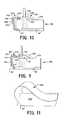
- FIGS. 9 and 10illustrate yet another preferred embodiment wherein an interlocking system is illustrated in first and second positions; respectively, and
- FIG. 11is a perspective view of a peelable dark slide.
- FIGS. 1-3for schematically illustrating one of the preferred embodiments of a multiple sample diagnostic assay system 10 .
- the diagnostic assay 10includes a light-tight, processor housing assembly 12 having the general configuration depicted and containing therewith a film box 14 . Contained in light-tight relationship to the film box 14 is a film assemblage 16 .
- the preferred embodiment of the film assemblageis similar to that described in copending and commonly assigned U.S. patent applications Ser. No. 08/738,772, now U.S. Pat. No. 5,838,999; and Ser. No. 08/829,914, now U.S. Pat. No. 5,848,316 a description thereof is incorporated herein as a part hereof.
- the film assemblage 16includes an elongated strip comprising a plurality of self-developing film units 20 secured end-to-end to connection strips in alternating arrangement to form a longitudinal strip. Weakened portions in the connection strips are structurally weakened to permit easy separation in a manner to be described.
- Each of the film unitsis, preferably, of the integral self-developing integral type.
- each of the film units 20includes a tab or leader portion 20 a , an image recording area 20 b , a pod 20 c of processing fluid located at a leading end portion, and a fluid trap 20 d at a trailing end.
- the photosensitive image recording area 20 bis positioned within the housing assembly so as to be exposed to a read-out signal of a luminescent activity.
- Luminescent activity or read-out as used in this specificationincludes any luminescent activity such as of the chemiluminescent type, fluorescence, infrared and other signals that are recordable on an image recording material.
- the pod 20 cis positioned adjacent the processing means, as will be described and a tab or leader portion 20 a of the leading film unit protrudes from a film exit 24 in the device so that the film unit may be manually grasped for pulling and processing of the film unit as will be described.
- the film exit 24is appropriately provided with flaps (not shown) or the like for providing a light-tight enclosure.
- the processor housing assembly 12includes a pair of generally rectangular and matable lower and upper plate-like processor housing portions 26 and 28 .
- the housing portionsare hingedly connected as at 29 to permit loading of the film box within a complementary shaped compartment within the processor.
- the housing assembly 12is,preferably, dimensioned to be hand-held and portable for providing a self-contained and portable diagnostic assay system that is convenient to use.
- the housing portions 26 and 28can be made of any material suitable to define, preferably, a light-tight enclosure 32 . While a hinged coupling is described, a wide variety of approaches for joining the two opposed housing components are envisioned.
- the lower processor housing portion 26is similar in construction to that described in the last-noted application and basically includes a film supporting wall (not shown) a processing fluid spreading structure 30 (not shown) for spreading the processing fluid ruptured from the pod in a well-known manner.
- a lower spread roller 34is rotatably supported in the lower housing portion for cooperating with a biased upper spread roller 36 in the upper housing portion 28 to define a pressure nip.
- the rollers 34 and 36serve to rupture the pod and spread the processing fluid as a film unit passes therethrough.
- the nipacts to inexpensively retain the film assemblage 16 within the housing prior to use of the device. Accordingly, the film can be transported and handled without fear of it becoming dislodged or otherwise separated.
- the upper housing 28includes a generally rectangular recess 40 that has pivotally mounted thereon, as at 42 , a shutter blade 44 .
- the shutter blade 44moves between light blocking and unblocking relationships relative to an exposure opening 48 that is in optical communication with an image portion of a film unit.
- a light-seal plate 50has a construction as shown to be mounted in and suitably secured to reside within the recess of the upper housing and includes an aperture 52 .
- the plate 50serves to rotatably mount, within the aperture 52 a rotatable test sample carrier 54 .
- the test sample carrier 54has a generally cylindrical configuration with a reduced diameter portion that has a snug, light-tight fit within the plate.
- the test sample carrier 54includes a passage 56 extending longitudinally therethrough.
- a plurality of linearly spaced apart stepped shoulders 58 a , 58 bare provided in the passageway for supporting a test sample device.
- a pair of arcuately spaced apart and downwardly protruding opening and closing pins 60 and 62 ; respectively, on the test sample carrieralternately engage the shutter to open and closed positions as the carrier is rotated in opposite directions; in a manner to be described.
- the sample carriercan be manually grasped about its periphery and turned in either direction.
- manual meanssuch as handles or motorized means can be used to rotate the sample carrier.
- the device 10is adapted for particular use in connection with a luminescent assay testing assembly 63 that includes an ampoule 64 and a test sample pick-up device 66 that is housed and cooperates with the ampoule in a manner to be described. It will be understood, however, that the test system to be described is but one of several which can be used in conjunction with the device.
- the luminescent testing assay assembly including the ampoule, fluid, and pick-up deviceare similar to that commercially available from Biotrace, Inc., Plainsboro, N.J. It will be understood that the device of the present invention can be used in connection with other similar diagnostic systems.
- the ampoule 64includes a generally hollow tubular housing for slidably receiving the pick-up device 66 .
- the housingis made of transparent plastic, and has an open end portion 68 that is adapted to receive the sample pick-up, and a closed end portion 70 .
- the present embodiment of the ampouleincludes a transparent housing, it will be appreciated that need not be the case. In the latter regard, however, the closed end portion should be transparent in order to transmit any luminescent activity; whereby the latter can form a latent image on the film.
- a sealing membrane 72is located generally transversely to the housing 67 so as to define a chamber or reservoir 74 with the closed end portion in order to sealingly accommodate an assay fluid 76 .
- the sealing membrane 72is made of a thin-walled metallic material that is impervious to fluid and ambient atmosphere.
- the sealing membraneis adapted to be punctured by the sample pick-up device 66 ; when the latter is inserted therethrough.
- the assay fluid 76can be one that generates a chemiluminescent signal in response to a reagent, such as ATP (Adenosine Triphosphate) being present on the sampling rings. ATP is used as an indicator of the presence of organic debris, such as microorganisms.
- the fluid 76can be, for example, a Firefly reagent which generates a light signal in response to ATP collected on the sampling device 66 .
- the sample pick-up deviceincludes a handle 78 , a stem 80 and a plurality of laterally extending sampling rings 82 .
- the sampling rings 82are used to engage a surface to be tested for micoroganisms.
- a usermerely rubs the rings against a surface to be tested, for instance, a food preparation surface and inserts the sampling ring into and through the membrane, whereupon the rings are immersed into the assay fluid.
- ATPis present, in significant amounts on the sampling rings, it will react with the reagent in the fluid and generate a luminescent read-out signal that is recordable on the film.
- the present inventioncontemplates use of a wide variety of fluids, membranes and sample pick-ups. The foregoing materials provide, but one of many that can be used in the context of the present invention.
- the luminescent testing assembly 63is provided with an opaque means in the form of a plastic collar 86 being formed in combination with a segmented the tubular housing 67 .
- the plastic collar 86has a central axially extending passageway 87 through which the sample pick-up 66 is inserted.
- An upper end portion 88is fit within a central passage of upper tubular portion 67 a and a lower end portion 90 is fit within a lower portion 67 b of the housing above the sealing membrane.
- a projecting rim 92extends radially from the collar and is adapted to rest on the shoulder 67 a.
- a usercan, for example, wipe the sampling rings on a surface to be tested for the presence of ATP.
- the ampoule housing 67is placed within the passage 56 with the shoulder 58 b being engaged by the collar rim 92 and the shoulder 58 a engaging a surface 67 c of the housing wherein the transparent closed end portion enters a reduced diameter portion of the passage 56 , whereby the ampoule is in an upstanding position with respect to the sample carrier.
- the sample carrierPrior to testing, the sample carrier. is in a non-exposing mode, whereby the passage 56 is circumferentially spaced from the aperture and the shutter blade is in the closed condition.
- the userinserts the test sample device 66 through the membrane so that the sampling rings are immersed within the assay fluid to initiate a chemiluminescent reaction, if the test ATP reacts with the reagent in the assay fluid; after a preselected time interval.
- the time intervalof course, varies as a function of several factors not relevant to the present invention. Timing such intervals is accomplished by means of a suitable timer 95 mounted on the device in any appropriate fashion and in exposing relationship (not shown) to the film unit.
- the timercan be started when the sampling rings are immersed into the assay fluid. Following the prescribed time period for generating luminescent reactions, as indicated by the timing device, the sample carrier is rotated to the film exposing position. During rotation, the opening pin engages the shutter and drives the latter to its unblocking condition, while the closing pin correspondingly disengages the shutter; whereby the film aperture is opened so that the film can be exposed.
- displacement stops(not shown) for controlling displacement of the sample carrier can be appropriately provided. Accordingly, the film can be exposed by luminescent activity, assuming one, of course, occurs. The time interval for such an exposure can vary upon several factors including the speed of the film.
- Actuation of the timer 100can occur manually or even automatically as, for example, in response to movement of the sample carrier by carrier drive means (not shown).
- carrier drive meansnot shown.
- the present inventionenvisions the use of film printable devices, such as LED's (not shown) that would be attached to the housing and otherwise actuatable to record desired information.
- the film tabis pulled, whereby the film unit emerges from the housing through the processing rollers.
- processing of the film unitsis initiated.
- the unit pulled from the deviceseparates and the next successive film unit is indexed to the exposure position for another test as a result of the pulling action on the strip.
- the testwill indicate either a positive or negative result in a manner that is quickly and easily ascertained.
- the resultis simple to read and understand and is one that does not require user interpretation, such as determining the color of a test result or calculating any quantification. It will be appreciated that as a consequence, a safe and simple diagnostic test is performed that provides a positive record of the test being conducted. Such testing is of particular benefit, particularly in the home testing market wherein it can be used for a variety of diagnostic tests with a certainty of results and a significant ease of operation.
- the sample carrier barrelneed not have the opening and closing pins acting in cooperation with a shutter and, in fact, does not cooperate with a shutter. Rather, the sample carrier barrel, in effect, acts as a shutter.
- a bottom surface of the barrelis covered by a light-blocking material 98 that has a low-coefficient of friction, such as felt.
- feltis disclosed in this embodiment, the present invention envisions a variety of materials that can be used in an equivalent manner. An opening in the felt is coincident with the passage 56 .
- the felt or other similar materialsprovide obviate the need for a shutter and shutter actuating mechanism.
- the present inventioncontemplates the use of a solenoid actuated shutter that would be operated by a suitable energizing means and provide somewhat greater control over the shuttering functions.
- FIGS. 4 and 5for illustrating another preferred embodiment of a multiple-sample processor 100 made according to the present invention. Structure of this embodiment similar to that of the previous embodiment will be indicated by like reference numerals with the addition of a prime mark.
- the sample processor 100includes a housing assembly 102 and a sample carrier assembly 104 that ate cooperable with each other in a manner to be described. Included in the housing are generally rectangular and matable lower and upper processor portions 106 and 108 which form a light-tight enclosure for housing a film assemblage 20 ′ like that described last-noted embodiment. Accordingly, a leading one of the film units is in a position for exposure within the housing and its tab 20 a protrudes.
- the housing portionsare hingedly connected as at 112 to permit loading of a film box 114 that is loadable within a complementary shaped compartment within the housing.
- the housing assembly 102is, preferably, dimensioned to be hand-held and portable for convenient use in the field.
- the housing portionsare made of any material suitable to define, preferably, a light-tight enclosure. While a hinged coupling is described, a wide variety of approaches for joining the two opposed housing components are envisioned.
- the lower processor housing portion 106is similar in construction to that described in the last-noted application. Basically, it includes a film supporting wall (not shown) a processing fluid spreading structure 30 ′ (not shown) for spreading the processing fluid ruptured from the pod in a well-known manner.
- a lower spread roller 34 ′is rotatably supported in the lower housing portion for cooperating with a biased upper spread roller 36 ′ in the upper housing portion 28 to define a pressure nip.
- the spread rollersserve to rupture the pod and spread the processing fluid.
- the nip thereofacts to inexpensively retain the film assemblage within the housing prior to use of the device. Accordingly, the film can be transported and handled without fear of it becoming dislodged or otherwise separated.
- the upper housing 108has a generally parallelepiped construction with a generally rectangular recess 120 and houses generally a pivoting shutter plate 122 having a pair of light blocking arms 124 and 126 that are selectively movable with respect to openings 128 and 130 in the bottom of the well.
- the shutter plate 122is resiliently biased by a spring 123 to a solid line position with respect to the housing so as to be in a light-blocking relationship to the film whereby, the film openings 128 , 130 are not in registry with the openings 148 and 148 ′; respectively.
- the shutter plateis movable to a light-unblocking relationship when the carrier is inserted within the processor so that the openings 128 and 130 will be in registry with the openings 148 and 148 ′; as will be described.
- the sample carrier assembly 104includes an elongate handle portion 132 , an assay holder tray 134 , for holding assay test strips 136 , 136 ′, a tray cover 137 , and a tab guide 138 .
- the holder tray 134 and coverare removably held within a recess formed in the handle 132 and held by means of a frictional fit or other suitable means.
- the upper surface of the trayincludes, preferably, a pair of molded grooved arrangements 140 , 140 ′.
- the molded grooved arrangement 140is for the test sample and the arrangement 140 ′ is for allowing the performance of a control test being conducted with the test sample.
- Each one of whichdefines a generally rectangular test strip receiving well 142 , 142 ′.
- the receiving well 142is in fluid communication with a capillary type fluid delivery channel 144 that is, in turn, in fluid communication with test fluid reservoir 146 .
- the reservoir 146is for receiving a biological test fluid introduced therein by any suitable means, such as a pipette; not forming a part of this invention.
- a light transmitting aperture 148 in the well 142is in optical registry with the opening 128 and thus with the image recording area of the film when the shutter blade is in its exposing position. Movement of the shutter blade to its opening position occurs in response to the tray engaging a resiliently bendable tab 125 (Fig.
- the test strip 136is a suitably dimensioned chemiluminescent testing assembly or assay test strip for interacting with a preselected reagent, such as an analyte.
- a preselected reagentsuch as an analyte.
- the analyteis carried in a biological fluid test sample that is delivered to the reservoir and from the reservoir via the fluid delivery channel 144 to the test strip.
- the test stripcan be constructed from any of a wide variety of materials so long as it generates a luminescent signal capable of being recorded on film in response to interacting with a reagent carried in the test fluid.
- the capillary delivery channel 144is comprised of a labyrinth grooved construction that is molded in the upper surface and serves to transfer the test fluid sample in a light-tight relationship from the reservoir to the well by virtue of capillary action. Therefore, it will be appreciated that the delivery channel 144 is constructed and dimensioned to induce or allow capillary action to transfer the test fluid from the reservoir to the well. In this embodiment, the walls defining the delivery channel 144 have a depth in the order of about 0.005 inch to 0.0024 inch in order to transfer the fluid by virtue of capillary action.
- the fluid reservoir 146is of sufficient size to accommodate the quantity of test fluid to be deposited therein and, as noted, is in fluid communication with the channel 144 .
- the cover 137is generally rectangular and has a fluid reservoir opening 156 in covering relationship to the grooved arrangements 140 , while a fluid port 158 is in communication with the grooved arrangement 140 ′ for delivering the control fluid.
- the control fluidwill yield a chemiluminescent response with the assay strip 136 ′.
- the cover 137is suitably joined, as by heat bonding or ultrasonic welding to the tray.
- the fluid opening 156is in direct fluid communication with the reservoir 146 for allowing delivery of the test fluid, as by a pipette, to the reservoir.
- the cover 137can, if desired, be removably joined to the upper housing portion should it be so desired.
- the present inventioncontemplates that use of a wicking device made of suitable material (not shown) that can be added to the channels 144 , 144 ′ to assist in transferring the test fluid. It is equally clear that the present invention envisions substituting a wicking system for the capillary channel itself.
- the tab guide 138includes two spaced apart semi-circular parts that are adapted to surround the protruding tab 20 a so as to inhibit the user pulling on the film unit until exposure is complete as determined by the type of chemiluminescent reaction occurring.
- suitable timing and/or printing mechanismscan be provided either in an integrated fashion with the device or separate therefrom. Removal of the test sample carrier allows the user to pull on the tab and commence processing of the latent image(s) on the film. Also the shutter returns to the light blocking condition and the tab 123 returns to a position which allows it to be engaged by the tray.
- test fluid sampleis transferred by reason of the capillary action induced by the capillary channel 144 to the test strip. If the test fluid contains the analyte being tested for, a chemiluminescent reaction occurs after a prescribed period of time. This generated signal is transmitted to the film through the aligned openings 148 , 128 , 124 for effecting exposure. As long as the carrier remains inserted, a light-tight condition exists for proper exposure.
- the protruding tab 20is pulled after the noted prescribed period of time, for example sixty (60) seconds.
- the pressure applying rollersrupture the pod and spread the fluid to develop any latent image generated by the chemiluminesence.
- a pair of a test stripsis shown, additional tests with additional assay strips can be provided.
- FIGS. 6 and 7schematically depict use of an optical filtering arrangements 180 , 182 ; respectively, for quantifying the results of the luminescent signals that are provided.
- the filtering arrangement 180comprises a flat filtering disk adapted to be positioned under the exposure aperture and is operable, in combination with the generated luminescent signals, for showing different light values on the film.
- Filter 186is selected to allow the most light to the film and the filters 188 and 190 are graduated to require increasingly higher light levels to pass on the film.
- the chemiluminescent activitycan be quantified by its size to indicate, for example, the degree to which a surface is contaminated by microorganisms.
- FIG. 7depicts another embodiment of an optical filtering arrangement 182 that is particularly adapted for use as an overlay to the film that is being exposed.
- the filterincludes a transmissive center 192 , an opaque ring 194 , a transparent ring 196 with indicia 198 thereon in combination with the devices of the present invention.
- the filterincludes when compared to the alternating transparent rings 184 , 186 and filtered rings 188 , 190 .
- Indicia 192such as the term “positive” can be printed on the transparent rings, so as to assist the user in proper assessment of the test results.
- the filter ringscan be made neutral density filters that have light attenuating characteristics in the order of about one (1) or two (2) stops.
- the light attenuating characteristicscan, of course, vary depending on the amount of light that is anticipated to be generated. Thus, if a relatively small spot is generated and appears visible only through the center only, such might be indicative of test results that are inconclusive; thereby requiring the performance of additional tests. If of course, no signal is generated, then the test is negative. If there is a sufficient signal, it will generate a spot visible through the transparent ring. While the foregoing embodiment discloses use of neutral density filters, the present invention is not so limited and encompasses other optical filtering arrangements. Although not shown, the present invention contemplates having the film pre-exposed with images, such as spots, having different sizes.
- the sizeswould generally correlate to the size of spots that would be produced by luminescent signals indicative of, for example, the intensity of the ATP reaction in a test sample. This would assist in the quantification of test outputs.
- an overlay(not shown) could be placed over the film with, for example, the same type of spot gradation in order to compare the test signal exposure spot with these pre-exposed spots in order to assist in the quantification of the resultant luminescent signal.
- FIG. 8illustrates schematically another embodiment of the versatile, hand-held assay system 200 .
- the luminescent read-out signal of the ampoulefor example, is read by any suitable solid-state photodetector, such as a CCD 202 .
- the exposure of the CCDis under the control of a shutter mechanism 201 , which may be of the electromagnetic type.
- the CCD 202is placed beneath the ampoule and in registration to the exposure aperture and is operably connected to a print driver in print head controller 204 that drives a light source in a light-tight enclosure; such as a plurality of LED's 206 . Operation of the LED's 206 exposes a film units of a film assemblage 16 .
- the LED'sfor instance, can be illustrated to provide qualitative and quantitative information which is sensed from the CCD 202 .
- LED patterns indicative of relative strength of the luminescent signalcan be printed on the film.
- the exposed film unitis processed as indicated previously.
- Other light and image forming sourcescan be used, such as LCD's or vacuum fluorescent tubes for printing a variety of information.
- other control devicessuch as a microprocessor can be used in a variety of ways.
- a processor 210includes an interlocking system 212 operable for insuring that chemiluminescent diagnostic tests and subsequent exposures of the film assemblage 16 ′ are reliably accomplished in the processor.
- the processor 210is similar to the previous embodiments, and components thereof that are similar to those described above will be indicated by the same reference numeral, but with the addition of a prime marking.
- the interlocking system 212is mounted on a housing assembly 214 for movement between a first position (FIG. 9) blocking insertion of a testing ampoule 63 ′ and a second position (FIG. 10) allowing insertion of the testing ampoule to be accomplished.
- the interlocking system 212comprises a cover 216 having an L-shaped longitudinal cross-section, as depicted, that is manually movable between the noted first and second positions.
- the cover 216is slidably mounted on a base member 220 that is, in turn, fixedly attached to an upper portion of the processor housing assembly 214 as illustrated.
- the base member 220supports through a pin and slot limited sliding reciprocation of the cover 216 .
- Other mechanisms for allowing such motionare envisioned.
- the cover 216has a generally planar and horizontal top portion 222 and a depending vertical front portion 224 .
- the coverincludes a pair of side walls 226 , one of which is shown in FIG. 10 .
- the top portion 222extends to at least partially cover the opening 56 ′ of the barrel-shaped sample carrier 54 ′ and thereby prevent insertion of the test ampoule thereinto. It will be observed that the distal end of the top portion 220 is interposed between the opening 56 ′ and an ampoule guiding and locking structure 226 .
- the ampoule guiding and locking structure 226is mounted to the upper surface of the housing assembly 214 in spaced apart relationship and has a generally planar top wall 228 construction with an opening 230 that has a generally arcuate configuration that is sized to allow unimpeded rotational movement of the ampoule when the latter is in the sample carrier 54 ′ and is moved between the latter's two angularly spaced positions.
- the opening 230is narrower at one end so that when the ampoule is in the testing position it cannot be lifted from the sample carrier 54 ′.
- the front portion 224is sized and spaced relative to the film exit 24 ′ so that when the cover is in its second position, it inhibits withdrawal of the film 16 ′ from the film exit.
- sample carrier insertion and removalis allowed because the top portion 222 no longer blocks the opening 56 ′.
- the front wall 224has been slid downwardly and toward the processor's front wall to cover the exit slot, whereby an operator cannot gain access to the film in order to withdraw the same.
- the barrel 54 ′is rotated back to its original position as explained in the last embodiment so that the ampoule can be removed therefrom. This removal is then followed by an operator sliding the cover 216 so that the front portion 224 unblocks the exit 24 ′ and allows an operator to remove the film assemblage for initiating the processing of latent images on the film.
- FIG. 11is a fragmented perspective view of yet another embodiment of the present invention, wherein there is provided a film assemblage 16 ′′ of the type described above with, however, the addition of a peelable dark slide 250 that covers the image recording portion of the film.
- the peelable dark slide 250is made of any suitable flexible and opaque material that is adhesively bonded at least along the marginal areas of the film corresponding to the non-imaging border portions thereof. Advantages of the foregoing approach are that individual film frames can be handled in ambient light, whereby individual film frames can be loaded and reloaded into apparatus using these frames.
Landscapes
- Health & Medical Sciences (AREA)
- Chemical & Material Sciences (AREA)
- Physics & Mathematics (AREA)
- General Health & Medical Sciences (AREA)
- Life Sciences & Earth Sciences (AREA)
- Analytical Chemistry (AREA)
- Biochemistry (AREA)
- General Physics & Mathematics (AREA)
- Immunology (AREA)
- Pathology (AREA)
- Plasma & Fusion (AREA)
- Chemical Kinetics & Catalysis (AREA)
- Engineering & Computer Science (AREA)
- Nuclear Medicine, Radiotherapy & Molecular Imaging (AREA)
- Investigating Or Analysing Materials By The Use Of Chemical Reactions (AREA)
Abstract
Description
Claims (2)
Priority Applications (1)
| Application Number | Priority Date | Filing Date | Title |
|---|---|---|---|
| US09/501,219US6328930B1 (en) | 1999-02-11 | 2000-02-10 | Apparatus for performing diagnostic testing |
Applications Claiming Priority (2)
| Application Number | Priority Date | Filing Date | Title |
|---|---|---|---|
| US11978399P | 1999-02-11 | 1999-02-11 | |
| US09/501,219US6328930B1 (en) | 1999-02-11 | 2000-02-10 | Apparatus for performing diagnostic testing |
Publications (1)
| Publication Number | Publication Date |
|---|---|
| US6328930B1true US6328930B1 (en) | 2001-12-11 |
Family
ID=26817691
Family Applications (1)
| Application Number | Title | Priority Date | Filing Date |
|---|---|---|---|
| US09/501,219Expired - Fee RelatedUS6328930B1 (en) | 1999-02-11 | 2000-02-10 | Apparatus for performing diagnostic testing |
Country Status (1)
| Country | Link |
|---|---|
| US (1) | US6328930B1 (en) |
Citations (65)
| Publication number | Priority date | Publication date | Assignee | Title |
|---|---|---|---|---|
| US3390962A (en) | 1965-09-01 | 1968-07-02 | Nat Instr Lab Inc | Biochemical test plate |
| US3415361A (en) | 1966-12-22 | 1968-12-10 | Miles Lab | Test device and container therefor |
| US3680967A (en) | 1970-09-14 | 1972-08-01 | Technicon Instr | Self-locating sample receptacle having integral identification label |
| US3788205A (en) | 1972-05-12 | 1974-01-29 | Polaroid Corp | Photographic apparatus and system for processing large format, self-developing film unit |
| US3865548A (en) | 1972-06-13 | 1975-02-11 | Einstein Coll Med | Analytical apparatus and process |
| US4111754A (en) | 1976-11-29 | 1978-09-05 | Hydow Park | Immunological testing devices and methods |
| US4233029A (en) | 1978-10-25 | 1980-11-11 | Eastman Kodak Company | Liquid transport device and method |
| US4254083A (en) | 1979-07-23 | 1981-03-03 | Eastman Kodak Company | Structural configuration for transport of a liquid drop through an ingress aperture |
| US4264560A (en) | 1979-12-26 | 1981-04-28 | Samuel Natelson | Clinical analytical system |
| US4271119A (en) | 1979-07-23 | 1981-06-02 | Eastman Kodak Company | Capillary transport device having connected transport zones |
| US4302313A (en) | 1979-07-23 | 1981-11-24 | Eastman Kodak Company | Electrode-containing device with capillary transport between electrodes |
| US4310399A (en) | 1979-07-23 | 1982-01-12 | Eastman Kodak Company | Liquid transport device containing means for delaying capillary flow |
| US4319842A (en)* | 1980-07-17 | 1982-03-16 | Baxter Travenol Laboratories, Inc. | Photomultiplier protector for a fluorometer |
| US4323536A (en) | 1980-02-06 | 1982-04-06 | Eastman Kodak Company | Multi-analyte test device |
| US4371498A (en) | 1981-06-19 | 1983-02-01 | Medical Laboratory Automation, Inc. | Coded cuvette for use in testing apparatus |
| US4396579A (en) | 1981-08-06 | 1983-08-02 | Miles Laboratories, Inc. | Luminescence detection device |
| US4413407A (en) | 1980-03-10 | 1983-11-08 | Eastman Kodak Company | Method for forming an electrode-containing device with capillary transport between electrodes |
| US4426451A (en) | 1981-01-28 | 1984-01-17 | Eastman Kodak Company | Multi-zoned reaction vessel having pressure-actuatable control means between zones |
| US4439526A (en) | 1982-07-26 | 1984-03-27 | Eastman Kodak Company | Clustered ingress apertures for capillary transport devices and method of use |
| US4510393A (en) | 1983-04-15 | 1985-04-09 | Mast Immunosystems, Ltd. | Photo chamber for recording chemical reactivity |
| US4549952A (en) | 1982-11-22 | 1985-10-29 | Eastman Kodak Company | Capillary transport device having means for increasing the viscosity of the transported liquid |
| US4587221A (en) | 1981-07-20 | 1986-05-06 | Technion Research & Development Foundation, Ltd. | Non-centrifugation method for immunoassay of materials |
| US4608231A (en) | 1984-12-12 | 1986-08-26 | Becton, Dickinson And Company | Self-contained reagent package device for an assay |
| US4675299A (en) | 1984-12-12 | 1987-06-23 | Becton, Dickinson And Company | Self-contained reagent package device and an assay using same |
| US4757004A (en) | 1984-03-16 | 1988-07-12 | Syntex (U.S.A.) Inc. | Chromatographic devices having modified edges |
| US4772453A (en) | 1985-03-01 | 1988-09-20 | Lisenbee Wayne F | Luminiscence measurement arrangement |
| US4797259A (en) | 1986-12-15 | 1989-01-10 | Pall Corporation | Well-type diagnostic plate device |
| US4833087A (en) | 1987-02-27 | 1989-05-23 | Eastman Kodak Company | Disposable container configured to produce uniform signal |
| US4863689A (en) | 1987-04-23 | 1989-09-05 | University Of Victoria | Apparatus for the detection of chemiluminescence |
| US4906439A (en) | 1986-03-25 | 1990-03-06 | Pb Diagnostic Systems, Inc. | Biological diagnostic device and method of use |
| US4918025A (en) | 1987-03-03 | 1990-04-17 | Pb Diagnostic Systems, Inc. | Self contained immunoassay element |
| US4948975A (en) | 1988-09-08 | 1990-08-14 | The United States Of America As Represented By The Secretary Of The Air Force | Quantitative luminescence imaging system |
| US4948564A (en) | 1986-10-28 | 1990-08-14 | Costar Corporation | Multi-well filter strip and composite assemblies |
| US4959324A (en) | 1989-03-16 | 1990-09-25 | Chemtrak, Inc. | Sample pad assay initiation device and method of making |
| US4973549A (en) | 1987-06-22 | 1990-11-27 | Chemtrak Corporation | Quantitative diagnostic assay employing signal producing agent bound to support and measuring migration distance of detectable signal |
| US4978502A (en) | 1987-01-05 | 1990-12-18 | Dole Associates, Inc. | Immunoassay or diagnostic device and method of manufacture |
| US4985631A (en) | 1988-02-16 | 1991-01-15 | Wannlund Jon C | Luminescence exposure apparatus |
| US4987085A (en) | 1987-06-22 | 1991-01-22 | Chemtrak Inc. | Blood filtering metering device |
| US5011663A (en) | 1987-07-22 | 1991-04-30 | S E A C S.R.L. | Multitest-tube for clinical chemistry analysis for several simultaneous tests |
| US5035866A (en) | 1988-02-16 | 1991-07-30 | Wannlund Jon C | Luminescence reaction test apparatus |
| US5063090A (en) | 1990-06-29 | 1991-11-05 | Difco Laboratories | Lecithin as a wettability enhancing coating for plastic |
| US5073484A (en) | 1982-03-09 | 1991-12-17 | Bio-Metric Systems, Inc. | Quantitative analysis apparatus and method |
| US5075077A (en) | 1988-08-02 | 1991-12-24 | Abbott Laboratories | Test card for performing assays |
| US5093268A (en) | 1988-04-28 | 1992-03-03 | Igen, Inc. | Apparatus for conducting a plurality of simultaneous measurements of electrochemiluminescent phenomena |
| US5098661A (en) | 1988-11-16 | 1992-03-24 | Medical Laboratory Automation, Inc. | Coded cuvette for use in testing apparatus |
| US5100621A (en) | 1988-09-20 | 1992-03-31 | Hygeia Sciences, Inc. | Test kit for diagnostic procedures |
| US5132086A (en) | 1990-02-06 | 1992-07-21 | Chemtrak Corporation | Non-instrumented cholesterol assay |
| US5159197A (en) | 1988-02-16 | 1992-10-27 | Difco Laboratories | Luminescence test and exposure apparatus |
| US5164301A (en) | 1990-06-22 | 1992-11-17 | Difco Laboratories | Process and kit for detecting microbial metabolism |
| US5167922A (en) | 1990-04-27 | 1992-12-01 | Pb Diagnostic Systems Inc. | Assay cartridge |
| US5188965A (en) | 1991-03-18 | 1993-02-23 | Difco Laboratories | Reagent source for chemiluminescent reactions, test kit, and method for use |
| US5219762A (en) | 1988-12-27 | 1993-06-15 | Mochida Pharmaceutical Co., Ltd. | Method and device for measuring a target substance in a liquid sample |
| US5223218A (en)* | 1987-04-09 | 1993-06-29 | Kabushiki Kaisha Meidensha | Instrument for quantitative analysis |
| US5244630A (en) | 1988-04-22 | 1993-09-14 | Abbott Laboratories | Device for performing solid-phase diagnostic assay |
| US5319436A (en) | 1992-05-28 | 1994-06-07 | Packard Instrument Company, Inc. | Microplate farming wells with transparent bottom walls for assays using light measurements |
| US5332549A (en) | 1992-07-01 | 1994-07-26 | Pb Diagnostic Systems, Inc. | Assay module transport apparatus for use in an automated analytical instrument |
| US5355215A (en) | 1992-09-30 | 1994-10-11 | Environmental Research Institute Of Michigan | Method and apparatus for quantitative fluorescence measurements |
| US5411893A (en) | 1993-03-15 | 1995-05-02 | Difco Laboratories | Dry slide for diagnostic tests |
| US5418171A (en) | 1991-03-28 | 1995-05-23 | Meiji Seika Kabushiki Kaisha | Method for detecting a target analyte in a sample |
| US5441894A (en) | 1993-04-30 | 1995-08-15 | Abbott Laboratories | Device containing a light absorbing element for automated chemiluminescent immunoassays |
| US5482839A (en) | 1990-03-30 | 1996-01-09 | Ashihara; Yoshihiro | Automatic immunological measuring system |
| US5552276A (en) | 1993-03-18 | 1996-09-03 | Mochida Pharmaceutical Co., Ltd. | Apparatus and process for simplified measurement |
| US5611994A (en)* | 1995-11-22 | 1997-03-18 | Dynatech Laboratories, Inc. | Luminometer |
| WO1997027463A1 (en) | 1996-01-23 | 1997-07-31 | Lee John T S | Device and method for detection/measurement of light |
| US5833923A (en)* | 1995-12-22 | 1998-11-10 | Universal Healthwatch, Inc. | Sampling-assay interface system |
- 2000
- 2000-02-10USUS09/501,219patent/US6328930B1/ennot_activeExpired - Fee Related
Patent Citations (68)
| Publication number | Priority date | Publication date | Assignee | Title |
|---|---|---|---|---|
| US3390962A (en) | 1965-09-01 | 1968-07-02 | Nat Instr Lab Inc | Biochemical test plate |
| US3415361A (en) | 1966-12-22 | 1968-12-10 | Miles Lab | Test device and container therefor |
| US3680967A (en) | 1970-09-14 | 1972-08-01 | Technicon Instr | Self-locating sample receptacle having integral identification label |
| US3788205A (en) | 1972-05-12 | 1974-01-29 | Polaroid Corp | Photographic apparatus and system for processing large format, self-developing film unit |
| US3865548A (en) | 1972-06-13 | 1975-02-11 | Einstein Coll Med | Analytical apparatus and process |
| US4111754A (en) | 1976-11-29 | 1978-09-05 | Hydow Park | Immunological testing devices and methods |
| US4233029A (en) | 1978-10-25 | 1980-11-11 | Eastman Kodak Company | Liquid transport device and method |
| US4254083A (en) | 1979-07-23 | 1981-03-03 | Eastman Kodak Company | Structural configuration for transport of a liquid drop through an ingress aperture |
| US4271119A (en) | 1979-07-23 | 1981-06-02 | Eastman Kodak Company | Capillary transport device having connected transport zones |
| US4302313A (en) | 1979-07-23 | 1981-11-24 | Eastman Kodak Company | Electrode-containing device with capillary transport between electrodes |
| US4310399A (en) | 1979-07-23 | 1982-01-12 | Eastman Kodak Company | Liquid transport device containing means for delaying capillary flow |
| US4264560A (en) | 1979-12-26 | 1981-04-28 | Samuel Natelson | Clinical analytical system |
| US4323536A (en) | 1980-02-06 | 1982-04-06 | Eastman Kodak Company | Multi-analyte test device |
| US4413407A (en) | 1980-03-10 | 1983-11-08 | Eastman Kodak Company | Method for forming an electrode-containing device with capillary transport between electrodes |
| US4319842A (en)* | 1980-07-17 | 1982-03-16 | Baxter Travenol Laboratories, Inc. | Photomultiplier protector for a fluorometer |
| US4426451A (en) | 1981-01-28 | 1984-01-17 | Eastman Kodak Company | Multi-zoned reaction vessel having pressure-actuatable control means between zones |
| US4371498A (en) | 1981-06-19 | 1983-02-01 | Medical Laboratory Automation, Inc. | Coded cuvette for use in testing apparatus |
| US4587221A (en) | 1981-07-20 | 1986-05-06 | Technion Research & Development Foundation, Ltd. | Non-centrifugation method for immunoassay of materials |
| US4396579A (en) | 1981-08-06 | 1983-08-02 | Miles Laboratories, Inc. | Luminescence detection device |
| US5073484A (en) | 1982-03-09 | 1991-12-17 | Bio-Metric Systems, Inc. | Quantitative analysis apparatus and method |
| US4439526A (en) | 1982-07-26 | 1984-03-27 | Eastman Kodak Company | Clustered ingress apertures for capillary transport devices and method of use |
| US4549952A (en) | 1982-11-22 | 1985-10-29 | Eastman Kodak Company | Capillary transport device having means for increasing the viscosity of the transported liquid |
| US4510393A (en) | 1983-04-15 | 1985-04-09 | Mast Immunosystems, Ltd. | Photo chamber for recording chemical reactivity |
| US4757004A (en) | 1984-03-16 | 1988-07-12 | Syntex (U.S.A.) Inc. | Chromatographic devices having modified edges |
| US4675299A (en) | 1984-12-12 | 1987-06-23 | Becton, Dickinson And Company | Self-contained reagent package device and an assay using same |
| US4608231A (en) | 1984-12-12 | 1986-08-26 | Becton, Dickinson And Company | Self-contained reagent package device for an assay |
| US4772453A (en) | 1985-03-01 | 1988-09-20 | Lisenbee Wayne F | Luminiscence measurement arrangement |
| US4906439A (en) | 1986-03-25 | 1990-03-06 | Pb Diagnostic Systems, Inc. | Biological diagnostic device and method of use |
| US4948564A (en) | 1986-10-28 | 1990-08-14 | Costar Corporation | Multi-well filter strip and composite assemblies |
| US4797259A (en) | 1986-12-15 | 1989-01-10 | Pall Corporation | Well-type diagnostic plate device |
| US4978502A (en) | 1987-01-05 | 1990-12-18 | Dole Associates, Inc. | Immunoassay or diagnostic device and method of manufacture |
| US4833087A (en) | 1987-02-27 | 1989-05-23 | Eastman Kodak Company | Disposable container configured to produce uniform signal |
| US4918025A (en) | 1987-03-03 | 1990-04-17 | Pb Diagnostic Systems, Inc. | Self contained immunoassay element |
| US5223218A (en)* | 1987-04-09 | 1993-06-29 | Kabushiki Kaisha Meidensha | Instrument for quantitative analysis |
| US4863689A (en) | 1987-04-23 | 1989-09-05 | University Of Victoria | Apparatus for the detection of chemiluminescence |
| US4973549A (en) | 1987-06-22 | 1990-11-27 | Chemtrak Corporation | Quantitative diagnostic assay employing signal producing agent bound to support and measuring migration distance of detectable signal |
| US4987085A (en) | 1987-06-22 | 1991-01-22 | Chemtrak Inc. | Blood filtering metering device |
| US5011663A (en) | 1987-07-22 | 1991-04-30 | S E A C S.R.L. | Multitest-tube for clinical chemistry analysis for several simultaneous tests |
| US5159197A (en) | 1988-02-16 | 1992-10-27 | Difco Laboratories | Luminescence test and exposure apparatus |
| US5035866A (en) | 1988-02-16 | 1991-07-30 | Wannlund Jon C | Luminescence reaction test apparatus |
| US4985631A (en) | 1988-02-16 | 1991-01-15 | Wannlund Jon C | Luminescence exposure apparatus |
| US5244630A (en) | 1988-04-22 | 1993-09-14 | Abbott Laboratories | Device for performing solid-phase diagnostic assay |
| US5093268A (en) | 1988-04-28 | 1992-03-03 | Igen, Inc. | Apparatus for conducting a plurality of simultaneous measurements of electrochemiluminescent phenomena |
| US5075077A (en) | 1988-08-02 | 1991-12-24 | Abbott Laboratories | Test card for performing assays |
| US4948975A (en) | 1988-09-08 | 1990-08-14 | The United States Of America As Represented By The Secretary Of The Air Force | Quantitative luminescence imaging system |
| US5100621A (en) | 1988-09-20 | 1992-03-31 | Hygeia Sciences, Inc. | Test kit for diagnostic procedures |
| US5098661A (en) | 1988-11-16 | 1992-03-24 | Medical Laboratory Automation, Inc. | Coded cuvette for use in testing apparatus |
| US5219762A (en) | 1988-12-27 | 1993-06-15 | Mochida Pharmaceutical Co., Ltd. | Method and device for measuring a target substance in a liquid sample |
| US4959324A (en) | 1989-03-16 | 1990-09-25 | Chemtrak, Inc. | Sample pad assay initiation device and method of making |
| US5132086A (en) | 1990-02-06 | 1992-07-21 | Chemtrak Corporation | Non-instrumented cholesterol assay |
| US5482839A (en) | 1990-03-30 | 1996-01-09 | Ashihara; Yoshihiro | Automatic immunological measuring system |
| US5167922A (en) | 1990-04-27 | 1992-12-01 | Pb Diagnostic Systems Inc. | Assay cartridge |
| US5164301A (en) | 1990-06-22 | 1992-11-17 | Difco Laboratories | Process and kit for detecting microbial metabolism |
| US5063090A (en) | 1990-06-29 | 1991-11-05 | Difco Laboratories | Lecithin as a wettability enhancing coating for plastic |
| US5188965A (en) | 1991-03-18 | 1993-02-23 | Difco Laboratories | Reagent source for chemiluminescent reactions, test kit, and method for use |
| US5418171A (en) | 1991-03-28 | 1995-05-23 | Meiji Seika Kabushiki Kaisha | Method for detecting a target analyte in a sample |
| US5319436A (en) | 1992-05-28 | 1994-06-07 | Packard Instrument Company, Inc. | Microplate farming wells with transparent bottom walls for assays using light measurements |
| US5457527A (en) | 1992-05-28 | 1995-10-10 | Packard Instrument Company, Inc. | Microplate forming wells with transparent bottom walls for assays using light measurements |
| US5332549A (en) | 1992-07-01 | 1994-07-26 | Pb Diagnostic Systems, Inc. | Assay module transport apparatus for use in an automated analytical instrument |
| US5460778A (en) | 1992-07-01 | 1995-10-24 | Behring Diagnostics Inc. | Cutting apparatus for use in an automated analytical instrument |
| US5355215A (en) | 1992-09-30 | 1994-10-11 | Environmental Research Institute Of Michigan | Method and apparatus for quantitative fluorescence measurements |
| US5411893A (en) | 1993-03-15 | 1995-05-02 | Difco Laboratories | Dry slide for diagnostic tests |
| US5552276A (en) | 1993-03-18 | 1996-09-03 | Mochida Pharmaceutical Co., Ltd. | Apparatus and process for simplified measurement |
| US5441894A (en) | 1993-04-30 | 1995-08-15 | Abbott Laboratories | Device containing a light absorbing element for automated chemiluminescent immunoassays |
| US5611994A (en)* | 1995-11-22 | 1997-03-18 | Dynatech Laboratories, Inc. | Luminometer |
| US5833923A (en)* | 1995-12-22 | 1998-11-10 | Universal Healthwatch, Inc. | Sampling-assay interface system |
| WO1997027463A1 (en) | 1996-01-23 | 1997-07-31 | Lee John T S | Device and method for detection/measurement of light |
| US5657118A (en) | 1996-01-23 | 1997-08-12 | Lee; John T. S. | Device and method for detection/measurement of light |
Similar Documents
| Publication | Publication Date | Title |
|---|---|---|
| US6495373B1 (en) | Method and apparatus for performing diagnostic tests | |
| US4985631A (en) | Luminescence exposure apparatus | |
| US5035866A (en) | Luminescence reaction test apparatus | |
| US6555060B1 (en) | Apparatus for performing diagnostic testing | |
| US6342183B1 (en) | System for collecting and locally analyzing a fluid specimen | |
| JPH0536102B2 (en) | ||
| ES2660641T3 (en) | Sample collection and test system | |
| US6641782B1 (en) | Apparatus for performing diagnostic testing | |
| EP0901634B1 (en) | A system for determining at least one parameter of at least one sample of a physiological liquid and a cassette | |
| US20130041236A1 (en) | Sample analysis system and method of use | |
| US20130280698A1 (en) | Rapid multiplex lateral flow assay device | |
| US4366118A (en) | Apparatus and method for luminescent determination of concentration of an analyte in a sample | |
| JPS6327654B2 (en) | ||
| US20140227681A1 (en) | Optical reader system | |
| ES2908590T3 (en) | Procedures and devices for performing an analytical measurement | |
| JP2003287534A (en) | Unit and apparatus for testing humor | |
| US5159197A (en) | Luminescence test and exposure apparatus | |
| KR101845315B1 (en) | Portable diagnosis device | |
| US6184040B1 (en) | Diagnostic assay system and method | |
| Kricka et al. | [33] Photographic detection of chemiluminescent and bioluminescent reactions | |
| US6328930B1 (en) | Apparatus for performing diagnostic testing | |
| KR101684051B1 (en) | Apparatus for quantative analysis of biological material using information technology device | |
| US6331715B1 (en) | Diagnostic assay system and method having a luminescent readout signal | |
| EP0357625B1 (en) | Assay apparatus and use thereof | |
| WO2018232469A1 (en) | METHOD, DEVICE AND SYSTEM FOR FACILITATING IMAGE CAPTURE OF REACTIVE STRIPS / MATERIALS / COMPONENTS |
Legal Events
| Date | Code | Title | Description |
|---|---|---|---|
| AS | Assignment | Owner name:POLAROID CORPORATION, MASSACHUSETTS Free format text:ASSIGNMENT OF ASSIGNORS INTEREST;ASSIGNORS:MAUCHAN, DONALD E.;GRAHAM, PAUL L.;HOLLAND, A. BRIAN;AND OTHERS;REEL/FRAME:010935/0217;SIGNING DATES FROM 20000517 TO 20000619 | |
| AS | Assignment | Owner name:MORGAN GUARANTY TRUST COMPANY OF NEW YORK AS COLLA Free format text:SUPPLEMENTAL SECURITY AGREEMENT;ASSIGNOR:POLAROID CORPORATION;REEL/FRAME:011806/0101 Effective date:20010321 | |
| AS | Assignment | Owner name:OEP IMAGINIG OPERATING CORPORATION, NEW YORK Free format text:ASSIGNMENT OF ASSIGNORS INTEREST;ASSIGNOR:POLAROID CORPORATION;REEL/FRAME:016427/0144 Effective date:20020731 Owner name:POLAROID CORPORATION, NEW YORK Free format text:CHANGE OF NAME;ASSIGNOR:OEP IMAGING OPERATING CORPORATION;REEL/FRAME:016470/0006 Effective date:20020801 Owner name:OEP IMAGINIG OPERATING CORPORATION,NEW YORK Free format text:ASSIGNMENT OF ASSIGNORS INTEREST;ASSIGNOR:POLAROID CORPORATION;REEL/FRAME:016427/0144 Effective date:20020731 Owner name:POLAROID CORPORATION,NEW YORK Free format text:CHANGE OF NAME;ASSIGNOR:OEP IMAGING OPERATING CORPORATION;REEL/FRAME:016470/0006 Effective date:20020801 | |
| AS | Assignment | Owner name:WILMINGTON TRUST COMPANY, AS COLLATERAL AGENT, DEL Free format text:ASSIGNMENT OF ASSIGNORS INTEREST;ASSIGNORS:POLAROLD HOLDING COMPANY;POLAROID CORPORATION;POLAROID ASIA PACIFIC LLC;AND OTHERS;REEL/FRAME:016602/0332 Effective date:20050428 Owner name:JPMORGAN CHASE BANK,N.A,AS ADMINISTRATIVE AGENT, W Free format text:SECURITY INTEREST;ASSIGNORS:POLAROID HOLDING COMPANY;POLAROID CORPORATION;POLAROID ASIA PACIFIC LLC;AND OTHERS;REEL/FRAME:016602/0603 Effective date:20050428 Owner name:WILMINGTON TRUST COMPANY, AS COLLATERAL AGENT,DELA Free format text:SECURITY AGREEMENT;ASSIGNORS:POLAROLD HOLDING COMPANY;POLAROID CORPORATION;POLAROID ASIA PACIFIC LLC;AND OTHERS;REEL/FRAME:016602/0332 Effective date:20050428 Owner name:JPMORGAN CHASE BANK,N.A,AS ADMINISTRATIVE AGENT,WI Free format text:SECURITY INTEREST;ASSIGNORS:POLAROID HOLDING COMPANY;POLAROID CORPORATION;POLAROID ASIA PACIFIC LLC;AND OTHERS;REEL/FRAME:016602/0603 Effective date:20050428 Owner name:WILMINGTON TRUST COMPANY, AS COLLATERAL AGENT, DEL Free format text:SECURITY AGREEMENT;ASSIGNORS:POLAROLD HOLDING COMPANY;POLAROID CORPORATION;POLAROID ASIA PACIFIC LLC;AND OTHERS;REEL/FRAME:016602/0332 Effective date:20050428 | |
| AS | Assignment | Owner name:POLAROID CORPORATION (F/K/A OEP IMAGING OPERATING Free format text:U.S. BANKRUPTCY COURT DISTRICT OF DELAWARE ORDER AUTHORIZING RELEASE OF ALL LIENS;ASSIGNOR:JPMORGAN CHASE BANK, N.A. (F/K/A MORGAN GUARANTY TRUST COMPANY OF NEW YORK);REEL/FRAME:016621/0377 Effective date:20020418 | |
| FPAY | Fee payment | Year of fee payment:4 | |
| AS | Assignment | Owner name:OEP IMAGING OPERATING CORPORATION,NEW YORK Free format text:ASSIGNMENT OF ASSIGNORS INTEREST;ASSIGNOR:POLAROID CORPORATION;REEL/FRAME:018584/0600 Effective date:20020731 Owner name:OEP IMAGING OPERATING CORPORATION, NEW YORK Free format text:ASSIGNMENT OF ASSIGNORS INTEREST;ASSIGNOR:POLAROID CORPORATION;REEL/FRAME:018584/0600 Effective date:20020731 | |
| AS | Assignment | Owner name:POLAROID CORPORATION (FMR OEP IMAGING OPERATING CO Free format text:SUPPLEMENTAL ASSIGNMENT OF PATENTS;ASSIGNOR:PRIMARY PDC, INC. (FMR POLAROID CORPORATION);REEL/FRAME:019077/0001 Effective date:20070122 | |
| AS | Assignment | Owner name:POLAROID HOLDING COMPANY, MASSACHUSETTS Free format text:RELEASE OF SECURITY INTEREST IN PATENTS;ASSIGNOR:WILMINGTON TRUST COMPANY;REEL/FRAME:019699/0512 Effective date:20070425 Owner name:POLAROID CORPORATION, MASSACHUSETTS Free format text:RELEASE OF SECURITY INTEREST IN PATENTS;ASSIGNOR:WILMINGTON TRUST COMPANY;REEL/FRAME:019699/0512 Effective date:20070425 Owner name:POLAROID CAPITAL LLC, MASSACHUSETTS Free format text:RELEASE OF SECURITY INTEREST IN PATENTS;ASSIGNOR:WILMINGTON TRUST COMPANY;REEL/FRAME:019699/0512 Effective date:20070425 Owner name:POLAROID ASIA PACIFIC LLC, MASSACHUSETTS Free format text:RELEASE OF SECURITY INTEREST IN PATENTS;ASSIGNOR:WILMINGTON TRUST COMPANY;REEL/FRAME:019699/0512 Effective date:20070425 Owner name:POLAROID EYEWEAR LLC, MASSACHUSETTS Free format text:RELEASE OF SECURITY INTEREST IN PATENTS;ASSIGNOR:WILMINGTON TRUST COMPANY;REEL/FRAME:019699/0512 Effective date:20070425 Owner name:POLOROID INTERNATIONAL HOLDING LLC, MASSACHUSETTS Free format text:RELEASE OF SECURITY INTEREST IN PATENTS;ASSIGNOR:WILMINGTON TRUST COMPANY;REEL/FRAME:019699/0512 Effective date:20070425 Owner name:POLAROID INVESTMENT LLC, MASSACHUSETTS Free format text:RELEASE OF SECURITY INTEREST IN PATENTS;ASSIGNOR:WILMINGTON TRUST COMPANY;REEL/FRAME:019699/0512 Effective date:20070425 Owner name:POLAROID LATIN AMERICA I CORPORATION, MASSACHUSETT Free format text:RELEASE OF SECURITY INTEREST IN PATENTS;ASSIGNOR:WILMINGTON TRUST COMPANY;REEL/FRAME:019699/0512 Effective date:20070425 Owner name:POLAROID NEW BEDFORD REAL ESTATE LLC, MASSACHUSETT Free format text:RELEASE OF SECURITY INTEREST IN PATENTS;ASSIGNOR:WILMINGTON TRUST COMPANY;REEL/FRAME:019699/0512 Effective date:20070425 Owner name:POLAROID NORWOOD REAL ESTATE LLC, MASSACHUSETTS Free format text:RELEASE OF SECURITY INTEREST IN PATENTS;ASSIGNOR:WILMINGTON TRUST COMPANY;REEL/FRAME:019699/0512 Effective date:20070425 Owner name:POLAROID WALTHAM REAL ESTATE LLC, MASSACHUSETTS Free format text:RELEASE OF SECURITY INTEREST IN PATENTS;ASSIGNOR:WILMINGTON TRUST COMPANY;REEL/FRAME:019699/0512 Effective date:20070425 Owner name:PETTERS CONSUMER BRANDS, LLC, MASSACHUSETTS Free format text:RELEASE OF SECURITY INTEREST IN PATENTS;ASSIGNOR:WILMINGTON TRUST COMPANY;REEL/FRAME:019699/0512 Effective date:20070425 Owner name:PETTERS CONSUMER BRANDS INTERNATIONAL, LLC, MASSAC Free format text:RELEASE OF SECURITY INTEREST IN PATENTS;ASSIGNOR:WILMINGTON TRUST COMPANY;REEL/FRAME:019699/0512 Effective date:20070425 Owner name:ZINK INCORPORATED, MASSACHUSETTS Free format text:RELEASE OF SECURITY INTEREST IN PATENTS;ASSIGNOR:WILMINGTON TRUST COMPANY;REEL/FRAME:019699/0512 Effective date:20070425 Owner name:POLAROID HOLDING COMPANY,MASSACHUSETTS Free format text:RELEASE OF SECURITY INTEREST IN PATENTS;ASSIGNOR:WILMINGTON TRUST COMPANY;REEL/FRAME:019699/0512 Effective date:20070425 Owner name:POLAROID CORPORATION,MASSACHUSETTS Free format text:RELEASE OF SECURITY INTEREST IN PATENTS;ASSIGNOR:WILMINGTON TRUST COMPANY;REEL/FRAME:019699/0512 Effective date:20070425 Owner name:POLAROID CAPITAL LLC,MASSACHUSETTS Free format text:RELEASE OF SECURITY INTEREST IN PATENTS;ASSIGNOR:WILMINGTON TRUST COMPANY;REEL/FRAME:019699/0512 Effective date:20070425 Owner name:POLAROID ASIA PACIFIC LLC,MASSACHUSETTS Free format text:RELEASE OF SECURITY INTEREST IN PATENTS;ASSIGNOR:WILMINGTON TRUST COMPANY;REEL/FRAME:019699/0512 Effective date:20070425 Owner name:POLAROID EYEWEAR LLC,MASSACHUSETTS Free format text:RELEASE OF SECURITY INTEREST IN PATENTS;ASSIGNOR:WILMINGTON TRUST COMPANY;REEL/FRAME:019699/0512 Effective date:20070425 Owner name:POLOROID INTERNATIONAL HOLDING LLC,MASSACHUSETTS Free format text:RELEASE OF SECURITY INTEREST IN PATENTS;ASSIGNOR:WILMINGTON TRUST COMPANY;REEL/FRAME:019699/0512 Effective date:20070425 Owner name:POLAROID INVESTMENT LLC,MASSACHUSETTS Free format text:RELEASE OF SECURITY INTEREST IN PATENTS;ASSIGNOR:WILMINGTON TRUST COMPANY;REEL/FRAME:019699/0512 Effective date:20070425 Owner name:POLAROID LATIN AMERICA I CORPORATION,MASSACHUSETTS Free format text:RELEASE OF SECURITY INTEREST IN PATENTS;ASSIGNOR:WILMINGTON TRUST COMPANY;REEL/FRAME:019699/0512 Effective date:20070425 Owner name:POLAROID NEW BEDFORD REAL ESTATE LLC,MASSACHUSETTS Free format text:RELEASE OF SECURITY INTEREST IN PATENTS;ASSIGNOR:WILMINGTON TRUST COMPANY;REEL/FRAME:019699/0512 Effective date:20070425 Owner name:POLAROID NORWOOD REAL ESTATE LLC,MASSACHUSETTS Free format text:RELEASE OF SECURITY INTEREST IN PATENTS;ASSIGNOR:WILMINGTON TRUST COMPANY;REEL/FRAME:019699/0512 Effective date:20070425 Owner name:POLAROID WALTHAM REAL ESTATE LLC,MASSACHUSETTS Free format text:RELEASE OF SECURITY INTEREST IN PATENTS;ASSIGNOR:WILMINGTON TRUST COMPANY;REEL/FRAME:019699/0512 Effective date:20070425 Owner name:PETTERS CONSUMER BRANDS, LLC,MASSACHUSETTS Free format text:RELEASE OF SECURITY INTEREST IN PATENTS;ASSIGNOR:WILMINGTON TRUST COMPANY;REEL/FRAME:019699/0512 Effective date:20070425 Owner name:PETTERS CONSUMER BRANDS INTERNATIONAL, LLC,MASSACH Free format text:RELEASE OF SECURITY INTEREST IN PATENTS;ASSIGNOR:WILMINGTON TRUST COMPANY;REEL/FRAME:019699/0512 Effective date:20070425 Owner name:ZINK INCORPORATED,MASSACHUSETTS Free format text:RELEASE OF SECURITY INTEREST IN PATENTS;ASSIGNOR:WILMINGTON TRUST COMPANY;REEL/FRAME:019699/0512 Effective date:20070425 | |
| AS | Assignment | Owner name:POLAROID HOLDING COMPANY, MASSACHUSETTS Free format text:RELEASE OF SECURITY INTEREST IN PATENTS;ASSIGNOR:JPMORGAN CHASE BANK, N.A.;REEL/FRAME:020733/0001 Effective date:20080225 Owner name:POLAROID INTERNATIONAL HOLDING LLC, MASSACHUSETTS Free format text:RELEASE OF SECURITY INTEREST IN PATENTS;ASSIGNOR:JPMORGAN CHASE BANK, N.A.;REEL/FRAME:020733/0001 Effective date:20080225 Owner name:POLAROID INVESTMENT LLC, MASSACHUSETTS Free format text:RELEASE OF SECURITY INTEREST IN PATENTS;ASSIGNOR:JPMORGAN CHASE BANK, N.A.;REEL/FRAME:020733/0001 Effective date:20080225 Owner name:POLAROID LATIN AMERICA I CORPORATION, MASSACHUSETT Free format text:RELEASE OF SECURITY INTEREST IN PATENTS;ASSIGNOR:JPMORGAN CHASE BANK, N.A.;REEL/FRAME:020733/0001 Effective date:20080225 Owner name:POLAROID NEW BEDFORD REAL ESTATE LLC, MASSACHUSETT Free format text:RELEASE OF SECURITY INTEREST IN PATENTS;ASSIGNOR:JPMORGAN CHASE BANK, N.A.;REEL/FRAME:020733/0001 Effective date:20080225 Owner name:POLAROID NORWOOD REAL ESTATE LLC, MASSACHUSETTS Free format text:RELEASE OF SECURITY INTEREST IN PATENTS;ASSIGNOR:JPMORGAN CHASE BANK, N.A.;REEL/FRAME:020733/0001 Effective date:20080225 Owner name:POLAROID WALTHAM REAL ESTATE LLC, MASSACHUSETTS Free format text:RELEASE OF SECURITY INTEREST IN PATENTS;ASSIGNOR:JPMORGAN CHASE BANK, N.A.;REEL/FRAME:020733/0001 Effective date:20080225 Owner name:POLAROID CONSUMER ELECTRONICS, LLC, (FORMERLY KNOW Free format text:RELEASE OF SECURITY INTEREST IN PATENTS;ASSIGNOR:JPMORGAN CHASE BANK, N.A.;REEL/FRAME:020733/0001 Effective date:20080225 Owner name:POLAROID CONSUMER ELECTRONICS INTERNATIONAL, LLC, Free format text:RELEASE OF SECURITY INTEREST IN PATENTS;ASSIGNOR:JPMORGAN CHASE BANK, N.A.;REEL/FRAME:020733/0001 Effective date:20080225 Owner name:ZINK INCORPORATED, MASSACHUSETTS Free format text:RELEASE OF SECURITY INTEREST IN PATENTS;ASSIGNOR:JPMORGAN CHASE BANK, N.A.;REEL/FRAME:020733/0001 Effective date:20080225 Owner name:POLAROID CORPORATION, MASSACHUSETTS Free format text:RELEASE OF SECURITY INTEREST IN PATENTS;ASSIGNOR:JPMORGAN CHASE BANK, N.A.;REEL/FRAME:020733/0001 Effective date:20080225 Owner name:POLAROID ASIA PACIFIC LLC, MASSACHUSETTS Free format text:RELEASE OF SECURITY INTEREST IN PATENTS;ASSIGNOR:JPMORGAN CHASE BANK, N.A.;REEL/FRAME:020733/0001 Effective date:20080225 Owner name:POLAROID CAPITAL LLC, MASSACHUSETTS Free format text:RELEASE OF SECURITY INTEREST IN PATENTS;ASSIGNOR:JPMORGAN CHASE BANK, N.A.;REEL/FRAME:020733/0001 Effective date:20080225 Owner name:PLLAROID EYEWEAR I LLC, MASSACHUSETTS Free format text:RELEASE OF SECURITY INTEREST IN PATENTS;ASSIGNOR:JPMORGAN CHASE BANK, N.A.;REEL/FRAME:020733/0001 Effective date:20080225 Owner name:POLAROID HOLDING COMPANY,MASSACHUSETTS Free format text:RELEASE OF SECURITY INTEREST IN PATENTS;ASSIGNOR:JPMORGAN CHASE BANK, N.A.;REEL/FRAME:020733/0001 Effective date:20080225 Owner name:POLAROID INTERNATIONAL HOLDING LLC,MASSACHUSETTS Free format text:RELEASE OF SECURITY INTEREST IN PATENTS;ASSIGNOR:JPMORGAN CHASE BANK, N.A.;REEL/FRAME:020733/0001 Effective date:20080225 Owner name:POLAROID INVESTMENT LLC,MASSACHUSETTS Free format text:RELEASE OF SECURITY INTEREST IN PATENTS;ASSIGNOR:JPMORGAN CHASE BANK, N.A.;REEL/FRAME:020733/0001 Effective date:20080225 Owner name:POLAROID LATIN AMERICA I CORPORATION,MASSACHUSETTS Free format text:RELEASE OF SECURITY INTEREST IN PATENTS;ASSIGNOR:JPMORGAN CHASE BANK, N.A.;REEL/FRAME:020733/0001 Effective date:20080225 Owner name:POLAROID NEW BEDFORD REAL ESTATE LLC,MASSACHUSETTS Free format text:RELEASE OF SECURITY INTEREST IN PATENTS;ASSIGNOR:JPMORGAN CHASE BANK, N.A.;REEL/FRAME:020733/0001 Effective date:20080225 Owner name:POLAROID NORWOOD REAL ESTATE LLC,MASSACHUSETTS Free format text:RELEASE OF SECURITY INTEREST IN PATENTS;ASSIGNOR:JPMORGAN CHASE BANK, N.A.;REEL/FRAME:020733/0001 Effective date:20080225 Owner name:POLAROID WALTHAM REAL ESTATE LLC,MASSACHUSETTS Free format text:RELEASE OF SECURITY INTEREST IN PATENTS;ASSIGNOR:JPMORGAN CHASE BANK, N.A.;REEL/FRAME:020733/0001 Effective date:20080225 Owner name:ZINK INCORPORATED,MASSACHUSETTS Free format text:RELEASE OF SECURITY INTEREST IN PATENTS;ASSIGNOR:JPMORGAN CHASE BANK, N.A.;REEL/FRAME:020733/0001 Effective date:20080225 Owner name:POLAROID CORPORATION,MASSACHUSETTS Free format text:RELEASE OF SECURITY INTEREST IN PATENTS;ASSIGNOR:JPMORGAN CHASE BANK, N.A.;REEL/FRAME:020733/0001 Effective date:20080225 Owner name:POLAROID ASIA PACIFIC LLC,MASSACHUSETTS Free format text:RELEASE OF SECURITY INTEREST IN PATENTS;ASSIGNOR:JPMORGAN CHASE BANK, N.A.;REEL/FRAME:020733/0001 Effective date:20080225 Owner name:POLAROID CAPITAL LLC,MASSACHUSETTS Free format text:RELEASE OF SECURITY INTEREST IN PATENTS;ASSIGNOR:JPMORGAN CHASE BANK, N.A.;REEL/FRAME:020733/0001 Effective date:20080225 Owner name:PLLAROID EYEWEAR I LLC,MASSACHUSETTS Free format text:RELEASE OF SECURITY INTEREST IN PATENTS;ASSIGNOR:JPMORGAN CHASE BANK, N.A.;REEL/FRAME:020733/0001 Effective date:20080225 | |
| AS | Assignment | Owner name:SENSHIN CAPITAL, LLC, DELAWARE Free format text:ASSIGNMENT OF ASSIGNORS INTEREST;ASSIGNOR:POLAROID CORPORATION;REEL/FRAME:021040/0001 Effective date:20080415 Owner name:SENSHIN CAPITAL, LLC,DELAWARE Free format text:ASSIGNMENT OF ASSIGNORS INTEREST;ASSIGNOR:POLAROID CORPORATION;REEL/FRAME:021040/0001 Effective date:20080415 | |
| FPAY | Fee payment | Year of fee payment:8 | |
| FEPP | Fee payment procedure | Free format text:PAYER NUMBER DE-ASSIGNED (ORIGINAL EVENT CODE: RMPN); ENTITY STATUS OF PATENT OWNER: LARGE ENTITY Free format text:PAYOR NUMBER ASSIGNED (ORIGINAL EVENT CODE: ASPN); ENTITY STATUS OF PATENT OWNER: LARGE ENTITY | |
| REMI | Maintenance fee reminder mailed | ||
| LAPS | Lapse for failure to pay maintenance fees | ||
| STCH | Information on status: patent discontinuation | Free format text:PATENT EXPIRED DUE TO NONPAYMENT OF MAINTENANCE FEES UNDER 37 CFR 1.362 | |
| FP | Lapsed due to failure to pay maintenance fee | Effective date:20131211 |