US6327002B1 - Method and apparatus for video signal processing in a video system - Google Patents
Method and apparatus for video signal processing in a video systemDownload PDFInfo
- Publication number
- US6327002B1 US6327002B1US09/183,884US18388498AUS6327002B1US 6327002 B1US6327002 B1US 6327002B1US 18388498 AUS18388498 AUS 18388498AUS 6327002 B1US6327002 B1US 6327002B1
- Authority
- US
- United States
- Prior art keywords
- video
- component
- output
- video data
- digital signal
- Prior art date
- Legal status (The legal status is an assumption and is not a legal conclusion. Google has not performed a legal analysis and makes no representation as to the accuracy of the status listed.)
- Expired - Lifetime
Links
- 238000000034methodMethods0.000titleclaimsabstractdescription26
- 239000002131composite materialSubstances0.000claimsabstractdescription25
- 238000006243chemical reactionMethods0.000claimsabstractdescription11
- 230000004044responseEffects0.000claimsabstractdescription5
- 239000011159matrix materialSubstances0.000claimsdescription11
- 238000010586diagramMethods0.000description8
- 238000005070samplingMethods0.000description7
- 230000002093peripheral effectEffects0.000description3
- 230000006870functionEffects0.000description2
- 230000008878couplingEffects0.000description1
- 238000010168coupling processMethods0.000description1
- 238000005859coupling reactionMethods0.000description1
- 230000005236sound signalEffects0.000description1
Images

Classifications
- G—PHYSICS
- G09—EDUCATION; CRYPTOGRAPHY; DISPLAY; ADVERTISING; SEALS
- G09G—ARRANGEMENTS OR CIRCUITS FOR CONTROL OF INDICATING DEVICES USING STATIC MEANS TO PRESENT VARIABLE INFORMATION
- G09G5/00—Control arrangements or circuits for visual indicators common to cathode-ray tube indicators and other visual indicators
- G09G5/36—Control arrangements or circuits for visual indicators common to cathode-ray tube indicators and other visual indicators characterised by the display of a graphic pattern, e.g. using an all-points-addressable [APA] memory
- G09G5/39—Control of the bit-mapped memory
- G09G5/395—Arrangements specially adapted for transferring the contents of the bit-mapped memory to the screen
- G—PHYSICS
- G09—EDUCATION; CRYPTOGRAPHY; DISPLAY; ADVERTISING; SEALS
- G09G—ARRANGEMENTS OR CIRCUITS FOR CONTROL OF INDICATING DEVICES USING STATIC MEANS TO PRESENT VARIABLE INFORMATION
- G09G5/00—Control arrangements or circuits for visual indicators common to cathode-ray tube indicators and other visual indicators
- G09G5/36—Control arrangements or circuits for visual indicators common to cathode-ray tube indicators and other visual indicators characterised by the display of a graphic pattern, e.g. using an all-points-addressable [APA] memory
- G09G5/39—Control of the bit-mapped memory
- G09G5/393—Arrangements for updating the contents of the bit-mapped memory
- H—ELECTRICITY
- H04—ELECTRIC COMMUNICATION TECHNIQUE
- H04N—PICTORIAL COMMUNICATION, e.g. TELEVISION
- H04N9/00—Details of colour television systems
- H04N9/64—Circuits for processing colour signals
- H04N9/641—Multi-purpose receivers, e.g. for auxiliary information
- G—PHYSICS
- G09—EDUCATION; CRYPTOGRAPHY; DISPLAY; ADVERTISING; SEALS
- G09G—ARRANGEMENTS OR CIRCUITS FOR CONTROL OF INDICATING DEVICES USING STATIC MEANS TO PRESENT VARIABLE INFORMATION
- G09G2340/00—Aspects of display data processing
- G09G2340/12—Overlay of images, i.e. displayed pixel being the result of switching between the corresponding input pixels
- G09G2340/125—Overlay of images, i.e. displayed pixel being the result of switching between the corresponding input pixels wherein one of the images is motion video
Definitions
- This inventionrelates generally to video processing and more particularly to processing video signals to a plurality of different video outputs.
- Computersare known to include a central processing unit, system memory, video graphics circuitry, audio processing circuitry, and peripheral ports.
- the peripheral portsallow the central processing unit to interface with peripheral devices such as a keyboard, a mouse, displays, external memory, etc.
- the audio processing circuitryreceives digital audio signals from the central processing unit and produces analog signals that are provided to speakers.
- the video graphics processing circuitryreceives graphics data from the central processing unit and processes it to produce pixel data.
- the pixel datawhich is typically generated in a RGB format (red, green, blue), is subsequently displayed by a display such as a CRT monitor, LCD panel, etc.
- the video graphics circuitrymay further include video decoders and/or video encoders such that they may process video signals.
- Video signalsare generally produced by video sources such as television broadcasts, VCRs, DVD players, camcorders, etc.
- the computeris capable of displaying video signals on the display.
- the computermay include a composite video output port and an S-video output port, which allow video signals to be sourced to a television.
- video input datais treated similarly to graphics data.
- video datais converted to video graphics data via the video decoder and supplied to a graphics controller.
- the graphics controllermanipulates the data and stores it in a frame buffer for a subsequent display on the computer monitor. If the video data is to be outputted to a television via the composite video output or the S-video output, the graphics controller retrieves the data from the frame buffer and provides it to a video encoder.
- the graphics controllerretrieves the data and provides it to the video encoder.
- FIG. 1illustrates a schematic block diagram of a computing system in accordance with the present invention
- FIG. 2illustrates a schematic block diagram of the video graphics card in accordance with the present invention
- FIG. 3illustrates a schematic block diagram of an alternate video system in accordance with the present invention.
- FIG. 4illustrates a logic diagram of a method for processing video signals to a plurality of video outputs in accordance with the present invention.
- the present inventionprovides a method and apparatus for processing video signals to a plurality of video outputs. Such processing may be done within a video system that includes a video decoder, a digital-to-analog module, and an output control module.
- the video decoderincludes an analog-to-digital conversion module for converting an input video signal(s) into a digital video signal(s).
- the video decoderfurther includes a comb filter that is operably coupled to receive the digital video signal and to produce therefrom a Y component digital signal and a C component digital signal.
- the output control moduleis operably coupled to receive the Y and C component digital signals and also to receive an output command.
- the output control moduleprovides the Y and C component digital signals to the digital-to-analog module.
- the digital-to-analog moduleproduces a composite video output and an S video output.
- a video signalmay be processed to a plurality of video sources with reduced processing.
- the video graphics controlleris bypassed when a video input signal is to be provided to a video output of a computing system.
- FIG. 1illustrates a schematic block diagram of a computing system 10 in accordance with the present invention.
- a computing system 10may be a personal computer, video game, laptop computer, palm computer, personal digital assistant (PDA), etc.
- the computing system 10includes a video graphics card 12 , central processing unit 16 , system memory 18 , and a display 14 .
- the central processing unit 16may include a microprocessor or a plurality of microprocessors as is/are typically found in a personal computer, a laptop, etc.
- the system memoryincludes random access memory and read-only memory as is typically found in a personal computer, a laptop, a video game, etc.
- the display 14may be a CRT display, LCD flat panel display, high definition television, etc.
- the video graphics card 12includes a video decoder 20 , an output control module 21 , a video encoder 22 , a digital-to-analog converter module 23 , a graphics controller 24 , and a frame buffer 26 .
- the video decoder 20is operably coupled to receive video input signals 28 and to produce therefrom Y, Cr, Cb video data which is provided to the graphics controller 24 and may also be provided to the video encoder 22 .
- the video decoder 20is operably coupled to the output module 21 . This coupling allows the Y component digital signal and C component digital signal to be provided directly from the video decoder 20 to the output control module 21 .
- the output module 21provides the Y and C component digital signals to the DAC module 23 .
- the DAC module 23converts these signals into an analog composite video output 30 and an S video output 32 .
- the video decoder 20 to output control module 21provides a graphics controller 24 by-pass, such that the video input signals 28 are provided more directly to the video outputs 30 and/or 32 .
- the by-passis particularly useful when converting the video signal from one standard into another standard.
- the video inputs signal 28may be formatted in accordance with the NTSC video standard, the PAL video standard and/or the SECAM video standard. As such, a video input signal 28 formatted in accordance with the NTCS can be outputted in accordance with the PAL standard or the SECAM standard.
- the video decoder 20using known techniques, performs the standard conversion.
- the video encoder 22is operably coupled to receive video signals from either the video decoder 20 or the graphics controller 24 .
- the video encoder 22processes the signals using known techniques and provides them to the output control module 21 .
- a second graphics controller by-pass pathis created via the video encoder 22 .
- the graphics controllercan be by-passed for video signals, processing resources of the graphics controller 24 are preserved.
- the graphics controller 24includes an RGB (red, green, blue) engine 25 that produces RGB data 40 .
- the graphics controller 24produces the RGB data 40 via the RGB engine upon receiving graphics data from the central processing unit 16 and/or by receiving video signals from the video decoder 20 . In either case, the input signals are processed to produce the RGB data 40 .
- the graphics controller 24is further coupled to the video encoder 22 . In this implementation, the graphics controller outputs the RGB data to the video encoder 22 which in turn produces a signal provided to the output module 21 .
- the graphics controller 24may provide graphics data, which was originated by the central processing unit 16 , to the video encoder 22 , or processed video data that was received by video decoder 20 .
- the graphics controller 24would rarely provide processed video data to the video encoder 22 . This path would typically be utilized to provide graphics data to the video encoder 22 . Note that the video decoder 20 , the video encoder 22 , the graphics controller 24 and the frame buffer 26 function in a similar manner as like components in ATI International's All-in-Wonder Board as modified in accordance with the teachings of the present invention.
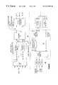
- FIG. 2illustrates a schematic block diagram of the video decoder 20 , the output control module 21 and the DAC module 23 .
- the video decoder 20includes a multiplexor 50 , an analog digital conversion module 54 , a comb filter 52 , and a YCrCb processing module 56 .
- the analog-to-digital conversion module 54includes two analog-to-digital converters 58 and 60 and two decimation filters 62 and 64 .
- the multiplexor 50is operably coupled to receive the video input signals 28 and, based on a select signal, provides the selected video signals to the analog-to-digital conversion module 54 .
- the A/D conversion module 54receives the analog signals, converts them to digital signals, and then filters them to produce digital video signals 78 .
- the comb filter 52further filters the digital video signal 78 to produce a Y component digital signal 74 and a C component digital signal 76 .
- the Y and C component digital signals 74 and 76are provided to the YCrCb processing module 56 and to an input switching matrix 68 of the output control module 21 .
- the YCrCb processing module 56processes the Y and C component digital signals 74 and 76 to produce YCrCb video data.
- the output control module 21includes a YCrCb to YUV converter 66 , the input switching matrix 68 , up sample module 70 , and an output switching matrix 72 .
- the YCrCb to YUV conversion module 66is operably coupled to receive the YCrCb output from the processing module 56 .
- the YUV resultant datais provided to the input switching matrix 68 .
- the input switching matrix 68which may include a plurality of multiplexors, selects the Y and C component digital signals 74 and 76 to be provided to the up sampling module 70 .
- the commandscould instruct the input switching matrix 68 to provide the YUV data provided by the YCrCb to YUV converter 66 to the up sampling module.
- input command signalsmay cause the input switching matrix 68 to provide a combination of the Y and C component digital signals and the YUV signals to the up sampling module 70 , which changes the sampling frequency of the signals to match the desired output sampling frequencies.
- the output switching matrix 72which may include a plurality of multiplexors, receives the output of the up sampling module 70 and the YUV video data 80 from the video encoder 22 . Based on output commands, the output switching matrix 72 provides the output of the up sampling module 70 , the YUV video data 80 , or a combination thereof to the digital-to-analog conversion module 23 . As shown, the DAC module 23 includes three separate digital-to-analog converters.
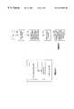
- FIG. 3illustrates a schematic block diagram of a video system 90 that includes a processing module 92 and memory 94 .
- the processing module 92may be a single processing entity or a plurality of processing entities. Such a processing entity may be a microprocessor, microcomputer, microcontroller, central processing unit, digital signal processor, state machine, logic circuitry, and/or any device that manipulates information based on operational instructions.
- the memory 94may be a single memory device or a plurality of memory devices. Such a memory device may be a read-only memory, random access memory, floppy disk memory, hard disk memory, reprogrammable memory, magnetic tape memory, DVD memory, and/or any device that stores digital information. Note that if the processing module implements one or more of its functions using a state machine or logic circuitry, the memory storing the corresponding operational instructions is embedded within the circuitry that comprises the state machine and/or logic circuitry.
- the memory 94stores a plurality of operational instructions that, when executed by the processing module 92 , causes the processing module to processes incoming video to a plurality of output video sources.
- the operational instructions stored in memory 94 and executed by processing module 92will be discussed in further detail with reference to FIG. 4 .
- FIG. 4illustrates a logic diagram of a method for processing incoming video signals through a plurality of output video sources.
- the processbegins at step 100 where at least one input video signal is received.
- the processthen proceeds to step 102 where a Y component digital signal and a C component digital signal is produced from the received input signal.
- the processthen proceeds to step 104 where an output command is interpreted.
- the output commandmay be obtained via accessing a default register, receiving a user input, and/or determining system configuration.
- the determination of system configurationmay include determining whether a television 30 monitor is connected to a composite video output or the S video output. If coupled, the output command may cause the bypassing of the graphics controller, such that the video signals are provided directly from the video decoder to the output control module.
- the processthen proceeds to step 106 where the Y and C component digital signals are converted into a composite video output and an S video output.
- the Y Cr Cb datamay be received.
- itis processed to produce an encoded composite video signal, encoded Y component video data, and an encoded C component video data
- the encoded composite video data, encoded Y component video data, and encoded C component video dataare then processed to generate the composite video output and the S video output.
- the Y Cr Cb datamay be representative of graphics data and/or processed video signals.
- RGB datamay be generated from the Y Cr Cb data. In this instance, the RGB data would then be provided to a computer monitor such that a single video source may be provided to a plurality of output sources without undue processing by the video graphics processing.
- the preceding discussionhas presented a method and apparatus for receiving a video input signal and providing it to one or more of a plurality of video sources.
- the present inventionprovides at least one graphics controller bypass path such that the graphics controller does process the video data prior to being outputted. By avoiding utilization of the graphics controller, processing resources of the graphics controller are preserved.
Landscapes
- Engineering & Computer Science (AREA)
- Physics & Mathematics (AREA)
- Computer Hardware Design (AREA)
- General Physics & Mathematics (AREA)
- Theoretical Computer Science (AREA)
- Multimedia (AREA)
- Signal Processing (AREA)
- Controls And Circuits For Display Device (AREA)
Abstract
Description
Claims (18)
Priority Applications (1)
| Application Number | Priority Date | Filing Date | Title |
|---|---|---|---|
| US09/183,884US6327002B1 (en) | 1998-10-30 | 1998-10-30 | Method and apparatus for video signal processing in a video system |
Applications Claiming Priority (1)
| Application Number | Priority Date | Filing Date | Title |
|---|---|---|---|
| US09/183,884US6327002B1 (en) | 1998-10-30 | 1998-10-30 | Method and apparatus for video signal processing in a video system |
Publications (1)
| Publication Number | Publication Date |
|---|---|
| US6327002B1true US6327002B1 (en) | 2001-12-04 |
Family
ID=22674713
Family Applications (1)
| Application Number | Title | Priority Date | Filing Date |
|---|---|---|---|
| US09/183,884Expired - LifetimeUS6327002B1 (en) | 1998-10-30 | 1998-10-30 | Method and apparatus for video signal processing in a video system |
Country Status (1)
| Country | Link |
|---|---|
| US (1) | US6327002B1 (en) |
Cited By (25)
| Publication number | Priority date | Publication date | Assignee | Title |
|---|---|---|---|---|
| US6567770B2 (en)* | 1998-04-23 | 2003-05-20 | Micron Technology, Inc. | Remote semiconductor microscopy |
| US20040190086A1 (en)* | 2003-03-28 | 2004-09-30 | Realtek Semiconductor Corp. | Multi-function peripheral |
| US6819305B2 (en)* | 1999-01-28 | 2004-11-16 | Conexant Systems, Inc. | Method and apparatus for detection of a video display device |
| US20050007373A1 (en)* | 2003-07-08 | 2005-01-13 | Lim Ricardo Te | Graphics controller providing flexible access to a graphics display device by a host |
| US20050024369A1 (en)* | 1998-11-09 | 2005-02-03 | Broadcom Corporation | Video and graphics system with a single-port RAM |
| US20050128205A1 (en)* | 2003-12-15 | 2005-06-16 | Raymond Chow | Graphics display controller providing enhanced read/write efficiency for interfacing with a RAM-integrated graphics display device |
| US6914638B2 (en)* | 2000-12-20 | 2005-07-05 | Intel Corporation | Three-dimensional enhancement processing for television broadcasting signals |
| US20050174492A1 (en)* | 2004-02-05 | 2005-08-11 | Brad Delanghe | Method and system for data compression for storage of 3D comb filter data |
| US20050219415A1 (en)* | 2004-04-02 | 2005-10-06 | Nvidia Corporation | Supersampling of digital video output for multiple analog display formats |
| US20050231526A1 (en)* | 1998-11-09 | 2005-10-20 | Broadcom Corporation | Graphics display system with anti-aliased text and graphics feature |
| US20060125963A1 (en)* | 2004-12-13 | 2006-06-15 | Lg Electronics Inc. | Personal video recorder system and method for reproducing a broadcasting signal in the system |
| US7071944B2 (en) | 1998-11-09 | 2006-07-04 | Broadcom Corporation | Video and graphics system with parallel processing of graphics windows |
| US7110006B2 (en)* | 1998-11-09 | 2006-09-19 | Broadcom Corporation | Video, audio and graphics decode, composite and display system |
| US20070067498A1 (en)* | 2005-08-12 | 2007-03-22 | Lippert Kurt J | System and method for information handling system video input and output |
| US7256790B2 (en) | 1998-11-09 | 2007-08-14 | Broadcom Corporation | Video and graphics system with MPEG specific data transfer commands |
| US7277099B2 (en) | 1998-11-09 | 2007-10-02 | Broadcom Corporation | Video and graphics system with an MPEG video decoder for concurrent multi-row decoding |
| US20080018663A1 (en)* | 2006-07-18 | 2008-01-24 | Sitronix Technology Corp. | Access structure for internal memory of driving control elements |
| US20080232460A1 (en)* | 2007-03-23 | 2008-09-25 | Ati Technologies, Inc. | Video decoder with adaptive outputs |
| US20080232704A1 (en)* | 2007-03-23 | 2008-09-25 | Ati Technologies Ulc | Video decoder with adaptive outputs |
| US20080266459A1 (en)* | 2007-04-26 | 2008-10-30 | Mark Butterworth | Multiple format video display |
| US7446774B1 (en) | 1998-11-09 | 2008-11-04 | Broadcom Corporation | Video and graphics system with an integrated system bridge controller |
| US20080305870A1 (en)* | 2007-06-05 | 2008-12-11 | Henderson Byron M | Interactive display |
| US7991049B2 (en) | 1998-11-09 | 2011-08-02 | Broadcom Corporation | Video and graphics system with video scaling |
| US8063916B2 (en) | 2003-10-22 | 2011-11-22 | Broadcom Corporation | Graphics layer reduction for video composition |
| US8199154B2 (en) | 1998-11-09 | 2012-06-12 | Broadcom Corporation | Low resolution graphics mode support using window descriptors |
Citations (9)
| Publication number | Priority date | Publication date | Assignee | Title |
|---|---|---|---|---|
| US5650831A (en)* | 1995-07-17 | 1997-07-22 | Gateway 2000, Inc. | Adjustable power remote control drive |
| US5835729A (en)* | 1996-09-13 | 1998-11-10 | Silicon Graphics, Inc. | Circuit to separate and combine color space component data of a video image |
| US5844629A (en)* | 1996-05-30 | 1998-12-01 | Analog Devices, Inc. | Digital-to-analog video encoder with novel equalization |
| US5850266A (en)* | 1995-12-22 | 1998-12-15 | Cirrus Logic, Inc. | Video port interface supporting multiple data formats |
| US5982453A (en)* | 1996-09-25 | 1999-11-09 | Thomson Consumer Electronics, Inc. | Reduction of visibility of spurious signals in video |
| US6008858A (en)* | 1996-12-06 | 1999-12-28 | Ati Technologies, Inc | Video timing generation |
| US6091429A (en)* | 1991-11-21 | 2000-07-18 | Imagination Technologies Limited | Video/graphics memory system |
| US6098174A (en)* | 1998-08-03 | 2000-08-01 | Cirrus Logic, Inc. | Power control circuitry for use in a computer system and systems using the same |
| US6172712B1 (en)* | 1997-12-31 | 2001-01-09 | Intermec Ip Corp. | Television with hard disk drive |
- 1998
- 1998-10-30USUS09/183,884patent/US6327002B1/ennot_activeExpired - Lifetime
Patent Citations (9)
| Publication number | Priority date | Publication date | Assignee | Title |
|---|---|---|---|---|
| US6091429A (en)* | 1991-11-21 | 2000-07-18 | Imagination Technologies Limited | Video/graphics memory system |
| US5650831A (en)* | 1995-07-17 | 1997-07-22 | Gateway 2000, Inc. | Adjustable power remote control drive |
| US5850266A (en)* | 1995-12-22 | 1998-12-15 | Cirrus Logic, Inc. | Video port interface supporting multiple data formats |
| US5844629A (en)* | 1996-05-30 | 1998-12-01 | Analog Devices, Inc. | Digital-to-analog video encoder with novel equalization |
| US5835729A (en)* | 1996-09-13 | 1998-11-10 | Silicon Graphics, Inc. | Circuit to separate and combine color space component data of a video image |
| US5982453A (en)* | 1996-09-25 | 1999-11-09 | Thomson Consumer Electronics, Inc. | Reduction of visibility of spurious signals in video |
| US6008858A (en)* | 1996-12-06 | 1999-12-28 | Ati Technologies, Inc | Video timing generation |
| US6172712B1 (en)* | 1997-12-31 | 2001-01-09 | Intermec Ip Corp. | Television with hard disk drive |
| US6098174A (en)* | 1998-08-03 | 2000-08-01 | Cirrus Logic, Inc. | Power control circuitry for use in a computer system and systems using the same |
Cited By (54)
| Publication number | Priority date | Publication date | Assignee | Title |
|---|---|---|---|---|
| US6859760B2 (en) | 1998-04-23 | 2005-02-22 | Micron Technology, Inc. | Remote semiconductor microscopy |
| US6567770B2 (en)* | 1998-04-23 | 2003-05-20 | Micron Technology, Inc. | Remote semiconductor microscopy |
| US7310104B2 (en) | 1998-11-09 | 2007-12-18 | Broadcom Corporation | Graphics display system with anti-flutter filtering and vertical scaling feature |
| US7598962B2 (en) | 1998-11-09 | 2009-10-06 | Broadcom Corporation | Graphics display system with window descriptors |
| US20050024369A1 (en)* | 1998-11-09 | 2005-02-03 | Broadcom Corporation | Video and graphics system with a single-port RAM |
| US9575665B2 (en) | 1998-11-09 | 2017-02-21 | Broadcom Corporation | Graphics display system with unified memory architecture |
| US9077997B2 (en) | 1998-11-09 | 2015-07-07 | Broadcom Corporation | Graphics display system with unified memory architecture |
| US8848792B2 (en) | 1998-11-09 | 2014-09-30 | Broadcom Corporation | Video and graphics system with video scaling |
| US8493415B2 (en) | 1998-11-09 | 2013-07-23 | Broadcom Corporation | Graphics display system with video scaler |
| US8199154B2 (en) | 1998-11-09 | 2012-06-12 | Broadcom Corporation | Low resolution graphics mode support using window descriptors |
| US20050231526A1 (en)* | 1998-11-09 | 2005-10-20 | Broadcom Corporation | Graphics display system with anti-aliased text and graphics feature |
| US7002602B2 (en) | 1998-11-09 | 2006-02-21 | Broadcom Corporation | Apparatus and method for blending graphics and video surfaces |
| US7057622B2 (en) | 1998-11-09 | 2006-06-06 | Broadcom Corporation | Graphics display system with line buffer control scheme |
| US7991049B2 (en) | 1998-11-09 | 2011-08-02 | Broadcom Corporation | Video and graphics system with video scaling |
| US7365752B2 (en) | 1998-11-09 | 2008-04-29 | Broadcom Corporation | Video and graphics system with a single-port RAM |
| US7920151B2 (en) | 1998-11-09 | 2011-04-05 | Broadcom Corporation | Graphics display system with video scaler |
| US7098930B2 (en) | 1998-11-09 | 2006-08-29 | Broadcom Corporation | Graphics display system with anti-flutter filtering and vertical scaling feature |
| US7911483B1 (en) | 1998-11-09 | 2011-03-22 | Broadcom Corporation | Graphics display system with window soft horizontal scrolling mechanism |
| US7110006B2 (en)* | 1998-11-09 | 2006-09-19 | Broadcom Corporation | Video, audio and graphics decode, composite and display system |
| US7184058B2 (en) | 1998-11-09 | 2007-02-27 | Broadcom Corporation | Graphics display system with anti-aliased text and graphics feature |
| US7538783B2 (en) | 1998-11-09 | 2009-05-26 | Broadcom Corporation | Graphics display system with video scaler |
| US7530027B2 (en) | 1998-11-09 | 2009-05-05 | Broadcom Corporation | Graphics display system with graphics window control mechanism |
| US7209992B2 (en) | 1998-11-09 | 2007-04-24 | Broadcom Corporation | Graphics display system with unified memory architecture |
| US7227582B2 (en) | 1998-11-09 | 2007-06-05 | Broadcom Corporation | Graphics display system with video synchronization feature |
| US7256790B2 (en) | 1998-11-09 | 2007-08-14 | Broadcom Corporation | Video and graphics system with MPEG specific data transfer commands |
| US7277099B2 (en) | 1998-11-09 | 2007-10-02 | Broadcom Corporation | Video and graphics system with an MPEG video decoder for concurrent multi-row decoding |
| US7446774B1 (en) | 1998-11-09 | 2008-11-04 | Broadcom Corporation | Video and graphics system with an integrated system bridge controller |
| US7071944B2 (en) | 1998-11-09 | 2006-07-04 | Broadcom Corporation | Video and graphics system with parallel processing of graphics windows |
| US6819305B2 (en)* | 1999-01-28 | 2004-11-16 | Conexant Systems, Inc. | Method and apparatus for detection of a video display device |
| US6914638B2 (en)* | 2000-12-20 | 2005-07-05 | Intel Corporation | Three-dimensional enhancement processing for television broadcasting signals |
| US20040190086A1 (en)* | 2003-03-28 | 2004-09-30 | Realtek Semiconductor Corp. | Multi-function peripheral |
| US20050007373A1 (en)* | 2003-07-08 | 2005-01-13 | Lim Ricardo Te | Graphics controller providing flexible access to a graphics display device by a host |
| US7075543B2 (en)* | 2003-07-08 | 2006-07-11 | Seiko Epson Corporation | Graphics controller providing flexible access to a graphics display device by a host |
| US8063916B2 (en) | 2003-10-22 | 2011-11-22 | Broadcom Corporation | Graphics layer reduction for video composition |
| US7102645B2 (en) | 2003-12-15 | 2006-09-05 | Seiko Epson Corporation | Graphics display controller providing enhanced read/write efficiency for interfacing with a RAM-integrated graphics display device |
| US20050128205A1 (en)* | 2003-12-15 | 2005-06-16 | Raymond Chow | Graphics display controller providing enhanced read/write efficiency for interfacing with a RAM-integrated graphics display device |
| US20050174492A1 (en)* | 2004-02-05 | 2005-08-11 | Brad Delanghe | Method and system for data compression for storage of 3D comb filter data |
| US7492415B2 (en)* | 2004-02-05 | 2009-02-17 | Broadcom Corporation | Method and system for data compression for storage of 3D comb filter data |
| WO2005098813A3 (en)* | 2004-04-02 | 2007-03-08 | Nvidia Corp | Supersampling of digital video output for multiple analog display formats |
| CN100583947C (en)* | 2004-04-02 | 2010-01-20 | 辉达公司 | Apparatus and method for converting digital pixel signal into analog signal having target format |
| US20050219415A1 (en)* | 2004-04-02 | 2005-10-06 | Nvidia Corporation | Supersampling of digital video output for multiple analog display formats |
| US7460175B2 (en)* | 2004-04-02 | 2008-12-02 | Nvidia Corporation | Supersampling of digital video output for multiple analog display formats |
| CN1798348B (en)* | 2004-12-13 | 2010-05-12 | Lg电子株式会社 | Personal video recorder system and method for reproducing a signal in the system |
| US20060125963A1 (en)* | 2004-12-13 | 2006-06-15 | Lg Electronics Inc. | Personal video recorder system and method for reproducing a broadcasting signal in the system |
| US20070067498A1 (en)* | 2005-08-12 | 2007-03-22 | Lippert Kurt J | System and method for information handling system video input and output |
| US20080018663A1 (en)* | 2006-07-18 | 2008-01-24 | Sitronix Technology Corp. | Access structure for internal memory of driving control elements |
| US8139632B2 (en) | 2007-03-23 | 2012-03-20 | Advanced Micro Devices, Inc. | Video decoder with adaptive outputs |
| US8537890B2 (en) | 2007-03-23 | 2013-09-17 | Ati Technologies Ulc | Video decoder with adaptive outputs |
| US20080232704A1 (en)* | 2007-03-23 | 2008-09-25 | Ati Technologies Ulc | Video decoder with adaptive outputs |
| US20080232460A1 (en)* | 2007-03-23 | 2008-09-25 | Ati Technologies, Inc. | Video decoder with adaptive outputs |
| US20080266459A1 (en)* | 2007-04-26 | 2008-10-30 | Mark Butterworth | Multiple format video display |
| WO2008151296A1 (en)* | 2007-06-05 | 2008-12-11 | Henderson Byron M | Interactive display |
| US8465365B2 (en) | 2007-06-05 | 2013-06-18 | Game Changer, LLC | Interactive multi-screen display |
| US20080305870A1 (en)* | 2007-06-05 | 2008-12-11 | Henderson Byron M | Interactive display |
Similar Documents
| Publication | Publication Date | Title |
|---|---|---|
| US6327002B1 (en) | Method and apparatus for video signal processing in a video system | |
| US6177946B1 (en) | Method and apparatus for processing video data and graphics data by a graphic controller | |
| US5664218A (en) | Integrated multimedia input/output processor | |
| US5185666A (en) | Digitized film image processing system with bordered split screen display | |
| US5864345A (en) | Table-based color conversion to different RGB16 formats | |
| US20090310947A1 (en) | Apparatus and Method for Processing and Blending Multiple Heterogeneous Video Sources for Video Output | |
| EP0821340B1 (en) | Video signal processing apparatus for converting video signals to conform to a display device | |
| JPH07236151A (en) | Digital video switcher | |
| KR20000041319A (en) | Apparatus for processing color signal of image signal processing system | |
| US6075573A (en) | Method and apparatus for converting luminance-chrominance color space signals to RGB color space signals using shared predictive and compensative transformation codes for chrominance components | |
| JPH05344435A (en) | Mute circuit | |
| US5917467A (en) | PC card system having video input-output functions | |
| TW200522726A (en) | Connection device capable of mixing RGB graphic signal and YUV video signal and related method | |
| JPH01252091A (en) | Digital circuit of video tape recorder | |
| US5475436A (en) | Sampling rate converting system for converting the sampling rate of a video signal | |
| US20020105594A1 (en) | Signal processing apparatus | |
| JPH0437464B2 (en) | ||
| JPH09200797A (en) | Device for separating digital composite video signal into components | |
| JP3442953B2 (en) | Clipping equipment | |
| CN2548376Y (en) | Multimedia liquid crystal television set with VGA display function | |
| JP2004056719A (en) | Image signal input/output terminal for image processing apparatus | |
| JP3449950B2 (en) | Video signal standard converter | |
| JP2763336B2 (en) | Color information signal processing device | |
| US20060005134A1 (en) | Information processing apparatus and display control method thereof | |
| JPH0518515B2 (en) |
Legal Events
| Date | Code | Title | Description |
|---|---|---|---|
| AS | Assignment | Owner name:ATI INTERNATIONAL, INC., BARBADOS Free format text:ASSIGNMENT OF ASSIGNORS INTEREST;ASSIGNORS:RINALDI, ANTONIO;CARTER, COLLIS QUINN;REEL/FRAME:009600/0993 Effective date:19981022 | |
| STCF | Information on status: patent grant | Free format text:PATENTED CASE | |
| FPAY | Fee payment | Year of fee payment:4 | |
| FPAY | Fee payment | Year of fee payment:8 | |
| AS | Assignment | Owner name:ATI INTERNATIONAL SRL, BARBADOS Free format text:ASSIGNMENT OF ASSIGNORS INTEREST;ASSIGNORS:RINALDI, ANTONIO;CARTER, COLLIS QUINN;REEL/FRAME:023373/0485 Effective date:19981022 | |
| AS | Assignment | Owner name:ATI TECHNOLOGIES ULC, CANADA Free format text:ASSIGNMENT OF ASSIGNORS INTEREST;ASSIGNOR:ATI INTERNATIONAL SRL;REEL/FRAME:023574/0593 Effective date:20091118 Owner name:ATI TECHNOLOGIES ULC,CANADA Free format text:ASSIGNMENT OF ASSIGNORS INTEREST;ASSIGNOR:ATI INTERNATIONAL SRL;REEL/FRAME:023574/0593 Effective date:20091118 | |
| FPAY | Fee payment | Year of fee payment:12 |