US6325978B1 - Oxygen monitoring and apparatus - Google Patents
Oxygen monitoring and apparatusDownload PDFInfo
- Publication number
- US6325978B1 US6325978B1US09/128,918US12891898AUS6325978B1US 6325978 B1US6325978 B1US 6325978B1US 12891898 AUS12891898 AUS 12891898AUS 6325978 B1US6325978 B1US 6325978B1
- Authority
- US
- United States
- Prior art keywords
- monitoring apparatus
- oxygen monitoring
- oxygen
- transducer
- component
- Prior art date
- Legal status (The legal status is an assumption and is not a legal conclusion. Google has not performed a legal analysis and makes no representation as to the accuracy of the status listed.)
- Expired - Lifetime
Links
Images


Classifications
- A—HUMAN NECESSITIES
- A61—MEDICAL OR VETERINARY SCIENCE; HYGIENE
- A61B—DIAGNOSIS; SURGERY; IDENTIFICATION
- A61B5/00—Measuring for diagnostic purposes; Identification of persons
- A61B5/08—Measuring devices for evaluating the respiratory organs
- A61B5/097—Devices for facilitating collection of breath or for directing breath into or through measuring devices
- A—HUMAN NECESSITIES
- A61—MEDICAL OR VETERINARY SCIENCE; HYGIENE
- A61B—DIAGNOSIS; SURGERY; IDENTIFICATION
- A61B5/00—Measuring for diagnostic purposes; Identification of persons
- A61B5/08—Measuring devices for evaluating the respiratory organs
- A61B5/083—Measuring rate of metabolism by using breath test, e.g. measuring rate of oxygen consumption
- A61B5/0833—Measuring rate of oxygen consumption
- G—PHYSICS
- G01—MEASURING; TESTING
- G01N—INVESTIGATING OR ANALYSING MATERIALS BY DETERMINING THEIR CHEMICAL OR PHYSICAL PROPERTIES
- G01N21/00—Investigating or analysing materials by the use of optical means, i.e. using sub-millimetre waves, infrared, visible or ultraviolet light
- G01N21/62—Systems in which the material investigated is excited whereby it emits light or causes a change in wavelength of the incident light
- G01N21/63—Systems in which the material investigated is excited whereby it emits light or causes a change in wavelength of the incident light optically excited
- G01N21/64—Fluorescence; Phosphorescence
- G01N21/6428—Measuring fluorescence of fluorescent products of reactions or of fluorochrome labelled reactive substances, e.g. measuring quenching effects, using measuring "optrodes"
- A—HUMAN NECESSITIES
- A61—MEDICAL OR VETERINARY SCIENCE; HYGIENE
- A61B—DIAGNOSIS; SURGERY; IDENTIFICATION
- A61B2562/00—Details of sensors; Constructional details of sensor housings or probes; Accessories for sensors
- A61B2562/02—Details of sensors specially adapted for in-vivo measurements
- Y—GENERAL TAGGING OF NEW TECHNOLOGICAL DEVELOPMENTS; GENERAL TAGGING OF CROSS-SECTIONAL TECHNOLOGIES SPANNING OVER SEVERAL SECTIONS OF THE IPC; TECHNICAL SUBJECTS COVERED BY FORMER USPC CROSS-REFERENCE ART COLLECTIONS [XRACs] AND DIGESTS
- Y10—TECHNICAL SUBJECTS COVERED BY FORMER USPC
- Y10T—TECHNICAL SUBJECTS COVERED BY FORMER US CLASSIFICATION
- Y10T436/00—Chemistry: analytical and immunological testing
- Y10T436/20—Oxygen containing
- Y10T436/207497—Molecular oxygen
- Y10T436/209163—Dissolved or trace oxygen or oxygen content of a sealed environment
Definitions
- the present inventionrelates to the monitoring of oxygen concentration and, more particularly, to novel, improved methods and apparatus for monitoring the concentration of oxygen in respiratory and other gases and to components of and controls for apparatus as just characterized.
- the present inventionrelates to methods of manufacturing airway adapters designed for use in on-airway applications of the invention.
- the present inventionrelates to novel sensors which include an oxygen quenchable luminescable compound and methods for manufacturing sensors of the character.
- arterial puncturehas inherent limitations: (1) arterial puncture requires a skilled health care provider and it carries a significant degree of patient discomfort and risk, (2) handling the blood is a potential health hazard to the health care provider, (3) significant delays are often encountered before results are obtained, and (4) measurements can only be made intermittently.
- Non-invasive methods for estimating blood gas levelsare available. Such methods include the use of capnography (CO 2 analysis). These methods employ fast gas analyzers at the patient's airway and give a graphic portrayal of breath-by-breath gas concentrations and, therefore, can measure the peak exhaled (end tidal) concentrations of the respective respired gases. Although gradients can occur between the actual arterial blood gas levels and the end tidal values, this type of monitoring is often used as a first order approximation of the arterial blood gas values.
- CO 2 analysiscapnography
- Transcutaneous sensorsmeasure tissue pO 2 and pCO 2 diffused through the heated skin surface. This type of sensor has a number of practical limitations including a slow speed of response and difficulty of use.
- Pulse oximetryis widely used to measure the percentage of hemoglobin that is saturated with oxygen. Unfortunately, it does not measure the amount of dissolved oxygen present nor the amount of oxygen.carried by the blood when hemoglobin levels are reduced. This is important because low hemoglobin levels are found when there is a significant blood loss or when there is insufficient red blood cell information.
- pulse oximeter readingsare specific to the point of contact, which is typically the finger or ear lobe, and may not reflect the oxygen level of vital organs during conditions such as shock or hypothermia.
- Oxygraphymeasures the approximate concentration of oxygen in the vital organs on a breath-by-breath basis and can quickly detect imminent hypoxemia due to decreasing alveolar oxygen concentration. For example, during hypoventilation, end tidal oxygen concentration changes more rapidly than does end tidal carbon dioxide. During the same conditions, pulse oximetry takes considerably longer to respond. Fast oxygen analysis (oxygraphy) can also readily detect inadvertent administration of hypoxic gas mixtures.
- Oxygraphyreflects the balance of alveolar O 2 available during inspiration minus the O 2 uptake secondary to pulmonary perfusion. An increasing difference between inspiratory and end tidal oxygen values is a rapid indicator of a supply/demand imbalance which could be a result of changes in ventilation, diffusion, perfusion and/or metabolism of the patient. This imbalance must be quickly corrected because failure to meet oxygen demand is the most common cause of organ failure, cardiac arrest, and brain damage. Oxygraphy provides the earliest warning of the development of an impending hypoxic episode.
- Oxygraphyhas also been shown to be effective in diagnosing hypoglycemic or septic shock, air embolism, hyperthermia, excessive PEEP, CPPR efficacy, and even cardiac arrest.
- oxygraphyis useful in providing a routine monitor of preoxygenation (denitrogenation). It especially contributes to patient safety by detecting human errors, equipment failures, disconnections, misconnections, anesthesia overdoses, and esophageal intubations.
- a metabolic measurementincludes determination of a patient's energy requirements (in calories per day) and respiratory quotient (RQ).
- Interest in the measurement of caloric requirementshas closely paralleled the development of nutritional support. For example, the ability to intravenously provide all the necessary nutrition to critically ill patients has only been accomplished within the last 25 years. Along with the realization that we need to feed patients, has come the need to know how much to feed them, what kind of nutrients (carbohydrates, lipids, protein) to feed them, and in what ratio the nutrients need to be supplied.
- the only true way to measure the caloric requirements of patients and to provide a non-invasive quality assessment of their response to nutritionis with indirect calorimetry. Airway O 2 consumption and CO 2 production can be measured non-invasively and provide a basis for the computations needed for a measurement of indirect calorimetry, a direct measurement of the metabolic status of the patient, and the patients' respiratory quotient.
- On-airway (mainstream) monitoring of oxygenhas the potential to solve all of the above problems, especially when breath by breath monitoring oxygen consumption measurements are to be made.
- most of the available fast oxygen sensorsare simply too big, too heavy, too fragile, and/or otherwise not suited to be placed in line with a patient's breathing tube.
- electrochemical sensorsSome of the most widely used are electrochemical sensors. These fall into two basic categories: polarographic cells and galvanic cells. These cells produce an electric current proportional to the number of oxygen molecules which diffuse across a membrane.
- the advantages of these types of sensorsare simplicity and low cost.
- the disadvantagesinclude limited lifetime (chemistry depletes) and slow response (not breath-by-breath).
- these cellshave demonstrated sensitivity to certain anesthetic agents, which introduces inaccuracies into the oxygen concentration measurement.
- this type of sensoris too large to attach to the patient airway.
- paramagnetic typeThis sensor uses the strong magnetic property of oxygen as a sensing mechanism.
- the static typeis a dumbbell assembly suspended between the poles of a permanent magnet. The magnetic forces of the surrounding oxygen molecules cause a torsional rotation of the dumbbell which can be sensed optically and employed as a measure of oxygen concentration.
- the dynamic type(see U.S. Pat. No. 4,633,705) uses a magneto-acoustic approach. This requires a gas sample and a reference gas that are mixed within an electromagnetic field. When the field is switched on and off, a pressure signal proportional to the oxygen content is generated. The signal can be detected by a differential microphone.
- the advantages of the paramagnetic sensorare good linearity and stability.
- the dynamic typeis inherently faster responding that the static type. Both types are subject to mechanical vibration, and the dynamic type has the disadvantage of requiring a reference gas. Neither type is suitable for on-airway applications.
- Zirconium oxide cellsare frequently used in the automotive industry to measure oxygen concentration.
- the cellis constructed from a solid electrolyte tube covered by platinum electrodes. When heated to approximately 800 degrees C., a voltage proportional to the Icgarithm of the ratio between a sample gas and a reference gas is generated.
- the advantage of this sensorare wide dynamic range, very fast response, and simplicity.
- the high cell temperatureis clearly a disadvantage as is power consumption. Also, the cell is degraded in the presence of anesthetic agents. Clearly, this type of cell cannot be used on a patient airway.
- Ultraviolet absorptionuses the principle that oxygen exhibits absorption properties in the ultraviolet part of the electromagnetic spectrum (about 147 nm). This technique has been used in several medical applications but has never been reduced to commercial viability. There are numerous technical difficulties which make this a difficult technique for on-airway applications.
- Mass spectrometersspread ionized gas molecules into a detectable spectrum according to their mass-to-charge ratios and can accordingly be used to measure oxygen concentration. These instruments are generally large assemblies with ionizing magnets and high vacuum pumps.
- the advantages of mass spectrometersinclude high accuracy, multi-gas analysis capability, and rapid response.
- the disadvantagesinclude high cost, high power consumption, and large size. Mass spectrometers are not suitable for on-airway applications.
- Raman scattering spectrometerscan also be used to measure oxygen concentration. These devices respond to photons emitted by the collision of a photon with an oxygen molecule. A photon from a high-power laser loses energy to the oxygen molecule and is re-emitted at a lower energy and frequency. The number of photons re-emitted at the oxygen scattering wavelength is proportional to the number of oxygen molecules present. Like mass spectrometers, Raman spectrometers have multi gas analysis capability and rapid response time. Disadvantages include large size and power consumption. Therefore, Raman scattering photometers are not suitable for on-airway applications.
- Visible light absorption spectrometers(as described in U.S. Pat. Nos. 5,625,189 and 5,570,697) utilize semiconductor lasers that emit light near 760 nm, an area of the spectrum comprised of weak absorption lines for oxygen. With sophisticated circuitry, the laser can be thermally and/or electronically tuned to the appropriate absorption bands. The amount of energy absorbed is proportional to the number of oxygen molecules present.
- the advantages of this systemare precision, fast response, and no consumable or moving parts.
- the disadvantagesinclude somewhat fragile optical components, sensitivity to ambient temperature shifts, and a long gas sample path length. While there have been attempts to utilize this technology in an on-airway configuration, no commercially viable instruments have so far been available.
- Luminescence quenchinghas also been proposed as a technique for measuring oxygen concentration.
- a sensor contacted by the gases being monitoredis excited into luminescence.
- This luminescenceis quenched by the oxygen in the monitored gases.
- the rate of quenchingis related to the partial pressure of oxygen in the monitored gases, and that parameter can accordingly be used to provide an indication of the oxygen in the monitored gases.
- End tidal oxygen analysisreflects arterial oxygen concentration.
- VO 2oxygen consumption
- RQrespiratory exchange ratio
- the novel sensor devices of the present inventionlocate a luminescent chemical in the patient airway. Modulated visible light excites the chemical and causes it to luminesce. The lifetime of the luminescence is proportional to the amount of oxygen present.
- a transducer containing a photodetector and associated electronic circuitrymeasures decay time and relates the measured parameter to the ambient oxygen partial pressure.
- the transducer deviceis small ( ⁇ 1 cubic inch), lightweight (less than 1 ounce), and does not contain moving parts. It utilizes visible light optoelectronics and consumes minimal power (system power less than 2 watts). The unit warms up in less than 30 seconds, which is advantageous in on-airway applications because of the need to take prompt remedial action if a change occurs in a patient's condition reflected in a change in respiratory oxygen concentration.
- the assemblydoes not require any significant optical alignment and is very rugged (capable of being dropped from 6 feet without effecting optical alignment or otherwise damaging the device).
- Yet another important advantage of the present inventionis that its principles can be employed to advantage in sidestream (sampling) type systems as well as in mainstream systems. This is important because some gas analysis systems, such as anesthetic analyzers, employ sidestream techniques to acquire the gas sample.
- a typical transducer unitis easy to calibrate, stable ( ⁇ 2 torr over 8 hours at a 21 percent oxygen concentration), and has a high resolution (0.1 torr) and a wide measurement range (oxygen concentrations of 0 to 100 percent). Response to changing oxygen concentrations is fast ( ⁇ 100 ms for oxygen concentrations of 10-90 percent at flow rates ⁇ 1 l/min).
- the transduceris not susceptible to interference from anesthetic agents, water vapor, nitrous oxide, carbon dioxide, or other gases and vapors apt to be present in the environment in which the system is used.
- the sensorcomprises a polymeric membrane in which a luminescable composition such as a porphyrin dye is dispersed.
- the sensor membraneis the mediator that brings about dye-oxygen interaction in a controlled fashion.
- the dyeis dispersed in the polymeric membrane, and oxygen diffuses through the polymer.
- the characteristics of the sensorare dependent upon the dye-polymer interaction and permeability and the solubility of oxygen in the polymer. Such characteristics include the sensitivity of response of the sensor to oxygen, the response time of the sensor to a change in oxygen concentration, and the measured values of phosphorescence intensity and decay time.
- the composition and molecular weight of the polymerdetermines the sensor characteristics.
- the film characteristicsdepend on the solvent that is used and conditions during casting or evaporation. If the dye is separately doped into the film from another solution, the solvent and conditions in the doping medium also affect the sensor characteristics.
- the sensor characteristicsdepend on the conditions of polymerization and such resultant polymer characteristics as degree of crosslinking and molecular weight.
- the luminescent chemical sensoris not toxic to the patient and is a part of a consumable (i.e., disposable) airway adapter weighing less than 0.5 ounce.
- the sensor shelf lifeis greater than one year and the operational life exceeds 100 hours.
- the cost of the consumable airway adapteris minimal.
- the oxygen monitoring system of the present inventionhas sufficient accuracy (1.0%), precision (0.01%), and response time ( ⁇ 100 ms) to monitor breath-by-breath oxygen concentrations.
- a related and important advantage of the present inventionis that the sensor is not sensitive to other gases found in the airway, including anesthetic agents, and is accordingly not excited into luminescence by those gases.
- the sensitivity of the sensor to temperature, flow rate, pressure and humidity changeis well understood; and algorithms which provide compensation for any errors due to these changes are incorporated in the signal processing circuits of the device.
- the senorcan be easily (and even automatically) calibrated to single point room air oxygen, which is important because of the lack of availability of calibration gases in certain settings.
- the deviceis so stable that recalibration is not required for at least eight hours.
- One embodiment of the present inventionemploys a single light source for exciting the luminescable composition of the sensor, a data detector on which light propagated from the luminescing composition falls as that luminescence is quenched by oxygen in the gases being monitored, and a reference detector for calibrating the data detector.
- a second embodiment of the present inventionemploys two sources of light for exciting the sensor into luminescence and a single (data) photodetector. This arrangement has the advantage of eliminating measurement errors attributable to differential drift between the data and reference signal processing circuits.
- Preferred embodiments of the visible light oxygen measurement transducers disclosed hereinemploy a novel sensor heater arrangement and a proportionalintegrated-differential (PID) heater control system for keeping the oxygen concentration sensor of the transducer precisely at a selected operating temperature.
- PIDproportionalintegrated-differential
- the oxygen concentration sensortakes the form of a thin film mounted in an airway adapter casing; and the sensor heater includes a highly conductive thermal capacitor for heating the sensor film.
- a novel assembly methodinsures that the sensor film is stretched over the thermal capacitor in the assembled airway adapter and that the thermal capacitor and sensor film are therefore in intimate physical contact. This further promotes the precision with which the sensor can be maintained at the selected temperature by guaranteeing a rapid transfer of heat between the thermal capacitor and the film so that the film temperature cannot drift to any appreciable extent from the selected operating temperature. This is reflected in an accurate oxygen concentration measurement.
- the thermal capacitor in the airway adapteris heated by way of a floating, thermally conductive heater component in the oxygen measurement transducer to which the airway adapter is removably assembled.
- the floating heater and thermal capacitorare so configured that the heater snaps into firm physical contact with the capacitor as the airway adapter is assembled to the transducer. This insures that there is intimate contact between, and an efficient transfer of heat from, the floating heater to the thermal capacitor.
- a thick film resistance heatercan be used to heat the transducer's floating heater element.
- This elementis preferably located on that side of the floating heater opposite the side contacted by the airway adapter thermal capacitor along with a temperature sensing component of the heater control system.
- the temperature sensoris incorporated in the PID control system for the thick film heater.
- the location of the oxygen concentration sensor in a replaceable, simple componentis an important feature of the present invention. This makes it possible to readily and inexpensively ensure that the system is sterile with respect to each patient being monitored by replacing the airway adapter between patients, avoiding the nondesireability (and perhaps the inability) to sterilize that system component.
- the provision of an airway adapter sensor and a separate signal-producing transduceralso has the practical advantage that a measurement of oxygen concentration can be made without interrupting either the ventilation of a patient, or any other procedure involving the use of the airway circuit. This is affected by installing the airway adapter in the airway circuit. When the time comes to make oxygen measurements, all that is required is the transducer be coupled to the airway adapter already in place.
- the adapterincludes a casing made from a thermally non-conductive polymer that defines a passage through which the gases to be analyzed flow.
- the airway adapter sensoris coupled to a transducer to generate a signal indicative of the oxygen concentration in the gases flowing through the airway adapter. Another important feature of the invention insures that the airway adapter and transducer are assembled in the correct orientation and that the airway adapter and transducer are securely assembled until deliberately separated by the system user.
- the signals generated by the novel oxygen-measurement transducers disclosed hereinmust be processed to remove noise and extract the luminescence decay time, which is the oxygen-sensitive parameter of interest.
- a lock-in amplifieris preferably employed for this purpose.
- the lock-in amplifieroutputs a signal which has a phase angle corresponding to the decay time of the excited, luminescent composition in the oxygen concentration sensor.
- the lock-in detection circuitryrejects noise and those components of the photodetector-generated signal which are not indicative of oxygen concentration. This noise reduction also allows a higher level of signal gain which, in turn, makes possible enhanced measurement precision while decreasing the level of the visible excitation. This reduces instability from photoaging of the sensor, increasing accuracy and useable life.
- the concentration of oxygen in the gases being monitoredis reflected in the quenching of an excited luminescent composition in the oxygen concentration sensor by oxygen diffusing into the sensor matrix.
- a sourceconsisting of a light-emitting diode (LED) produces visible exciting light which strikes the surface of the sensor film. Some of the light is absorbed by the luminescent chemical dye in the film whereupon it produces luminescent light at a second, shifted wavelength. All light directed toward the photodetector can potentially result in a signal.
- a suitable optical filter placed over the surface of the photodetectordiscriminates against all but the luminescent light, thereby ensuring that the photodetector is producing a signal related to oxygen concentration only.
- the goal of isolating the photodector from light which is not indicative of oxygen concentrationcan be furthered by a geometric relationship of the light source and photodetector as established by the configuration of an optical platform on which the light source and photodector are mounted. This geometric relationship places the photodetector at a location away from the specular reflection of the LED light off of the surface, further optimizing the ratio of luminescent light to other, stray or reflected light that might reach the detector.
- the novel oxygen-sensitive sensors employed in the present inventioninclude a luminescent composition, uniformly distributed over, and embedded in, a thin, porous polymer matrix, a scheme which ensures a fast sensor response time.
- Novel methods, disclosed herein, for manufacturing these sensorsare simpler than those heretofore proposed, give more reproducible results, and allow the matrix to be fabricated from a wide variety of polymers with desirable characteristics.
- a solution of the selected luminescent dyeis painted onto, or soaked into, a porous polymeric membrane or sandwiched between two membranes of the selected polymer. Due to the porous structure of the starting polymers, the films or membranes have the advantage that the molecules are embedded within microns of the gas-polymer interface and have fast response times.
- the starting materialis a thin polymeric membrane, batch processing of films of uniform composition and characteristics is facilitated.
- on-airway monitoringis a particularly advantageous application of the present invention.
- the principles of the present inventioncan, nevertheless, be advantageously employed in other gas monitoring techniques; notably, sidestream sampling, and can be used to monitor the oxygen concentration of other than respiratory gases.
- FIG. 1is a generally pictorial view of an on-line system for monitoring the oxygen concentration in a patient's breath; the system is constructed in accord with and embodies the principles of the present invention
- FIG. 2is an exploded view of an airway adapter and a complementary transducer employed in the FIG. 1 system; the airway adapter has a sensor for oxygen in respiratory gases flowing through the adapter and the transducer acts with the airway adapter to provide a signal indicative of the concentration of the oxygen in the monitored gases;
- FIG. 3is an exploded view which includes a perspective of the transducer and illustrates how the airway adapter is kept from being incorrectly assembled to the transducer;
- FIG. 4is an exploded view of the transducer showing the two components of the transducer casing and an assembly which includes the optical components of the transducer and a platform to which those components are mounted;
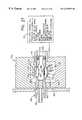
- FIG. 5is a transverse section through the airway adapter taken primarily to show the details of the oxygen sensor incorporated in the airway adapter and of a thermal capacitor included in the airway adapter to keep the temperature of the oxygen sensor constant;
- FIG. 6is a longitudinal section through the airway adapter and is provided to show: the passage through the adapter for the gases being monitored, the oxygen concentration sensor and thermal capacitor, and a window which transmits light to and from the oxygen sensor;
- FIGS. 7-10show the steps employed in installing the oxygen concentration sensor and the thermal capacitor in the casing of the airway adapter
- FIG. 11is a cross-sectional plan of the optical platform subassembly of the transducer; the optical components of the transducer are mounted to the platform of this subassembly;
- FIG. 12is a front view of the optical platform subassembly
- FIG. 13is a view of the transducer with one of the two casing components removed and certain components sectioned to show the internal components of and the optical paths in the transducer;
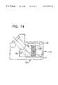
- FIG. 14is a generally pictorial view showing how a light source and a data detector in the transducer are so geometrically related by the platform of the optical subassembly that unwanted light which might affect the accuracy of the oxygen concentration signal outputted from the transducer is kept from reaching the detector;
- FIG. 15is a fragmentary exploded view of the FIG. 2 system components showing how the airway adapter fits the transducer;
- FIG. 16is a view similar to FIG. 15 but showing the airway adapter partially installed in the transducer with the thermal capacitor in the airway adapter coming into conductive heat transfer relationship with a complementary heater in the transducer;
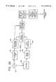
- FIG. 17shows, in block diagram form, the operating system of the FIG. 1 apparatus
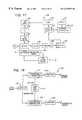
- FIG. 18is a block diagram of a lock-in amplifier circuit incorporated in the FIG. 17 operating system; the lock-in amplifier is employed to isolate from accompanying noise that component of the signal produced by a data detector in the transducer which is actually indicative of the concentration of oxygen in the gases being monitored;
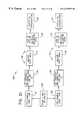
- FIG. 19is a block diagram of a heater control incorporated in the transducer; this control is employed in maintaining the sensor in the airway adapter at a constant operating temperature;
- FIG. 20is a block diagram showing how the signal propagated from the data detector of the FIG. 4 transducer is converted to a signal indicative of the concentration of oxygen in the gases being monitored;
- FIG. 21is a block diagram showing two different protocols for processing the detector-generated signal after that signal has been processed by the transducer electronics; one protocol is employed if there is a high concentration of oxygen in the gases being monitored, and the second protocol is employed if the oxygen concentration is low;
- FIG. 22is a view, similar to FIG. 13, of a second oxygen concentration monitoring transducer employing the principles of the present invention and consisting of an airway adapter and a transducer with dual light sources and a single detector;
- FIG. 23is a front view of an optical subassembly employed in the FIG. 22 transducer and consisting of an optical platform to which the dual light sources and detector are mounted;
- FIG. 24is a section through FIG. 23 optical assembly taken substantially along line 24 — 24 of FIG. 23;
- FIG. 25shows a sidestream sampling, oxygen concentration monitoring system employing the principles of the present invention
- FIG. 26illustrates a nasal canula component of the exemplary FIG. 25 system
- FIG. 27shows, in some detail, a sampling cell and a transducer of the FIG. 25 system; this figure also shows in block diagram for a signal processing and control unit of the system.
- FIG. 1depicts oxygen concentration monitoring apparatus 30 , which is constructed in accord with and embodies the principles of the present invention.
- the major components of apparatus 30include an online assembly 32 of a transducer 34 and an airway adapter 36 .
- the particular system 30 illustrated in FIG. 1,also includes a hand held control and display unit 38 which is connected to transducer 34 by a conventional electrical cable 40 .
- system 30is employed to monitor the concentration of oxygen in a patient's respiratory gases.
- airway adapter 36is connected in line between an endotracheal tube 42 inserted in the patient's trachea and the plumbing 44 of a mechanical ventilator (not shown).
- Airway adapter 36 and transducer 34cooperate to produce an electrical signal indicative of the oxygen concentration in the gases flowing from endotracheal tube 42 through airway adapter 36 to plumbing 44 .
- This signalis transmitted to unit 38 through cable 40 and converted to a numerical designation, which appears on the display array 46 of unit 38 .
- Transducer 34can be removed—for example, to facilitate or enable the movement of a patient—leaving airway adapter 36 in place to continue the vital flow of gases.
- System 30also has, in this regard, the advantage that there are no electrical components in the airway adapter. Hence, there are no potentially dangerous electrical connections to the airway adapter or exposure of a patient to electrical shock.
- the exemplary, illustrated airway adapter 36is a one-piece unit typically molded from Valox polycarbonate or a comparable polymer which is rugged and can be molded to close tolerances.
- An opaque materialis employed to keep ambient light from reaching a light sensitive sensor component 47 of the airway adapter through the walls of the airway adapter. Such extraneous light would adversely affect the accuracy of the oxygen concentration reading which the system is designed to provide.
- Airway adapter 36has a generally parallelepipedal center section 48 and hollow, cylindrical end sections 50 and 52 .
- Axially aligned passages 54 , 56 , and 58 respectively found in airway adapter elements 50 , 48 , and 52define a flow passage 60 extending from end-to-end through airway adapter 36 .
- end section 50 of airway adapter 36is configured as a male connector, and end section 52 is configured as a female connector. This allows the airway adapter to be connected into conventional anesthetic and respiratory circuits.
- apertures 62 and 64 aligned along transverse axis 66are formed in opposed side walls 68 and 70 of airway adapter central element 48 .
- An oxygen concentration sensor assembly 72is mounted in aperture 62
- a window 74is mounted in aperture 64 facing sensor 72 and on the opposite side of the sensor from flow passage 60 .
- Sensor assembly 72(see FIGS. 5, 6 , and 10 ) is composed of sensor 47 and a thermal capacitor 78 .
- Sensor 47is a thin film which is stretched over and thereby in intimate contact with the thermal capacitor.
- thermal capacitor 78is employed to maintain sensor 47 at a constant operating temperature and thereby eliminate inaccuracies in oxygen concentration measurement attributable to variations in the temperature of sensor 47 .
- Sensor 47is made up of a thin, microporous, hydrophobic polymeric matrix with a luminescable composition disposed in the matrix.
- the preferred luminescable compositionsare photostable, phosphorescent dyes, which absorb energy having a frequency between 300-700 nm, emit energy with a frequency in the range of 500-1000 nm, and have a luminescence decay time in the range of 1-1000 microseconds.
- Oxygen monitoring apparatus embodying the principles of the present inventionoperates on the principle that the luminescable composition of sensor 47 can be excited into luminescence by a pulse of light of an appropriate frequency with that light being absorbed by the luminescable composition and re-emitted at a shifted wavelength over, typically, a period measured in microseconds.
- Oxygen in gases passing through the flow passage 60 of airway adapter 36quenches the luminescing composition.
- the quenching of the compositionis related to the oxygen concentration of the gases flowing through airway adapter passage 60 . As the oxygen concentration increases, the quenching of the excited state of the composition does likewise; and the intensity and characteristic decay time of the luminescence decreases.
- This quenchingis a dynamic process with response of the sensor to a change in oxygen concentration being sufficiently fast to allow monitoring of oxygen on a breath-by-breath basis. No chemical reactions occur in the excitation/quenching cycle, so the luminescible composition is not used up in the oxygen monitoring process.
- a large-area photodiode detectorfurther facilitates the use of decreased illumination levels.
- the size of the LED beamcan also be expanded to fill a larger area of the sensor film, thereby lowering the intensity of illumination per unit area while leaving the total signal nearly unchanged. This along with slight aperturing of the LED beam and reduction of the LED duty cycle (pulse rate) easily leads to an order-of-magnitude decrease in aging rate.
- the presently preferred luminescable compositionsare porphyrins.
- Porphyrinsare stable organic ring structures that often include a metal atom. When the metal atom is platinum or palladium, the phosphorescence decay time ranges from 10 microseconds to 1000 microseconds. This gives a high sensitivity to oxygen and allows fairly simple electronic detection of the energy emitted by the excited composition.
- the fluorinated porphyrinse.g., the meso-tetraphenyl porphines
- Luminescable compositions of this characterwhich can be employed to advantage in systems employing the principles of the present invention are: platinum meso-tetra (pentafluoro) phenyl porphine, palladium meso-tetra (pentafluro) phenyl porphine, platinum meso-tetraphenyl prophine, and palladium meso-tetra phenyl prophine.
- the sensor membrane(or matrix) is an important element of apparatus embodying the principles of the present invention because it brings about sensor composition-oxygen interaction in a controlled fashion.
- the luminescable compositionsare dispersed in the polymer as by evaporation, doping, or in situ polymerization.
- the characteristics of the sensorare dependent upon the composition-polymer interaction and the permeability and solubility of oxygen in the polymeric matrix. Such characteristics include the sensitivity of the sensor to oxygen, the response time of the sensor to a change in oxygen concentration, and the measured values of phosphorescence (a luminescence) intensity and decay time.
- the composition and molecular weight of the polymeralso determine the sensor characteristics. Furthermore, if the polymer film is prepared by evaporation of a solution, the film characteristics depend on the solvent and the process conditions during casting or evaporation. If the luminescable composition is separately doped into the film, the solvent and process conditions employed in the doping also affect the sensor characteristics. When the polymer film is prepared by polymerization of a monomer or mixture, the sensor characteristics depend on the conditions of polymerization and such resultant polymer characteristics as degree of crosslinking and molecular weight.
- membranesor matrices
- polymers from which membranes (or matrices) that are suitable for sensors as disclosed herein can be madeinclude porous polyvinyl chloride, polypropylene, polycarbonate, polyester, polystyrene, and polymethylacrylate polymers and acrylic copolymers.
- Those materialsresemble thin sections of porous sponge with a high volume fraction of air space. They are ideal for introducing a solution which can be absorbed into the polymer, yielding an altered membrane with the luminescable composition molecularly dispersed in the polymeric matrix.
- microporous polycarbonatesmarketed by Gelman-Sciences, Whitman, and Osmonic/Poretics.
- track-etched, microporous filtration membranes of Osmonic/Poreticsare preferred. Track-etched polymers have the advantage in the context of the present invention that the particles of luminescable composition are readily captured on the surface of the sensor matrix.
- the sensor film or membranehave a thickness of 5 to 20 ⁇ m and a pore size ranging 0.1 to 10 ⁇ m as the diffusion constant for oxygen in films of those parameters is large enough to provide a response time of sufficiently short duration.
- the Osmonics/Poretics track-etched polycarbonate with a 0.4 ⁇ m pore size and a thickness of 10 ⁇ mis the preferred membrane material.
- This materialhas many advantages. Its thin porous structure facilitates incorporation of the luminescable composition into the polymeric matrix, such that all of the composition in the matrix is only a short distance from the gases being monitored. This allows oxygen in those gases to rapidly diffuse into the matrix and into contact with the luminescable composition. Fast diffusion translates into a fast response to the oxygen in the gases being monitored.
- the uniform polymeric structure of the Poretics materialgives rise to easily manufactured matrices with the same, reproducible characteristics.
- This polycarbonate filmhas excellent signal response; i.e., change of signal with change in oxygen. Also, these films seem to show a higher degree of photstability; i.e., less change or photo-aging over a given time of luminescence.
- the compositionmay be dissolved in an appropriate solvent which is capable of swelling the polymeric material, thereby allowing the luminescable composition to be readily introduced into the matrix.
- the solventinteracts strongly with the polymer material, but the interaction is not so great as to cause the polymer to dissolve in the solvent. Since this solvent has the luminescable composition dissolved in it, the swelling of the polymer by the solvent carries the composition into the polymer matrix. The impregnated matrix is then dried to evaporate the solvent. When the solvent evaporates, the luminescable composition is left behind, incorporated in and molecularly distributed within the polymer matrix.
- solventsare suitable. These include hexane, petroleum ethane, toluene, tetrahydrofuran, methylene chloride, trichloroethylene, xylene, dioxane, isopropyl alcohol, butanol and mixtures including those solvents with the particular solvent depending upon the polymer and luminescable composition that are employed.
- the solution of luminescable composition in swelling solventmay be painted onto the polymeric membrane.
- the polymeric matrixcan, in an alternate approach in accord with the principles of the invention, be soaked in the solution of luminescable composition and swelling solvent.
- the solventis removed by drying the membrane in air or by gas, leaving the luminescable composition dispersed and trapped in the polymeric matrix.
- the swelling solventiluminescable composition solutionis sandwiched between two thin polymeric membranes such that the two membranes become solvent bonded together. This can be accomplished either by using an attacking solvent in the solution or by further application of an attacking solvent or solvent mixture to the top membrane.
- the luminescable compositionis effectively introduced into the center of the resulting polymer film; and, when the two polymer layers are fused together, the sandwiched luminescable composition is incorporated in the structure of the polymer.
- the attacking solventsmust dissolve both the composition and the polymer to some extent so the composition can be carried into the polymer matrix. -Since the luminescable composition penetrates from the center of the resulting film, this is a way to incorporate a greater quantity of luminescable composition into a film to have a higher concentration of luminescable composition in the center of the thin dimension of the film, where it is less exposed and more protected.
- sensor films embodying the principle of the present inventionhave the advantage that the molecules of the luminescable composition are embedded within microns of the gas-polymer interface and have fast response times.
- the poresserve as channels for introducing the composition into the porous polymeric matrix, allowing a three-dimensional incorporation of the diffusing composition. Where the solvents do not strongly attack the polymer structure, the pores survive; and gas diffusion into the polymer membrane is enhanced due to the short diffusion distances. Since the starting material is a thin polymer with a high degree of manufactured uniformity, batch processing of sensors of uniform composition and characteristics is facilitated.
- the characteristics of the sensorcan be modified, if advantageous, by overcoating the impregnated polymeric matrix with an additional polymeric film. This can be accomplished by painting a dilute solution of the polymer in a volatile solvent on the matrix or by solvent bonding an additional thin polymeric membrane on the surface of the film.
- Overcoatingis used to refine the characteristics of the film.
- the primary characteristics of the luminescenceresult from the particular luminescable composition and the particular polymer in which it is dissolved.
- Characteristics of the overall sensor that may be modified by overcoating the matrix polymerinclude light absorption and transmission properties, gas permeability, and interaction with solvents or other chemical substances. For example, if a sensor film consisting of a dye in a given polymer has nearly ideal characteristics, but it is desired to decrease the level of diffusion of oxygen into the film, this may be accomplished by overcoating the film with a thin layer of a polymer which is less oxygen permeable than the matrix material. The desirable properties of the original film are retained but have a less sharp response to oxygen, more signal, and less quenching. The overall effect is to provide the matrix film with characteristics that can not be obtained by simply dissolving the luminescable composition in existing material.
- a 10 ⁇ m thick Poretics® track-etched polycarbonate with a 0.4 micron pore size supplied by Osmonics/Poretics, Livermore, Calif.)is used as the polymeric matrix of a sensor.
- a mixed solventis prepared by mixing 3 ml of methylene chloride (Mallinckrodt, UltimAR®) with 7 ml of toluene (Mallinckrodt, AR®). To 10 ml of this mixed solvent is added 15 mg of platinum meso-tetra (pentafluorophenyl) porphine (Pt TFPP, Porphyrin Products, Logan Utah ). Slight stirring of the mixture gives complete dissolution of the porphyrin, resulting in a red-orange dye solution.
- One-inch disks or one-inch squares of the polycarbonate filmare placed separately in the bottom of a small glass beaker or on top of a glass plate, and the dye solution is added dropwise to the film pieces until they are saturated with solution. Over several minutes, a gentle buckling and swelling of the film is evident, after which several drops of dye solution are added to each film segment.
- the film piecesare transferred to other glass slides with forceps clipped to a small wooden stirring stick or a wire and hung over the top of a small, empty beaker. Excess remaining solution is then washed from the film surface by transferring isopropyl alcohol from a pipet to the top of the hanging film and allowing the alcohol to drip off the bottom surface. Afterwards, each film piece is dried and cut to size for mounting in airway adapters as shown in FIG. 6 of the drawings.
- an important feature of the present inventionis a novel process for installing sensor 47 in an aperture 62 which is formed in the wall 68 of airway adapter central section 48 .
- a sensor blank 82is placed between thermal capacitor 78 and airway adapter wall 68 (Step 1 , FIG. 7) and then lowered (Step 2 , FIG. 8) until the blank 82 rests on side wall 68 in overlying relationship to aperture 62 (Step 3 , FIG. 9 ). Then, thermal capacitor 78 is displaced in the direction indicated arrow 84 , pushing the sensor blank 82 toward the bore 62 of airway adapter central section 48 as thermal capacitor 78 moves into aperture 62 (Step 4 , FIG. 10 ).
- a circumferential lip 92is provided at the inner end of aperture 62 in airway adapter central section 48 . This lip stops the assembly 72 of thermal capacitor 78 and sensor 47 at the proper location relative to the boundary of the bore 62 through airway adapter element 48 .
- a second circumferential lip 100 at a location intermediate the inner and outer ends of aperture 62holds assembly 72 in place in the designated position and keeps the assembly from popping out of the airway adapter wall 68 .
- transducer 34is employed to excite sensor 47 into luminescence and to convert the light emitted by the excited sensor to an electrical signal indicative of the oxygen concentration in the gases flowing through airway adapter passage 60 .
- the transducerincludes a casing 106 composed of casing components 108 and 110 . Housed in casing 106 are an optical subassembly 112 , a sensor heater system 114 , and a printed circuit board (PCB) 116 .
- PCBprinted circuit board
- transducer casing components 108 and 110have cavities 118 and 120 defined by the side and end walls 122 and 124 of casing component 108 and by the side and end walls 126 and 128 of casing component 110 . These cavities cooperate to define an enclosed compartment (or well) 130 in which the just-enumerated components or sub-assemblies of transducer 34 are housed.
- a lip 132 on the side wall 126 of casing component 110fits into a complementary recess 134 of side wall 122 to fix the two casing components 108 and 110 together and to provide a tongue and groove seal which keeps water and other foreign material from penetrating into casing compartment 130 .
- Optical assembly 112is placed in casing component 110 and fastened in place by screws 136 - 1 and 136 - 2 which extend through apertures 138 - 1 and 138 - 2 of the platform 140 of the optical assembly into blind tapped apertures (not shown) in component 110 .
- Casing component 108is then placed over the optical subassembly and fastened in place with three screws 142 - 1 , 142 - 2 , and 142 - 3 (FIG. 4 ).
- Screw 142 - 1extends through boss of casing component 108 (FIG. 4) and aperture 145 in platform 140 (FIG. 11) into blind, tapped aperture 146 in boss 147 of casing component 110 .
- Screws 142 - 2 and 142 - 3extend through apertured bosses in casing component 108 directly into blind, tapped apertures in bosses of casing component 110 (the casing 108 boss and the complementary boss in component 110 for screw 142 - 3 are shown in FIG. 4 and identified by reference characters 148 and 150 .)
- the optical assembly 112 of transducer 34includes the above-eluded-to platform 140 , a light source 154 , data and reference detectors 156 and 158 , signal processing circuitry 162 (See FIGS. 17, 18 , and 20 ) and a beam splitter 162 .
- Data detector 156 and reference detector 158are conventional PIN photodiodes supplied by Centronic, Newbury Park, Calif., and beam splitter 162 may be as simple as a piece of clear glass or plastic.
- Light source 154is mounted in a socket 167 formed in optical platform 140 .
- Bright green and blue LED'sare essentially ideal light sources. These LED's have high intensity in the needed luminescable composition absorption region with little non-useful output at other wavelengths, especially near ultraviolet. This minimizes stray interfering light and photodegradation of the sensor.
- a representative light sourceis a bright green LED supplied by Nichia Chemical Industries, Ltd. and modulated (i.e., turned on and off) at a frequency of 4 kHz.
- LED 154is oriented with its axis of propagation 169 (see FIG. 13) at a 45° angle to sensor 47 .
- the light emitted from source 154is refocused into a beam by a lens 171 also installed in platform 140 .
- the beamis propagated along optical path 172 to excite the luminescable composition of sensor 47 into luminescence.
- Oxygen in gases moving through the flow passage 60 in airway adapter 36quenches the luminescence exhibited by sensor 47 in a way which reflects the concentration of oxygen in those gases.
- the excited sensor compositionemits light in the red part of the electromagnetic spectrum.
- the emitted energyis propagated-along optical path 173 through beam splitter 162 to data detector 156 .
- That optical assembly componentis mounted in a recess 174 located in an inclined element 175 of optical platform 140 in line with an opening 176 through that platform element.
- Light of a wavelength which can be processed into a signal indicative of the concentration of oxygen in the gases flowing through airway adapter passage 60is transmitted by beam splitter 162 through aperture 176 to data detector 156 as indicated by arrow 177 .
- Lightis also reflected by beam splitter 166 through filter 178 to reference detector 158 as indicated by arrow 179 .
- a filter 180green for a green LED and blue for a blue LED, is mounted on optical platform 152 between LED 154 and lens 171 , and a red filter 182 is mounted to that platform between beam splitter 162 and data detector 156 .
- Red filter 182screens from data detector 156 all but the red light indicative of the oxygen concentration in the gases flowing through airway adapter passage 60 .
- LED filter 180keeps this red light from reaching sensor 47 , thereby promoting the accuracy of the oxygen concentration as seen by the data detector.
- a fraction of the light emitted by LED 154is not absorbed by sensor 47 but is reflected from the sensor along path 177 , for example.
- a small part of that lightis reflected by beam splitter 162 onto reference detector filter 181 , passing through that filter to reference detector 158 .
- Filter 181will typically be green or blue, depending on the color of LED 154 .
- the filterconsequently screens out any red light indicative of oxygen concentration reaching the reference detector. Consequently, the light reaching the reference detector contains only data which is not indicative of oxygen concentration and can accordingly be used to correct changes due to the LED or optical path as one example.
- a part of the light emitted by LED 154is not absorbed by the luminescable composition in sensor 47 but is instead reflected from this sensor as shown by the dotted lines collectively identified by reference character 186 .
- This specular reflectionis kept from data detector 156 and interfering with the accuracy of the oxygen-indicative signal produced by the data detector by making the angle between LED 154 and data detector 156 such that reflected rays of light do not reach the data detector. Instead, only the light emitted by the luminescing composition, shown in solid lines 188 in FIG. 14, and carrying oxygen concentration information reaches data detector 156 .
- Sensor heating system 114includes, in addition to thermal capacitor 78 , a thermally conductive base 192 , a thick film resistance heater 194 , and a temperature sensor 196 .
- Heating system base 192is installed in an aperture formed by complementary moon-shaped recesses 200 and 202 (see FIG. 4) in side walls 122 and 126 of transducer casing components 108 and 110 .
- a lip 203 surrounding aperture 200 / 202is trapped in a recess 204 which extends around the periphery of the installed heater system base component 192 to retain that heating system component in place.
- airway adapter 36is removably assembled to transducer 34 by displacing the airway adapter in the direction indicated by arrow 205 in FIGS. 15 and 16 with the airway adapter center section 48 sliding into a complementary recess 206 defined by recess elements 207 and 208 in the side walls 122 and 126 of transducer casing components 108 and 110 (see FIG.4) until a flange 208 a on the airway adapter central section 48 contacts transducer casing 106 .
- This intimate contactis promoted and maintained by a compressible O-ring 211 installed in heater base circumferential groove 204 between side wall elements 212 and 214 of transducer casing component side walls 122 and 126 .
- the O-ring 211lies between: (a) side wall elements 212 and 214 and, (b) a groove bounding lip 216 at the airway adapter facing, flat side 210 of the heater base and is compressed as airway adapter 36 slides into transducer 34 and as is suggested by arrow 217 in FIG. 16 .
- the tendency of O-ring 211 to return from the compressed state shown in FIG. 16 to the unstressed state shown in FIG. 15promotes the wanted intimate contact between the heater base and thermal capacitor 78 by biasing the heater base toward the thermal capacitator.
- heater base peripheral recess 204provides for relative movement between heater base 192 and the transducer casing 106 in the arrow 217 direction. That movement compensates for any structural misalignments or variations in dimension between airway adapter 36 and transducer 34 .
- FIGS. 2, 3 , and 5it is critical to the performance of system 30 that airway adapter 36 be oriented in the correct relationship to transducer 34 (shown in full lines in FIG. 3) rather than in the opposite relationship shown in phantom lines in the same figure. Incorrect assembly is precluded by stops 218 and 220 on transducer casing end wall segment 128 and complementary stops 222 and 224 on airway adapter end segment 52 (See FIG. 15 ). Any attempt to install airway adapter 36 in transducer 34 in the wrong, phantom line orientation results in the airway adapter stops 222 and 224 engaging transducer casing stops 218 and 220 , preventing the airway adapter from being coupled to the transducer.
- transducer 34includes a PCB 116 on which various circuits and electrical components of the transducer operating systems are mounted.
- PCB 116is supported in PCB guides 228 and 230 located at opposite sides of transducer casing 106 (the top and bottom sides of the transducer with that system component oriented as shown in FIG. 13 ).
- Lower guide 228as shown in FIG. 4, is made up of spaced apart lugs 232 and 234 in casing component 108 and lugs 236 and 238 in casing component 110 .
- the distance between the lugs 232 - 234 and 236 - 238is slightly greater than the width of PCB 116 so that the PCB can be readily fitted into the PCB guides.
- the upper guide PCB 230essentially duplicates the lower guide 228 .
- Those PCB guide segments in transducer casing component 110are shown in FIG. 13 and identified by reference characters 239 and 240 . These segments are duplicated in mirror image relationship in casing component 108 .
- Leads collectively identified by reference characters 241 and 242extend through aperture 243 in transducer casing component 110 and are incorporated in the external cable 40 which connects the circuitry on PCB 116 to the hand held control and display unit 38 .
- reference character 244 in FIG. 17identifies the operating system of transducer 34 . Also shown in FIG. 17 are LED 154 , LED filter 180 , thermal capacitor 78 , heating system base 192 , temperature sensor 196 , photodiode data detector 156 , and data detector filter 182 .
- the display 46 and data processing computer 246 of hand held unit 38are also shown in block diagram in that figure.
- Operating system 244includes a conventional driver 266 for LED 154 and heater control 190 which is preferably of the PID (proportional-integral-differential) type.
- the heater controlaccepts temperature data from sensor 196 and, based on the sensed temperature, controls the flow of current to the thick film resistive heating element 194 of the sensor heating system 114 in transducer 34 .
- Operating system 244also includes an amplifier 270 for the oxygen concentration indicative signal outputted by photodiode data detector 156 and a lock-in amplifier 272 .
- the signal from the lock-in amplifieris further processed in the computer 246 of unit 38 and converted into a reading for display 46 .
- a clock 274controls the operation of LED driver 266 and lock-in amplifier 272 .
- the lock-in amplifier circuit shown in FIG. 18 and identified by reference character 247possesses especially attractive and simple processing of the phosphorescence decay signals from oxygen sensor 47 .
- a square or sine wave generated at a selected fixed frequency by clock generator 274(FIG. 17) provides an input signal which is amplified by amplifier 275 .
- This amplified frequencyis used to modulate the light output of LED 154 and serves as a reference for lock-in amplifier 272 .
- the lock-in amplifieronly detects signals at the same frequency as this reference, thereby rejecting all d.c. signals and nearly all signals at any other frequency. This enables detection of weak signals having a strength which is orders of magnitude well below the level of all electronic noise in operating system 244 .
- the rise and decay times of the luminescence generated by the excited sensor 47cause the signal generated by data detector 156 to have a phase lag with respect to the wave form of original LED driver 266 . Measurement of this phase lag is the equivalent of measuring the luminescence decay time, which is the oxygen-dependent parameter of interest.
- a second reference phaseis generated at the same frequency as the first, but with a phase lag of exactly 90°.
- the data signalis multiplied by one of these two phase references. This produces two resultant signals, which are the in-phase and quadrature components of the original signal from data detector 156 .
- these two outputsare d.c. voltages.
- V Qquadrature voltage
- V Iin-phase voltage
- clock 274provides a square or sine wave signal. This signal is used to produce a modulated light output from LED 154 , which follows the driver 266 to which the clock is coupled.
- the modulated light from the LEDexcites sensor 47 into luminescence.
- This luminescence(or phosphorescence) has a time decay which is dependent upon the oxygen concentration in the medium bathing sensor 47 .
- the light emitted by the luminescing sensoris detected by silicon PIN photodiode 156 where it is converted into a current, then amplified and sent to the inputs of the dual-channel LIA 272 .
- This current signallooks like the reference or driver wave form with a phase shift or delay proportional to the phosphorescence decay time.
- V (in-phase) and V (quadrature)are sampled by an analog to digital converter (not shown) in the computer 246 of hand held unit 38 .
- the amplitude and phase of the signalare then calculated by computer 246 from the two voltages.
- the decay times or phase anglesare measured as a function of standard calibration gases of known oxygen concentration, and the values are entered into a calibration file in the computer memory.
- the lock-in voltages and resultant phase anglesare collected and averaged in computer 246 and converted to oxygen levels using the calibration file and an interpolation or fitting routine.
- the calculated oxygen levelis then displayed on the display 46 of hand held unit 38 .
- the control system 190 for sensor heating system 114is shown in more detail, albeit still in block diagram form, in FIG. 19 .
- Sensor heater system 190uses a proportional-integral-differential (PID) heater controller 279 for active temperature stabilization of thermal capacitor 78 and oxygen sensor 47 .
- PIDproportional-integral-differential
- the temperature of the heat sink (or heater base) 192 in transducer 34 as provided by the temperature sensor 196 mounted thereonis converted to a temperature indicative voltage input to the PID circuit.
- This voltage, amplified with amplifier 288is compared within the circuit by a comparator 280 with a pot-settable voltage representing the temperature setpoint.
- Proportional, integral and differential comparisons of the sensed and setpoint temperature signals over timeare developed by PID circuit 279 as indicated by the boxes labeled 282 , 284 , and 286 . More specifically, the temperature voltage is amplified (amplifier 288 ) and the reference temperature voltage is subtracted from it. The resultant temperature error voltage is amplified (amplifier 290 ) and split into three paths: Proportional (P), Integral (I), and Differential (D).
- the Proportional pathrepresents the temperature error magnitude
- the Integral pathrepresents the integral of the temperature error over time
- the Differential pathrepresents the rate of change of the temperature error.
- the three pathsare summed by a summing junction 291 at the input of amplifier 292 .
- the amplifier outputdrives the resistance heater 194 which is also mounted on heater base 192 .
- Thermal feedbackis provided by heater component 192 (FIG. 13) which is chosen for good thermal conductivity. Tuning the circuit for the thermal characteristics of heater base 192 and heater 194 results in an operating voltage which, amplified by amplifier 292 , is aggressively applied to the resistive heater 194 in contact with heat sink 192 whenever a decrease in temperature is detected. Likewise, the PID heater control 190 quickly reduces the rate of heating as the heat sink temperature approaches the set temperature and cuts off heating when the two temperatures match. Since the thermal sink (heater base) 192 is held well above ambient temperature, cessation of heating results in the onset of rapid cooling. This is immediately detected by PID circuit 279 by virtue of the thermal feedback from heater 194 to temperature sensor 196 as indicated by line 294 in FIG. 19 . The result is the application of frequent pulses of heat to heater base 192 , stabilizing it and sensor 47 within a narrow range (one or two tenths of a Celsius degree) near the setpoint.
- Heat transfer from heating system component 192 by conductionis also instrumental in keeping moisture from condensing on airway adapter window 74 . This is significant because moisture condensed on window 74 can adversely affect the accuracy of the oxygen concentration measurement made by system 30 to a significant extent.
- PID circuit 279“decides” to respond to temperature change allows the heater control system 190 to respond rapidly to conditions such as those appurtenant to large gas flows, resulting in only minimal variation in the heater base and sensor 47 temperature. Even with the sizeable temperature dependence of the sensor, the temperature control just described responds to the sensor temperature changes so fast as to suit it for breath-by-breath analysis applications of the present invention.
- the PID heater control circuit 279works by having a temperature setpoint, Ts, represented by a corresponding voltage.
- the measured temperature Tis represented by a voltage developed by temperature measurement element 196 which may be a thermocouple or thermistor, and T is compared to Ts by comparator 280 as described above.
- PID circuit 279applies a heating voltage proportional to the temperature difference as follows:
- Ts ⁇ Tis the difference between the detected temperature and the temperature setpoint
- Gpis the proportional gain of the circuit.
- the heater control system 190This offsets the tendency of the heater control system 190 to overshoot the setpoint temperature by damping the heating when a high rate of change of Ts ⁇ T is detected. Proportional heating always tends to settle below the setpoint, however.
- the signalis designed to bootstrap the system to a temperature close to the setpoint temperature.
- the integral circuitintegrates the difference between the setpoint and measured temperatures and applies heat to force the integral near zero. This effectively counteracts the residual temperature difference from the proportional circuit, resulting in the sensor setpoint temperature T being maintained very near, if not at, the setpoint temperature Ts.
- a signal processing system of the character shown in FIG. 21 and identified by reference character 298solves this problem by providing a dual measurement scale to enhance the accuracy of measurement of oxygen concentration indicative signals of widely varying amplitude and decay time.
- two signal modulation frequenciesare chosen, one such that the phase angles of signals for a low oxygen range will be close as possible to 45°.
- the second modulation frequencyis chosen to meet the same criterion for the phase angles of signals indicative of high oxygen concentrations. This provides at both high and low concentrations of oxygen in the gases being monitored a signal which has a high degree of resolution yet can be handled by a conventional analog-to-digital converter.
- low oxygen concentrationscan, in applications of the present invention involving breath-by-breath monitoring, typically be defined as those with less than 30 percent oxygen and high oxygen concentration ranges as those having more than 30 percent oxygen.
- the signal processing circuitry 298 of oxygen monitoring system 30is switched between the high and low ranges (decision box 308 ) manually or automatically in response to the detection of a parameter such as decay time.
- the phase of the data signal generated by detector 154is measured as indicated by box 318 .
- the oxygen concentration corresponding to the measured phase angleis looked up as from a digitally stored calibration curve (box 320 ); and the concentration is shown (box 322 ) as on the display 46 of unit 38 .
- a similar schemecan be employed for an amplitude scale.
- An automatic gain control (AGC) circuitmay be used to keep the signal level at a constant amplitude, or a dual gain setting can be established in conjunction with the frequency scale.
- AGCautomatic gain control
- the exemplary oxygen concentration monitoring system 30 disclosed hereinemploys both a data detector 156 and a reference detector 158 .
- Using a reference signal to periodically calibrate data detector 156increases the accuracy of the oxygen value displayed by unit 38 .
- the reference detector 158is switched into the signal processing circuit with the computer 246 switching from a data measuring mode to a calibration mode while reference detector 158 is active.
- the reference signalis processed through the lock-in amplifier circuit 276 with the processed signal being transmitted to computer 246 to switch the computer to its “time out for reference check mode”.
- the reference detector signalis also sent directly to computer 246 to provide a signal which the computer can employ to apply an appropriate correction to the signal generated by data detector 156 .
- transducer 330is like the transducer 34 described above. Components of the two transducers which are alike will accordingly be identified by the same reference characters.
- Transducer 330differs from transducer 34 in one significant respect in that the platform 332 of the transducer 330 optical assembly 334 is configured to support a second reference light source 336 such as an orange red, or ultraviolet LED.
- the two LED's 154 and 336are mounted in side-by-side relationship in platform 332 .
- Transducer 330also differs significantly from transducer 34 in that it employs only a single detector 342 which supported from platform 332 in the optical path 346 between sensor 47 and the detector.
- Detector 342is a data detector and generates a signal indicative of the concentration of oxygen in the gases being monitored.
- Reference LED 336Light from reference LED 336 does not excite the luminescable composition in sensor 47 but is reflected from the sensor, passing through filter 344 to photodetector 342 and producing an electrical signal related to the intensity of the light emitted from LED 336 .
- the signal so obtainedmay be used as a reference phase correction for drifts in the electronic system.
- the second LED 336may be switched on to provide a reference or calibration point from time to time as desired or may be switched on for regular, short intervals to provide a nearly continuous automatic reference.
- the exemplary oxygen concentration monitoring system 30 shown in FIG. 1 of the drawing and discussed aboveis of the mainstream, online type. However, the principles of the present invention can equally well be employed in sidestream sampling systems.
- One representative system of this characteris shown in FIGS. 25-27 and identified by reference character 350 .
- System 350includes a nasal canula 352 , an oxygen concentration monitor 354 embodying the principles of the present invention, absolute and differential pressure transducers 356 and 358 , a barometric pressure port 360 , a vacuum pump 362 , and a damping chamber 364 .
- Nasal canula 352(FIG. 26) is conventional. It includes tubing 366 which fits over the head of a patient 368 . An insert 370 in the tubing has nipples (one shown and identified by reference character 374 ) that fit into the patient's nostrils.
- the nasal canulais connected as by tubular fitting 376 to a flexible Nafine drying tube 378 .
- the drying tuberemoves moisture from gases exhaled by patient 368 , thereby eliminating errors which that moisture might cause.
- the female component 380 of a conventional Leur fittingAt the far end of the tube.
- the oxygen concentration monitoring unit 354 of sidestream sampling system 350includes an oxygen concentration signal generating transducer 386 and a removable sampling cell 388 .
- the sampling cell 388has a casing 390 which terminates in a male Leur fitting 392 which complements the female component 380 of that fitting shown in FIG. 26 .
- the two Leur fitting componentsare plugged together to establish fluid communication from the patient 368 being monitored through nasal canula 352 and drying tube 378 to a flow passage 394 extending from end-to-end through sampling cell 388 .
- a filter 396is installed in flow passage 394 to remove any remaining moisture and other foreign material from the patient's exhaled gases before those gases are monitored for oxygen content.
- a luminescable oxygen sensor 398mounted in the casing 390 of transducer 386 is a luminescable oxygen sensor 398 supported by a thermal capacitor 400 .
- a transparent window 402Opposite the sensor/thermal capacitor assembly is a transparent window 402 .
- the casing 390 of transducer 386has aligned apertures 404 and 406 with sample cell 388 extending through those apertures.
- a LED light source 410Housed in a compartment or cavity 408 in transducer casing 390 are a LED light source 410 , a data detector 412 for light emitted from the sensor 398 of sample cell 388 , and a sensor heating system 414 which cooperates with sample cell thermal capacitor 400 to keep oxygen concentration sensor 398 at a constant temperature.
- Heating system 414includes a conductive heating element 416 , a resistance heater 418 , and a temperature sensor 420 .
- the just-named componentsare like those employed in the oxygen monitoring system 30 discussed above, and they are mounted in transducer casing 390 in much the same manner as the components of the corresponding online transducer 34 . Consequently, and in the interest of avoiding unnecessary repetition, the just-identified internal components of transducer 386 will not be further described herein.
- the electrical signals generated by the data detector 412 of transducer 386are transmitted to a control/signal processing unit, in this case identified by reference character 422 and shown in FIGS. 25 and 27. Functions and the capabilities of unit 422 are also identified in FIG. 27 .
- an operator utilizing sidestream sampling system 350 for the first timeoperates a switch (not shown) to apply electrical power to the system.
- a switch(not shown) to apply electrical power to the system.
- the just-identified linesprovide a flow path 434 between barometric pressure port 360 and: (1) absolute pressure transducer 356 , (2) differential pressure transducer 358 , and (3) a sidestream sampling line 437 .
- the sampling linecontinues the flow path from the sampling cell 388 of oxygen concentration monitoring unit 354 to: (a) vacuum pump 362 , and (b) damping chamber 364 .
- the barometric and flow pressure differential valuesare stored in processing signal control unit 422 and employed as reference during the operation of system 350 .
- valve 424is moved to the NC position. This applies atmospheric pressure to the absolute pressure transducer 356 , which transmits a signal indicative of the barometric pressure to unit 354 . As just suggested, this pressure is utilized as a reference in the operation of sidestream sampling system 350 .
- valve 424is maintained in the COM position. This connects absolute pressure transducer 356 and differential pressure transducer 358 to sidestream sampling line 437 through lines 426 , 428 , 430 , and 432 . Differential pressure transducer 358 is also connected to the sidestream sampling line 437 by line 440 and orifice 442 . This applies two different pressures across differential pressure transducer 358 , resulting in the differential pressure transducer having an output which represents the rate of flow of the gases being monitored along flow path 434 .
- vacuum pump 362With pressure transducers 356 and 358 connected to sidestream sampling line 437 , vacuum pump 362 is operated.
- the motor (not shown) of vacuum pump 362is voltage controlled by a loop that includes differential transducer 358 such that a uniform flow of gas is maintained through the sampling cell 386 of oxygen concentration monitoring unit 354 while the gases exhaled by a patient into nasal canula 352 are being monitored.
- the pressure in sampling cell 388is measured by absolute pressure transducer 356 with the pressure value being compared to the stored reference value.
- absolute pressure transducer 356continuously monitors the pressure in sidestream line 437 with the current pressure values being compared with the stored value. This insures that system 384 is operating within parameters which provide an accurate measurement of oxygen concentration by making it possible to almost instantaneously identify problems which might effect the accuracy of the oxygen concentration because such problems will affect the pressure in flow path 437 .
- problemsinclude a dislodgment of nasal canula 352 and a partial blockage of sampling cell 388 .
- An occlusion alarm 447 on control unit 422is activated if an occlusion is detected.
- Systems employing the principles of the present inventionmay be employed in situations where the ambient pressure changes.
- the systemmight be used to monitor a patient being transported by helicopter to a medical facility. As the helicopter rises, the ambient pressure drops. By periodically checking the ambient pressure, one can insure that the pressure in system 350 is compared to the current ambient baseline pressure, insuring that occlusions and other problems are detected while false alarms are avoided.
- the clock 448 shown in FIG. 25periodically causes valve control 450 to shift valve 424 to the NC position to obtain an updated reference pressure.
- damping chamber 364 and an orifice 446 in flow path 437cooperate to dampen the unavoidable oscillations in the back pressure of vacuum pump 362 . This minimizes variations in the pressure of gases flowing through sidestream sampling line 437 and sampling cell 388 , minimizing if not eliminating the adverse effects which such pressure variations might have on the accuracy of the oxygen concentration indicative signal generated by oxygen concentration monitoring unit 354 .
- oxygen concentration monitoring processAt the conclusion of the oxygen concentration monitoring process, power is removed from system 350 .
- the systemis then readied for the next procedure by flushing the system and/or replacing sampling cell 388 .
- the oxygen concentration monitoring processcan also be interrupted and sample cell replaced at any time that an occlusion in the cell is detected.
Landscapes
- Health & Medical Sciences (AREA)
- Life Sciences & Earth Sciences (AREA)
- Physics & Mathematics (AREA)
- Pathology (AREA)
- General Health & Medical Sciences (AREA)
- Medical Informatics (AREA)
- Animal Behavior & Ethology (AREA)
- Veterinary Medicine (AREA)
- Public Health (AREA)
- Surgery (AREA)
- Immunology (AREA)
- Molecular Biology (AREA)
- Chemical & Material Sciences (AREA)
- Heart & Thoracic Surgery (AREA)
- Biomedical Technology (AREA)
- Physiology (AREA)
- Pulmonology (AREA)
- Biophysics (AREA)
- Engineering & Computer Science (AREA)
- Obesity (AREA)
- Emergency Medicine (AREA)
- Chemical Kinetics & Catalysis (AREA)
- General Physics & Mathematics (AREA)
- Biochemistry (AREA)
- Nuclear Medicine, Radiotherapy & Molecular Imaging (AREA)
- Analytical Chemistry (AREA)
- Optics & Photonics (AREA)
- Investigating, Analyzing Materials By Fluorescence Or Luminescence (AREA)
- Investigating Or Analysing Biological Materials (AREA)
- Measurement Of The Respiration, Hearing Ability, Form, And Blood Characteristics Of Living Organisms (AREA)
Abstract
Description
Claims (77)
Priority Applications (6)
| Application Number | Priority Date | Filing Date | Title |
|---|---|---|---|
| US09/128,918US6325978B1 (en) | 1998-08-04 | 1998-08-04 | Oxygen monitoring and apparatus |
| US09/840,931US6616896B2 (en) | 1998-08-04 | 2001-04-24 | Oxygen monitoring apparatus |
| US09/841,451US7335164B2 (en) | 1996-07-15 | 2001-04-24 | Multiple function airway adapter |
| US09/841,363US7897109B2 (en) | 1998-08-04 | 2001-04-24 | Oxygen monitoring apparatus |
| US11/701,187US20070225612A1 (en) | 1996-07-15 | 2007-02-01 | Metabolic measurements system including a multiple function airway adapter |
| US12/524,321US20100036272A1 (en) | 1996-07-15 | 2008-01-31 | Metabolic measure system including a multiple function airway adapter |
Applications Claiming Priority (1)
| Application Number | Priority Date | Filing Date | Title |
|---|---|---|---|
| US09/128,918US6325978B1 (en) | 1998-08-04 | 1998-08-04 | Oxygen monitoring and apparatus |
Related Child Applications (4)
| Application Number | Title | Priority Date | Filing Date |
|---|---|---|---|
| US09/128,897Continuation-In-PartUS6815211B1 (en) | 1996-07-15 | 1998-08-04 | Oxygen monitoring methods and apparatus (I) |
| US09/841,451Continuation-In-PartUS7335164B2 (en) | 1996-07-15 | 2001-04-24 | Multiple function airway adapter |
| US09/841,363DivisionUS7897109B2 (en) | 1998-08-04 | 2001-04-24 | Oxygen monitoring apparatus |
| US09/840,931DivisionUS6616896B2 (en) | 1998-08-04 | 2001-04-24 | Oxygen monitoring apparatus |
Publications (1)
| Publication Number | Publication Date |
|---|---|
| US6325978B1true US6325978B1 (en) | 2001-12-04 |
Family
ID=22437614
Family Applications (3)
| Application Number | Title | Priority Date | Filing Date |
|---|---|---|---|
| US09/128,918Expired - LifetimeUS6325978B1 (en) | 1996-07-15 | 1998-08-04 | Oxygen monitoring and apparatus |
| US09/841,363Expired - Fee RelatedUS7897109B2 (en) | 1998-08-04 | 2001-04-24 | Oxygen monitoring apparatus |
| US09/840,931Expired - Fee RelatedUS6616896B2 (en) | 1998-08-04 | 2001-04-24 | Oxygen monitoring apparatus |
Family Applications After (2)
| Application Number | Title | Priority Date | Filing Date |
|---|---|---|---|
| US09/841,363Expired - Fee RelatedUS7897109B2 (en) | 1998-08-04 | 2001-04-24 | Oxygen monitoring apparatus |
| US09/840,931Expired - Fee RelatedUS6616896B2 (en) | 1998-08-04 | 2001-04-24 | Oxygen monitoring apparatus |
Country Status (1)
| Country | Link |
|---|---|
| US (3) | US6325978B1 (en) |
Cited By (158)
| Publication number | Priority date | Publication date | Assignee | Title |
|---|---|---|---|---|
| US20010038450A1 (en)* | 2000-03-31 | 2001-11-08 | Mccaffrey John T. | Methods and apparatus to improve the sensitivity and reproducibility of bioluminescent analytical methods |
| USD462122S1 (en) | 2001-04-10 | 2002-08-27 | Nellcor Puritan Bennett Incorporated | Satseconds indicator for a pulse oximeter display panel |
| US6540690B1 (en)* | 1998-07-17 | 2003-04-01 | Kanstad Teknologi As | Infrared radiation source and its application for gas measurement |
| US6581595B1 (en)* | 2000-11-14 | 2003-06-24 | Sensormedics Corporation | Positive airway pressure device with indirect calorimetry system |
| US20030190262A1 (en)* | 2001-01-24 | 2003-10-09 | Blazewicz Perry R. | Oxygen monitoring apparatus and methods of using the apparatus |
| US20030191405A1 (en)* | 2002-04-04 | 2003-10-09 | Ric Investments, Inc. | Sidestream gas sampling system with detachable sample cell |
| US20040017570A1 (en)* | 2002-07-23 | 2004-01-29 | Bhairavi Parikh | Device and system for the quantification of breath gases |
| US6691579B2 (en) | 2001-05-07 | 2004-02-17 | Respironics, Inc. | Portable pressure transducer, pneumotach for use therewith, and associated methods |
| US6694969B1 (en)* | 1999-09-22 | 2004-02-24 | Instrumentarium Corp. | Method to improve oxygenation in subjects suffering impaired oxygenation |
| US6699202B1 (en)* | 2000-11-03 | 2004-03-02 | It Gambert Gmbh | Method and device for physiologic analysis |
| US20040063209A1 (en)* | 2002-09-27 | 2004-04-01 | Spx Corporation | Orientation device for a gas analyzer |
| US20040062684A1 (en)* | 2002-09-27 | 2004-04-01 | Spx Corporation | Hand held gas analyzer |
| US20040094154A1 (en)* | 2002-11-20 | 2004-05-20 | Siemens Elema Ab | Arrangement for passive gas sampling |
| WO2004041095A1 (en)* | 2002-11-01 | 2004-05-21 | Perkinelmer, Inc. | Airway adapter |
| US20040147845A1 (en)* | 2003-01-23 | 2004-07-29 | Smith Scott R. | pH measuring balloon |
| US20040173034A1 (en)* | 2003-03-04 | 2004-09-09 | Srebro David Edward | Method and device for fluid sampling |
| US20040186389A1 (en)* | 1998-02-05 | 2004-09-23 | Mault James R | Apparatus and method for determining a respiratory quotient |
| US20040186391A1 (en)* | 2003-02-21 | 2004-09-23 | Pierry Anthony T. | Gas monitoring system and sidestream gas measurement system adapted to communicate with a mainstream gas measurement system |
| US20040236242A1 (en)* | 2003-05-22 | 2004-11-25 | Graham James E. | Capnograph system with integral controller |
| US20050012053A1 (en)* | 2003-07-16 | 2005-01-20 | O'leary Robert K. | High frequency infrared radiation source |
| US6888101B2 (en) | 2001-05-31 | 2005-05-03 | Respironics, Inc. | Heater for optical gas sensors, gas sensors including the heater, and methods |
| US20050145796A1 (en)* | 2001-05-31 | 2005-07-07 | Ric Investments, Llc. | Heater for optical gas sensor |
| US6942623B2 (en) | 2003-03-05 | 2005-09-13 | Science & Technology@ Unm | Mixing chamber and expired gas sampling for expired gas analysis indirect calorimetry |
| US6955652B1 (en)* | 2001-06-25 | 2005-10-18 | Oak Crest Institute Of Science | Non-invasive, miniature, breath monitoring apparatus |
| US20050240115A1 (en)* | 2002-07-23 | 2005-10-27 | Aperon Biosystems Corp. | Sample conditioning and environmental control techniques for gas sensor |
| US20060132765A1 (en)* | 2004-12-22 | 2006-06-22 | Fouquet Julie E | Integrated optoelectronic system for measuring fluorescence or luminescence emission decay |
| US20060171845A1 (en)* | 2005-01-31 | 2006-08-03 | Dakota Technologies, Inc. | Sensors for measuring analytes |
| US20060206034A1 (en)* | 2003-04-10 | 2006-09-14 | Burkhard Stock | Breath alcohol measuring device with improved mouthpiece |
| US7110803B2 (en) | 1997-03-04 | 2006-09-19 | Dexcom, Inc. | Device and method for determining analyte levels |
| US7134999B2 (en) | 2003-04-04 | 2006-11-14 | Dexcom, Inc. | Optimized sensor geometry for an implantable glucose sensor |
| US7192450B2 (en) | 2003-05-21 | 2007-03-20 | Dexcom, Inc. | Porous membranes for use with implantable devices |
| US20070101993A1 (en)* | 2005-11-09 | 2007-05-10 | Bruce Dammann | System and method of integrating anesthesia agent monitoring in a respiratory carestation |
| US20070114443A1 (en)* | 2005-11-10 | 2007-05-24 | Baltz Nathan T | Apparatus and method for system identification |
| US7226978B2 (en) | 2002-05-22 | 2007-06-05 | Dexcom, Inc. | Techniques to improve polyurethane membranes for implantable glucose sensors |
| US20070212789A1 (en)* | 2006-03-13 | 2007-09-13 | Cryovac, Inc. | Non-invasive method of determining oxygen concentration in a sealed package |
| US20070212792A1 (en)* | 2006-03-13 | 2007-09-13 | Cryovac, Inc. | Method and apparatus for measuring oxygen concentration |
| US20070273887A1 (en)* | 2006-05-25 | 2007-11-29 | Ric Investments, Llc | Airway adaptor with optical pressure transducer and method of manufacturing a sensor component |
| US7310544B2 (en) | 2004-07-13 | 2007-12-18 | Dexcom, Inc. | Methods and systems for inserting a transcutaneous analyte sensor |
| US20080029092A1 (en)* | 2006-06-10 | 2008-02-07 | Drager Medical Ag & Co. Kg | Method for measuring the anesthetic agent consumption in a ventilation system |
| US20080041172A1 (en)* | 2006-07-06 | 2008-02-21 | Jaffe Michael B | Sidestream Gas Sampling System with Closed Sample Circuit |
| US7335164B2 (en)* | 1996-07-15 | 2008-02-26 | Ntc Technology, Inc. | Multiple function airway adapter |
| US20080085217A1 (en)* | 2006-10-06 | 2008-04-10 | Cord Mueller | Sensor that Compensates for Deterioration of a Luminescable Medium |
| US20080119754A1 (en)* | 2006-11-22 | 2008-05-22 | Mika Hietala | Method and Arrangement for Measuring Breath Gases of a Patient |
| US20080119753A1 (en)* | 2006-11-16 | 2008-05-22 | Cardiopulmonary Technologies, Inc. | Premature infant side-stream respiratory gas monitoring sensor |
| USRE40365E1 (en)* | 1998-09-11 | 2008-06-10 | Life Corporation | Portable emergency oxygen and automatic external defibrillator (AED) therapy system |
| WO2008070629A2 (en) | 2006-12-04 | 2008-06-12 | Ric Investments, Llc | Compensation of volumetric errors in a gas monitoring system |
| US20080161710A1 (en)* | 2006-12-21 | 2008-07-03 | Gunneson Paul B | Signal Quality Determination and Signal Correction System and Methods |
| US20080161711A1 (en)* | 2006-12-21 | 2008-07-03 | Orr Joseph A | Temperature Compensation of a Respiratory Gas Sensor |
| US20080236582A1 (en)* | 2007-03-31 | 2008-10-02 | Tehrani Fleur T | Weaning and decision support system for mechanical ventilation |
| US7471972B2 (en) | 2001-07-27 | 2008-12-30 | Dexcom, Inc. | Sensor head for use with implantable devices |
| US7494465B2 (en) | 2004-07-13 | 2009-02-24 | Dexcom, Inc. | Transcutaneous analyte sensor |
| US20090227887A1 (en)* | 2008-03-04 | 2009-09-10 | Howard C Peter | Metabolic analyzer transducer |
| US7613491B2 (en) | 2002-05-22 | 2009-11-03 | Dexcom, Inc. | Silicone based membranes for use in implantable glucose sensors |
| US7632228B2 (en) | 2001-07-27 | 2009-12-15 | Dexcom, Inc. | Membrane for use with implantable devices |
| US7640048B2 (en) | 2004-07-13 | 2009-12-29 | Dexcom, Inc. | Analyte sensor |
| US20090320846A1 (en)* | 2006-11-10 | 2009-12-31 | Drager Medical Ag & Co. Kg | Measuring gas sample holder for measuring the concentrations of gas components and process for manufacturing a measuring gas sample holder |
| US20100024526A1 (en)* | 2008-07-28 | 2010-02-04 | Sensors For Medicine & Science, Inc. | Systems and methods for optical measurement of analyte concentration |
| US20100036272A1 (en)* | 1996-07-15 | 2010-02-11 | Koninklijke Philips Electronics N.V. | Metabolic measure system including a multiple function airway adapter |
| US7711402B2 (en) | 1997-03-04 | 2010-05-04 | Dexcom, Inc. | Device and method for determining analyte levels |
| US20100174167A1 (en)* | 2003-08-01 | 2010-07-08 | Dexcom, Inc. | System and methods for processing analyte sensor data |
| US7774145B2 (en) | 2003-08-01 | 2010-08-10 | Dexcom, Inc. | Transcutaneous analyte sensor |
| US7783333B2 (en) | 2004-07-13 | 2010-08-24 | Dexcom, Inc. | Transcutaneous medical device with variable stiffness |
| US20100234707A1 (en)* | 2003-08-22 | 2010-09-16 | Dexcom, Inc. | Systems and methods for replacing signal artifacts in a glucose sensor data stream |
| US7860545B2 (en) | 1997-03-04 | 2010-12-28 | Dexcom, Inc. | Analyte measuring device |
| US7860544B2 (en) | 1998-04-30 | 2010-12-28 | Abbott Diabetes Care Inc. | Analyte monitoring device and methods of use |
| US7875293B2 (en) | 2003-05-21 | 2011-01-25 | Dexcom, Inc. | Biointerface membranes incorporating bioactive agents |
| US7896809B2 (en) | 2003-07-25 | 2011-03-01 | Dexcom, Inc. | Dual electrode system for a continuous analyte sensor |
| US7920907B2 (en) | 2006-06-07 | 2011-04-05 | Abbott Diabetes Care Inc. | Analyte monitoring system and method |
| US7976778B2 (en) | 2001-04-02 | 2011-07-12 | Abbott Diabetes Care Inc. | Blood glucose tracking apparatus |
| USD653749S1 (en) | 2010-04-27 | 2012-02-07 | Nellcor Puritan Bennett Llc | Exhalation module filter body |
| US8113062B2 (en) | 2008-09-30 | 2012-02-14 | Nellcor Puritan Bennett Llc | Tilt sensor for use with proximal flow sensing device |
| USD655405S1 (en) | 2010-04-27 | 2012-03-06 | Nellcor Puritan Bennett Llc | Filter and valve body for an exhalation module |
| USD655809S1 (en) | 2010-04-27 | 2012-03-13 | Nellcor Puritan Bennett Llc | Valve body with integral flow meter for an exhalation module |
| US8160669B2 (en) | 2003-08-01 | 2012-04-17 | Dexcom, Inc. | Transcutaneous analyte sensor |
| US8216139B2 (en) | 2003-12-09 | 2012-07-10 | Dexcom, Inc. | Signal processing for continuous analyte sensor |
| US8229535B2 (en) | 2008-02-21 | 2012-07-24 | Dexcom, Inc. | Systems and methods for blood glucose monitoring and alert delivery |
| US8233959B2 (en) | 2003-08-22 | 2012-07-31 | Dexcom, Inc. | Systems and methods for processing analyte sensor data |
| US8260393B2 (en) | 2003-07-25 | 2012-09-04 | Dexcom, Inc. | Systems and methods for replacing signal data artifacts in a glucose sensor data stream |
| US8275437B2 (en) | 2003-08-01 | 2012-09-25 | Dexcom, Inc. | Transcutaneous analyte sensor |
| US8280475B2 (en) | 2004-07-13 | 2012-10-02 | Dexcom, Inc. | Transcutaneous analyte sensor |
| US8285354B2 (en) | 2003-08-01 | 2012-10-09 | Dexcom, Inc. | System and methods for processing analyte sensor data |
| US8282550B2 (en) | 2003-11-19 | 2012-10-09 | Dexcom, Inc. | Integrated receiver for continuous analyte sensor |
| US8290559B2 (en) | 2007-12-17 | 2012-10-16 | Dexcom, Inc. | Systems and methods for processing sensor data |
| US8287454B2 (en) | 1998-04-30 | 2012-10-16 | Abbott Diabetes Care Inc. | Analyte monitoring device and methods of use |
| US8346337B2 (en) | 1998-04-30 | 2013-01-01 | Abbott Diabetes Care Inc. | Analyte monitoring device and methods of use |
| US8364229B2 (en) | 2003-07-25 | 2013-01-29 | Dexcom, Inc. | Analyte sensors having a signal-to-noise ratio substantially unaffected by non-constant noise |
| US8369919B2 (en) | 2003-08-01 | 2013-02-05 | Dexcom, Inc. | Systems and methods for processing sensor data |
| US8386004B2 (en) | 2003-12-05 | 2013-02-26 | Dexcom, Inc. | Calibration techniques for a continuous analyte sensor |
| US8417312B2 (en) | 2007-10-25 | 2013-04-09 | Dexcom, Inc. | Systems and methods for processing sensor data |
| US8423113B2 (en) | 2003-07-25 | 2013-04-16 | Dexcom, Inc. | Systems and methods for processing sensor data |
| US8439037B2 (en) | 2009-12-01 | 2013-05-14 | Covidien Lp | Exhalation valve assembly with integrated filter and flow sensor |
| US8439036B2 (en) | 2009-12-01 | 2013-05-14 | Covidien Lp | Exhalation valve assembly with integral flow sensor |
| WO2013068899A1 (en) | 2011-11-07 | 2013-05-16 | Koninklijke Philips Electronics N.V. | System and method for monitoring composition in a sidestream system using a disposable sampling chamber |
| WO2013080121A1 (en) | 2011-12-01 | 2013-06-06 | Koninklijke Philips Electronics N.V. | System and method for monitoring composition in a sidestream system using a pump and detector with control electronics that are tightly integrated |
| GB2497296A (en)* | 2011-12-05 | 2013-06-12 | Gassecure As | Gas sensor with adaptable light filter |
| US8465425B2 (en) | 1998-04-30 | 2013-06-18 | Abbott Diabetes Care Inc. | Analyte monitoring device and methods of use |
| US8469031B2 (en) | 2009-12-01 | 2013-06-25 | Covidien Lp | Exhalation valve assembly with integrated filter |
| US8469030B2 (en) | 2009-12-01 | 2013-06-25 | Covidien Lp | Exhalation valve assembly with selectable contagious/non-contagious latch |
| US8528554B2 (en) | 2008-09-04 | 2013-09-10 | Covidien Lp | Inverse sawtooth pressure wave train purging in medical ventilators |
| US8548553B2 (en) | 2003-08-01 | 2013-10-01 | Dexcom, Inc. | System and methods for processing analyte sensor data |
| US8562558B2 (en) | 2007-06-08 | 2013-10-22 | Dexcom, Inc. | Integrated medicament delivery device for use with continuous analyte sensor |
| US8565848B2 (en) | 2004-07-13 | 2013-10-22 | Dexcom, Inc. | Transcutaneous analyte sensor |
| US8583204B2 (en) | 2008-03-28 | 2013-11-12 | Dexcom, Inc. | Polymer membranes for continuous analyte sensors |
| US8612159B2 (en) | 1998-04-30 | 2013-12-17 | Abbott Diabetes Care Inc. | Analyte monitoring device and methods of use |
| US8652043B2 (en) | 2001-01-02 | 2014-02-18 | Abbott Diabetes Care Inc. | Analyte monitoring device and methods of use |
| US20140052003A1 (en)* | 2011-04-26 | 2014-02-20 | Koninklijke Philips N.V. | Apparatus and method for controlling radiation source variability for optical gas measurement systems |
| US8682408B2 (en) | 2008-03-28 | 2014-03-25 | Dexcom, Inc. | Polymer membranes for continuous analyte sensors |
| US8688188B2 (en) | 1998-04-30 | 2014-04-01 | Abbott Diabetes Care Inc. | Analyte monitoring device and methods of use |
| US8720442B2 (en) | 2008-09-26 | 2014-05-13 | Covidien Lp | Systems and methods for managing pressure in a breathing assistance system |
| US8771187B2 (en) | 2003-08-01 | 2014-07-08 | Dexcom, Inc. | System and methods for processing analyte sensor data |
| US8776790B2 (en) | 2009-07-16 | 2014-07-15 | Covidien Lp | Wireless, gas flow-powered sensor system for a breathing assistance system |
| US8845536B2 (en) | 2003-08-01 | 2014-09-30 | Dexcom, Inc. | Transcutaneous analyte sensor |
| US8974386B2 (en) | 1998-04-30 | 2015-03-10 | Abbott Diabetes Care Inc. | Analyte monitoring device and methods of use |
| US9066695B2 (en) | 1998-04-30 | 2015-06-30 | Abbott Diabetes Care Inc. | Analyte monitoring device and methods of use |
| US9097657B2 (en) | 2013-07-23 | 2015-08-04 | General Electric Company | Leak detection of stator liquid cooling system |
| US9135402B2 (en) | 2007-12-17 | 2015-09-15 | Dexcom, Inc. | Systems and methods for processing sensor data |
| US9170193B2 (en) | 2013-06-06 | 2015-10-27 | General Electric Company | Detecting coolant leaks in turbine generators |
| US9247901B2 (en) | 2003-08-22 | 2016-02-02 | Dexcom, Inc. | Systems and methods for replacing signal artifacts in a glucose sensor data stream |
| US9247900B2 (en) | 2004-07-13 | 2016-02-02 | Dexcom, Inc. | Analyte sensor |
| US9282925B2 (en) | 2002-02-12 | 2016-03-15 | Dexcom, Inc. | Systems and methods for replacing signal artifacts in a glucose sensor data stream |
| US9295410B2 (en) | 2011-05-13 | 2016-03-29 | General Electric Company | Airway adapter and gas analyzer for measuring oxygen concentration of a respiratory gas |
| US9357952B2 (en) | 2003-12-18 | 2016-06-07 | Metronom Health, Inc. | Implantable biosensor and methods of use thereof |
| US9451908B2 (en) | 2006-10-04 | 2016-09-27 | Dexcom, Inc. | Analyte sensor |
| US9629971B2 (en) | 2011-04-29 | 2017-04-25 | Covidien Lp | Methods and systems for exhalation control and trajectory optimization |
| US9649458B2 (en) | 2008-09-30 | 2017-05-16 | Covidien Lp | Breathing assistance system with multiple pressure sensors |
| US20170251952A1 (en)* | 2016-03-04 | 2017-09-07 | Government Of The United States As Represented By The Secretary Of The Air Force | Exhaled breath hypoxia biomarkers |
| US9763609B2 (en) | 2003-07-25 | 2017-09-19 | Dexcom, Inc. | Analyte sensors having a signal-to-noise ratio substantially unaffected by non-constant noise |
| US9950135B2 (en) | 2013-03-15 | 2018-04-24 | Covidien Lp | Maintaining an exhalation valve sensor assembly |
| US20180147375A1 (en)* | 2015-06-03 | 2018-05-31 | The Regents Of The University Of California | Resuscitation and ventilation monitor |
| US9986942B2 (en) | 2004-07-13 | 2018-06-05 | Dexcom, Inc. | Analyte sensor |
| US20180206765A1 (en)* | 2017-01-26 | 2018-07-26 | Hamilton Sundstrand Corporation | Insulating a Protective Cover for a Seal to Sensor Associated with a Spacesuit |
| DE102017204082A1 (en) | 2017-03-13 | 2018-09-13 | Hamilton Bonaduz Ag | Device for the temperature-compensated optical detection of an oxygen content of a fluid |
| US10098546B2 (en) | 2012-12-31 | 2018-10-16 | Omni Medsci, Inc. | Wearable devices using near-infrared light sources |
| US10126283B2 (en) | 2012-12-31 | 2018-11-13 | Omni Medsci, Inc. | Near-infrared time-of-flight imaging |
| US10136819B2 (en) | 2012-12-31 | 2018-11-27 | Omni Medsci, Inc. | Short-wave infrared super-continuum lasers and similar light sources for imaging applications |
| US10213113B2 (en) | 2012-12-31 | 2019-02-26 | Omni Medsci, Inc. | Physiological measurement device using light emitting diodes |
| US10610137B2 (en) | 2005-03-10 | 2020-04-07 | Dexcom, Inc. | System and methods for processing analyte sensor data for sensor calibration |
| US10653835B2 (en) | 2007-10-09 | 2020-05-19 | Dexcom, Inc. | Integrated insulin delivery system with continuous glucose sensor |
| US10660526B2 (en) | 2012-12-31 | 2020-05-26 | Omni Medsci, Inc. | Near-infrared time-of-flight imaging using laser diodes with Bragg reflectors |
| US10695000B2 (en) | 2015-09-02 | 2020-06-30 | Metronom Health, Inc. | Systems and methods for continuous health monitoring using an opto-enzymatic analyte sensor |
| US10791928B2 (en) | 2007-05-18 | 2020-10-06 | Dexcom, Inc. | Analyte sensors having a signal-to-noise ratio substantially unaffected by non-constant noise |
| US10966609B2 (en) | 2004-02-26 | 2021-04-06 | Dexcom, Inc. | Integrated medicament delivery device for use with continuous analyte sensor |
| US10980461B2 (en) | 2008-11-07 | 2021-04-20 | Dexcom, Inc. | Advanced analyte sensor calibration and error detection |
| US11000215B1 (en) | 2003-12-05 | 2021-05-11 | Dexcom, Inc. | Analyte sensor |
| US11135384B2 (en) | 2015-11-10 | 2021-10-05 | University Of Tasmania | Method, apparatus and system for automatically controlling inspired oxygen delivery |
| US11246990B2 (en) | 2004-02-26 | 2022-02-15 | Dexcom, Inc. | Integrated delivery device for continuous glucose sensor |
| US11331022B2 (en) | 2017-10-24 | 2022-05-17 | Dexcom, Inc. | Pre-connected analyte sensors |
| US11350862B2 (en) | 2017-10-24 | 2022-06-07 | Dexcom, Inc. | Pre-connected analyte sensors |
| US11382539B2 (en) | 2006-10-04 | 2022-07-12 | Dexcom, Inc. | Analyte sensor |
| US11399745B2 (en) | 2006-10-04 | 2022-08-02 | Dexcom, Inc. | Dual electrode system for a continuous analyte sensor |
| US11437141B2 (en) | 2009-04-30 | 2022-09-06 | Dexcom, Inc. | Performance reports associated with continuous sensor data from multiple analysis time periods |
| US11559260B2 (en) | 2003-08-22 | 2023-01-24 | Dexcom, Inc. | Systems and methods for processing analyte sensor data |
| US11633133B2 (en) | 2003-12-05 | 2023-04-25 | Dexcom, Inc. | Dual electrode system for a continuous analyte sensor |
| DE102014202595B4 (en) | 2014-02-13 | 2023-06-07 | Robert Bosch Gmbh | Method and device for determining oxygen in a closed container |
| US11730407B2 (en) | 2008-03-28 | 2023-08-22 | Dexcom, Inc. | Polymer membranes for continuous analyte sensors |
| US11849923B2 (en) | 2019-10-10 | 2023-12-26 | Worcester Polytechnic Institute | Wearable blood gas monitor |
| US11850036B2 (en) | 2015-09-24 | 2023-12-26 | Nihon Kohden Corporation | Airway adaptor and respiratory flow rate sensor |
| US12268475B2 (en) | 2012-12-31 | 2025-04-08 | Omni Medsci, Inc. | Wearable device for differential measurement on pulse rate and blood flow |
Families Citing this family (64)
| Publication number | Priority date | Publication date | Assignee | Title |
|---|---|---|---|---|
| US6967086B2 (en)* | 1991-04-18 | 2005-11-22 | Becton Dickinson And Company | Method for determining the presence or absence of respiring cells on a three-dimensional scaffold |
| US6991918B2 (en)* | 1991-04-18 | 2006-01-31 | Becton Dickinson And Co., | Methods for improving sensitivity of oxygen biosensors |
| US20070225612A1 (en)* | 1996-07-15 | 2007-09-27 | Mace Leslie E | Metabolic measurements system including a multiple function airway adapter |
| DE10002322C1 (en)* | 2000-01-20 | 2001-08-30 | Siemens Ag | Method for controlling an actuator |
| JP3783766B2 (en)* | 2000-09-06 | 2006-06-07 | セイコーエプソン株式会社 | Greenhouse gas measurement method using infrared absorption spectrometer |
| SE524086C2 (en) | 2001-10-30 | 2004-06-22 | Phase In Ab | Gas analyzer measuring head |
| US7121134B2 (en)* | 2002-10-08 | 2006-10-17 | Ric Investments, Llc. | Integrated sample cell and filter and system using same |
| US7432508B2 (en)* | 2003-02-21 | 2008-10-07 | Ric Investments, Llc | Gas measurement system |
| US7501630B2 (en)* | 2003-02-21 | 2009-03-10 | Koninklijke Philips Electronics N.V. | Gas measurement system |
| DE102004033303A1 (en)* | 2004-04-16 | 2005-11-03 | Endress + Hauser Conducta Gesellschaft für Mess- und Regeltechnik mbH + Co. KG | Device for determining and / or monitoring an analyte contained in a fluid process medium |
| JP4961340B2 (en)* | 2004-05-28 | 2012-06-27 | エンジニビティー リミテッド ライアビリティ カンパニー | System for controlling the flow of venous fluid in the venous system |
| WO2006050557A1 (en)* | 2004-11-09 | 2006-05-18 | Csmu Technologies Pty Ltd | Low oxygen warning unit |
| US20060178592A1 (en)* | 2005-02-07 | 2006-08-10 | Aperson Biosystems Corp. | System and method for controlling the flow of exhaled breath during analysis |
| EP1885460B1 (en) | 2005-05-10 | 2019-11-06 | Oridion Medical, Ltd. | Fluid drying mechanism |
| WO2007103855A2 (en) | 2006-03-06 | 2007-09-13 | Ric Investments, Llc | Gas measurement system |
| US7781221B2 (en)* | 2006-08-18 | 2010-08-24 | Ric Investments, Llc | System and method of compensating for system delay in analyte analyzation |
| US7704751B2 (en)* | 2006-09-18 | 2010-04-27 | 3M Innovative Properties Company | Polymeric fluorescent chemical sensor |
| US7788963B2 (en)* | 2006-10-31 | 2010-09-07 | Ric Investments, Llc | System and method for calibrating a determination of partial pressure of one or more gaseous analytes |
| US9061300B2 (en)* | 2006-12-29 | 2015-06-23 | Philip Morris Usa Inc. | Bent capillary tube aerosol generator |
| US10918308B2 (en)* | 2007-05-18 | 2021-02-16 | Koninklijke Philips N.V. | Respiratory component measurement system including a sensor for detecting orientation or motion |
| US8108173B2 (en)* | 2007-08-22 | 2012-01-31 | Ric Investments, Llc | Compensating for system delay and/or extraneous illumination in analyte analyzation |
| US20090159083A1 (en)* | 2007-12-21 | 2009-06-25 | Zettergren Linda J | Color-coding system for breathing bags |
| WO2009125325A1 (en)* | 2008-04-08 | 2009-10-15 | Koninklijke Philips Electronics N.V. | Gas sensitive structure and component including the same |
| US20100004518A1 (en) | 2008-07-03 | 2010-01-07 | Masimo Laboratories, Inc. | Heat sink for noninvasive medical sensor |
| GB2462304B (en)* | 2008-07-31 | 2010-12-01 | Laerdal Medical As | Device and method for detecting heart beats in a patient using the airway pressure |
| US8515509B2 (en) | 2008-08-04 | 2013-08-20 | Cercacor Laboratories, Inc. | Multi-stream emitter for noninvasive measurement of blood constituents |
| EP2337495A4 (en)* | 2008-09-19 | 2013-10-16 | Sensors For Med & Science Inc | Optical sensor assembly |
| EP2179691A1 (en)* | 2008-10-23 | 2010-04-28 | General Electric Company | Gas analyzing unit and airway adapter |
| GB2470757B (en)* | 2009-06-04 | 2013-11-06 | Haemaflow Ltd | Non invasive gas analysis |
| CN101966361B (en)* | 2009-07-28 | 2014-04-02 | 北京谊安医疗系统股份有限公司 | Apnea alarm method and device for anaesthesia machine |
| US20120172749A1 (en)* | 2009-12-10 | 2012-07-05 | He Kongyuan | Laryngeal Mask Airway (LMA) with Integrated Core Temperature Monitor and Display |
| EP2372330B1 (en)* | 2010-03-31 | 2013-01-16 | LIFEBRIDGE Medizintechnik AG | Air bubble sensor |
| GB2480605B (en)* | 2010-05-24 | 2013-01-16 | Univ Sheffield Hallam | Respiration monitoring device |
| US8534138B2 (en) | 2010-11-19 | 2013-09-17 | Cameron International Corporation | Chordal gas flowmeter with transducers installed outside the pressure boundary, housing and method |
| US8544343B2 (en)* | 2010-11-19 | 2013-10-01 | Cameron International Corporation | Chordal gas flowmeter with transducers installed outside the pressure boundary |
| TWD145613S1 (en)* | 2010-12-17 | 2012-03-01 | B 布朗梅爾松根股份公司 | Oxygen indicator |
| US20120172748A1 (en)* | 2010-12-29 | 2012-07-05 | Dunn Lisa A | Temperature measuring device |
| KR20140054014A (en)* | 2011-07-08 | 2014-05-08 | 글로벌 뉴트리션 앤드 헬스 인코포레이티드 | Personalized nutrition and wellness aids |
| US9192795B2 (en) | 2011-10-07 | 2015-11-24 | Honeywell International Inc. | System and method of calibration in a powered air purifying respirator |
| US10390733B2 (en) | 2011-11-07 | 2019-08-27 | Lifelens Technologies, Llc | Metabolic and cardiopulmonary monitor |
| WO2013090407A2 (en) | 2011-12-12 | 2013-06-20 | Step Ahead Innovations, Inc. | Aquatic environment monitoring and dosing systems and apparatuses, and methods and software relating thereto |
| US9808656B2 (en) | 2012-01-09 | 2017-11-07 | Honeywell International Inc. | System and method of oxygen deficiency warning in a powered air purifying respirator |
| DE102013208761A1 (en)* | 2013-05-13 | 2014-11-13 | Karl Küfner KG | Device for measuring flowing gases in ventilators or respiratory aids |
| EP2996750B1 (en) | 2013-05-13 | 2018-09-19 | Karl Küfner GmbH & Co. KG | Device for artificial respiration in emergencies |
| DE102013009642B4 (en)* | 2013-06-08 | 2019-10-10 | Dräger Safety AG & Co. KGaA | Measuring system, reaction carrier, measuring method and optical flow sensor |
| US9784686B2 (en) | 2013-06-19 | 2017-10-10 | Step Ahead Innovations, Inc. | Aquatic environment water parameter testing systems and methods |
| US20150027439A1 (en)* | 2013-07-29 | 2015-01-29 | Oregon Health And Science University | Anesthetic vaporizer |
| DE202013103647U1 (en) | 2013-08-12 | 2013-09-02 | Aspect Imaging Ltd. | A system for online measurement and control of O2 fraction, CO fraction and CO2 fraction |
| KR102085641B1 (en)* | 2013-11-01 | 2020-04-23 | 인테그리스 - 제탈론 솔루션즈, 인크. | Dissolved oxygen sensor |
| US10107755B2 (en) | 2014-03-20 | 2018-10-23 | Entegris, Inc. | System and method for dectection and signaling of component end-of-life in a dissolved oxygen sensor |
| CN103876744B (en)* | 2014-03-26 | 2016-08-24 | 深圳市理邦精密仪器股份有限公司 | Water trap, method and system for gas sampling |
| US20150330899A1 (en)* | 2014-05-14 | 2015-11-19 | Battelle Memorial Institute | Device, system and method of making a sensor |
| WO2018166928A1 (en)* | 2017-03-17 | 2018-09-20 | Koninklijke Philips N.V. | System and method for active cancellation of pressure pulses |
| SE542345C2 (en) | 2018-08-03 | 2020-04-14 | Redsense Medical Ab | Device for measuring a property of a measurement object by luminescence |
| AT522387B1 (en)* | 2019-04-12 | 2022-11-15 | Anton Paar Gmbh | Method of measuring the oxygen content of the headspace gas in a container |
| DE102019124107A1 (en) | 2019-09-09 | 2021-03-11 | Hamilton Medical Ag | Measuring cuvette and radiation sensor, which can only be detachably connected in a predetermined relative orientation |
| US11707594B2 (en)* | 2019-09-11 | 2023-07-25 | GE Precision Healthcare LLC | Systems and method for an optical anesthetic agent level sensor |
| DE102021111431A1 (en) | 2020-06-29 | 2021-12-30 | Dräger Safety AG & Co. KGaA | Surveillance system |
| US12292429B2 (en) | 2020-06-29 | 2025-05-06 | Dräger Safety AG & Co. KGaA | Monitoring system |
| US11874221B2 (en)* | 2021-01-26 | 2024-01-16 | Yokogawa Electric Corporation | Measurement of dissolved oxygen using optical radiation induced luminescence |
| USD1057160S1 (en) | 2022-03-29 | 2025-01-07 | Masimo Corporation | Electronic measurement device |
| USD1057159S1 (en) | 2022-03-29 | 2025-01-07 | Masimo Corporation | Electronic measurement device |
| WO2023235206A1 (en)* | 2022-06-02 | 2023-12-07 | Rowan University | Room air monitoring device |
| US20240230686A9 (en)* | 2022-10-22 | 2024-07-11 | OxyDial Inc | System, Apparatus, and Method of Testing a Blood Sample or a Non-Blood Sample Capable of Transporting Oxygen in Order to Generate an Oxygen Equilibrium Curve |
Citations (82)
| Publication number | Priority date | Publication date | Assignee | Title |
|---|---|---|---|---|
| US2950237A (en) | 1957-11-13 | 1960-08-23 | Monsanto Chemicals | Photoxidation processes utilizing novel catalysts |
| US3429667A (en) | 1966-05-02 | 1969-02-25 | Atomic Energy Commission | Method of quantitative analysis of reducible substances with hydrated electrons |
| US3612866A (en) | 1969-07-08 | 1971-10-12 | Brian Stevens | Instrument for determining oxygen quantities by measuring oxygen quenching of fluorescent radiation |
| US3725658A (en) | 1971-01-18 | 1973-04-03 | Trw Inc | Apparatus and method for continuously detecting oxygen in a gas stream |
| US3734691A (en) | 1971-09-15 | 1973-05-22 | Ford Motor Co | Sensing system for a chemiluminescent instrument |
| US3734862A (en) | 1971-01-27 | 1973-05-22 | American Cyanamid Co | Novel polychloro-1,3-dioxolanes |
| US3830222A (en) | 1972-07-07 | 1974-08-20 | Johnson Res Foundation | Method and apparatus for observing rates of reaction of oxygen in living tissues |
| US4003707A (en) | 1975-02-28 | 1977-01-18 | Max-Planck-Gesellschaft Zur Forderung Der Wissenschaften E.V. | Method and arrangement for measuring the concentration of gases |
| US4223226A (en) | 1978-07-26 | 1980-09-16 | Rockwell International Corporation | Fiber optic temperature sensor |
| US4245507A (en) | 1979-09-10 | 1981-01-20 | Samulski Thaddeus V | Temperature probe |
| US4272485A (en) | 1978-12-27 | 1981-06-09 | Max-Planck-Gesellschaft Zur Forderung Der Wissenschaften E.V. | Membranes for optodes |
| US4321057A (en) | 1979-09-20 | 1982-03-23 | Buckles Richard G | Method for quantitative analysis using optical fibers |
| US4399099A (en) | 1979-09-20 | 1983-08-16 | Buckles Richard G | Optical fiber apparatus for quantitative analysis |
| US4437772A (en) | 1979-09-10 | 1984-03-20 | Samulski Thaddeus V | Luminescent decay time techniques for temperature measurement |
| FR2538550A1 (en) | 1982-12-23 | 1984-06-29 | Univ Virginia | METHOD AND APPARATUS FOR DETECTION OF OXYGEN |
| US4476870A (en) | 1982-03-30 | 1984-10-16 | The United States Of America As Represented By The Department Of Health And Human Services | Fiber optic PO.sbsb.2 probe |
| USRE31832E (en) | 1979-09-10 | 1985-02-12 | Temperature probe | |
| US4542987A (en) | 1983-03-08 | 1985-09-24 | Regents Of The University Of California | Temperature-sensitive optrode |
| US4568518A (en) | 1982-12-06 | 1986-02-04 | Avl Ag | Sensor element for fluorescence-optical measurement |
| US4587101A (en) | 1982-11-22 | 1986-05-06 | Avl Ag | Measuring device for determining the O2 content of a sample |
| US4608344A (en) | 1981-09-18 | 1986-08-26 | Battelle Memorial Institute | Method for the determination of species in solution with an optical wave-guide |
| US4652143A (en) | 1984-11-29 | 1987-03-24 | Luxtron Corporation | Optical temperature measurement techniques |
| US4657736A (en) | 1982-11-23 | 1987-04-14 | Avl Ag | Sensor element for determining the oxygen content and a method of preparing the same |
| US4682895A (en) | 1985-08-06 | 1987-07-28 | Texas A&M University | Fiber optic probe for quantification of colorimetric reactions |
| US4730112A (en) | 1986-03-07 | 1988-03-08 | Hibshman Corporation | Oxygen measurement using visible radiation |
| US4750837A (en) | 1986-04-11 | 1988-06-14 | Sclavo Inc. | Fluorometer with reference light source |
| US4752115A (en) | 1985-02-07 | 1988-06-21 | Spectramed, Inc. | Optical sensor for monitoring the partial pressure of oxygen |
| US4775514A (en) | 1983-06-06 | 1988-10-04 | Wolfgang Barnikol | Luminescent layers for use in apparatus for determining the oxygen concentration in gases and the like |
| US4810655A (en) | 1985-07-03 | 1989-03-07 | Abbott Laboratories | Method for measuring oxygen concentration |
| US4822899A (en) | 1985-04-12 | 1989-04-18 | The University Of Michigan | Metallic porphyrin complexes as catalysts in epoxidation reactions |
| US4849172A (en) | 1986-04-18 | 1989-07-18 | Minnesota Mining And Manufacturing Company | Optical sensor |
| US4861727A (en) | 1986-09-08 | 1989-08-29 | C. R. Bard, Inc. | Luminescent oxygen sensor based on a lanthanide complex |
| USRE33064E (en) | 1981-09-18 | 1989-09-19 | Prutec Limited | Method for the determination of species in solution with an optical wave-guide |
| US4892383A (en) | 1989-02-17 | 1990-01-09 | Fiberchem Inc. | Reservoir fiber optic chemical sensors |
| US4892941A (en) | 1987-04-17 | 1990-01-09 | Dolphin David H | Porphyrins |
| US4895156A (en) | 1986-07-02 | 1990-01-23 | Schulze John E | Sensor system using fluorometric decay measurements |
| US4914720A (en)* | 1986-12-04 | 1990-04-03 | Cascadia Technology Corporation | Gas analyzers |
| US4919891A (en) | 1986-04-18 | 1990-04-24 | Minnesota Mining And Manufacturing Company | Sensor with overcoating and process for making same |
| US4954318A (en) | 1987-08-31 | 1990-09-04 | Minnesota Mining And Manufacturing Company | Optical sensor |
| US4968632A (en) | 1984-09-19 | 1990-11-06 | Siemens Aktiengesellschaft | Method and apparatus for rapid analysis of a sample medium |
| US4973718A (en) | 1987-09-21 | 1990-11-27 | Degussa Aktiengesellschaft | Method for the catalytic epoxidation of olefins with hydrogen peroxide |
| US5012809A (en) | 1986-10-10 | 1991-05-07 | Shulze John E | Fiber optic catheter system with fluorometric sensor and integral flexure compensation |
| US5030420A (en) | 1982-12-23 | 1991-07-09 | University Of Virginia Alumni Patents Foundation | Apparatus for oxygen determination |
| US5034189A (en) | 1985-08-27 | 1991-07-23 | The Regents Of The University Of California | Fluorescent probe for rapid measurement of analyte concentration |
| US5043286A (en) | 1985-07-03 | 1991-08-27 | Abbott Laboratories | Method and sensor for measuring oxygen concentration |
| US5045282A (en) | 1987-10-16 | 1991-09-03 | Optical Chemical Tech. Ltd. | Optical fiber sensing device for analysis |
| US5047350A (en) | 1989-01-19 | 1991-09-10 | Eastman Kodak Company | Material and method for oxygen sensing |
| US5061076A (en) | 1989-01-31 | 1991-10-29 | Enzo Diagnostics, Inc. | Time-resolved fluorometer |
| US5081041A (en) | 1990-04-03 | 1992-01-14 | Minnesota Mining And Manufacturing Company | Ionic component sensor and method for making and using same |
| US5094959A (en) | 1989-04-26 | 1992-03-10 | Foxs Labs | Method and material for measurement of oxygen concentration |
| US5098659A (en) | 1990-09-24 | 1992-03-24 | Abbott Laboratories | Apparatus for continuously monitoring a plurality of chemical analytes through a single optical fiber and method of making |
| US5127077A (en) | 1988-07-25 | 1992-06-30 | Abbott Laboratories | Fiber-optic physiological probes |
| US5128102A (en) | 1986-07-03 | 1992-07-07 | Terumo Kabushiki Kaisha | Probe for measuring oxygen concentration |
| US5152287A (en) | 1990-08-15 | 1992-10-06 | Cordis Corporation | Cross-linked fluorinated polymers for use in gas sensors |
| US5173432A (en) | 1987-12-14 | 1992-12-22 | The Dow Chemical Company | Apparatus and method for measuring the concentration or partial pressure of oxygen |
| US5188108A (en) | 1990-02-15 | 1993-02-23 | Hewlett-Packard Company | Sensor, apparatus and method for non-invasive measurement of oxygen saturation |
| US5194391A (en) | 1988-10-17 | 1993-03-16 | Hewlett-Packard Company | Chemically sensitive, dimensionally-stable organosilicon material composition and techniques |
| US5233194A (en) | 1992-01-03 | 1993-08-03 | Hewlett-Packard Company | Optical gas sensor with enriching polymer |
| US5234835A (en) | 1991-09-26 | 1993-08-10 | C.R. Bard, Inc. | Precalibrated fiber optic sensing method |
| US5242835A (en) | 1987-11-03 | 1993-09-07 | Radiometer A/S | Method and apparatus for determining the concentration of oxygen |
| US5244810A (en) | 1990-01-12 | 1993-09-14 | Gottlieb Amos J | Analytical method |
| US5252494A (en) | 1986-06-25 | 1993-10-12 | Trustees Of Tufts College | Fiber optic sensors, apparatus, and detection methods using controlled release polymers and reagent formulations held within a polymeric reaction matrix |
| US5262192A (en) | 1992-04-27 | 1993-11-16 | Puritan-Bennett Corporation | Method and compositions for manufacture of chemical sensors |
| US5308771A (en) | 1992-04-13 | 1994-05-03 | Geo-Centers, Inc. | Chemical sensors |
| US5308581A (en) | 1990-12-12 | 1994-05-03 | Avl Medical Instruments Ag | Substance of an optical fluorescence measuring arrangement for measuring the pH of a sample and optical sensor with such an indicator substance |
| US5344810A (en) | 1990-08-01 | 1994-09-06 | Idemitsu Kosan Company Limited | Herbicidal compositions and methods of combating weeds |
| US5445160A (en)* | 1991-05-08 | 1995-08-29 | Nellcor Incorporated | Portable carbon dioxide monitor |
| US5511547A (en) | 1994-02-16 | 1996-04-30 | Biomedical Sensors, Ltd. | Solid state sensors |
| US5517313A (en) | 1995-02-21 | 1996-05-14 | Colvin, Jr.; Arthur E. | Fluorescent optical sensor |
| US5670097A (en) | 1994-12-08 | 1997-09-23 | Minnesota Mining And Manufacturing Company | Method of making blood gas sensors overcoats using permeable polymeric compositions |
| US5718842A (en) | 1994-10-07 | 1998-02-17 | Joanneum Reserach Forschungsgesellschaft Mbh | Luminescent dye comprising metallocomplex of a oxoporphyrin |
| US5789660A (en)* | 1996-07-15 | 1998-08-04 | Novametrix Medical Systems, Inc. | Multiple function airway adapter |
| US5804048A (en) | 1996-08-15 | 1998-09-08 | Via Medical Corporation | Electrode assembly for assaying glucose |
| US5830138A (en) | 1996-12-16 | 1998-11-03 | Trustees Of The University Of Pennsylvania | Intravascular catheter probe for clinical oxygen, pH and CO2 measurement |
| US5910661A (en) | 1997-05-13 | 1999-06-08 | Colvin, Jr.; Arthur E. | Flourescence sensing device |
| US5931161A (en)* | 1998-03-18 | 1999-08-03 | Datex-Ohmeda, Inc. | On-airway respiratory gas monitor employing transformed infrared signals |
| US5997818A (en) | 1997-02-27 | 1999-12-07 | Minnesota Mining And Manufacturing Company | Cassette for tonometric calibration |
| US6015715A (en) | 1995-05-27 | 2000-01-18 | Kirschner; Uwe | Method of manufacturing a sensitive single-layer system for measuring the concentration of analytes, and a system produced by this method |
| WO2000013003A1 (en) | 1998-08-26 | 2000-03-09 | Sensors For Medicine And Science, Inc. | Optical-based sensing devices |
| US6095986A (en)* | 1998-07-28 | 2000-08-01 | Square One Technology, Inc. | Disposable anti-fog airway adapter |
| WO2001008554A1 (en) | 1999-08-02 | 2001-02-08 | Healthetech, Inc. | Metabolic calorimeter employing respiratory gas analysis |
| US6190327B1 (en)* | 1999-05-05 | 2001-02-20 | Nonin Medical, Inc. | Disposable airway adapter for use with a carbon dioxide detector |
Family Cites Families (8)
| Publication number | Priority date | Publication date | Assignee | Title |
|---|---|---|---|---|
| FI73085C (en)* | 1984-05-16 | 1987-08-10 | Instrumentarium Oy | EN FOER MAETNING AV SYREHALTEN I GASBLANDNINGAR AVSEDD MAETNINGSANORDNING. |
| US4784486A (en)* | 1987-10-06 | 1988-11-15 | Albion Instruments | Multi-channel molecular gas analysis by laser-activated Raman light scattering |
| US5315993A (en)* | 1990-02-16 | 1994-05-31 | The Boc Group, Inc. | Luminescence monitoring with modulation frequency multiplexing |
| US5347843A (en)* | 1992-09-23 | 1994-09-20 | Korr Medical Technologies Inc. | Differential pressure flowmeter with enhanced signal processing for respiratory flow measurement |
| US5379650A (en)* | 1992-09-23 | 1995-01-10 | Korr Medical Technologies Inc. | Differential pressure sensor for respiratory monitoring |
| US5625189A (en)* | 1993-04-16 | 1997-04-29 | Bruce W. McCaul | Gas spectroscopy |
| US5570697A (en)* | 1994-07-15 | 1996-11-05 | Vixel Corporation | Sensor for analyzing molecular species |
| EP1054622A4 (en) | 1998-02-05 | 2005-09-07 | Healthetech Inc | Metabolic calorimeter employing respiratory gas analysis |
- 1998
- 1998-08-04USUS09/128,918patent/US6325978B1/ennot_activeExpired - Lifetime
- 2001
- 2001-04-24USUS09/841,363patent/US7897109B2/ennot_activeExpired - Fee Related
- 2001-04-24USUS09/840,931patent/US6616896B2/ennot_activeExpired - Fee Related
Patent Citations (87)
| Publication number | Priority date | Publication date | Assignee | Title |
|---|---|---|---|---|
| US2950237A (en) | 1957-11-13 | 1960-08-23 | Monsanto Chemicals | Photoxidation processes utilizing novel catalysts |
| US3429667A (en) | 1966-05-02 | 1969-02-25 | Atomic Energy Commission | Method of quantitative analysis of reducible substances with hydrated electrons |
| US3612866A (en) | 1969-07-08 | 1971-10-12 | Brian Stevens | Instrument for determining oxygen quantities by measuring oxygen quenching of fluorescent radiation |
| US3725658A (en) | 1971-01-18 | 1973-04-03 | Trw Inc | Apparatus and method for continuously detecting oxygen in a gas stream |
| US3734862A (en) | 1971-01-27 | 1973-05-22 | American Cyanamid Co | Novel polychloro-1,3-dioxolanes |
| US3734691A (en) | 1971-09-15 | 1973-05-22 | Ford Motor Co | Sensing system for a chemiluminescent instrument |
| US3830222A (en) | 1972-07-07 | 1974-08-20 | Johnson Res Foundation | Method and apparatus for observing rates of reaction of oxygen in living tissues |
| USRE31879E (en) | 1975-02-28 | 1985-05-07 | Max-Planck-Gesellschaft Zur Forderung Der Wissenschaften E.V. | Method and arrangement for measuring the concentration of gases |
| US4003707A (en) | 1975-02-28 | 1977-01-18 | Max-Planck-Gesellschaft Zur Forderung Der Wissenschaften E.V. | Method and arrangement for measuring the concentration of gases |
| US4223226A (en) | 1978-07-26 | 1980-09-16 | Rockwell International Corporation | Fiber optic temperature sensor |
| US4272485A (en) | 1978-12-27 | 1981-06-09 | Max-Planck-Gesellschaft Zur Forderung Der Wissenschaften E.V. | Membranes for optodes |
| US4437772A (en) | 1979-09-10 | 1984-03-20 | Samulski Thaddeus V | Luminescent decay time techniques for temperature measurement |
| USRE31832E (en) | 1979-09-10 | 1985-02-12 | Temperature probe | |
| US4245507A (en) | 1979-09-10 | 1981-01-20 | Samulski Thaddeus V | Temperature probe |
| US4321057A (en) | 1979-09-20 | 1982-03-23 | Buckles Richard G | Method for quantitative analysis using optical fibers |
| US4399099A (en) | 1979-09-20 | 1983-08-16 | Buckles Richard G | Optical fiber apparatus for quantitative analysis |
| USRE33064E (en) | 1981-09-18 | 1989-09-19 | Prutec Limited | Method for the determination of species in solution with an optical wave-guide |
| US4608344A (en) | 1981-09-18 | 1986-08-26 | Battelle Memorial Institute | Method for the determination of species in solution with an optical wave-guide |
| US4476870A (en) | 1982-03-30 | 1984-10-16 | The United States Of America As Represented By The Department Of Health And Human Services | Fiber optic PO.sbsb.2 probe |
| US4587101A (en) | 1982-11-22 | 1986-05-06 | Avl Ag | Measuring device for determining the O2 content of a sample |
| US4657736A (en) | 1982-11-23 | 1987-04-14 | Avl Ag | Sensor element for determining the oxygen content and a method of preparing the same |
| US4568518A (en) | 1982-12-06 | 1986-02-04 | Avl Ag | Sensor element for fluorescence-optical measurement |
| GB2132348A (en) | 1982-12-23 | 1984-07-04 | Univ Virginia | Method and apparatus for determining the presence of oxygen |
| FR2538550A1 (en) | 1982-12-23 | 1984-06-29 | Univ Virginia | METHOD AND APPARATUS FOR DETECTION OF OXYGEN |
| US5030420A (en) | 1982-12-23 | 1991-07-09 | University Of Virginia Alumni Patents Foundation | Apparatus for oxygen determination |
| US4542987A (en) | 1983-03-08 | 1985-09-24 | Regents Of The University Of California | Temperature-sensitive optrode |
| US4775514A (en) | 1983-06-06 | 1988-10-04 | Wolfgang Barnikol | Luminescent layers for use in apparatus for determining the oxygen concentration in gases and the like |
| US4968632A (en) | 1984-09-19 | 1990-11-06 | Siemens Aktiengesellschaft | Method and apparatus for rapid analysis of a sample medium |
| US4652143A (en) | 1984-11-29 | 1987-03-24 | Luxtron Corporation | Optical temperature measurement techniques |
| US4752115A (en) | 1985-02-07 | 1988-06-21 | Spectramed, Inc. | Optical sensor for monitoring the partial pressure of oxygen |
| US4822899A (en) | 1985-04-12 | 1989-04-18 | The University Of Michigan | Metallic porphyrin complexes as catalysts in epoxidation reactions |
| US5043286A (en) | 1985-07-03 | 1991-08-27 | Abbott Laboratories | Method and sensor for measuring oxygen concentration |
| US4810655A (en) | 1985-07-03 | 1989-03-07 | Abbott Laboratories | Method for measuring oxygen concentration |
| US4682895A (en) | 1985-08-06 | 1987-07-28 | Texas A&M University | Fiber optic probe for quantification of colorimetric reactions |
| US5034189A (en) | 1985-08-27 | 1991-07-23 | The Regents Of The University Of California | Fluorescent probe for rapid measurement of analyte concentration |
| US4730112A (en) | 1986-03-07 | 1988-03-08 | Hibshman Corporation | Oxygen measurement using visible radiation |
| US4750837A (en) | 1986-04-11 | 1988-06-14 | Sclavo Inc. | Fluorometer with reference light source |
| US4849172A (en) | 1986-04-18 | 1989-07-18 | Minnesota Mining And Manufacturing Company | Optical sensor |
| US4919891A (en) | 1986-04-18 | 1990-04-24 | Minnesota Mining And Manufacturing Company | Sensor with overcoating and process for making same |
| US5252494A (en) | 1986-06-25 | 1993-10-12 | Trustees Of Tufts College | Fiber optic sensors, apparatus, and detection methods using controlled release polymers and reagent formulations held within a polymeric reaction matrix |
| US4895156A (en) | 1986-07-02 | 1990-01-23 | Schulze John E | Sensor system using fluorometric decay measurements |
| US5128102A (en) | 1986-07-03 | 1992-07-07 | Terumo Kabushiki Kaisha | Probe for measuring oxygen concentration |
| US4861727A (en) | 1986-09-08 | 1989-08-29 | C. R. Bard, Inc. | Luminescent oxygen sensor based on a lanthanide complex |
| US5012809A (en) | 1986-10-10 | 1991-05-07 | Shulze John E | Fiber optic catheter system with fluorometric sensor and integral flexure compensation |
| US4914720A (en)* | 1986-12-04 | 1990-04-03 | Cascadia Technology Corporation | Gas analyzers |
| US4892941A (en) | 1987-04-17 | 1990-01-09 | Dolphin David H | Porphyrins |
| US4954318A (en) | 1987-08-31 | 1990-09-04 | Minnesota Mining And Manufacturing Company | Optical sensor |
| US4973718A (en) | 1987-09-21 | 1990-11-27 | Degussa Aktiengesellschaft | Method for the catalytic epoxidation of olefins with hydrogen peroxide |
| US5045282A (en) | 1987-10-16 | 1991-09-03 | Optical Chemical Tech. Ltd. | Optical fiber sensing device for analysis |
| US5242835A (en) | 1987-11-03 | 1993-09-07 | Radiometer A/S | Method and apparatus for determining the concentration of oxygen |
| US5173432A (en) | 1987-12-14 | 1992-12-22 | The Dow Chemical Company | Apparatus and method for measuring the concentration or partial pressure of oxygen |
| US5127077A (en) | 1988-07-25 | 1992-06-30 | Abbott Laboratories | Fiber-optic physiological probes |
| US5194391A (en) | 1988-10-17 | 1993-03-16 | Hewlett-Packard Company | Chemically sensitive, dimensionally-stable organosilicon material composition and techniques |
| US5047350A (en) | 1989-01-19 | 1991-09-10 | Eastman Kodak Company | Material and method for oxygen sensing |
| US5061076A (en) | 1989-01-31 | 1991-10-29 | Enzo Diagnostics, Inc. | Time-resolved fluorometer |
| US4892383A (en) | 1989-02-17 | 1990-01-09 | Fiberchem Inc. | Reservoir fiber optic chemical sensors |
| US5094959A (en) | 1989-04-26 | 1992-03-10 | Foxs Labs | Method and material for measurement of oxygen concentration |
| US5244810A (en) | 1990-01-12 | 1993-09-14 | Gottlieb Amos J | Analytical method |
| US5188108A (en) | 1990-02-15 | 1993-02-23 | Hewlett-Packard Company | Sensor, apparatus and method for non-invasive measurement of oxygen saturation |
| US5285783A (en) | 1990-02-15 | 1994-02-15 | Hewlett-Packard Company | Sensor, apparatus and method for non-invasive measurement of oxygen saturation |
| US5285784A (en) | 1990-02-15 | 1994-02-15 | Hewlett-Packard Company | Sensor, apparatus and method for non-invasive measurement of oxygen saturation |
| US5081041A (en) | 1990-04-03 | 1992-01-14 | Minnesota Mining And Manufacturing Company | Ionic component sensor and method for making and using same |
| US5344810A (en) | 1990-08-01 | 1994-09-06 | Idemitsu Kosan Company Limited | Herbicidal compositions and methods of combating weeds |
| US5152287A (en) | 1990-08-15 | 1992-10-06 | Cordis Corporation | Cross-linked fluorinated polymers for use in gas sensors |
| US5098659A (en) | 1990-09-24 | 1992-03-24 | Abbott Laboratories | Apparatus for continuously monitoring a plurality of chemical analytes through a single optical fiber and method of making |
| US5308581A (en) | 1990-12-12 | 1994-05-03 | Avl Medical Instruments Ag | Substance of an optical fluorescence measuring arrangement for measuring the pH of a sample and optical sensor with such an indicator substance |
| US5445160A (en)* | 1991-05-08 | 1995-08-29 | Nellcor Incorporated | Portable carbon dioxide monitor |
| US5234835A (en) | 1991-09-26 | 1993-08-10 | C.R. Bard, Inc. | Precalibrated fiber optic sensing method |
| US5233194A (en) | 1992-01-03 | 1993-08-03 | Hewlett-Packard Company | Optical gas sensor with enriching polymer |
| US5308771A (en) | 1992-04-13 | 1994-05-03 | Geo-Centers, Inc. | Chemical sensors |
| US5262192A (en) | 1992-04-27 | 1993-11-16 | Puritan-Bennett Corporation | Method and compositions for manufacture of chemical sensors |
| US5326585A (en) | 1992-04-27 | 1994-07-05 | Puritan-Bennett Corporation | Method and compositions for manufacture of chemical sensors |
| US5511547A (en) | 1994-02-16 | 1996-04-30 | Biomedical Sensors, Ltd. | Solid state sensors |
| US5718842A (en) | 1994-10-07 | 1998-02-17 | Joanneum Reserach Forschungsgesellschaft Mbh | Luminescent dye comprising metallocomplex of a oxoporphyrin |
| US5670097A (en) | 1994-12-08 | 1997-09-23 | Minnesota Mining And Manufacturing Company | Method of making blood gas sensors overcoats using permeable polymeric compositions |
| US5517313A (en) | 1995-02-21 | 1996-05-14 | Colvin, Jr.; Arthur E. | Fluorescent optical sensor |
| US6015715A (en) | 1995-05-27 | 2000-01-18 | Kirschner; Uwe | Method of manufacturing a sensitive single-layer system for measuring the concentration of analytes, and a system produced by this method |
| US5789660A (en)* | 1996-07-15 | 1998-08-04 | Novametrix Medical Systems, Inc. | Multiple function airway adapter |
| US5804048A (en) | 1996-08-15 | 1998-09-08 | Via Medical Corporation | Electrode assembly for assaying glucose |
| US5830138A (en) | 1996-12-16 | 1998-11-03 | Trustees Of The University Of Pennsylvania | Intravascular catheter probe for clinical oxygen, pH and CO2 measurement |
| US5997818A (en) | 1997-02-27 | 1999-12-07 | Minnesota Mining And Manufacturing Company | Cassette for tonometric calibration |
| US5910661A (en) | 1997-05-13 | 1999-06-08 | Colvin, Jr.; Arthur E. | Flourescence sensing device |
| US5931161A (en)* | 1998-03-18 | 1999-08-03 | Datex-Ohmeda, Inc. | On-airway respiratory gas monitor employing transformed infrared signals |
| US6095986A (en)* | 1998-07-28 | 2000-08-01 | Square One Technology, Inc. | Disposable anti-fog airway adapter |
| WO2000013003A1 (en) | 1998-08-26 | 2000-03-09 | Sensors For Medicine And Science, Inc. | Optical-based sensing devices |
| US6190327B1 (en)* | 1999-05-05 | 2001-02-20 | Nonin Medical, Inc. | Disposable airway adapter for use with a carbon dioxide detector |
| WO2001008554A1 (en) | 1999-08-02 | 2001-02-08 | Healthetech, Inc. | Metabolic calorimeter employing respiratory gas analysis |
Non-Patent Citations (5)
| Title |
|---|
| Bacon, J. R., Demas, J. N.; "Determination of Oxygen Concentrations by Luminescence Quenching of a Polymer-Immobilized Transition-Metal Complex;" pp. 2780-2785, Analytical Chemistry, vol. 59, No. 23, Dec. 1, 1987. |
| Gewehr, P. M., Delpy, D. T.; "Optical oxygen sensor based on phosphorescence lifetime quenching and employing a polymer immobilised metalloporphyrin probe, Part 1 Theory and instrumentation;" pp. 1-10, Medical& Biological Engineering & Computing, Jan. 1993. |
| Gewehr, P. M., Delpy, D. T.; "Optical oxygen sensor based on phosphorescence lifetime quenching and employing a polymer immobilised metalloporphyrin probe, Part 2 Sensor membranes and results;" pp. 11-21, Medical& Biological Engineering & Computing, Jan. 1993. |
| H. S. Voraberger et al.; Novel oxygen optrode withstanding autoclavation: technical solutions and performance; pp. 1-7, Sensors and Actuator B 3679, 2000. |
| Kolle, C., O'Leary, P.; "Optical Oxygen Sensor for Breath-Gas Analysis;" Report Institute for Chemical and Optical Sensors; Report No: COS 95.001, Feb. 1995. |
Cited By (513)
| Publication number | Priority date | Publication date | Assignee | Title |
|---|---|---|---|---|
| US20100036272A1 (en)* | 1996-07-15 | 2010-02-11 | Koninklijke Philips Electronics N.V. | Metabolic measure system including a multiple function airway adapter |
| US7335164B2 (en)* | 1996-07-15 | 2008-02-26 | Ntc Technology, Inc. | Multiple function airway adapter |
| US7860545B2 (en) | 1997-03-04 | 2010-12-28 | Dexcom, Inc. | Analyte measuring device |
| US7711402B2 (en) | 1997-03-04 | 2010-05-04 | Dexcom, Inc. | Device and method for determining analyte levels |
| US7110803B2 (en) | 1997-03-04 | 2006-09-19 | Dexcom, Inc. | Device and method for determining analyte levels |
| US20040186389A1 (en)* | 1998-02-05 | 2004-09-23 | Mault James R | Apparatus and method for determining a respiratory quotient |
| US8473021B2 (en) | 1998-04-30 | 2013-06-25 | Abbott Diabetes Care Inc. | Analyte monitoring device and methods of use |
| US8480580B2 (en) | 1998-04-30 | 2013-07-09 | Abbott Diabetes Care Inc. | Analyte monitoring device and methods of use |
| US8880137B2 (en) | 1998-04-30 | 2014-11-04 | Abbott Diabetes Care Inc. | Analyte monitoring device and methods of use |
| US7869853B1 (en) | 1998-04-30 | 2011-01-11 | Abbott Diabetes Care Inc. | Analyte monitoring device and methods of use |
| US8380273B2 (en) | 1998-04-30 | 2013-02-19 | Abbott Diabetes Care Inc. | Analyte monitoring device and methods of use |
| US8260392B2 (en) | 1998-04-30 | 2012-09-04 | Abbott Diabetes Care Inc. | Analyte monitoring device and methods of use |
| US8734346B2 (en) | 1998-04-30 | 2014-05-27 | Abbott Diabetes Care Inc. | Analyte monitoring device and methods of use |
| US8255031B2 (en) | 1998-04-30 | 2012-08-28 | Abbott Diabetes Care Inc. | Analyte monitoring device and methods of use |
| US8744545B2 (en) | 1998-04-30 | 2014-06-03 | Abbott Diabetes Care Inc. | Analyte monitoring device and methods of use |
| US8974386B2 (en) | 1998-04-30 | 2015-03-10 | Abbott Diabetes Care Inc. | Analyte monitoring device and methods of use |
| US7860544B2 (en) | 1998-04-30 | 2010-12-28 | Abbott Diabetes Care Inc. | Analyte monitoring device and methods of use |
| US8235896B2 (en) | 1998-04-30 | 2012-08-07 | Abbott Diabetes Care Inc. | Analyte monitoring device and methods of use |
| US8409131B2 (en) | 1998-04-30 | 2013-04-02 | Abbott Diabetes Care Inc. | Analyte monitoring device and methods of use |
| US8273022B2 (en) | 1998-04-30 | 2012-09-25 | Abbott Diabetes Care Inc. | Analyte monitoring device and methods of use |
| US8231532B2 (en) | 1998-04-30 | 2012-07-31 | Abbott Diabetes Care Inc. | Analyte monitoring device and methods of use |
| US8275439B2 (en) | 1998-04-30 | 2012-09-25 | Abbott Diabetes Care Inc. | Analyte monitoring device and methods of use |
| US8372005B2 (en) | 1998-04-30 | 2013-02-12 | Abbott Diabetes Care Inc. | Analyte monitoring device and methods of use |
| US9011331B2 (en) | 1998-04-30 | 2015-04-21 | Abbott Diabetes Care Inc. | Analyte monitoring device and methods of use |
| US9014773B2 (en) | 1998-04-30 | 2015-04-21 | Abbott Diabetes Care Inc. | Analyte monitoring device and methods of use |
| US8666469B2 (en) | 1998-04-30 | 2014-03-04 | Abbott Diabetes Care Inc. | Analyte monitoring device and methods of use |
| US9042953B2 (en) | 1998-04-30 | 2015-05-26 | Abbott Diabetes Care Inc. | Analyte monitoring device and methods of use |
| US8734348B2 (en) | 1998-04-30 | 2014-05-27 | Abbott Diabetes Care Inc. | Analyte monitoring device and methods of use |
| US8226558B2 (en) | 1998-04-30 | 2012-07-24 | Abbott Diabetes Care Inc. | Analyte monitoring device and methods of use |
| US9066697B2 (en) | 1998-04-30 | 2015-06-30 | Abbott Diabetes Care Inc. | Analyte monitoring device and methods of use |
| US8226557B2 (en) | 1998-04-30 | 2012-07-24 | Abbott Diabetes Care Inc. | Analyte monitoring device and methods of use |
| US9066695B2 (en) | 1998-04-30 | 2015-06-30 | Abbott Diabetes Care Inc. | Analyte monitoring device and methods of use |
| US8688188B2 (en) | 1998-04-30 | 2014-04-01 | Abbott Diabetes Care Inc. | Analyte monitoring device and methods of use |
| US8226555B2 (en) | 1998-04-30 | 2012-07-24 | Abbott Diabetes Care Inc. | Analyte monitoring device and methods of use |
| US9066694B2 (en) | 1998-04-30 | 2015-06-30 | Abbott Diabetes Care Inc. | Analyte monitoring device and methods of use |
| US9072477B2 (en) | 1998-04-30 | 2015-07-07 | Abbott Diabetes Care Inc. | Analyte monitoring device and methods of use |
| US10478108B2 (en) | 1998-04-30 | 2019-11-19 | Abbott Diabetes Care Inc. | Analyte monitoring device and methods of use |
| US8224413B2 (en) | 1998-04-30 | 2012-07-17 | Abbott Diabetes Care Inc. | Analyte monitoring device and methods of use |
| US8738109B2 (en) | 1998-04-30 | 2014-05-27 | Abbott Diabetes Care Inc. | Analyte monitoring device and methods of use |
| US8774887B2 (en) | 1998-04-30 | 2014-07-08 | Abbott Diabetes Care Inc. | Analyte monitoring device and methods of use |
| US8672844B2 (en) | 1998-04-30 | 2014-03-18 | Abbott Diabetes Care Inc. | Analyte monitoring device and methods of use |
| US8840553B2 (en) | 1998-04-30 | 2014-09-23 | Abbott Diabetes Care Inc. | Analyte monitoring device and methods of use |
| US8465425B2 (en) | 1998-04-30 | 2013-06-18 | Abbott Diabetes Care Inc. | Analyte monitoring device and methods of use |
| US8177716B2 (en) | 1998-04-30 | 2012-05-15 | Abbott Diabetes Care Inc. | Analyte monitoring device and methods of use |
| US8175673B2 (en) | 1998-04-30 | 2012-05-08 | Abbott Diabetes Care Inc. | Analyte monitoring device and methods of use |
| US8306598B2 (en) | 1998-04-30 | 2012-11-06 | Abbott Diabetes Care Inc. | Analyte monitoring device and methods of use |
| US8366614B2 (en) | 1998-04-30 | 2013-02-05 | Abbott Diabetes Care Inc. | Analyte monitoring device and methods of use |
| US8162829B2 (en) | 1998-04-30 | 2012-04-24 | Abbott Diabetes Care Inc. | Analyte monitoring device and methods of use |
| US8649841B2 (en) | 1998-04-30 | 2014-02-11 | Abbott Diabetes Care Inc. | Analyte monitoring device and methods of use |
| US9326714B2 (en) | 1998-04-30 | 2016-05-03 | Abbott Diabetes Care Inc. | Analyte monitoring device and methods of use |
| US8641619B2 (en) | 1998-04-30 | 2014-02-04 | Abbott Diabetes Care Inc. | Analyte monitoring device and methods of use |
| US8660627B2 (en) | 1998-04-30 | 2014-02-25 | Abbott Diabetes Care Inc. | Analyte monitoring device and methods of use |
| US8670815B2 (en) | 1998-04-30 | 2014-03-11 | Abbott Diabetes Care Inc. | Analyte monitoring device and methods of use |
| US7885699B2 (en) | 1998-04-30 | 2011-02-08 | Abbott Diabetes Care Inc. | Analyte monitoring device and methods of use |
| US8287454B2 (en) | 1998-04-30 | 2012-10-16 | Abbott Diabetes Care Inc. | Analyte monitoring device and methods of use |
| US8265726B2 (en) | 1998-04-30 | 2012-09-11 | Abbott Diabetes Care Inc. | Analyte monitoring device and methods of use |
| US8391945B2 (en) | 1998-04-30 | 2013-03-05 | Abbott Diabetes Care Inc. | Analyte monitoring device and methods of use |
| US8622906B2 (en) | 1998-04-30 | 2014-01-07 | Abbott Diabetes Care Inc. | Analyte monitoring device and methods of use |
| US8346336B2 (en) | 1998-04-30 | 2013-01-01 | Abbott Diabetes Care Inc. | Analyte monitoring device and methods of use |
| US8346337B2 (en) | 1998-04-30 | 2013-01-01 | Abbott Diabetes Care Inc. | Analyte monitoring device and methods of use |
| US8353829B2 (en) | 1998-04-30 | 2013-01-15 | Abbott Diabetes Care Inc. | Analyte monitoring device and methods of use |
| US8597189B2 (en) | 1998-04-30 | 2013-12-03 | Abbott Diabetes Care Inc. | Analyte monitoring device and methods of use |
| US8612159B2 (en) | 1998-04-30 | 2013-12-17 | Abbott Diabetes Care Inc. | Analyte monitoring device and methods of use |
| US8617071B2 (en) | 1998-04-30 | 2013-12-31 | Abbott Diabetes Care Inc. | Analyte monitoring device and methods of use |
| US8357091B2 (en) | 1998-04-30 | 2013-01-22 | Abbott Diabetes Care Inc. | Analyte monitoring device and methods of use |
| US6652468B2 (en) | 1998-07-17 | 2003-11-25 | Svein Otto Kanstad | Infrared radiation source and its application for gas measurement |
| US6540690B1 (en)* | 1998-07-17 | 2003-04-01 | Kanstad Teknologi As | Infrared radiation source and its application for gas measurement |
| USRE40365E1 (en)* | 1998-09-11 | 2008-06-10 | Life Corporation | Portable emergency oxygen and automatic external defibrillator (AED) therapy system |
| US6694969B1 (en)* | 1999-09-22 | 2004-02-24 | Instrumentarium Corp. | Method to improve oxygenation in subjects suffering impaired oxygenation |
| US6927851B2 (en)* | 2000-03-31 | 2005-08-09 | Neogen Corporation | Methods and apparatus to improve the sensitivity and reproducibility of bioluminescent analytical methods |
| US20010038450A1 (en)* | 2000-03-31 | 2001-11-08 | Mccaffrey John T. | Methods and apparatus to improve the sensitivity and reproducibility of bioluminescent analytical methods |
| US6699202B1 (en)* | 2000-11-03 | 2004-03-02 | It Gambert Gmbh | Method and device for physiologic analysis |
| US6581595B1 (en)* | 2000-11-14 | 2003-06-24 | Sensormedics Corporation | Positive airway pressure device with indirect calorimetry system |
| US9011332B2 (en) | 2001-01-02 | 2015-04-21 | Abbott Diabetes Care Inc. | Analyte monitoring device and methods of use |
| US8668645B2 (en) | 2001-01-02 | 2014-03-11 | Abbott Diabetes Care Inc. | Analyte monitoring device and methods of use |
| US9498159B2 (en) | 2001-01-02 | 2016-11-22 | Abbott Diabetes Care Inc. | Analyte monitoring device and methods of use |
| US8652043B2 (en) | 2001-01-02 | 2014-02-18 | Abbott Diabetes Care Inc. | Analyte monitoring device and methods of use |
| US9610034B2 (en) | 2001-01-02 | 2017-04-04 | Abbott Diabetes Care Inc. | Analyte monitoring device and methods of use |
| US7833480B2 (en) | 2001-01-24 | 2010-11-16 | Ric Investments, Inc. | Oxygen monitoring apparatus and methods of using the apparatus |
| US20030190262A1 (en)* | 2001-01-24 | 2003-10-09 | Blazewicz Perry R. | Oxygen monitoring apparatus and methods of using the apparatus |
| US9477811B2 (en) | 2001-04-02 | 2016-10-25 | Abbott Diabetes Care Inc. | Blood glucose tracking apparatus and methods |
| US8765059B2 (en) | 2001-04-02 | 2014-07-01 | Abbott Diabetes Care Inc. | Blood glucose tracking apparatus |
| US8268243B2 (en) | 2001-04-02 | 2012-09-18 | Abbott Diabetes Care Inc. | Blood glucose tracking apparatus and methods |
| US7976778B2 (en) | 2001-04-02 | 2011-07-12 | Abbott Diabetes Care Inc. | Blood glucose tracking apparatus |
| US8236242B2 (en) | 2001-04-02 | 2012-08-07 | Abbott Diabetes Care Inc. | Blood glucose tracking apparatus and methods |
| USD462122S1 (en) | 2001-04-10 | 2002-08-27 | Nellcor Puritan Bennett Incorporated | Satseconds indicator for a pulse oximeter display panel |
| US6968741B2 (en) | 2001-05-07 | 2005-11-29 | Respironics, Inc. | Portable pressure transducer, pneumotach for use therewith, and associated methods |
| US20060117856A1 (en)* | 2001-05-07 | 2006-06-08 | Ric Investments, Llc. | Portable pressure transducer, pneumotach for use therewith, and associated methods |
| US20100106040A1 (en)* | 2001-05-07 | 2010-04-29 | Ric Investments, Llc, Wilmington, De | Portable pressure transducer, pheumotach for use therewith, and associated methods |
| US6691579B2 (en) | 2001-05-07 | 2004-02-17 | Respironics, Inc. | Portable pressure transducer, pneumotach for use therewith, and associated methods |
| US7654146B2 (en) | 2001-05-07 | 2010-02-02 | Ric Investments, Llc | Portable pressure transducer, pneumotach for use therewith, and associated methods |
| US7174789B2 (en) | 2001-05-07 | 2007-02-13 | Ric Investments, Llc | Portable pressure transducer, pneumotach for use therewith, and associated methods |
| US20040118212A1 (en)* | 2001-05-07 | 2004-06-24 | Respironics, Inc. | Portable pressure transducer, pneumotach for use therewith, and associated methods |
| US20070261498A1 (en)* | 2001-05-07 | 2007-11-15 | Ric Investments, Llc. | Portable pressure transducer, pneumotach for use therewith, and associated methods |
| US7301125B2 (en) | 2001-05-31 | 2007-11-27 | Ric Investments, Llc | Heater for optical gas sensor |
| US20050145796A1 (en)* | 2001-05-31 | 2005-07-07 | Ric Investments, Llc. | Heater for optical gas sensor |
| US6888101B2 (en) | 2001-05-31 | 2005-05-03 | Respironics, Inc. | Heater for optical gas sensors, gas sensors including the heater, and methods |
| US6955652B1 (en)* | 2001-06-25 | 2005-10-18 | Oak Crest Institute Of Science | Non-invasive, miniature, breath monitoring apparatus |
| US9328371B2 (en) | 2001-07-27 | 2016-05-03 | Dexcom, Inc. | Sensor head for use with implantable devices |
| US7471972B2 (en) | 2001-07-27 | 2008-12-30 | Dexcom, Inc. | Sensor head for use with implantable devices |
| US8840552B2 (en) | 2001-07-27 | 2014-09-23 | Dexcom, Inc. | Membrane for use with implantable devices |
| US9804114B2 (en) | 2001-07-27 | 2017-10-31 | Dexcom, Inc. | Sensor head for use with implantable devices |
| US10039480B2 (en) | 2001-07-27 | 2018-08-07 | Dexcom, Inc. | Membrane for use with implantable devices |
| US9532741B2 (en) | 2001-07-27 | 2017-01-03 | Dexcom, Inc. | Membrane for use with implantable devices |
| US7632228B2 (en) | 2001-07-27 | 2009-12-15 | Dexcom, Inc. | Membrane for use with implantable devices |
| US8509871B2 (en) | 2001-07-27 | 2013-08-13 | Dexcom, Inc. | Sensor head for use with implantable devices |
| US9282925B2 (en) | 2002-02-12 | 2016-03-15 | Dexcom, Inc. | Systems and methods for replacing signal artifacts in a glucose sensor data stream |
| US20080200825A1 (en)* | 2002-04-04 | 2008-08-21 | Ric Investments, Llc | Sidestream Gas Sampling System with Detachable Sample Cell |
| US20030191405A1 (en)* | 2002-04-04 | 2003-10-09 | Ric Investments, Inc. | Sidestream gas sampling system with detachable sample cell |
| US8282570B2 (en) | 2002-04-04 | 2012-10-09 | Ric Investments, Llc | Sidestream gas sampling system with detachable sample cell |
| US7341563B2 (en)* | 2002-04-04 | 2008-03-11 | Ric Investments, Llc | Sidestream gas sampling system with detachable sample cell |
| AU2009203077B2 (en)* | 2002-04-04 | 2011-08-25 | Philips Rs North America Llc | Sidestream gas sampling system with detachable sample cell |
| US8543184B2 (en) | 2002-05-22 | 2013-09-24 | Dexcom, Inc. | Silicone based membranes for use in implantable glucose sensors |
| US11020026B2 (en) | 2002-05-22 | 2021-06-01 | Dexcom, Inc. | Silicone based membranes for use in implantable glucose sensors |
| US9179869B2 (en) | 2002-05-22 | 2015-11-10 | Dexcom, Inc. | Techniques to improve polyurethane membranes for implantable glucose sensors |
| US10154807B2 (en) | 2002-05-22 | 2018-12-18 | Dexcom, Inc. | Techniques to improve polyurethane membranes for implantable glucose sensors |
| US7613491B2 (en) | 2002-05-22 | 2009-11-03 | Dexcom, Inc. | Silicone based membranes for use in implantable glucose sensors |
| US7226978B2 (en) | 2002-05-22 | 2007-06-05 | Dexcom, Inc. | Techniques to improve polyurethane membranes for implantable glucose sensors |
| US10052051B2 (en) | 2002-05-22 | 2018-08-21 | Dexcom, Inc. | Silicone based membranes for use in implantable glucose sensors |
| US9801574B2 (en) | 2002-05-22 | 2017-10-31 | Dexcom, Inc. | Techniques to improve polyurethane membranes for implantable glucose sensors |
| US9549693B2 (en) | 2002-05-22 | 2017-01-24 | Dexcom, Inc. | Silicone based membranes for use in implantable glucose sensors |
| US8050731B2 (en) | 2002-05-22 | 2011-11-01 | Dexcom, Inc. | Techniques to improve polyurethane membranes for implantable glucose sensors |
| US8053018B2 (en) | 2002-05-22 | 2011-11-08 | Dexcom, Inc. | Techniques to improve polyurethane membranes for implantable glucose sensors |
| US8865249B2 (en) | 2002-05-22 | 2014-10-21 | Dexcom, Inc. | Techniques to improve polyurethane membranes for implantable glucose sensors |
| US8064977B2 (en) | 2002-05-22 | 2011-11-22 | Dexcom, Inc. | Silicone based membranes for use in implantable glucose sensors |
| US20040017570A1 (en)* | 2002-07-23 | 2004-01-29 | Bhairavi Parikh | Device and system for the quantification of breath gases |
| US20050240115A1 (en)* | 2002-07-23 | 2005-10-27 | Aperon Biosystems Corp. | Sample conditioning and environmental control techniques for gas sensor |
| US7352465B2 (en)* | 2002-07-23 | 2008-04-01 | Aperon Biosystems Corp. | Sample conditioning and environmental control techniques for gas sensor |
| US20040062684A1 (en)* | 2002-09-27 | 2004-04-01 | Spx Corporation | Hand held gas analyzer |
| US20040063209A1 (en)* | 2002-09-27 | 2004-04-01 | Spx Corporation | Orientation device for a gas analyzer |
| US7112447B2 (en)* | 2002-09-27 | 2006-09-26 | Spx Corporation | Hand held gas analyzer |
| US7402284B2 (en) | 2002-09-27 | 2008-07-22 | Spx Corporation | Orientation device for a gas analyzer |
| WO2004041095A1 (en)* | 2002-11-01 | 2004-05-21 | Perkinelmer, Inc. | Airway adapter |
| US20040094154A1 (en)* | 2002-11-20 | 2004-05-20 | Siemens Elema Ab | Arrangement for passive gas sampling |
| US6999807B2 (en) | 2003-01-23 | 2006-02-14 | Scimed Life Systems, Inc. | pH measuring balloon |
| US20040147845A1 (en)* | 2003-01-23 | 2004-07-29 | Smith Scott R. | pH measuring balloon |
| US20040186391A1 (en)* | 2003-02-21 | 2004-09-23 | Pierry Anthony T. | Gas monitoring system and sidestream gas measurement system adapted to communicate with a mainstream gas measurement system |
| AU2004214962B2 (en)* | 2003-02-21 | 2009-09-10 | Ric Investments, Inc. | Gas monitoring system and sidestream gas measurement system adapted to communicate with a mainstream gas measurement system |
| US6954702B2 (en)* | 2003-02-21 | 2005-10-11 | Ric Investments, Inc. | Gas monitoring system and sidestream gas measurement system adapted to communicate with a mainstream gas measurement system |
| US6993985B2 (en)* | 2003-03-04 | 2006-02-07 | Toxair Llc | Method and device for fluid sampling |
| US20040173034A1 (en)* | 2003-03-04 | 2004-09-09 | Srebro David Edward | Method and device for fluid sampling |
| US6942623B2 (en) | 2003-03-05 | 2005-09-13 | Science & Technology@ Unm | Mixing chamber and expired gas sampling for expired gas analysis indirect calorimetry |
| US7881763B2 (en) | 2003-04-04 | 2011-02-01 | Dexcom, Inc. | Optimized sensor geometry for an implantable glucose sensor |
| US7134999B2 (en) | 2003-04-04 | 2006-11-14 | Dexcom, Inc. | Optimized sensor geometry for an implantable glucose sensor |
| US20060206034A1 (en)* | 2003-04-10 | 2006-09-14 | Burkhard Stock | Breath alcohol measuring device with improved mouthpiece |
| US7993281B2 (en)* | 2003-04-10 | 2011-08-09 | Dräger Safety AG & Co. KGaA | Breath alcohol measuring device with improved mouthpiece |
| US8118877B2 (en) | 2003-05-21 | 2012-02-21 | Dexcom, Inc. | Porous membranes for use with implantable devices |
| US7192450B2 (en) | 2003-05-21 | 2007-03-20 | Dexcom, Inc. | Porous membranes for use with implantable devices |
| US7875293B2 (en) | 2003-05-21 | 2011-01-25 | Dexcom, Inc. | Biointerface membranes incorporating bioactive agents |
| US20040236242A1 (en)* | 2003-05-22 | 2004-11-25 | Graham James E. | Capnograph system with integral controller |
| US20050012053A1 (en)* | 2003-07-16 | 2005-01-20 | O'leary Robert K. | High frequency infrared radiation source |
| US6878938B2 (en) | 2003-07-16 | 2005-04-12 | Perkinelmer, Inc. | High frequency infrared radiation source |
| US7896809B2 (en) | 2003-07-25 | 2011-03-01 | Dexcom, Inc. | Dual electrode system for a continuous analyte sensor |
| US10376143B2 (en) | 2003-07-25 | 2019-08-13 | Dexcom, Inc. | Analyte sensors having a signal-to-noise ratio substantially unaffected by non-constant noise |
| US8260393B2 (en) | 2003-07-25 | 2012-09-04 | Dexcom, Inc. | Systems and methods for replacing signal data artifacts in a glucose sensor data stream |
| US9763609B2 (en) | 2003-07-25 | 2017-09-19 | Dexcom, Inc. | Analyte sensors having a signal-to-noise ratio substantially unaffected by non-constant noise |
| US8423113B2 (en) | 2003-07-25 | 2013-04-16 | Dexcom, Inc. | Systems and methods for processing sensor data |
| US8364229B2 (en) | 2003-07-25 | 2013-01-29 | Dexcom, Inc. | Analyte sensors having a signal-to-noise ratio substantially unaffected by non-constant noise |
| US9895089B2 (en) | 2003-08-01 | 2018-02-20 | Dexcom, Inc. | System and methods for processing analyte sensor data |
| US8000901B2 (en) | 2003-08-01 | 2011-08-16 | Dexcom, Inc. | Transcutaneous analyte sensor |
| US10786185B2 (en) | 2003-08-01 | 2020-09-29 | Dexcom, Inc. | System and methods for processing analyte sensor data |
| US8275437B2 (en) | 2003-08-01 | 2012-09-25 | Dexcom, Inc. | Transcutaneous analyte sensor |
| US8548553B2 (en) | 2003-08-01 | 2013-10-01 | Dexcom, Inc. | System and methods for processing analyte sensor data |
| US8588882B2 (en) | 2003-08-01 | 2013-11-19 | Dexcom, Inc. | System and methods for processing analyte sensor data |
| US8285354B2 (en) | 2003-08-01 | 2012-10-09 | Dexcom, Inc. | System and methods for processing analyte sensor data |
| US8774888B2 (en) | 2003-08-01 | 2014-07-08 | Dexcom, Inc. | System and methods for processing analyte sensor data |
| US20100174167A1 (en)* | 2003-08-01 | 2010-07-08 | Dexcom, Inc. | System and methods for processing analyte sensor data |
| US8771187B2 (en) | 2003-08-01 | 2014-07-08 | Dexcom, Inc. | System and methods for processing analyte sensor data |
| US8428679B2 (en) | 2003-08-01 | 2013-04-23 | Dexcom, Inc. | System and methods for processing analyte sensor data |
| US8290562B2 (en) | 2003-08-01 | 2012-10-16 | Dexcom, Inc. | System and methods for processing analyte sensor data |
| US8206297B2 (en) | 2003-08-01 | 2012-06-26 | Dexcom, Inc. | System and methods for processing analyte sensor data |
| US7774145B2 (en) | 2003-08-01 | 2010-08-10 | Dexcom, Inc. | Transcutaneous analyte sensor |
| US8788008B2 (en) | 2003-08-01 | 2014-07-22 | Dexcom, Inc. | System and methods for processing analyte sensor data |
| US8986209B2 (en) | 2003-08-01 | 2015-03-24 | Dexcom, Inc. | Transcutaneous analyte sensor |
| US8788007B2 (en) | 2003-08-01 | 2014-07-22 | Dexcom, Inc. | Transcutaneous analyte sensor |
| US8311749B2 (en) | 2003-08-01 | 2012-11-13 | Dexcom, Inc. | Transcutaneous analyte sensor |
| US8160669B2 (en) | 2003-08-01 | 2012-04-17 | Dexcom, Inc. | Transcutaneous analyte sensor |
| US8915849B2 (en) | 2003-08-01 | 2014-12-23 | Dexcom, Inc. | Transcutaneous analyte sensor |
| US8321149B2 (en) | 2003-08-01 | 2012-11-27 | Dexcom, Inc. | Transcutaneous analyte sensor |
| US8332008B2 (en) | 2003-08-01 | 2012-12-11 | Dexcom, Inc. | System and methods for processing analyte sensor data |
| US8845536B2 (en) | 2003-08-01 | 2014-09-30 | Dexcom, Inc. | Transcutaneous analyte sensor |
| US8801612B2 (en) | 2003-08-01 | 2014-08-12 | Dexcom, Inc. | System and methods for processing analyte sensor data |
| US8369919B2 (en) | 2003-08-01 | 2013-02-05 | Dexcom, Inc. | Systems and methods for processing sensor data |
| US8808182B2 (en) | 2003-08-01 | 2014-08-19 | Dexcom, Inc. | System and methods for processing analyte sensor data |
| US8060173B2 (en) | 2003-08-01 | 2011-11-15 | Dexcom, Inc. | System and methods for processing analyte sensor data |
| US8761856B2 (en) | 2003-08-01 | 2014-06-24 | Dexcom, Inc. | System and methods for processing analyte sensor data |
| US20110125410A1 (en)* | 2003-08-22 | 2011-05-26 | Dexcom, Inc. | Systems and methods for replacing signal artifacts in a glucose sensor data stream |
| US9247901B2 (en) | 2003-08-22 | 2016-02-02 | Dexcom, Inc. | Systems and methods for replacing signal artifacts in a glucose sensor data stream |
| US8843187B2 (en) | 2003-08-22 | 2014-09-23 | Dexcom, Inc. | Systems and methods for replacing signal artifacts in a glucose sensor data stream |
| US8346338B2 (en) | 2003-08-22 | 2013-01-01 | Dexcom, Inc. | System and methods for replacing signal artifacts in a glucose sensor data stream |
| US8657747B2 (en) | 2003-08-22 | 2014-02-25 | Dexcom, Inc. | Systems and methods for processing analyte sensor data |
| US8795177B2 (en) | 2003-08-22 | 2014-08-05 | Dexcom, Inc. | Systems and methods for replacing signal artifacts in a glucose sensor data stream |
| US8790260B2 (en) | 2003-08-22 | 2014-07-29 | Dexcom, Inc. | Systems and methods for replacing signal artifacts in a glucose sensor data stream |
| US8491474B2 (en) | 2003-08-22 | 2013-07-23 | Dexcom, Inc. | Systems and methods for replacing signal artifacts in a glucose sensor data stream |
| US20100234707A1 (en)* | 2003-08-22 | 2010-09-16 | Dexcom, Inc. | Systems and methods for replacing signal artifacts in a glucose sensor data stream |
| US8292810B2 (en) | 2003-08-22 | 2012-10-23 | Dexcom, Inc. | Systems and methods for replacing signal artifacts in a glucose sensor data stream |
| US11589823B2 (en) | 2003-08-22 | 2023-02-28 | Dexcom, Inc. | Systems and methods for replacing signal artifacts in a glucose sensor data stream |
| US8672845B2 (en) | 2003-08-22 | 2014-03-18 | Dexcom, Inc. | Systems and methods for processing analyte sensor data |
| US8233959B2 (en) | 2003-08-22 | 2012-07-31 | Dexcom, Inc. | Systems and methods for processing analyte sensor data |
| US8435179B2 (en) | 2003-08-22 | 2013-05-07 | Dexcom, Inc. | Systems and methods for replacing signal artifacts in a glucose sensor data stream |
| US8229536B2 (en) | 2003-08-22 | 2012-07-24 | Dexcom, Inc. | Systems and methods for replacing signal artifacts in a glucose sensor data stream |
| US8812073B2 (en) | 2003-08-22 | 2014-08-19 | Dexcom, Inc. | Systems and methods for replacing signal artifacts in a glucose sensor data stream |
| US9427183B2 (en) | 2003-08-22 | 2016-08-30 | Dexcom, Inc. | Systems and methods for replacing signal artifacts in a glucose sensor data stream |
| US11559260B2 (en) | 2003-08-22 | 2023-01-24 | Dexcom, Inc. | Systems and methods for processing analyte sensor data |
| US9750460B2 (en) | 2003-08-22 | 2017-09-05 | Dexcom, Inc. | Systems and methods for replacing signal artifacts in a glucose sensor data stream |
| US9649069B2 (en) | 2003-08-22 | 2017-05-16 | Dexcom, Inc. | Systems and methods for replacing signal artifacts in a glucose sensor data stream |
| US9724045B1 (en) | 2003-08-22 | 2017-08-08 | Dexcom, Inc. | Systems and methods for replacing signal artifacts in a glucose sensor data stream |
| US9538946B2 (en) | 2003-11-19 | 2017-01-10 | Dexcom, Inc. | Integrated receiver for continuous analyte sensor |
| US8282550B2 (en) | 2003-11-19 | 2012-10-09 | Dexcom, Inc. | Integrated receiver for continuous analyte sensor |
| US11564602B2 (en) | 2003-11-19 | 2023-01-31 | Dexcom, Inc. | Integrated receiver for continuous analyte sensor |
| WO2005062017A1 (en)* | 2003-11-26 | 2005-07-07 | David Edward Srebro | Method and device for fluid sampling |
| USRE44695E1 (en) | 2003-12-05 | 2014-01-07 | Dexcom, Inc. | Dual electrode system for a continuous analyte sensor |
| US8483793B2 (en) | 2003-12-05 | 2013-07-09 | Dexcom, Inc. | Dual electrode system for a continuous analyte sensor |
| US11633133B2 (en) | 2003-12-05 | 2023-04-25 | Dexcom, Inc. | Dual electrode system for a continuous analyte sensor |
| US11020031B1 (en) | 2003-12-05 | 2021-06-01 | Dexcom, Inc. | Analyte sensor |
| US11000215B1 (en) | 2003-12-05 | 2021-05-11 | Dexcom, Inc. | Analyte sensor |
| US8386004B2 (en) | 2003-12-05 | 2013-02-26 | Dexcom, Inc. | Calibration techniques for a continuous analyte sensor |
| US9192328B2 (en) | 2003-12-09 | 2015-11-24 | Dexcom, Inc. | Signal processing for continuous analyte sensor |
| US8257259B2 (en) | 2003-12-09 | 2012-09-04 | Dexcom, Inc. | Signal processing for continuous analyte sensor |
| US10898113B2 (en) | 2003-12-09 | 2021-01-26 | Dexcom, Inc. | Signal processing for continuous analyte sensor |
| US8374667B2 (en) | 2003-12-09 | 2013-02-12 | Dexcom, Inc. | Signal processing for continuous analyte sensor |
| US8290561B2 (en) | 2003-12-09 | 2012-10-16 | Dexcom, Inc. | Signal processing for continuous analyte sensor |
| US9750441B2 (en) | 2003-12-09 | 2017-09-05 | Dexcom, Inc. | Signal processing for continuous analyte sensor |
| US11638541B2 (en) | 2003-12-09 | 2023-05-02 | Dexconi, Inc. | Signal processing for continuous analyte sensor |
| US8469886B2 (en) | 2003-12-09 | 2013-06-25 | Dexcom, Inc. | Signal processing for continuous analyte sensor |
| US8282549B2 (en) | 2003-12-09 | 2012-10-09 | Dexcom, Inc. | Signal processing for continuous analyte sensor |
| US8265725B2 (en) | 2003-12-09 | 2012-09-11 | Dexcom, Inc. | Signal processing for continuous analyte sensor |
| US9498155B2 (en) | 2003-12-09 | 2016-11-22 | Dexcom, Inc. | Signal processing for continuous analyte sensor |
| US9420965B2 (en) | 2003-12-09 | 2016-08-23 | Dexcom, Inc. | Signal processing for continuous analyte sensor |
| US9364173B2 (en) | 2003-12-09 | 2016-06-14 | Dexcom, Inc. | Signal processing for continuous analyte sensor |
| US8657745B2 (en) | 2003-12-09 | 2014-02-25 | Dexcom, Inc. | Signal processing for continuous analyte sensor |
| US9351668B2 (en) | 2003-12-09 | 2016-05-31 | Dexcom, Inc. | Signal processing for continuous analyte sensor |
| US9107623B2 (en) | 2003-12-09 | 2015-08-18 | Dexcom, Inc. | Signal processing for continuous analyte sensor |
| US8801610B2 (en) | 2003-12-09 | 2014-08-12 | Dexcom, Inc. | Signal processing for continuous analyte sensor |
| US8216139B2 (en) | 2003-12-09 | 2012-07-10 | Dexcom, Inc. | Signal processing for continuous analyte sensor |
| US8233958B2 (en) | 2003-12-09 | 2012-07-31 | Dexcom, Inc. | Signal processing for continuous analyte sensor |
| US8251906B2 (en) | 2003-12-09 | 2012-08-28 | Dexcom, Inc. | Signal processing for continuous analyte sensor |
| US8747315B2 (en) | 2003-12-09 | 2014-06-10 | Dexcom. Inc. | Signal processing for continuous analyte sensor |
| US9357952B2 (en) | 2003-12-18 | 2016-06-07 | Metronom Health, Inc. | Implantable biosensor and methods of use thereof |
| US11160474B2 (en) | 2003-12-18 | 2021-11-02 | Metronom Health, Inc. | Implantable biosensor and methods of use thereof |
| US12102410B2 (en) | 2004-02-26 | 2024-10-01 | Dexcom, Inc | Integrated medicament delivery device for use with continuous analyte sensor |
| US11246990B2 (en) | 2004-02-26 | 2022-02-15 | Dexcom, Inc. | Integrated delivery device for continuous glucose sensor |
| US12115357B2 (en) | 2004-02-26 | 2024-10-15 | Dexcom, Inc. | Integrated delivery device for continuous glucose sensor |
| US12226617B2 (en) | 2004-02-26 | 2025-02-18 | Dexcom, Inc. | Integrated delivery device for continuous glucose sensor |
| US10966609B2 (en) | 2004-02-26 | 2021-04-06 | Dexcom, Inc. | Integrated medicament delivery device for use with continuous analyte sensor |
| US10835672B2 (en) | 2004-02-26 | 2020-11-17 | Dexcom, Inc. | Integrated insulin delivery system with continuous glucose sensor |
| US10022078B2 (en) | 2004-07-13 | 2018-07-17 | Dexcom, Inc. | Analyte sensor |
| US7497827B2 (en) | 2004-07-13 | 2009-03-03 | Dexcom, Inc. | Transcutaneous analyte sensor |
| US8663109B2 (en) | 2004-07-13 | 2014-03-04 | Dexcom, Inc. | Transcutaneous analyte sensor |
| US8475373B2 (en) | 2004-07-13 | 2013-07-02 | Dexcom, Inc. | Transcutaneous analyte sensor |
| US8474397B2 (en) | 2004-07-13 | 2013-07-02 | Dexcom, Inc. | Transcutaneous analyte sensor |
| US8313434B2 (en) | 2004-07-13 | 2012-11-20 | Dexcom, Inc. | Analyte sensor inserter system |
| US10827956B2 (en) | 2004-07-13 | 2020-11-10 | Dexcom, Inc. | Analyte sensor |
| US8290560B2 (en) | 2004-07-13 | 2012-10-16 | Dexcom, Inc. | Transcutaneous analyte sensor |
| US10813576B2 (en) | 2004-07-13 | 2020-10-27 | Dexcom, Inc. | Analyte sensor |
| US8690775B2 (en) | 2004-07-13 | 2014-04-08 | Dexcom, Inc. | Transcutaneous analyte sensor |
| US10799158B2 (en) | 2004-07-13 | 2020-10-13 | Dexcom, Inc. | Analyte sensor |
| US8280475B2 (en) | 2004-07-13 | 2012-10-02 | Dexcom, Inc. | Transcutaneous analyte sensor |
| US8731630B2 (en) | 2004-07-13 | 2014-05-20 | Dexcom, Inc. | Transcutaneous analyte sensor |
| US10799159B2 (en) | 2004-07-13 | 2020-10-13 | Dexcom, Inc. | Analyte sensor |
| US10918314B2 (en) | 2004-07-13 | 2021-02-16 | Dexcom, Inc. | Analyte sensor |
| US8452368B2 (en) | 2004-07-13 | 2013-05-28 | Dexcom, Inc. | Transcutaneous analyte sensor |
| US8457708B2 (en) | 2004-07-13 | 2013-06-04 | Dexcom, Inc. | Transcutaneous analyte sensor |
| US8750955B2 (en) | 2004-07-13 | 2014-06-10 | Dexcom, Inc. | Analyte sensor |
| US8615282B2 (en) | 2004-07-13 | 2013-12-24 | Dexcom, Inc. | Analyte sensor |
| US8463350B2 (en) | 2004-07-13 | 2013-06-11 | Dexcom, Inc. | Transcutaneous analyte sensor |
| US8231531B2 (en) | 2004-07-13 | 2012-07-31 | Dexcom, Inc. | Analyte sensor |
| US8229534B2 (en) | 2004-07-13 | 2012-07-24 | Dexcom, Inc. | Transcutaneous analyte sensor |
| US10722152B2 (en) | 2004-07-13 | 2020-07-28 | Dexcom, Inc. | Analyte sensor |
| US8170803B2 (en) | 2004-07-13 | 2012-05-01 | Dexcom, Inc. | Transcutaneous analyte sensor |
| US9833176B2 (en) | 2004-07-13 | 2017-12-05 | Dexcom, Inc. | Transcutaneous analyte sensor |
| US8565849B2 (en) | 2004-07-13 | 2013-10-22 | Dexcom, Inc. | Transcutaneous analyte sensor |
| US9414777B2 (en) | 2004-07-13 | 2016-08-16 | Dexcom, Inc. | Transcutaneous analyte sensor |
| US8565848B2 (en) | 2004-07-13 | 2013-10-22 | Dexcom, Inc. | Transcutaneous analyte sensor |
| US7310544B2 (en) | 2004-07-13 | 2007-12-18 | Dexcom, Inc. | Methods and systems for inserting a transcutaneous analyte sensor |
| US8792953B2 (en) | 2004-07-13 | 2014-07-29 | Dexcom, Inc. | Transcutaneous analyte sensor |
| US10709362B2 (en) | 2004-07-13 | 2020-07-14 | Dexcom, Inc. | Analyte sensor |
| US10709363B2 (en) | 2004-07-13 | 2020-07-14 | Dexcom, Inc. | Analyte sensor |
| US8571625B2 (en) | 2004-07-13 | 2013-10-29 | Dexcom, Inc. | Transcutaneous analyte sensor |
| US8812072B2 (en) | 2004-07-13 | 2014-08-19 | Dexcom, Inc. | Transcutaneous medical device with variable stiffness |
| US10918315B2 (en) | 2004-07-13 | 2021-02-16 | Dexcom, Inc. | Analyte sensor |
| US8548551B2 (en) | 2004-07-13 | 2013-10-01 | Dexcom, Inc. | Transcutaneous analyte sensor |
| US8825127B2 (en) | 2004-07-13 | 2014-09-02 | Dexcom, Inc. | Transcutaneous analyte sensor |
| US9775543B2 (en) | 2004-07-13 | 2017-10-03 | Dexcom, Inc. | Transcutaneous analyte sensor |
| US7946984B2 (en) | 2004-07-13 | 2011-05-24 | Dexcom, Inc. | Transcutaneous analyte sensor |
| US7949381B2 (en) | 2004-07-13 | 2011-05-24 | Dexcom, Inc. | Transcutaneous analyte sensor |
| US9603557B2 (en) | 2004-07-13 | 2017-03-28 | Dexcom, Inc. | Transcutaneous analyte sensor |
| US8858434B2 (en) | 2004-07-13 | 2014-10-14 | Dexcom, Inc. | Transcutaneous analyte sensor |
| US7905833B2 (en) | 2004-07-13 | 2011-03-15 | Dexcom, Inc. | Transcutaneous analyte sensor |
| US7885697B2 (en) | 2004-07-13 | 2011-02-08 | Dexcom, Inc. | Transcutaneous analyte sensor |
| US8886272B2 (en) | 2004-07-13 | 2014-11-11 | Dexcom, Inc. | Analyte sensor |
| US7494465B2 (en) | 2004-07-13 | 2009-02-24 | Dexcom, Inc. | Transcutaneous analyte sensor |
| US9668677B2 (en) | 2004-07-13 | 2017-06-06 | Dexcom, Inc. | Analyte sensor |
| US11064917B2 (en) | 2004-07-13 | 2021-07-20 | Dexcom, Inc. | Analyte sensor |
| US10524703B2 (en) | 2004-07-13 | 2020-01-07 | Dexcom, Inc. | Transcutaneous analyte sensor |
| US7857760B2 (en) | 2004-07-13 | 2010-12-28 | Dexcom, Inc. | Analyte sensor |
| US10918313B2 (en) | 2004-07-13 | 2021-02-16 | Dexcom, Inc. | Analyte sensor |
| US8989833B2 (en) | 2004-07-13 | 2015-03-24 | Dexcom, Inc. | Transcutaneous analyte sensor |
| US7783333B2 (en) | 2004-07-13 | 2010-08-24 | Dexcom, Inc. | Transcutaneous medical device with variable stiffness |
| US11045120B2 (en) | 2004-07-13 | 2021-06-29 | Dexcom, Inc. | Analyte sensor |
| US8515516B2 (en) | 2004-07-13 | 2013-08-20 | Dexcom, Inc. | Transcutaneous analyte sensor |
| US10314525B2 (en) | 2004-07-13 | 2019-06-11 | Dexcom, Inc. | Analyte sensor |
| US7713574B2 (en) | 2004-07-13 | 2010-05-11 | Dexcom, Inc. | Transcutaneous analyte sensor |
| US9044199B2 (en) | 2004-07-13 | 2015-06-02 | Dexcom, Inc. | Transcutaneous analyte sensor |
| US9055901B2 (en) | 2004-07-13 | 2015-06-16 | Dexcom, Inc. | Transcutaneous analyte sensor |
| US10932700B2 (en) | 2004-07-13 | 2021-03-02 | Dexcom, Inc. | Analyte sensor |
| US7654956B2 (en) | 2004-07-13 | 2010-02-02 | Dexcom, Inc. | Transcutaneous analyte sensor |
| US8515519B2 (en) | 2004-07-13 | 2013-08-20 | Dexcom, Inc. | Transcutaneous analyte sensor |
| US7640048B2 (en) | 2004-07-13 | 2009-12-29 | Dexcom, Inc. | Analyte sensor |
| US10980452B2 (en) | 2004-07-13 | 2021-04-20 | Dexcom, Inc. | Analyte sensor |
| US10993641B2 (en) | 2004-07-13 | 2021-05-04 | Dexcom, Inc. | Analyte sensor |
| US11883164B2 (en) | 2004-07-13 | 2024-01-30 | Dexcom, Inc. | System and methods for processing analyte sensor data for sensor calibration |
| US10993642B2 (en) | 2004-07-13 | 2021-05-04 | Dexcom, Inc. | Analyte sensor |
| US9247900B2 (en) | 2004-07-13 | 2016-02-02 | Dexcom, Inc. | Analyte sensor |
| US8483791B2 (en) | 2004-07-13 | 2013-07-09 | Dexcom, Inc. | Transcutaneous analyte sensor |
| US9986942B2 (en) | 2004-07-13 | 2018-06-05 | Dexcom, Inc. | Analyte sensor |
| US11026605B1 (en) | 2004-07-13 | 2021-06-08 | Dexcom, Inc. | Analyte sensor |
| US7391512B2 (en)* | 2004-12-22 | 2008-06-24 | Avago Technologies General Ip Pte. Ltd. | Integrated optoelectronic system for measuring fluorescence or luminescence emission decay |
| US20060132765A1 (en)* | 2004-12-22 | 2006-06-22 | Fouquet Julie E | Integrated optoelectronic system for measuring fluorescence or luminescence emission decay |
| US20060171845A1 (en)* | 2005-01-31 | 2006-08-03 | Dakota Technologies, Inc. | Sensors for measuring analytes |
| US10610135B2 (en) | 2005-03-10 | 2020-04-07 | Dexcom, Inc. | System and methods for processing analyte sensor data for sensor calibration |
| US10856787B2 (en) | 2005-03-10 | 2020-12-08 | Dexcom, Inc. | System and methods for processing analyte sensor data for sensor calibration |
| US11051726B2 (en) | 2005-03-10 | 2021-07-06 | Dexcom, Inc. | System and methods for processing analyte sensor data for sensor calibration |
| US11000213B2 (en) | 2005-03-10 | 2021-05-11 | Dexcom, Inc. | System and methods for processing analyte sensor data for sensor calibration |
| US10925524B2 (en) | 2005-03-10 | 2021-02-23 | Dexcom, Inc. | System and methods for processing analyte sensor data for sensor calibration |
| US10610137B2 (en) | 2005-03-10 | 2020-04-07 | Dexcom, Inc. | System and methods for processing analyte sensor data for sensor calibration |
| US10610136B2 (en) | 2005-03-10 | 2020-04-07 | Dexcom, Inc. | System and methods for processing analyte sensor data for sensor calibration |
| US10617336B2 (en) | 2005-03-10 | 2020-04-14 | Dexcom, Inc. | System and methods for processing analyte sensor data for sensor calibration |
| US10918316B2 (en) | 2005-03-10 | 2021-02-16 | Dexcom, Inc. | System and methods for processing analyte sensor data for sensor calibration |
| US10918318B2 (en) | 2005-03-10 | 2021-02-16 | Dexcom, Inc. | System and methods for processing analyte sensor data for sensor calibration |
| US10918317B2 (en) | 2005-03-10 | 2021-02-16 | Dexcom, Inc. | System and methods for processing analyte sensor data for sensor calibration |
| US10709364B2 (en) | 2005-03-10 | 2020-07-14 | Dexcom, Inc. | System and methods for processing analyte sensor data for sensor calibration |
| US10716498B2 (en) | 2005-03-10 | 2020-07-21 | Dexcom, Inc. | System and methods for processing analyte sensor data for sensor calibration |
| US10743801B2 (en) | 2005-03-10 | 2020-08-18 | Dexcom, Inc. | System and methods for processing analyte sensor data for sensor calibration |
| US10898114B2 (en) | 2005-03-10 | 2021-01-26 | Dexcom, Inc. | System and methods for processing analyte sensor data for sensor calibration |
| US10813577B2 (en) | 2005-06-21 | 2020-10-27 | Dexcom, Inc. | Analyte sensor |
| US8915850B2 (en) | 2005-11-01 | 2014-12-23 | Abbott Diabetes Care Inc. | Analyte monitoring device and methods of use |
| US10231654B2 (en) | 2005-11-01 | 2019-03-19 | Abbott Diabetes Care Inc. | Analyte monitoring device and methods of use |
| US11363975B2 (en) | 2005-11-01 | 2022-06-21 | Abbott Diabetes Care Inc. | Analyte monitoring device and methods of use |
| US11911151B1 (en) | 2005-11-01 | 2024-02-27 | Abbott Diabetes Care Inc. | Analyte monitoring device and methods of use |
| US9078607B2 (en) | 2005-11-01 | 2015-07-14 | Abbott Diabetes Care Inc. | Analyte monitoring device and methods of use |
| US10952652B2 (en) | 2005-11-01 | 2021-03-23 | Abbott Diabetes Care Inc. | Analyte monitoring device and methods of use |
| US10201301B2 (en) | 2005-11-01 | 2019-02-12 | Abbott Diabetes Care Inc. | Analyte monitoring device and methods of use |
| US8920319B2 (en) | 2005-11-01 | 2014-12-30 | Abbott Diabetes Care Inc. | Analyte monitoring device and methods of use |
| US11272867B2 (en) | 2005-11-01 | 2022-03-15 | Abbott Diabetes Care Inc. | Analyte monitoring device and methods of use |
| US11399748B2 (en) | 2005-11-01 | 2022-08-02 | Abbott Diabetes Care Inc. | Analyte monitoring device and methods of use |
| US9326716B2 (en) | 2005-11-01 | 2016-05-03 | Abbott Diabetes Care Inc. | Analyte monitoring device and methods of use |
| US11103165B2 (en) | 2005-11-01 | 2021-08-31 | Abbott Diabetes Care Inc. | Analyte monitoring device and methods of use |
| US7987848B2 (en)* | 2005-11-09 | 2011-08-02 | General Electric Company | System and method of integrating anesthesia agent monitoring in a respiratory carestation |
| US20070101993A1 (en)* | 2005-11-09 | 2007-05-10 | Bruce Dammann | System and method of integrating anesthesia agent monitoring in a respiratory carestation |
| US7791028B2 (en) | 2005-11-10 | 2010-09-07 | Tautheta Instruments Llc | Apparatus and method for system identification |
| US8569705B2 (en) | 2005-11-10 | 2013-10-29 | Tautheta Instruments Llc | Apparatus and method for system identification |
| US20100327183A1 (en)* | 2005-11-10 | 2010-12-30 | Baltz Nathan T | Apparatus And Method For System Identification |
| US20070114443A1 (en)* | 2005-11-10 | 2007-05-24 | Baltz Nathan T | Apparatus and method for system identification |
| US7749768B2 (en) | 2006-03-13 | 2010-07-06 | Cryovac, Inc. | Non-invasive method of determining oxygen concentration in a sealed package |
| WO2007106778A1 (en)* | 2006-03-13 | 2007-09-20 | Cryovac, Inc. | Non-invasive method of determining oxygen concentration in a sealed package |
| WO2007106776A1 (en)* | 2006-03-13 | 2007-09-20 | Cryovac, Inc. | Method and apparatus for measuring oxygen concentration |
| US20070212792A1 (en)* | 2006-03-13 | 2007-09-13 | Cryovac, Inc. | Method and apparatus for measuring oxygen concentration |
| US7569395B2 (en) | 2006-03-13 | 2009-08-04 | Cryovac, Inc. | Method and apparatus for measuring oxygen concentration |
| US20070212789A1 (en)* | 2006-03-13 | 2007-09-13 | Cryovac, Inc. | Non-invasive method of determining oxygen concentration in a sealed package |
| WO2007140221A2 (en) | 2006-05-25 | 2007-12-06 | Ric Investments, Llc | Airway adaptor with optical pressure transducer and method of manufacturing a sensor component |
| US10086163B2 (en) | 2006-05-25 | 2018-10-02 | Koninklijke Philips N.V. | Airway adaptor with optical pressure transducer and method of maufacturing a sensor component |
| US20090262358A1 (en)* | 2006-05-25 | 2009-10-22 | Koninklijke Philips Electronics N.V. | Airway adaptor with optical pressure transducer and method of maufacturing a sensor component |
| US7554666B2 (en) | 2006-05-25 | 2009-06-30 | Ric Investments, Llc. | Sensor with optical pressure transducer and method of manufacturing a sensor component |
| US20070273887A1 (en)* | 2006-05-25 | 2007-11-29 | Ric Investments, Llc | Airway adaptor with optical pressure transducer and method of manufacturing a sensor component |
| US7920907B2 (en) | 2006-06-07 | 2011-04-05 | Abbott Diabetes Care Inc. | Analyte monitoring system and method |
| US9770569B2 (en)* | 2006-06-10 | 2017-09-26 | Drägerwerk AG & Co. KGaA | Method for measuring the anesthetic agent consumption in a ventilation system |
| US20080029092A1 (en)* | 2006-06-10 | 2008-02-07 | Drager Medical Ag & Co. Kg | Method for measuring the anesthetic agent consumption in a ventilation system |
| US20080041172A1 (en)* | 2006-07-06 | 2008-02-21 | Jaffe Michael B | Sidestream Gas Sampling System with Closed Sample Circuit |
| US7748280B2 (en) | 2006-07-06 | 2010-07-06 | Ric Investments, Llc | Sidestream gas sampling system with closed sample circuit |
| US11432772B2 (en) | 2006-08-02 | 2022-09-06 | Dexcom, Inc. | Systems and methods for replacing signal artifacts in a glucose sensor data stream |
| US11399745B2 (en) | 2006-10-04 | 2022-08-02 | Dexcom, Inc. | Dual electrode system for a continuous analyte sensor |
| US9451908B2 (en) | 2006-10-04 | 2016-09-27 | Dexcom, Inc. | Analyte sensor |
| US11382539B2 (en) | 2006-10-04 | 2022-07-12 | Dexcom, Inc. | Analyte sensor |
| US10349873B2 (en) | 2006-10-04 | 2019-07-16 | Dexcom, Inc. | Analyte sensor |
| US8329107B2 (en) | 2006-10-06 | 2012-12-11 | Ric Investments, Llc | Sensor that compensates for deterioration of a luminescable medium |
| US8021615B2 (en) | 2006-10-06 | 2011-09-20 | Ric Investments, Llc | Sensor that compensates for deterioration of a luminescable medium |
| US20080085217A1 (en)* | 2006-10-06 | 2008-04-10 | Cord Mueller | Sensor that Compensates for Deterioration of a Luminescable Medium |
| WO2008045743A2 (en) | 2006-10-06 | 2008-04-17 | Ric Investments, Llc | Sensor that compensates for deterioration of a luminescable medium |
| US20090320846A1 (en)* | 2006-11-10 | 2009-12-31 | Drager Medical Ag & Co. Kg | Measuring gas sample holder for measuring the concentrations of gas components and process for manufacturing a measuring gas sample holder |
| US8448642B2 (en)* | 2006-11-10 | 2013-05-28 | Dräger Medical GmbH | Measuring gas sample holder for measuring the concentrations of gas components and process for manufacturing a measuring gas sample holder |
| US20080119753A1 (en)* | 2006-11-16 | 2008-05-22 | Cardiopulmonary Technologies, Inc. | Premature infant side-stream respiratory gas monitoring sensor |
| US20080119754A1 (en)* | 2006-11-22 | 2008-05-22 | Mika Hietala | Method and Arrangement for Measuring Breath Gases of a Patient |
| US7435225B2 (en)* | 2006-11-22 | 2008-10-14 | General Electric Company | Method and arrangement for measuring breath gases of a patient |
| US8696591B2 (en) | 2006-12-04 | 2014-04-15 | Ric Investments, Llc | Compensation of volumetric errors in a gas monitoring system |
| US8312878B2 (en) | 2006-12-04 | 2012-11-20 | Ric Investments, Llc | Compensation of volumetric errors in a gas monitoring system |
| WO2008070629A2 (en) | 2006-12-04 | 2008-06-12 | Ric Investments, Llc | Compensation of volumetric errors in a gas monitoring system |
| US20080161711A1 (en)* | 2006-12-21 | 2008-07-03 | Orr Joseph A | Temperature Compensation of a Respiratory Gas Sensor |
| US20080161710A1 (en)* | 2006-12-21 | 2008-07-03 | Gunneson Paul B | Signal Quality Determination and Signal Correction System and Methods |
| US8357099B2 (en) | 2006-12-21 | 2013-01-22 | Ric Investments, Llc | Signal quality determination and signal correction system and methods |
| US8273033B2 (en) | 2006-12-21 | 2012-09-25 | Ric Investments, Llc | Temperature compensation of a respiratory gas sensor |
| US20080236582A1 (en)* | 2007-03-31 | 2008-10-02 | Tehrani Fleur T | Weaning and decision support system for mechanical ventilation |
| US8695593B2 (en) | 2007-03-31 | 2014-04-15 | Fleur T. Tehrani | Weaning and decision support system for mechanical ventilation |
| US12433485B2 (en) | 2007-05-18 | 2025-10-07 | Dexcom, Inc. | Analyte sensors having a signal-to-noise ratio substantially unaffected by non-constant noise |
| US10791928B2 (en) | 2007-05-18 | 2020-10-06 | Dexcom, Inc. | Analyte sensors having a signal-to-noise ratio substantially unaffected by non-constant noise |
| US12394120B2 (en) | 2007-06-08 | 2025-08-19 | Dexcom, Inc. | Integrated medicament delivery device for use with continuous analyte sensor |
| US10403012B2 (en) | 2007-06-08 | 2019-09-03 | Dexcom, Inc. | Integrated medicament delivery device for use with continuous analyte sensor |
| US11373347B2 (en) | 2007-06-08 | 2022-06-28 | Dexcom, Inc. | Integrated medicament delivery device for use with continuous analyte sensor |
| US9741139B2 (en) | 2007-06-08 | 2017-08-22 | Dexcom, Inc. | Integrated medicament delivery device for use with continuous analyte sensor |
| US8562558B2 (en) | 2007-06-08 | 2013-10-22 | Dexcom, Inc. | Integrated medicament delivery device for use with continuous analyte sensor |
| US11160926B1 (en) | 2007-10-09 | 2021-11-02 | Dexcom, Inc. | Pre-connected analyte sensors |
| US12397113B2 (en) | 2007-10-09 | 2025-08-26 | Dexcom, Inc. | Integrated insulin delivery system with continuous glucose sensor |
| US11744943B2 (en) | 2007-10-09 | 2023-09-05 | Dexcom, Inc. | Integrated insulin delivery system with continuous glucose sensor |
| US12397110B2 (en) | 2007-10-09 | 2025-08-26 | Dexcom, Inc. | Integrated insulin delivery system with continuous glucose sensor |
| US12246166B2 (en) | 2007-10-09 | 2025-03-11 | Dexcom, Inc. | Integrated insulin delivery system with continuous glucose sensor |
| US10653835B2 (en) | 2007-10-09 | 2020-05-19 | Dexcom, Inc. | Integrated insulin delivery system with continuous glucose sensor |
| US11272869B2 (en) | 2007-10-25 | 2022-03-15 | Dexcom, Inc. | Systems and methods for processing sensor data |
| US9717449B2 (en) | 2007-10-25 | 2017-08-01 | Dexcom, Inc. | Systems and methods for processing sensor data |
| US8417312B2 (en) | 2007-10-25 | 2013-04-09 | Dexcom, Inc. | Systems and methods for processing sensor data |
| US10182751B2 (en) | 2007-10-25 | 2019-01-22 | Dexcom, Inc. | Systems and methods for processing sensor data |
| US9135402B2 (en) | 2007-12-17 | 2015-09-15 | Dexcom, Inc. | Systems and methods for processing sensor data |
| US9901307B2 (en) | 2007-12-17 | 2018-02-27 | Dexcom, Inc. | Systems and methods for processing sensor data |
| US9149234B2 (en) | 2007-12-17 | 2015-10-06 | Dexcom, Inc. | Systems and methods for processing sensor data |
| US9149233B2 (en) | 2007-12-17 | 2015-10-06 | Dexcom, Inc. | Systems and methods for processing sensor data |
| US10506982B2 (en) | 2007-12-17 | 2019-12-17 | Dexcom, Inc. | Systems and methods for processing sensor data |
| US10827980B2 (en) | 2007-12-17 | 2020-11-10 | Dexcom, Inc. | Systems and methods for processing sensor data |
| US8290559B2 (en) | 2007-12-17 | 2012-10-16 | Dexcom, Inc. | Systems and methods for processing sensor data |
| US9339238B2 (en) | 2007-12-17 | 2016-05-17 | Dexcom, Inc. | Systems and methods for processing sensor data |
| US11342058B2 (en) | 2007-12-17 | 2022-05-24 | Dexcom, Inc. | Systems and methods for processing sensor data |
| US12165757B2 (en) | 2007-12-17 | 2024-12-10 | Dexcom, Inc. | Systems and methods for processing sensor data |
| US9839395B2 (en) | 2007-12-17 | 2017-12-12 | Dexcom, Inc. | Systems and methods for processing sensor data |
| US8591455B2 (en) | 2008-02-21 | 2013-11-26 | Dexcom, Inc. | Systems and methods for customizing delivery of sensor data |
| US9143569B2 (en) | 2008-02-21 | 2015-09-22 | Dexcom, Inc. | Systems and methods for processing, transmitting and displaying sensor data |
| US8229535B2 (en) | 2008-02-21 | 2012-07-24 | Dexcom, Inc. | Systems and methods for blood glucose monitoring and alert delivery |
| US11102306B2 (en) | 2008-02-21 | 2021-08-24 | Dexcom, Inc. | Systems and methods for processing, transmitting and displaying sensor data |
| US9020572B2 (en) | 2008-02-21 | 2015-04-28 | Dexcom, Inc. | Systems and methods for processing, transmitting and displaying sensor data |
| US20090227887A1 (en)* | 2008-03-04 | 2009-09-10 | Howard C Peter | Metabolic analyzer transducer |
| US8197417B2 (en) | 2008-03-04 | 2012-06-12 | Medical Graphics Corporation | Metabolic analyzer transducer |
| US10143410B2 (en) | 2008-03-28 | 2018-12-04 | Dexcom, Inc. | Polymer membranes for continuous analyte sensors |
| US8954128B2 (en) | 2008-03-28 | 2015-02-10 | Dexcom, Inc. | Polymer membranes for continuous analyte sensors |
| US9549699B2 (en) | 2008-03-28 | 2017-01-24 | Dexcom, Inc. | Polymer membranes for continuous analyte sensors |
| US9566026B2 (en) | 2008-03-28 | 2017-02-14 | Dexcom, Inc. | Polymer membranes for continuous analyte sensors |
| US8682408B2 (en) | 2008-03-28 | 2014-03-25 | Dexcom, Inc. | Polymer membranes for continuous analyte sensors |
| US8583204B2 (en) | 2008-03-28 | 2013-11-12 | Dexcom, Inc. | Polymer membranes for continuous analyte sensors |
| US9572523B2 (en) | 2008-03-28 | 2017-02-21 | Dexcom, Inc. | Polymer membranes for continuous analyte sensors |
| US11147483B2 (en) | 2008-03-28 | 2021-10-19 | Dexcom, Inc. | Polymer membranes for continuous analyte sensors |
| US9173607B2 (en) | 2008-03-28 | 2015-11-03 | Dexcom, Inc. | Polymer membranes for continuous analyte sensors |
| US9173606B2 (en) | 2008-03-28 | 2015-11-03 | Dexcom, Inc. | Polymer membranes for continuous analyte sensors |
| US11730407B2 (en) | 2008-03-28 | 2023-08-22 | Dexcom, Inc. | Polymer membranes for continuous analyte sensors |
| US9693721B2 (en) | 2008-03-28 | 2017-07-04 | Dexcom, Inc. | Polymer membranes for continuous analyte sensors |
| US20100024526A1 (en)* | 2008-07-28 | 2010-02-04 | Sensors For Medicine & Science, Inc. | Systems and methods for optical measurement of analyte concentration |
| US8528554B2 (en) | 2008-09-04 | 2013-09-10 | Covidien Lp | Inverse sawtooth pressure wave train purging in medical ventilators |
| US8720442B2 (en) | 2008-09-26 | 2014-05-13 | Covidien Lp | Systems and methods for managing pressure in a breathing assistance system |
| US9649458B2 (en) | 2008-09-30 | 2017-05-16 | Covidien Lp | Breathing assistance system with multiple pressure sensors |
| US8113062B2 (en) | 2008-09-30 | 2012-02-14 | Nellcor Puritan Bennett Llc | Tilt sensor for use with proximal flow sensing device |
| US10980461B2 (en) | 2008-11-07 | 2021-04-20 | Dexcom, Inc. | Advanced analyte sensor calibration and error detection |
| US11437141B2 (en) | 2009-04-30 | 2022-09-06 | Dexcom, Inc. | Performance reports associated with continuous sensor data from multiple analysis time periods |
| US8776790B2 (en) | 2009-07-16 | 2014-07-15 | Covidien Lp | Wireless, gas flow-powered sensor system for a breathing assistance system |
| US8439037B2 (en) | 2009-12-01 | 2013-05-14 | Covidien Lp | Exhalation valve assembly with integrated filter and flow sensor |
| US9205221B2 (en) | 2009-12-01 | 2015-12-08 | Covidien Lp | Exhalation valve assembly with integral flow sensor |
| US8469031B2 (en) | 2009-12-01 | 2013-06-25 | Covidien Lp | Exhalation valve assembly with integrated filter |
| US9987457B2 (en) | 2009-12-01 | 2018-06-05 | Covidien Lp | Exhalation valve assembly with integral flow sensor |
| US8439036B2 (en) | 2009-12-01 | 2013-05-14 | Covidien Lp | Exhalation valve assembly with integral flow sensor |
| US8469030B2 (en) | 2009-12-01 | 2013-06-25 | Covidien Lp | Exhalation valve assembly with selectable contagious/non-contagious latch |
| USD655809S1 (en) | 2010-04-27 | 2012-03-13 | Nellcor Puritan Bennett Llc | Valve body with integral flow meter for an exhalation module |
| USD653749S1 (en) | 2010-04-27 | 2012-02-07 | Nellcor Puritan Bennett Llc | Exhalation module filter body |
| USD655405S1 (en) | 2010-04-27 | 2012-03-06 | Nellcor Puritan Bennett Llc | Filter and valve body for an exhalation module |
| US10702187B2 (en)* | 2011-04-26 | 2020-07-07 | Koninklijke Philips N.V. | Apparatus and method for controlling radiation source variability for optical gas measurement systems |
| US20140052003A1 (en)* | 2011-04-26 | 2014-02-20 | Koninklijke Philips N.V. | Apparatus and method for controlling radiation source variability for optical gas measurement systems |
| US10850056B2 (en) | 2011-04-29 | 2020-12-01 | Covidien Lp | Methods and systems for exhalation control and trajectory optimization |
| US11638796B2 (en) | 2011-04-29 | 2023-05-02 | Covidien Lp | Methods and systems for exhalation control and trajectory optimization |
| US9629971B2 (en) | 2011-04-29 | 2017-04-25 | Covidien Lp | Methods and systems for exhalation control and trajectory optimization |
| US9295410B2 (en) | 2011-05-13 | 2016-03-29 | General Electric Company | Airway adapter and gas analyzer for measuring oxygen concentration of a respiratory gas |
| US10094810B2 (en) | 2011-11-07 | 2018-10-09 | Koninklijke Philips N.V. | System and method for monitoring composition in a sidestream system using a disposable sampling chamber |
| WO2013068899A1 (en) | 2011-11-07 | 2013-05-16 | Koninklijke Philips Electronics N.V. | System and method for monitoring composition in a sidestream system using a disposable sampling chamber |
| US10448863B2 (en) | 2011-12-01 | 2019-10-22 | Koninklijke Philips N.V. | System and method for monitoring composition in a sidestream system using a pump and detector with control electronics that are tightly integrated |
| WO2013080121A1 (en) | 2011-12-01 | 2013-06-06 | Koninklijke Philips Electronics N.V. | System and method for monitoring composition in a sidestream system using a pump and detector with control electronics that are tightly integrated |
| GB2497296A (en)* | 2011-12-05 | 2013-06-12 | Gassecure As | Gas sensor with adaptable light filter |
| GB2497296B (en)* | 2011-12-05 | 2017-07-12 | Gassecure As | Gas sensors |
| US11160455B2 (en) | 2012-12-31 | 2021-11-02 | Omni Medsci, Inc. | Multi-wavelength wearable device for non-invasive blood measurements in tissue |
| US12426788B2 (en) | 2012-12-31 | 2025-09-30 | Omni Medsci, Inc. | Active remote sensing of atmospheric gases or smoke using a time-of-flight sensor |
| US10820807B2 (en) | 2012-12-31 | 2020-11-03 | Omni Medsci, Inc. | Time-of-flight measurement of skin or blood using array of laser diodes with Bragg reflectors |
| US10677774B2 (en) | 2012-12-31 | 2020-06-09 | Omni Medsci, Inc. | Near-infrared time-of-flight cameras and imaging |
| US11353440B2 (en) | 2012-12-31 | 2022-06-07 | Omni Medsci, Inc. | Time-of-flight physiological measurements and cloud services |
| US10660526B2 (en) | 2012-12-31 | 2020-05-26 | Omni Medsci, Inc. | Near-infrared time-of-flight imaging using laser diodes with Bragg reflectors |
| US10517484B2 (en) | 2012-12-31 | 2019-12-31 | Omni Medsci, Inc. | Semiconductor diodes-based physiological measurement device with improved signal-to-noise ratio |
| US10918287B2 (en) | 2012-12-31 | 2021-02-16 | Omni Medsci, Inc. | System for non-invasive measurement using cameras and time of flight detection |
| US12268475B2 (en) | 2012-12-31 | 2025-04-08 | Omni Medsci, Inc. | Wearable device for differential measurement on pulse rate and blood flow |
| US10928374B2 (en) | 2012-12-31 | 2021-02-23 | Omni Medsci, Inc. | Non-invasive measurement of blood within the skin using array of laser diodes with Bragg reflectors and a camera system |
| US10213113B2 (en) | 2012-12-31 | 2019-02-26 | Omni Medsci, Inc. | Physiological measurement device using light emitting diodes |
| US10201283B2 (en) | 2012-12-31 | 2019-02-12 | Omni Medsci, Inc. | Near-infrared laser diodes used in imaging applications |
| US10874304B2 (en) | 2012-12-31 | 2020-12-29 | Omni Medsci, Inc. | Semiconductor source based near infrared measurement device with improved signal-to-noise ratio |
| US10188299B2 (en) | 2012-12-31 | 2019-01-29 | Omni Medsci, Inc. | System configured for measuring physiological parameters |
| US10136819B2 (en) | 2012-12-31 | 2018-11-27 | Omni Medsci, Inc. | Short-wave infrared super-continuum lasers and similar light sources for imaging applications |
| US11241156B2 (en) | 2012-12-31 | 2022-02-08 | Omni Medsci, Inc. | Time-of-flight imaging and physiological measurements |
| US10098546B2 (en) | 2012-12-31 | 2018-10-16 | Omni Medsci, Inc. | Wearable devices using near-infrared light sources |
| US10126283B2 (en) | 2012-12-31 | 2018-11-13 | Omni Medsci, Inc. | Near-infrared time-of-flight imaging |
| US9950135B2 (en) | 2013-03-15 | 2018-04-24 | Covidien Lp | Maintaining an exhalation valve sensor assembly |
| US9170193B2 (en) | 2013-06-06 | 2015-10-27 | General Electric Company | Detecting coolant leaks in turbine generators |
| US9097657B2 (en) | 2013-07-23 | 2015-08-04 | General Electric Company | Leak detection of stator liquid cooling system |
| DE102014202595B4 (en) | 2014-02-13 | 2023-06-07 | Robert Bosch Gmbh | Method and device for determining oxygen in a closed container |
| US20180147375A1 (en)* | 2015-06-03 | 2018-05-31 | The Regents Of The University Of California | Resuscitation and ventilation monitor |
| US11439351B2 (en) | 2015-09-02 | 2022-09-13 | Metronom Health, Inc. | Systems and methods for continuous health monitoring using an opto-enzymatic analyte sensor |
| US11553879B2 (en) | 2015-09-02 | 2023-01-17 | Metronom Health, Inc. | Systems and methods for continuous health monitoring using an opto-enzymatic analyte sensor |
| US10695000B2 (en) | 2015-09-02 | 2020-06-30 | Metronom Health, Inc. | Systems and methods for continuous health monitoring using an opto-enzymatic analyte sensor |
| US11850036B2 (en) | 2015-09-24 | 2023-12-26 | Nihon Kohden Corporation | Airway adaptor and respiratory flow rate sensor |
| US11135384B2 (en) | 2015-11-10 | 2021-10-05 | University Of Tasmania | Method, apparatus and system for automatically controlling inspired oxygen delivery |
| US20170251952A1 (en)* | 2016-03-04 | 2017-09-07 | Government Of The United States As Represented By The Secretary Of The Air Force | Exhaled breath hypoxia biomarkers |
| US11813051B2 (en)* | 2016-03-04 | 2023-11-14 | United States Of America As Represented By The Secretary Of The Air Force | Exhaled breath hypoxia biomarkers |
| US11103159B2 (en)* | 2016-03-04 | 2021-08-31 | United States Of America As Represented By The Secretary Of The Air Force | Exhaled breath hypoxia biomarkers |
| US20210307644A1 (en)* | 2016-03-04 | 2021-10-07 | Government Of The United States As Represented By The Secretary Of The Air Force | Exhaled breath hypoxia biomarkers |
| US20180206765A1 (en)* | 2017-01-26 | 2018-07-26 | Hamilton Sundstrand Corporation | Insulating a Protective Cover for a Seal to Sensor Associated with a Spacesuit |
| US10791962B2 (en)* | 2017-01-26 | 2020-10-06 | Hamilton Sundstrand Corporation | Insulating a protective cover for a seal to sensor associated with a spacesuit |
| US11668649B2 (en) | 2017-03-13 | 2023-06-06 | Hamilton Bonaduz Ag | Device for the temperature-compensated optical detection of an oxygen content of a fluid |
| US11119036B2 (en) | 2017-03-13 | 2021-09-14 | Hamilton Bonaduz Ag | Device for the temperature-compensated optical detection of an oxygen content of a fluid |
| DE102017204082A1 (en) | 2017-03-13 | 2018-09-13 | Hamilton Bonaduz Ag | Device for the temperature-compensated optical detection of an oxygen content of a fluid |
| US11943876B2 (en) | 2017-10-24 | 2024-03-26 | Dexcom, Inc. | Pre-connected analyte sensors |
| US12150250B2 (en) | 2017-10-24 | 2024-11-19 | Dexcom, Inc. | Pre-connected analyte sensors |
| US11706876B2 (en) | 2017-10-24 | 2023-07-18 | Dexcom, Inc. | Pre-connected analyte sensors |
| US11382540B2 (en) | 2017-10-24 | 2022-07-12 | Dexcom, Inc. | Pre-connected analyte sensors |
| US11350862B2 (en) | 2017-10-24 | 2022-06-07 | Dexcom, Inc. | Pre-connected analyte sensors |
| US11331022B2 (en) | 2017-10-24 | 2022-05-17 | Dexcom, Inc. | Pre-connected analyte sensors |
| US11849923B2 (en) | 2019-10-10 | 2023-12-26 | Worcester Polytechnic Institute | Wearable blood gas monitor |
Also Published As
| Publication number | Publication date |
|---|---|
| US6616896B2 (en) | 2003-09-09 |
| US20040013570A1 (en) | 2004-01-22 |
| US7897109B2 (en) | 2011-03-01 |
| US20010031224A1 (en) | 2001-10-18 |
Similar Documents
| Publication | Publication Date | Title |
|---|---|---|
| US6325978B1 (en) | Oxygen monitoring and apparatus | |
| US6815211B1 (en) | Oxygen monitoring methods and apparatus (I) | |
| US6632402B2 (en) | Oxygen monitoring apparatus | |
| AU711817B2 (en) | Device and method for measuring tissue oxygenation through the skin using oxygen dependent quenching of phosphorescence | |
| US6479019B1 (en) | Sensor and sensor assembly for detecting a target gas in a breath sample | |
| US6694157B1 (en) | Method and apparatus for determination of pH pCO2, hemoglobin, and hemoglobin oxygen saturation | |
| EP0449899B1 (en) | A METHOD OF PHOTOMETRIC $i(IN VITRO) DETERMINATION OF THE CONTENT OF OXYGEN IN A BLOOD SAMPLE | |
| EP2945539B1 (en) | Sensor for determining gas concentration | |
| EP2259723B1 (en) | Metabolic analyzer transducer | |
| US20040147034A1 (en) | Method and apparatus for measuring a substance in a biological sample | |
| US20080268486A1 (en) | Dual measurement analyte detection system | |
| US9316594B2 (en) | Carbon dioxide (CO2) sensor | |
| US11193916B2 (en) | Calibration of a gas sensor | |
| Walt | Fiber-optic sensors for continuous clinical monitoring | |
| US5564419A (en) | Method of photometric in vitro determination of the content of oxygen in a blood sample | |
| JPH0529690Y2 (en) | ||
| Massick et al. | Breath acetone detection | |
| Rosenbloom et al. | Glucose microdialysis with continuous on-board probe performance monitoring | |
| Flanagan | A novel oxigraphy system based on oxygen luminescence quenching | |
| Bizzarri et al. | New developments of an optochemical measurement system for the continuous monitoring in subcutaneous tissue by microdialysis |
Legal Events
| Date | Code | Title | Description |
|---|---|---|---|
| AS | Assignment | Owner name:NTC TECHNOLOGY, INC., DELAWARE Free format text:ASSIGNMENT OF ASSIGNORS INTEREST;ASSIGNORS:LABUDA, LAWRENCE L.;BLAZEWICZ, PERRY R.;MACE, LESLIE E.;AND OTHERS;REEL/FRAME:011681/0939;SIGNING DATES FROM 20010312 TO 20010324 | |
| AS | Assignment | Owner name:NTC TECHNOLOGY, INC., DELAWARE Free format text:ASSIGNMENT OF ASSIGNORS INTEREST;ASSIGNORS:LABUDA, LAWRENCE L.;BLAZEWICZ, PERRY R.;MACE, LESLIE E.;AND OTHERS;REEL/FRAME:011748/0732;SIGNING DATES FROM 20010312 TO 20010324 Owner name:NTC TECHNOLOGY, INC., DELAWARE Free format text:ASSIGNMENT OF ASSIGNORS INTEREST;ASSIGNORS:LABUDA, LAWRENCE L.;BLAZEWICZ, PERRY R.;MACE, LESLIE E.;AND OTHERS;SIGNING DATES FROM 20010312 TO 20010324;REEL/FRAME:011748/0732 | |
| STCF | Information on status: patent grant | Free format text:PATENTED CASE | |
| AS | Assignment | Owner name:RESPIRONICS NOVAMETRIX, INC., CONNECTICUT Free format text:MERGER;ASSIGNOR:NTC TECHNOLOGIES, INC.;REEL/FRAME:015348/0259 Effective date:20021219 Owner name:RESPIRONICS NOVAMETRIX, INC.,CONNECTICUT Free format text:MERGER;ASSIGNOR:NTC TECHNOLOGIES, INC.;REEL/FRAME:015348/0259 Effective date:20021219 | |
| FEPP | Fee payment procedure | Free format text:PAT HOLDER NO LONGER CLAIMS SMALL ENTITY STATUS, ENTITY STATUS SET TO UNDISCOUNTED (ORIGINAL EVENT CODE: STOL); ENTITY STATUS OF PATENT OWNER: LARGE ENTITY | |
| REFU | Refund | Free format text:REFUND - SURCHARGE, PETITION TO ACCEPT PYMT AFTER EXP, UNINTENTIONAL (ORIGINAL EVENT CODE: R2551); ENTITY STATUS OF PATENT OWNER: LARGE ENTITY | |
| FPAY | Fee payment | Year of fee payment:4 | |
| AS | Assignment | Owner name:RESPIRONICS NOVAMETRIX, LLC.,CONNECTICUT Free format text:MERGER;ASSIGNOR:RESPIRONICS NOVAMETRIX, INC.;REEL/FRAME:016301/0886 Effective date:20021216 Owner name:RESPIRONICS NOVAMETRIX, LLC., CONNECTICUT Free format text:MERGER;ASSIGNOR:RESPIRONICS NOVAMETRIX, INC.;REEL/FRAME:016301/0886 Effective date:20021216 | |
| AS | Assignment | Owner name:RESPIRONICS, INC.,PENNSYLVANIA Free format text:DIVIDEND FROM SUBSIDIARY TO PARENT;ASSIGNOR:RESPIRONICS NOVAMETRIX, LLC.;REEL/FRAME:016637/0931 Effective date:20030101 Owner name:RESPIRONICS, INC., PENNSYLVANIA Free format text:DIVIDEND FROM SUBSIDIARY TO PARENT;ASSIGNOR:RESPIRONICS NOVAMETRIX, LLC.;REEL/FRAME:016637/0931 Effective date:20030101 | |
| AS | Assignment | Owner name:RIC INVESTMENTS, INC.,DELAWARE Free format text:ASSIGNMENT OF ASSIGNORS INTEREST;ASSIGNOR:RESPIRONICS, INC.;REEL/FRAME:016649/0763 Effective date:20020627 Owner name:RIC INVESTMENTS, LLC.,DELAWARE Free format text:CHANGE OF NAME;ASSIGNOR:RIC INVESTMENTS, INC.;REEL/FRAME:016653/0709 Effective date:20040317 Owner name:RIC INVESTMENTS, INC., DELAWARE Free format text:ASSIGNMENT OF ASSIGNORS INTEREST;ASSIGNOR:RESPIRONICS, INC.;REEL/FRAME:016649/0763 Effective date:20020627 Owner name:RIC INVESTMENTS, LLC., DELAWARE Free format text:CHANGE OF NAME;ASSIGNOR:RIC INVESTMENTS, INC.;REEL/FRAME:016653/0709 Effective date:20040317 | |
| FPAY | Fee payment | Year of fee payment:8 | |
| FPAY | Fee payment | Year of fee payment:12 |