US6325803B1 - Method and apparatus for mandibular osteosynthesis - Google Patents
Method and apparatus for mandibular osteosynthesisDownload PDFInfo
- Publication number
- US6325803B1 US6325803B1US09/394,287US39428799AUS6325803B1US 6325803 B1US6325803 B1US 6325803B1US 39428799 AUS39428799 AUS 39428799AUS 6325803 B1US6325803 B1US 6325803B1
- Authority
- US
- United States
- Prior art keywords
- fastener
- locking plate
- mandible
- plate
- reinforcement member
- Prior art date
- Legal status (The legal status is an assumption and is not a legal conclusion. Google has not performed a legal analysis and makes no representation as to the accuracy of the status listed.)
- Expired - Lifetime
Links
- 238000000034methodMethods0.000titleclaimsabstractdescription16
- 210000004373mandibleAnatomy0.000claimsabstractdescription53
- 210000000988bone and boneAnatomy0.000claimsdescription56
- 230000002787reinforcementEffects0.000claimsdescription54
- 238000001356surgical procedureMethods0.000abstractdescription9
- 230000012010growthEffects0.000abstractdescription3
- 238000006073displacement reactionMethods0.000abstract1
- 230000003014reinforcing effectEffects0.000description11
- 239000000463materialSubstances0.000description8
- 230000008901benefitEffects0.000description6
- 208000010392Bone FracturesDiseases0.000description5
- RTAQQCXQSZGOHL-UHFFFAOYSA-NTitaniumChemical compound[Ti]RTAQQCXQSZGOHL-UHFFFAOYSA-N0.000description5
- 238000003780insertionMethods0.000description5
- 239000010936titaniumSubstances0.000description5
- 229910052719titaniumInorganic materials0.000description5
- 230000037431insertionEffects0.000description4
- 230000001815facial effectEffects0.000description3
- 229910052751metalInorganic materials0.000description3
- 239000002184metalSubstances0.000description3
- 239000011295pitchSubstances0.000description3
- 230000009471actionEffects0.000description2
- 238000005452bendingMethods0.000description2
- 230000000399orthopedic effectEffects0.000description2
- 230000008439repair processEffects0.000description2
- 238000002271resectionMethods0.000description2
- 238000007493shaping processMethods0.000description2
- 206010002091AnaesthesiaDiseases0.000description1
- 206010070918Bone deformityDiseases0.000description1
- 238000010521absorption reactionMethods0.000description1
- 230000037005anaesthesiaEffects0.000description1
- 230000010478bone regenerationEffects0.000description1
- 230000001010compromised effectEffects0.000description1
- 238000005553drillingMethods0.000description1
- 210000003811fingerAnatomy0.000description1
- 210000005224forefingerAnatomy0.000description1
- 208000015181infectious diseaseDiseases0.000description1
- 238000012986modificationMethods0.000description1
- 230000004048modificationEffects0.000description1
- 230000006641stabilisationEffects0.000description1
- 238000011105stabilizationMethods0.000description1
- 210000003813thumbAnatomy0.000description1
Images


Classifications
- A—HUMAN NECESSITIES
- A61—MEDICAL OR VETERINARY SCIENCE; HYGIENE
- A61B—DIAGNOSIS; SURGERY; IDENTIFICATION
- A61B17/00—Surgical instruments, devices or methods
- A61B17/56—Surgical instruments or methods for treatment of bones or joints; Devices specially adapted therefor
- A61B17/58—Surgical instruments or methods for treatment of bones or joints; Devices specially adapted therefor for osteosynthesis, e.g. bone plates, screws or setting implements
- A61B17/68—Internal fixation devices, including fasteners and spinal fixators, even if a part thereof projects from the skin
- A61B17/80—Cortical plates, i.e. bone plates; Instruments for holding or positioning cortical plates, or for compressing bones attached to cortical plates
- A61B17/8033—Cortical plates, i.e. bone plates; Instruments for holding or positioning cortical plates, or for compressing bones attached to cortical plates having indirect contact with screw heads, or having contact with screw heads maintained with the aid of additional components, e.g. nuts, wedges or head covers
- A61B17/8047—Cortical plates, i.e. bone plates; Instruments for holding or positioning cortical plates, or for compressing bones attached to cortical plates having indirect contact with screw heads, or having contact with screw heads maintained with the aid of additional components, e.g. nuts, wedges or head covers wherein the additional element surrounds the screw head in the plate hole
- A—HUMAN NECESSITIES
- A61—MEDICAL OR VETERINARY SCIENCE; HYGIENE
- A61B—DIAGNOSIS; SURGERY; IDENTIFICATION
- A61B17/00—Surgical instruments, devices or methods
- A61B17/56—Surgical instruments or methods for treatment of bones or joints; Devices specially adapted therefor
- A61B17/58—Surgical instruments or methods for treatment of bones or joints; Devices specially adapted therefor for osteosynthesis, e.g. bone plates, screws or setting implements
- A61B17/68—Internal fixation devices, including fasteners and spinal fixators, even if a part thereof projects from the skin
- A61B17/80—Cortical plates, i.e. bone plates; Instruments for holding or positioning cortical plates, or for compressing bones attached to cortical plates
- A61B17/8061—Cortical plates, i.e. bone plates; Instruments for holding or positioning cortical plates, or for compressing bones attached to cortical plates specially adapted for particular bones
- A61B17/8071—Cortical plates, i.e. bone plates; Instruments for holding or positioning cortical plates, or for compressing bones attached to cortical plates specially adapted for particular bones for the jaw
- A—HUMAN NECESSITIES
- A61—MEDICAL OR VETERINARY SCIENCE; HYGIENE
- A61B—DIAGNOSIS; SURGERY; IDENTIFICATION
- A61B17/00—Surgical instruments, devices or methods
- A61B17/56—Surgical instruments or methods for treatment of bones or joints; Devices specially adapted therefor
- A61B17/58—Surgical instruments or methods for treatment of bones or joints; Devices specially adapted therefor for osteosynthesis, e.g. bone plates, screws or setting implements
- A61B17/68—Internal fixation devices, including fasteners and spinal fixators, even if a part thereof projects from the skin
- A61B17/84—Fasteners therefor or fasteners being internal fixation devices
- A61B17/86—Pins or screws or threaded wires; nuts therefor
- A61B17/8605—Heads, i.e. proximal ends projecting from bone
- A61B17/861—Heads, i.e. proximal ends projecting from bone specially shaped for gripping driver
- A61B17/8615—Heads, i.e. proximal ends projecting from bone specially shaped for gripping driver at the central region of the screw head
- A—HUMAN NECESSITIES
- A61—MEDICAL OR VETERINARY SCIENCE; HYGIENE
- A61B—DIAGNOSIS; SURGERY; IDENTIFICATION
- A61B17/00—Surgical instruments, devices or methods
- A61B17/56—Surgical instruments or methods for treatment of bones or joints; Devices specially adapted therefor
- A61B17/58—Surgical instruments or methods for treatment of bones or joints; Devices specially adapted therefor for osteosynthesis, e.g. bone plates, screws or setting implements
- A61B17/88—Osteosynthesis instruments; Methods or means for implanting or extracting internal or external fixation devices
- A61B17/8875—Screwdrivers, spanners or wrenches
- A61B17/8877—Screwdrivers, spanners or wrenches characterised by the cross-section of the driver bit
- A61B17/888—Screwdrivers, spanners or wrenches characterised by the cross-section of the driver bit the driver bit acting on the central region of the screw head
- A—HUMAN NECESSITIES
- A61—MEDICAL OR VETERINARY SCIENCE; HYGIENE
- A61B—DIAGNOSIS; SURGERY; IDENTIFICATION
- A61B17/00—Surgical instruments, devices or methods
- A61B17/56—Surgical instruments or methods for treatment of bones or joints; Devices specially adapted therefor
- A61B17/58—Surgical instruments or methods for treatment of bones or joints; Devices specially adapted therefor for osteosynthesis, e.g. bone plates, screws or setting implements
- A61B17/88—Osteosynthesis instruments; Methods or means for implanting or extracting internal or external fixation devices
- A61B17/8875—Screwdrivers, spanners or wrenches
- A61B17/8886—Screwdrivers, spanners or wrenches holding the screw head
- A61B17/8888—Screwdrivers, spanners or wrenches holding the screw head at its central region
- Y—GENERAL TAGGING OF NEW TECHNOLOGICAL DEVELOPMENTS; GENERAL TAGGING OF CROSS-SECTIONAL TECHNOLOGIES SPANNING OVER SEVERAL SECTIONS OF THE IPC; TECHNICAL SUBJECTS COVERED BY FORMER USPC CROSS-REFERENCE ART COLLECTIONS [XRACs] AND DIGESTS
- Y10—TECHNICAL SUBJECTS COVERED BY FORMER USPC
- Y10S—TECHNICAL SUBJECTS COVERED BY FORMER USPC CROSS-REFERENCE ART COLLECTIONS [XRACs] AND DIGESTS
- Y10S606/00—Surgery
- Y10S606/902—Cortical plate specifically adapted for a particular bone
- Y10S606/903—Cranial and facial plate
- Y10S606/904—Jaw plate
Definitions
- the present inventionrelates to surgical applications for the repair of bone fractures and deformities. More particularly, the present invention relates to a method apparatus for mandibular osteosythesis.
- the plates conventionally employed for cranial and facial osteosynthesisgenerally comprise small, generally flat, elongated sections of metal.
- the sectionscontain round and perhaps elongated screw holes at various points along their lengths for fastening the sections to bone.
- a flat plateis drawn against the surface of the mandible with a plurality of fasteners, thereby bending the plate to a desired shape. Subsequently, the fasteners and plate are removed to allow surgical access to the mandible (e.g. for removal of a cancerous growth). Finally, the plate is again fastened to the mandible by engaging the fasteners with existing holes in the mandible.
- the present inventionrelates to a method for mandibular osteosynthesis which includes the general step of securing an elongated locking plate to a bone with a plurality of fasteners each including a main body portion having an upper shaft portion and a lower shaft portion. Each fastener further includes a head member removably attached to the upper shaft portion.
- the method of the present inventionfurther includes the general step of removing the locking plate from the bone by removing the removable head member of each fastener from its main body portion.
- the present inventioncomprises a system for osteosynthesis of a mandible including an elongated locking plate and at least one fastener.
- the elongated locking platehas a plurality of internally threaded apertures.
- Each of the at least one fastenerhas a main body portion with an externally threaded lower shaft portion and an upper shaft portion.
- the at least one fastenerfurther has a head member adapted to removably engage the upper shaft portion.
- the head memberis externally threaded for engaging one of the plurality of internally threaded apertures.
- the externally threaded shaft portion and the externally threaded head memberpreferably have a common thread lead and an identical thread pitch.
- An advantage of the present inventionis the provision of a method and apparatus for mandibular osteosynthesis which quickly and easily contours a plate to the mandible without sacrificing fastener purchase with the bone.
- a related advantage of the present inventionis the provision of a method and apparatus for mandibular osteosynthesis which incorporates a threaded fastener having a removable head.
- Another advantage of the present inventionis the provision of a method and apparatus for osteosynthesis which incorporates a locking plate with an upwardly curved forward end that more accurately cooperates with the geometry of the human mandible.
- Another advantage of the present inventionis the provision of a method and apparatus for mandibular osteosynthesis which incorporates an auxiliary reinforcement member adapted to be removably attached to a locking plate.
- Another advantage of the present inventionis the provision of a method and apparatus for mandible osteosynthesis which incorporates a plate reinforcement member which may be selectively secured to a locking plate for increased strength in areas of significant loss of bone mass.
- a related advantage of the present inventionis the provision of a method and apparatus for mandible osteosynthesis which incorporates a mesh reinforcement member which may be attached to a reconstruction plate for providing reinforcement where a resection has been made or significant bone mass is otherwise absent.
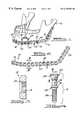
- FIG. 1is a perspective view of a mandibular osteosynthesis system constructed in accordance with the teachings of the preferred embodiment of the present invention illustrated in operative association with a human mandible.
- FIG. 2is an illustration the locking plate shown in FIG. 1 according to the teachings of the preferred embodiment of the present invention.
- FIG. 3is a cross-sectional view taken along the line 3 — 3 of FIG. 2 .
- FIG. 4is an exploded view of one of the fasteners shown in FIG. 1 according to the teachings of the preferred embodiment of the present invention.
- FIG. 5is a cross-sectional view taken along the line 5 — 5 of FIG. 4 .
- FIG. 6illustrates an end view of the head of the fastener shown in FIG. 4 according to the teachings of the preferred embodiment of the present invention.
- FIG. 7is a view of the auxiliary reinforcement member of FIG. 1 .
- FIG. 8is an enlarged cross-sectional view taken along the lines 8 — 8 of FIG. 7 .
- FIG. 9is an illustration of a pair of links in accordance with the teachings of the present invention.
- FIG. 10is a fragmentary exploded view of the pair of links of FIG. 9 and a cooperating anchor member.
- FIG. 11is a perspective view similar to FIG. 1, illustrating an alternative locking plate and an alternative auxiliary reinforcement member of the mandibular osteosynthesis system of the present invention operatively associated with a human mandible.
- FIG. 12is a cross-sectional view taken along the line 12 — 12 of FIG. 11 .
- FIG. 13is an illustration of a tool of the andibular osteosynthesis system of the present invention.
- FIG. 14is an enlarged view illustrating the detail shown in circle 14 identified in FIG. 13 .
- FIG. 15is an enlarged end view of the tool taken in the direction of arrow 15 shown in FIG. 14 .
- FIG. 16is a perspective view similar to FIG. 1, shown incorporating a mesh reinforcing member of the mandibular osteosynthesis system of the present invention.
- FIG. 17is an enlarged side view of the mesh reinforcing member of FIG. 16 .
- FIG. 18is a front view of an alternative mesh reinforcing member.
- a system constructed in accordance with a preferred embodiment of the present inventionis generally identified with reference numeral 10 .
- the system 10is shown operatively associated with a human mandibular 12 .
- a human mandibular 12a system constructed in accordance with a preferred embodiment of the present invention.
- the system 10 of the present inventionis shown to include an elongated reconstruction plate 14 .
- the plate 14is formed to include a plurality of apertures 16 , each adapted to receive a fastener 18 for interconnecting the plate 14 with the mandible 12 .
- the aperturespreferably include an oval countersink 20 and are internally threaded. For this reason, the plate 14 will be interchangeably referred to herein as a locking plate 14 .
- the locking plate 14is shown to generally include a central portion 22 , and first and second ends 24 and 26 .
- the first end 24is precontoured in an anterior-posterior direction to cooperate with the shape of the mandible 12 .
- the second end 24is also curved upwardly in the plane of the central portion 22 , this curvature of the second end 26 cooperates with the contour of the human mandible 12 when the locking plate 14 follows the shape of the mandible 12 in a medial-lateral direction.
- the locking plate 14is constructed of titanium. More preferably, the locking plate 14 is constructed from commercially pure, grade 2 or grade 4 titanium. However, it will be appreciated by those skilled in the art that other materials having suitable performance characteristics may be employed. Preferably, the locking plate 14 is inelastically deformable so as to retain its shape once contoured to cooperate with the shape of the mandible 12 .
- the fastener 18 of the present inventionis shown to generally include a main body 30 and a head member 32 .
- the main body 30includes an upper shaft portion 34 and a lower shaft portion 36 .
- the lower shaft portion 36is externally threaded and adapted to engage the mandible or bone 12 in a conventional manner. Insertion of the lower shaft portion into the bone is limited by a flange 38 interdisposed between the upper and lower shaft portions 34 and 36 .
- the upper shaft portion 32is also externally threaded and adapted to engage an internally threaded aperture 40 of the head member 32 .
- the head member 32is externally threaded for engaging one of the plurality of internally threaded apertures 16 of the locking plate 14 .
- the thread pitches of the upper shaft portion 34 , lower shaft portion 36 and the thread pitch of the external threads of the head member 32are common.
- the external threads of the head member 32 and the externally threaded lower shaft portion 36have a common thread lead.
- the externally threaded lower shaft portion 36has a single lead configuration while the external threads of the upper shaft portion 34 and head member 32 have a double lead configuration.
- a malleable template(not shown) is position on the mandible 12 and bent to the general shape of the cooperating bone surface.
- the locking plate 14is bent to approximately the shape of the template and positioned on the mandible 12 so that certain apertures 16 may be selectively used as a guide for drilling holes (not specifically shown) in the mandible 12 for receiving the fasteners 18 .
- a first of the fasteners 18is passed through a selected one of the apertures 16 and rotated so that the externally threaded lower portion 36 is driven into the hole in the mandible 12 .
- the first end 24 of the locking plate 14may be first secured to the mandible 12 with a first fastener 18 .
- Additional fasteners 18are used to interconnect the locking plate 14 with the bone 12 in a substantially identical manner. As shown in FIG. 1, four (4) fasteners are used to interconnect the locking plate 14 with the bone 12 . However, it will be appreciated by those skilled in the art that any number of fasteners 18 may be employed depending on a particular application. In one application, the order of the fastener insertion linearly progresses along the locking plate 14 from one end (e.g. the first end 24 ) to the second end (e.g. the second end 26 ). As additional fasteners are engaged with the bone 12 , the locking plate 14 is drawn into its operative position adjacent to the bone 12 .
- the head members 32 of each of the threaded fasteners 18are unthreaded from their respective upper portions 34 .
- Thisallows the surgeon to displace the locking plate 14 from the fasteners 18 and provides access to the bone 12 for accomplishing a desired surgical procedure (e. g., removal of a cancerous growth).
- a desired surgical proceduree. g., removal of a cancerous growth.
- the locking plate 14retains its shape due to go the inelastic deformation.
- the locking plate 14is replaced by inserting the upper portions 34 of the fasteners 18 through the selective apertures 14 and simultaneously threading the internal threads of the aperture 16 with the external threads of the upper portion 34 and the external threads of the head member 32 with the internal threads of the aperture 16 . Since the fasteners 18 are not removed from the bone 12 after initial insertion, fastener/bone purchase is not compromised.
- the toolincludes a handle 42 having an upper portion 44 and a lower portion 46 .
- the upper and lower portions 44 and 46are rotatable relative to one another about a longitudinal axis of the tool 40 .
- the upper portion 44is adapted to rotate with a first drive portion 48
- the lower portion 46 of the handle 42is adapted to rotate with a second drive portion SO.
- the first drive portion 48includes a generally rectangular tip 52 adapted to engage a generally rectangular aperture 54 provided in a top surface 56 of the upper shaft portion 34 of each fastener 18 .
- the second drive portion 50is illustrated to include four (4) drive elements equally spaced about the first drive member 48 .
- the drive elements 58are adapted to engage a corresponding number of slots 60 equally spaced about the head member 32 of each fastener 18 .
- the surgeonselects a fastener with the head portion 32 threaded onto the upper shaft portion 34 of the main body 30 and engages the drive elements 58 of the tool 40 with the slots 60 of the head member 32 simultaneously. Simultaneously, the tip 52 of the drive member 48 engages the rectangular aperture 54 of the upper shaft portion 34 .
- the surgeongrasps the upper and lower portions 44 and 49 of t ⁇ he handle 42 and rotates the tool 40 in a conventional manner. This action causes the head member 32 to threadably engage an aperture 16 of locking plate 14 and simultaneously causes the threads of the lower shaft portion 36 of the fastener 18 to engage the hole provided in the bone 12 .
- the surgeonagain engages the head 32 with the drive elements 58 .
- the thumb and forefingerare used to rotate the lower portion 46 of the handle 42 and in turn the rotate the head portion 32 of the fastener 18 in a counterclockwise direction.
- the palm and remaining fingersgrasp the upper portion 44 of the handle 42 so that the lower portion 46 can be rotated relative thereto.
- This actionremoves the head member 32 from its aperture 16 .
- the head portion 32is simultaneously unthreaded therefrom.
- the head portion 32is returned to threaded engagement with both the aperture 16 of the plate 14 and the upper shaft portion 32 of the main body portion 30 after the desired surgical procedure is performed on the mandible 12 .
- the locking plate 14When the locking plate 14 is operatively associated with the mandible 12 as shown in FIG. 1, the locking plate 14 is adjacent to but slightly displaced from the bone 12 .
- the flange 38which is interdisposed between the upper and lower externally threaded portions 34 and 36 of the fasteners 18 limits downward translation of the removable head member 32 .
- the thickness of the head member 32is greater than the thickness of the locking plate 14 .
- FIG. 1shows the auxiliary reinforcement member 64 operatively interconnecting a portion of the mandible 12 and the locking plate 14 .
- the auxiliary reinforcement member 64is intended to reinforce fractured or otherwise weakened portions of the bone 12 .
- the auxiliary reinforcement member 64is shown to generally include a bone attachment portion 66 and a pair of plate attachment portions 68 .
- the plate attachment portions 68are each interconnected to the bone attachment portion 66 through a leg portion 70 .
- the bone attachment portion 66is generally arcuate in shape and includes a plurality of apertures 72 .
- Each of the apertures 72includes a countersunk portion 74 .
- the apertures 72are each adapted to receive a threaded fastener 76 .
- the threaded fastener 76includes a head 78 adapted to seat in the countersunk portion 74 of the aperture 72 and a threaded shaft (not shown) for engaging a portion of the mandible 12 .
- the head 78 of the threaded fastener 76further includes a generally rectangular aperture substantially identical to the aperture 54 of the threaded fastener 18 . As such, the threaded fastener 76 may be inserted and removed with the first drive portion 48 of the tool 40 . Alternatively, a separate tool may be used to drive the fastener 76 .
- the plate engagement portions 68 of the auxiliary reinforcement member 64are generally circular in shape and include an aperture 80 having a countersunk portion 82 . As shown in FIG. 1, each of the plate engaging portions 68 may be interconnected to the plate 14 with a head portion 32 of the fastener 18 .
- a tapered flange portion 84 (shown in FIG. 4) of the removable head 32seats in the countersink 74 of the aperture 72 thereby securing the auxiliary reinforcement member 64 to the plate 14 when the external threads of the removable head 32 are engaged with the internal threads of one of the plate apertures 16 .
- each of the legs 70are connected to its associated plate engagement portion 68 through an intermediate portion 85 .
- the intermediate portion 85extends perpendicular to the plane of the bone engagement portion 66 and the plane of the plate engagement portion 68 .
- the plate engagement portion 66is stepped down from bone engagement portion 68 .
- the link system 88constructed in accordance with the teachings of the present invention is illustrated.
- the link system 88is intended to function as an alternative structure for the locking plate 14 and generally includes first and second links 90 and 92 which are preferably shown to be substantially linear in shape.
- Each of the links 90 and 92includes a plurality of apertures 16 substantially identical to the apertures 16 of the locking plate 14 .
- the apertures 16 of the first and second links 90 and 92are internally threaded and function with one or more fasteners 18 as discussed above. It will be understood by those skilled in the art that either of the first and second links 90 and 92 may have a non-linear shape.
- the first and second links 90 and 92are preferably shown to include cooperating ends 94 and 96 , respectively.
- the cooperating ends 94 and 96 of the first and second links 90 and 92are each provided with serrations 98 which circumferentially surround an aperture 100 .
- the apertures 100 surrounded by the serrations 98are not internally threaded.
- the first and second links 90 and 92are secured to one another and in turn to the bone 12 by a fastener 18 ′.
- the fastener 18 ′is largely identical to the fastener 18 described in connection with FIGS 4 - 6 . As such, identical reference numerals will be used to identify equivalent elements.
- the fastener 18 ′differs from the fastener 18 in that the external diameter of the head 32 is smooth, thereby permitting the first and second link members 90 and 92 to rotate relative to the fastener 18 ′, effectively defining a pivot.
- the second link 92 of the link system 88is shown to include a longitudinally extending groove 102 .
- the groove 102intersects the apertures 16 of the link 92 and functions to increase bending strength of the link 92 . It will be understood by those skilled in the art that a similar groove may be added to the first link 90 and also incorporated into the locking plate 14 of FIGS. 1 and 2.
- the fasteners 18 and 18 ′are constructed from 6AL4V titanium (ti64).
- 6AL4V titaniumti64
- other materials of having suitable strength and biocompatable characteristicsmay be incorporated.
- FIGS. 11 and 12a link reinforcement member 104 of the system 10 of the present invention is illustrated.
- FIG. 11illustrates the link reinforcement a member 104 operatively interconnected to a locking plate 14 to which is substantially identical to that described above with respect to FIGS. 1 and 2.
- the locking plate 14is in turn secured to the mandible 12 .
- FIG. 12is a cross-sectional view illustrating the cooperating relationship between the locking plate reinforcement member 104 and the locking plate 14 .
- the link reinforcement member 104is intended to reinforce the locking plate 14 at areas where significant bone mass may be absence.
- the reinforcement member 104is illustrated to include a plurality of apertures 106 adapted to align with apertures 16 of the locking plate 14 . As shown most clearly in FIG. 12, the locking plate reinforcement member 104 defines a groove 108 adapted to receive the locking plate 14 . In use, the plate reinforcement member 104 is placed over the locking plate 14 such that the locking plate 14 is positioned within the groove 108 and the apertures 106 are aligned with the apertures 16 . To secure the reinforcement member 104 to the plate 14 , a head portion 32 of the fastener 18 is used in a manner substantially identical to the interconnection of the auxiliary reinforcement plate 64 and the locking plate 14 .
- the tapered portion 84 of the removal head 32seats in a countersink portion 108 of the aperture 106 and the removable head 32 threadably engages an aligning aperture 16 of the locking plate 14 .
- a main body portion 30 of the fastener 18may also be employed for purposes of providing an additional point of attachment to the mandible 12 .
- FIGS. 16 and 17a mesh reinforcement member 110 of the system 10 of the present invention is illustrated.
- FIG. 16illustrates the mesh reinforcement member llo operatively interconnected to a reconstruction plate 14 which is substantially identical to that described above with respect to FIGS. 1 and 2.
- the plate 14is in turn secured to the mandible 12 .
- FIG. 17is an enlarged side view illustrating of the mesh reinforcement member 110 .
- the mesh reinforcement member 110provides another manner for reinforcement at areas of the mandible 12 where a resection has been made or significant bone mass is otherwise absent.
- the reconstruction plateis a locking plate 14 .
- the mesh reinforcement member 110may alternatively be used with a non-locking plate (not specifically shown).
- the mesh reinforcement member 110is constructed from a flexible, memory-retaining material such as titanium. In other applications, it may be desirable to construct the mesh reinforcement member 110 from a reoorbdble material.
- a reoorbdble materialincludes LactoSorb®, which is commercially available from W. Lorenz Surgical, Inc. of Jacksonville, Fla. LactoSorb® is a registered trademark of Biomet, Inc. of Warsaw, In. It will be readily appreciated that still other biocompatable materials may be used within the scope of the present invention.
- the mesh reinforcement member 110 of the present inventionis illustrated to include a repeating pattern having arger holes 112 aligned in rows and columns.
- the repeating patternadditionally includes smaller holes 114 similarly aligned in rows and columns.
- the smaller holes 114are arranged such that each smaller hole 114 is positioned equally between four larger holes 112 for the repeating pattern.
- the holes 112 and 114may be of smaller or larger size.
- the smaller holes 114are spaced so as to align with apertures 16 of the plate 14 .
- the mesh reinforcing member 110is provided in a generally U-shaped curved configuration.
- the mesh reinforcing member 110is adjusted to the general shape of the cooperating bone surface.
- a lower portion of the mesh reinforcing member 110wraps around a lower edge of the mandible 12 .
- the adjusted configuration of the mesh reinforcement member 110is shown in side view in FIG. 17 .
- desired surgical proceduresare made to the bone 12 and the mesh reinforcement member 110 is subsequently adjusted to the particular desired configuration.
- the mesh reinforcement member 110may be secured to the plate 14 and in turn secured to the mandible 12 by the fasteners 18 which otherwise secure the plate 14 to the mandible 12 .
- the mesh reinforcement member 110can be secured to the plate 14 and the plate 14 can be independently secured to the bone 12 , or the mesh reinforcement member can be independently secured to the bone 12 and subsequently secured to the plate 14 .
- FIG. 16illustrates a pair of fasteners 18 securing the mesh reinforcing member 110 to the plate 14 .
- the fasteners 18are shown to extend through one of the smaller holes 114 in the mesh reinforcing member 110 .
- additional fastenersmay be used to further secure the mesh reinforcing member 110 to the mandible.
- Such additional fastenersmay pass through other of the apertures 16 in the plate 14 , or directly through one of the smaller holes 114 or larger holes 112 of the mesh reinforcing member 110 .
- a variety of screwscan be used to secure the plate 14 , including but not limited to reconstruction screws, standard fracture screws, or dedicated screws.
- an alternative mesh reinforcing member 120is illustrated.
- the mesh reinforcement member 120is milled from titanium or other suitable material.
- a substantially identical mesh materialis commercially available from W. Lorenz Surgical, Inc. of Jacksonville, Fla. for cranial mesh applications.
- the alternative mesh reinforcement member 120has a repeating pattern including a plurality of smaller holes 122 joined by a webbing 124 .
- the alternative mesh reinforcement member 120may be more easily bent and configured to a desired contour. In certain applications, it may be desirable to incorporate larger holes into the alternative mesh reinforcement member 120 to a accommodate standard screws for attachment to the bone.
- the configuration of the plate 14 shown in the drawingsis one example of a plate suitable for use with the teachings of the present invention. It will be understood by those skilled in the art that various other shapes may be employed.
- the plate 14may be straight, angled, curved or any combination thereof. In certain applications, the plate 14 may extend about the entire mandible 12 .
Landscapes
- Health & Medical Sciences (AREA)
- Orthopedic Medicine & Surgery (AREA)
- Surgery (AREA)
- Life Sciences & Earth Sciences (AREA)
- Heart & Thoracic Surgery (AREA)
- Nuclear Medicine, Radiotherapy & Molecular Imaging (AREA)
- Engineering & Computer Science (AREA)
- Biomedical Technology (AREA)
- Medical Informatics (AREA)
- Molecular Biology (AREA)
- Animal Behavior & Ethology (AREA)
- General Health & Medical Sciences (AREA)
- Public Health (AREA)
- Veterinary Medicine (AREA)
- Neurology (AREA)
- Surgical Instruments (AREA)
- Prostheses (AREA)
Abstract
Description
Claims (13)
Priority Applications (3)
| Application Number | Priority Date | Filing Date | Title |
|---|---|---|---|
| US09/394,287US6325803B1 (en) | 1998-02-18 | 1999-09-10 | Method and apparatus for mandibular osteosynthesis |
| US10/047,520US20020062127A1 (en) | 1998-02-18 | 2001-10-29 | Method and apparatus for mandibular osteosynthesis |
| US10/081,166US7052499B2 (en) | 1998-02-18 | 2002-02-22 | Method and apparatus for bone fracture fixation |
Applications Claiming Priority (2)
| Application Number | Priority Date | Filing Date | Title |
|---|---|---|---|
| US09/025,140US6129728A (en) | 1998-02-18 | 1998-02-18 | Method and apparatus for mandibular osteosynthesis |
| US09/394,287US6325803B1 (en) | 1998-02-18 | 1999-09-10 | Method and apparatus for mandibular osteosynthesis |
Related Parent Applications (1)
| Application Number | Title | Priority Date | Filing Date |
|---|---|---|---|
| US09/025,140Continuation-In-PartUS6129728A (en) | 1998-02-18 | 1998-02-18 | Method and apparatus for mandibular osteosynthesis |
Related Child Applications (1)
| Application Number | Title | Priority Date | Filing Date |
|---|---|---|---|
| US10/047,520ContinuationUS20020062127A1 (en) | 1998-02-18 | 2001-10-29 | Method and apparatus for mandibular osteosynthesis |
Publications (1)
| Publication Number | Publication Date |
|---|---|
| US6325803B1true US6325803B1 (en) | 2001-12-04 |
Family
ID=26699345
Family Applications (2)
| Application Number | Title | Priority Date | Filing Date |
|---|---|---|---|
| US09/394,287Expired - LifetimeUS6325803B1 (en) | 1998-02-18 | 1999-09-10 | Method and apparatus for mandibular osteosynthesis |
| US10/047,520AbandonedUS20020062127A1 (en) | 1998-02-18 | 2001-10-29 | Method and apparatus for mandibular osteosynthesis |
Family Applications After (1)
| Application Number | Title | Priority Date | Filing Date |
|---|---|---|---|
| US10/047,520AbandonedUS20020062127A1 (en) | 1998-02-18 | 2001-10-29 | Method and apparatus for mandibular osteosynthesis |
Country Status (1)
| Country | Link |
|---|---|
| US (2) | US6325803B1 (en) |
Cited By (101)
| Publication number | Priority date | Publication date | Assignee | Title |
|---|---|---|---|---|
| USD469532S1 (en) | 2002-01-17 | 2003-01-28 | Zimmer, Inc. | Bone plate |
| US20030114857A1 (en)* | 2001-12-15 | 2003-06-19 | Carchidi Joseph Edward | Maxillofacial anchoring system for alveolar and small bone skeletal distraction |
| US20030208204A1 (en)* | 2001-04-17 | 2003-11-06 | Bailey Kirk J. | Anterior cervical plating system |
| US6699249B2 (en)* | 1999-05-14 | 2004-03-02 | Synthes (U.S.A.) | Bone fixation device with a rotation joint |
| US6730091B1 (en)* | 1999-05-03 | 2004-05-04 | Medartis Ag | Blockable bone plate |
| WO2004045389A2 (en) | 2002-11-19 | 2004-06-03 | Acumed Llc | Adjustable bone plates |
| US20040260291A1 (en)* | 2003-06-20 | 2004-12-23 | Jensen David G. | Bone plates with intraoperatively tapped apertures |
| US6869432B2 (en) | 2000-04-19 | 2005-03-22 | Synthes (U.S.A.) | Device for the articulated connection of two bodies |
| US20050130092A1 (en)* | 2002-01-23 | 2005-06-16 | Roger Minoretti | Distracting device for orthodontic/orosurgical purposes on the lower jaw |
| US6978188B1 (en)* | 2002-09-30 | 2005-12-20 | Medical Modeling, Llc | Method for contouring bone reconstruction plates |
| US20050288790A1 (en)* | 2003-04-16 | 2005-12-29 | Porex Surgical, Inc | Craniofacial implant |
| US20060149250A1 (en)* | 2004-12-14 | 2006-07-06 | Castaneda Javier E | Bone plate with pre-assembled drill guide tips |
| US20060161158A1 (en)* | 2004-12-14 | 2006-07-20 | Orbay Jorge L | Bone fracture fixation plate shaping system |
| US20060224242A1 (en)* | 2003-04-16 | 2006-10-05 | Porex Surgical, Inc. | Craniofacial implant |
| DE102005032026B3 (en)* | 2005-07-08 | 2006-12-14 | Stryker Leibinger Gmbh & Co. Kg | Osteosynthesis plate for treatment of mandibular fractures, has passage openings with angle adjustments with respect to one of longitudinal axes within plane, where adjustments deviate from each other at preset value with respect to axis |
| US7153309B2 (en) | 2002-11-19 | 2006-12-26 | Acumed Llc | Guide system for bone-repair devices |
| US7189237B2 (en) | 2002-11-19 | 2007-03-13 | Acumed Llc | Deformable bone plates |
| US7229445B2 (en) | 2004-06-21 | 2007-06-12 | Synthes (Usa) | Bone plate with bladed portion |
| US20070156147A1 (en)* | 2001-11-09 | 2007-07-05 | Robert Wang | Bone fixation device and method |
| US20070173844A1 (en)* | 2006-01-17 | 2007-07-26 | Ralph James D | Craniotomy closures and plugs |
| US20070233112A1 (en)* | 2006-03-20 | 2007-10-04 | Orbay Jorge L | Method of Bone Plate Shaping |
| US20070233109A1 (en)* | 2006-03-14 | 2007-10-04 | Synthes (Usa) | Condylar head add-on system |
| US20080161861A1 (en)* | 2006-10-17 | 2008-07-03 | Acumed Llc | Bone fixation with a strut-stabilized bone plate |
| US20080234766A1 (en)* | 2007-01-29 | 2008-09-25 | Polaris Biotechnology, Inc. | Craniospinal fusion method and apparatus |
| US20080281327A1 (en)* | 2007-05-07 | 2008-11-13 | Stryker Trauma | Sliding plate with reinforced slot |
| US20090018584A1 (en)* | 2007-01-29 | 2009-01-15 | Polaris Biotechnology, Inc. | Vertebra attachment method and system |
| US20090036894A1 (en)* | 2007-01-29 | 2009-02-05 | Polaris Biotechnology, Inc. | Method of treating a neurological condition through correction and stabilization of the clivo-axial angle |
| US20090076617A1 (en)* | 2006-01-17 | 2009-03-19 | Ralph James D | Craniotomy Closures |
| US7537603B2 (en) | 2002-07-22 | 2009-05-26 | Acumed Llc | Bone fusion system |
| US7537604B2 (en) | 2002-11-19 | 2009-05-26 | Acumed Llc | Bone plates with slots |
| US20090177230A1 (en)* | 2008-01-08 | 2009-07-09 | Polaris Biotechnology, Inc. | Osteointegration apparatus |
| US7578825B2 (en) | 2004-04-19 | 2009-08-25 | Acumed Llc | Placement of fasteners into bone |
| US20090259263A1 (en)* | 2008-04-11 | 2009-10-15 | Biomet Microfixation, Inc. | Apparatus and methods of fixating bone |
| US7635365B2 (en) | 2003-08-28 | 2009-12-22 | Ellis Thomas J | Bone plates |
| US7717945B2 (en) | 2002-07-22 | 2010-05-18 | Acumed Llc | Orthopedic systems |
| US20100130628A1 (en)* | 2007-03-29 | 2010-05-27 | Ube Industries, Ltd. | Aromatic polyimide and process for production thereof |
| US20100152575A1 (en)* | 2008-01-08 | 2010-06-17 | Polaris Biotechnology, Inc. | Mathematical Relationship of Strain, Neurological Dysfunction and Abnormal Behavior Resulting from Neurological Dysfunction of the Brainstem |
| US20100179552A1 (en)* | 2006-12-22 | 2010-07-15 | Dietmar Wolter | Repositioning and fixation system for bone fragments |
| US20100179597A1 (en)* | 2007-01-29 | 2010-07-15 | Polaris Biotechnology, Inc. | Craniospinal fusion method and apparatus |
| US20100179600A1 (en)* | 2002-02-22 | 2010-07-15 | Steger Shon D | Method and apparatus for bone fracture fixation |
| US7935126B2 (en) | 2006-03-20 | 2011-05-03 | Depuy Products, Inc. | Bone plate shaping system |
| US7951176B2 (en) | 2003-05-30 | 2011-05-31 | Synthes Usa, Llc | Bone plate |
| US20110218533A1 (en)* | 2010-03-08 | 2011-09-08 | Bernard Prandi | Radius-plate assembly |
| US20110218534A1 (en)* | 2010-03-08 | 2011-09-08 | Bernard Prandi | Adjustable-angle radius plate |
| US8177819B2 (en) | 2004-04-22 | 2012-05-15 | Acumed Llc | Expanded fixation of bones |
| US8568417B2 (en) | 2009-12-18 | 2013-10-29 | Charles River Engineering Solutions And Technologies, Llc | Articulating tool and methods of using |
| ITAN20120048A1 (en)* | 2012-05-02 | 2013-11-03 | Cizeta Surgical Societa A Responsa Bilita Limita | SCREW FOR PLANTS FOR BONE SURGERY. |
| US20130304075A1 (en)* | 2012-05-11 | 2013-11-14 | National Central University | Measuring and guiding device for reconstruction surgery |
| US20140141387A1 (en)* | 2011-05-25 | 2014-05-22 | Hitachi Metals, Ltd. | Keeper for implant and its assembly, and keeper-fixing method |
| US20140309638A1 (en)* | 2009-02-17 | 2014-10-16 | Obl | Customized osteosynthesis assembly |
| US9044195B2 (en) | 2013-05-02 | 2015-06-02 | University Of South Florida | Implantable sonic windows |
| US9237910B2 (en) | 2012-01-26 | 2016-01-19 | Acute Innovations Llc | Clip for rib stabilization |
| US9271765B2 (en) | 2011-02-24 | 2016-03-01 | Spinal Elements, Inc. | Vertebral facet joint fusion implant and method for fusion |
| US9381048B2 (en) | 2011-08-31 | 2016-07-05 | DePuy Synthes Products, Inc. | Devices and methods for cervical lateral fixation |
| US9421044B2 (en) | 2013-03-14 | 2016-08-23 | Spinal Elements, Inc. | Apparatus for bone stabilization and distraction and methods of use |
| USD765854S1 (en) | 2011-10-26 | 2016-09-06 | Spinal Elements, Inc. | Interbody bone implant |
| USD765843S1 (en)* | 2013-11-11 | 2016-09-06 | Kelyniam Global, Inc. | Mounting tab for a cranial implant |
| USD765853S1 (en)* | 2013-03-14 | 2016-09-06 | Spinal Elements, Inc. | Flexible elongate member with a portion configured to receive a bone anchor |
| US9456855B2 (en) | 2013-09-27 | 2016-10-04 | Spinal Elements, Inc. | Method of placing an implant between bone portions |
| US9517077B2 (en) | 2007-02-22 | 2016-12-13 | Spinal Elements, Inc. | Vertebral facet joint drill and method of use |
| USD777921S1 (en) | 2011-02-24 | 2017-01-31 | Spinal Elements, Inc. | Interbody bone implant |
| US9675387B2 (en) | 2004-02-06 | 2017-06-13 | Spinal Elements, Inc. | Vertebral facet joint prosthesis and method of fixation |
| US9743937B2 (en) | 2007-02-22 | 2017-08-29 | Spinal Elements, Inc. | Vertebral facet joint drill and method of use |
| EP2952145B1 (en) | 2010-04-29 | 2017-09-20 | Synthes GmbH | Orthognathic implant |
| US9775657B2 (en) | 2011-09-30 | 2017-10-03 | Acute Innovations Llc | Bone fixation system with opposed mounting portions |
| US9808294B2 (en) | 2011-02-24 | 2017-11-07 | Spinal Elements, Inc. | Methods and apparatus for stabilizing bone |
| US9820784B2 (en) | 2013-03-14 | 2017-11-21 | Spinal Elements, Inc. | Apparatus for spinal fixation and methods of use |
| US9827023B2 (en) | 2007-01-29 | 2017-11-28 | Life Spine, Inc. | Craniospinal fusion method and apparatus |
| US9839450B2 (en) | 2013-09-27 | 2017-12-12 | Spinal Elements, Inc. | Device and method for reinforcement of a facet |
| US9931142B2 (en) | 2004-06-10 | 2018-04-03 | Spinal Elements, Inc. | Implant and method for facet immobilization |
| US9956015B2 (en) | 2014-07-03 | 2018-05-01 | Acumed Llc | Bone plate with movable joint |
| US20190000628A1 (en)* | 2011-02-28 | 2019-01-03 | DePuy Synthes Products, Inc. | Modular tissue scaffolds |
| CN109620380A (en)* | 2019-01-21 | 2019-04-16 | 四川大学 | A kind of mandibular buccula porose area reduction of the fracture resting guide |
| US10335211B2 (en) | 2004-01-26 | 2019-07-02 | DePuy Synthes Products, Inc. | Highly-versatile variable-angle bone plate system |
| US10342586B2 (en) | 2003-08-26 | 2019-07-09 | DePuy Synthes Products, Inc. | Bone plate |
| US10470806B2 (en)* | 2017-02-07 | 2019-11-12 | Kls-Martin, L.P. | Maxillomandibular fixation devices |
| US10624686B2 (en) | 2016-09-08 | 2020-04-21 | DePuy Synthes Products, Inc. | Variable angel bone plate |
| US10758361B2 (en) | 2015-01-27 | 2020-09-01 | Spinal Elements, Inc. | Facet joint implant |
| US10772665B2 (en) | 2018-03-29 | 2020-09-15 | DePuy Synthes Products, Inc. | Locking structures for affixing bone anchors to a bone plate, and related systems and methods |
| US10820930B2 (en) | 2016-09-08 | 2020-11-03 | DePuy Synthes Products, Inc. | Variable angle bone plate |
| US10905476B2 (en) | 2016-09-08 | 2021-02-02 | DePuy Synthes Products, Inc. | Variable angle bone plate |
| US10925651B2 (en) | 2018-12-21 | 2021-02-23 | DePuy Synthes Products, Inc. | Implant having locking holes with collection cavity for shavings |
| US11013541B2 (en) | 2018-04-30 | 2021-05-25 | DePuy Synthes Products, Inc. | Threaded locking structures for affixing bone anchors to a bone plate, and related systems and methods |
| CN112914706A (en)* | 2021-03-17 | 2021-06-08 | 北京市富乐科技开发有限公司 | Acetabulum fracture reduction fixing system and use method |
| US11026727B2 (en) | 2018-03-20 | 2021-06-08 | DePuy Synthes Products, Inc. | Bone plate with form-fitting variable-angle locking hole |
| US11071571B2 (en)* | 2015-12-23 | 2021-07-27 | Karl Leibinger Medizintechnik Gmbh & Co. Kg | Implant for reinforcing a bone, comprising a bore vector specifying hole and surrounding plate for a jaw replacement, and implant production method |
| US11259851B2 (en) | 2003-08-26 | 2022-03-01 | DePuy Synthes Products, Inc. | Bone plate |
| US11291484B2 (en) | 2004-01-26 | 2022-04-05 | DePuy Synthes Products, Inc. | Highly-versatile variable-angle bone plate system |
| US11304733B2 (en) | 2020-02-14 | 2022-04-19 | Spinal Elements, Inc. | Bone tie methods |
| US11357514B2 (en) | 2010-04-29 | 2022-06-14 | DePuy Synthes Products, Inc. | Orthognathic implant and methods of use |
| DE102021104306A1 (en) | 2021-02-23 | 2022-08-25 | Universität Stuttgart Körperschaft des öffentlichen Rechts | osteosynthesis plate |
| DE102021104308A1 (en) | 2021-02-23 | 2022-08-25 | Universität Stuttgart (Körperschaft Des Öffentlichen Rechts) | osteosynthesis plate |
| US11457959B2 (en) | 2019-05-22 | 2022-10-04 | Spinal Elements, Inc. | Bone tie and bone tie inserter |
| US11457912B2 (en) | 2016-06-02 | 2022-10-04 | Parcus Medical, Llc | Suture tool and method of use |
| US11464552B2 (en) | 2019-05-22 | 2022-10-11 | Spinal Elements, Inc. | Bone tie and bone tie inserter |
| US11478275B2 (en) | 2014-09-17 | 2022-10-25 | Spinal Elements, Inc. | Flexible fastening band connector |
| RU2796861C1 (en)* | 2022-05-27 | 2023-05-29 | Джошгун Ядигар оглы Бабаев | Corrective apparatus for treating children with fractures of the condylar process of the lower jaw and a method for conservative treatment of children with fractures of the condylar process of the lower jaw |
| US11801125B2 (en)* | 2019-10-23 | 2023-10-31 | Industrial Technology Research Institute | Reconstruction prosthesis |
| US12089882B2 (en) | 2019-04-30 | 2024-09-17 | Fusion Innovations, Llc | Method and system for assembling a structure to secure to opposite sides of a fracture in a bone of a subject |
| US12285197B2 (en) | 2008-10-10 | 2025-04-29 | Acumed Llc | Bone fixation system with opposed mounting portions |
| US12369952B2 (en) | 2021-12-10 | 2025-07-29 | Spinal Elements, Inc. | Bone tie and portal |
Families Citing this family (29)
| Publication number | Priority date | Publication date | Assignee | Title |
|---|---|---|---|---|
| US20050090825A1 (en)* | 2002-02-15 | 2005-04-28 | Medartis Ag | Bone plate |
| EP1464295A3 (en)* | 2003-04-01 | 2006-04-26 | Zimmer GmbH | Implant |
| US7887587B2 (en)* | 2004-06-04 | 2011-02-15 | Synthes Usa, Llc | Soft tissue spacer |
| US20150335438A1 (en) | 2006-02-27 | 2015-11-26 | Biomet Manufacturing, Llc. | Patient-specific augments |
| US9289253B2 (en) | 2006-02-27 | 2016-03-22 | Biomet Manufacturing, Llc | Patient-specific shoulder guide |
| US9339278B2 (en) | 2006-02-27 | 2016-05-17 | Biomet Manufacturing, Llc | Patient-specific acetabular guides and associated instruments |
| US9907659B2 (en) | 2007-04-17 | 2018-03-06 | Biomet Manufacturing, Llc | Method and apparatus for manufacturing an implant |
| US9345548B2 (en) | 2006-02-27 | 2016-05-24 | Biomet Manufacturing, Llc | Patient-specific pre-operative planning |
| US9918740B2 (en) | 2006-02-27 | 2018-03-20 | Biomet Manufacturing, Llc | Backup surgical instrument system and method |
| US9173661B2 (en) | 2006-02-27 | 2015-11-03 | Biomet Manufacturing, Llc | Patient specific alignment guide with cutting surface and laser indicator |
| US8407067B2 (en) | 2007-04-17 | 2013-03-26 | Biomet Manufacturing Corp. | Method and apparatus for manufacturing an implant |
| US10278711B2 (en) | 2006-02-27 | 2019-05-07 | Biomet Manufacturing, Llc | Patient-specific femoral guide |
| US9795399B2 (en) | 2006-06-09 | 2017-10-24 | Biomet Manufacturing, Llc | Patient-specific knee alignment guide and associated method |
| CA2702952C (en) | 2007-10-27 | 2017-01-03 | Parcus Medical, Llc | Suture anchor |
| US8282674B2 (en)* | 2008-07-18 | 2012-10-09 | Suspension Orthopaedic Solutions, Inc. | Clavicle fixation |
| DE102008034300A1 (en)* | 2008-07-23 | 2010-01-28 | Lucas Automotive Gmbh | Vehicle disc brake |
| US9113970B2 (en)* | 2010-03-10 | 2015-08-25 | Orthohelix Surgical Designs, Inc. | System for achieving selectable fixation in an orthopedic plate |
| KR101137937B1 (en)* | 2010-05-07 | 2012-05-09 | 안장훈 | Dental screw and driver |
| US8518042B2 (en)* | 2010-10-19 | 2013-08-27 | Biomet Manufacturing, Llc | Orthopedic plate assembly for a distal radius having re-contouring features and method for using same |
| US9867638B2 (en)* | 2011-11-25 | 2018-01-16 | University Of Cape Town | Transport distraction apparatus |
| WO2015171962A1 (en) | 2014-05-07 | 2015-11-12 | Bart Bracy | Multipart suture |
| USD779065S1 (en) | 2014-10-08 | 2017-02-14 | Nuvasive, Inc. | Anterior cervical bone plate |
| CN104771231B (en)* | 2015-04-27 | 2016-10-12 | 四川大学 | Guider for orthognathic surgery bone piece displacement and preparation method thereof |
| US11517301B2 (en) | 2016-06-02 | 2022-12-06 | Parcus Medical, Llc | Surgical tool and method of use |
| BR112019015878A2 (en) | 2017-02-06 | 2020-04-14 | Depuy Synthes Products Inc | foldable graft containment cage |
| US10722310B2 (en) | 2017-03-13 | 2020-07-28 | Zimmer Biomet CMF and Thoracic, LLC | Virtual surgery planning system and method |
| US10932912B2 (en)* | 2017-09-11 | 2021-03-02 | DePuy Synthes Products, Inc. | Plug in struts for graft cage |
| CN113197641A (en)* | 2021-05-13 | 2021-08-03 | 河北医科大学第三医院 | Angle-adjustable bone fracture plate for distal femur |
| US12295849B2 (en)* | 2023-01-26 | 2025-05-13 | Jason D. Toranto | Mandibular reconstruction systems and methods |
Citations (37)
| Publication number | Priority date | Publication date | Assignee | Title |
|---|---|---|---|---|
| US1105105A (en) | 1912-02-10 | 1914-07-28 | William O'n Sherman | Surgical appliance. |
| US2489870A (en) | 1946-03-02 | 1949-11-29 | Dzus William | Bone fastening device |
| US2494229A (en) | 1946-07-08 | 1950-01-10 | John G Collison | Bone surgery |
| DE867422C (en)* | 1951-11-13 | 1953-02-16 | Alfred Dr Med Abel | Screw-on bone plate for the healing of broken bones |
| US2631584A (en) | 1948-07-22 | 1953-03-17 | Alfred T Purificato | Fracture securing instrument |
| US3488779A (en) | 1967-09-27 | 1970-01-13 | Robert W Christensen | Orthopedic prosthetic appliances for attachment to bone |
| US4219015A (en) | 1977-04-22 | 1980-08-26 | Institut Straumann Ag | Plates for osteosynthesis |
| US4429690A (en) | 1980-09-15 | 1984-02-07 | Cise Centro Informazioni Studi Esperienze Spa | Plate for broken bone fixation |
| US4484570A (en) | 1980-05-28 | 1984-11-27 | Synthes Ltd. | Device comprising an implant and screws for fastening said implant to a bone, and a device for connecting two separated pieces of bone |
| US4708132A (en) | 1986-01-24 | 1987-11-24 | Pfizer-Hospital Products Group, Inc. | Fixation device for a ligament or tendon prosthesis |
| US4903691A (en) | 1986-01-22 | 1990-02-27 | Thomas Heinl | Set of surgical instruments for joining bone fragments |
| US4959065A (en) | 1989-07-14 | 1990-09-25 | Techmedica, Inc. | Bone plate with positioning member |
| US4973332A (en) | 1988-09-12 | 1990-11-27 | Hospital For Joint Diseases | Attachment for femur sliding screw plate |
| US5108399A (en) | 1988-09-17 | 1992-04-28 | Boehringer Ingelheim Gmbh | Device for osteosynthesis and process for producing it |
| US5108395A (en) | 1989-09-18 | 1992-04-28 | Societe De Fabrication De Materiel Orthopedique - Sofamor | Implant for anterior dorsolumbar spinal osteosynthesis, intended for the correction of kyphoses |
| US5129899A (en) | 1991-03-27 | 1992-07-14 | Smith & Nephew Richards Inc. | Bone fixation apparatus |
| US5147363A (en) | 1989-12-21 | 1992-09-15 | Haerle Anton | Screw for use in osteosynthesis |
| US5151103A (en) | 1987-11-03 | 1992-09-29 | Synthes (U.S.A.) | Point contact bone compression plate |
| US5180382A (en) | 1990-12-19 | 1993-01-19 | Synthes (U.S.A.) | Bone screw |
| US5269784A (en) | 1991-12-10 | 1993-12-14 | Synthes (U.S.A.) | Screw nut for plate osteosynthesis |
| US5303718A (en) | 1990-12-29 | 1994-04-19 | Milan Krajicek | Method and device for the osteosynthesis of bones |
| US5358367A (en) | 1992-03-18 | 1994-10-25 | Yang Tai Her | Screw or nut packing micro-adjustment |
| US5372598A (en) | 1987-05-14 | 1994-12-13 | Howmedica Gmbh | Small bone plate for cranial or facial fractures or the like |
| US5403136A (en) | 1991-06-25 | 1995-04-04 | Synthes (U.S.A.) | Threaded fastener especially for orthopaedic purposes |
| US5413577A (en) | 1987-04-07 | 1995-05-09 | Pollock; Richard A. | Anatomical precontoured plating |
| US5474551A (en) | 1994-11-18 | 1995-12-12 | Smith & Nephew Richards, Inc. | Universal coupler for spinal fixation |
| US5505731A (en) | 1993-09-01 | 1996-04-09 | Tornier Sa | Screw for lumbar-sacral fixator |
| US5520690A (en) | 1995-04-13 | 1996-05-28 | Errico; Joseph P. | Anterior spinal polyaxial locking screw plate assembly |
| US5569247A (en) | 1995-03-27 | 1996-10-29 | Smith & Nephew Richards, Inc. | Enhanced variable angle bone bolt |
| US5591167A (en) | 1994-02-15 | 1997-01-07 | Sofamor, S.N.C. | Anterior dorso-lumbar spinal osteosynthesis instrumentation for the correction of kyphosis |
| US5601554A (en) | 1993-03-04 | 1997-02-11 | Advanced Spine Fixation Systems, Inc. | Branch connector for spinal fixation systems |
| US5601553A (en) | 1994-10-03 | 1997-02-11 | Synthes (U.S.A.) | Locking plate and bone screw |
| US5607428A (en) | 1995-05-01 | 1997-03-04 | Lin; Kwan C. | Orthopedic fixation device having a double-threaded screw |
| US5653710A (en) | 1993-11-23 | 1997-08-05 | Haerle; Anton | Osteosynthetic force transmitting member |
| US5676667A (en) | 1995-12-08 | 1997-10-14 | Hausman; Michael | Bone fixation apparatus and method |
| US5722976A (en)* | 1993-08-27 | 1998-03-03 | Brown; Robin Peter | Apparatus and method for surgically securing bone parts |
| US6007538A (en)* | 1997-07-25 | 1999-12-28 | Duke University | Sternal closure device |
Family Cites Families (3)
| Publication number | Priority date | Publication date | Assignee | Title |
|---|---|---|---|---|
| WO1995010238A1 (en)* | 1993-10-08 | 1995-04-20 | Chaim Rogozinski | Spinal treatment apparatus and method including multi-directional attachment member |
| CA2189744C (en)* | 1995-03-27 | 2003-09-16 | Gilbert Talos | Bone plate |
| US5707372A (en)* | 1996-07-11 | 1998-01-13 | Third Millennium Engineering, Llc. | Multiple node variable length cross-link device |
- 1999
- 1999-09-10USUS09/394,287patent/US6325803B1/ennot_activeExpired - Lifetime
- 2001
- 2001-10-29USUS10/047,520patent/US20020062127A1/ennot_activeAbandoned
Patent Citations (37)
| Publication number | Priority date | Publication date | Assignee | Title |
|---|---|---|---|---|
| US1105105A (en) | 1912-02-10 | 1914-07-28 | William O'n Sherman | Surgical appliance. |
| US2489870A (en) | 1946-03-02 | 1949-11-29 | Dzus William | Bone fastening device |
| US2494229A (en) | 1946-07-08 | 1950-01-10 | John G Collison | Bone surgery |
| US2631584A (en) | 1948-07-22 | 1953-03-17 | Alfred T Purificato | Fracture securing instrument |
| DE867422C (en)* | 1951-11-13 | 1953-02-16 | Alfred Dr Med Abel | Screw-on bone plate for the healing of broken bones |
| US3488779A (en) | 1967-09-27 | 1970-01-13 | Robert W Christensen | Orthopedic prosthetic appliances for attachment to bone |
| US4219015A (en) | 1977-04-22 | 1980-08-26 | Institut Straumann Ag | Plates for osteosynthesis |
| US4484570A (en) | 1980-05-28 | 1984-11-27 | Synthes Ltd. | Device comprising an implant and screws for fastening said implant to a bone, and a device for connecting two separated pieces of bone |
| US4429690A (en) | 1980-09-15 | 1984-02-07 | Cise Centro Informazioni Studi Esperienze Spa | Plate for broken bone fixation |
| US4903691A (en) | 1986-01-22 | 1990-02-27 | Thomas Heinl | Set of surgical instruments for joining bone fragments |
| US4708132A (en) | 1986-01-24 | 1987-11-24 | Pfizer-Hospital Products Group, Inc. | Fixation device for a ligament or tendon prosthesis |
| US5413577A (en) | 1987-04-07 | 1995-05-09 | Pollock; Richard A. | Anatomical precontoured plating |
| US5372598A (en) | 1987-05-14 | 1994-12-13 | Howmedica Gmbh | Small bone plate for cranial or facial fractures or the like |
| US5151103A (en) | 1987-11-03 | 1992-09-29 | Synthes (U.S.A.) | Point contact bone compression plate |
| US4973332A (en) | 1988-09-12 | 1990-11-27 | Hospital For Joint Diseases | Attachment for femur sliding screw plate |
| US5108399A (en) | 1988-09-17 | 1992-04-28 | Boehringer Ingelheim Gmbh | Device for osteosynthesis and process for producing it |
| US4959065A (en) | 1989-07-14 | 1990-09-25 | Techmedica, Inc. | Bone plate with positioning member |
| US5108395A (en) | 1989-09-18 | 1992-04-28 | Societe De Fabrication De Materiel Orthopedique - Sofamor | Implant for anterior dorsolumbar spinal osteosynthesis, intended for the correction of kyphoses |
| US5147363A (en) | 1989-12-21 | 1992-09-15 | Haerle Anton | Screw for use in osteosynthesis |
| US5180382A (en) | 1990-12-19 | 1993-01-19 | Synthes (U.S.A.) | Bone screw |
| US5303718A (en) | 1990-12-29 | 1994-04-19 | Milan Krajicek | Method and device for the osteosynthesis of bones |
| US5129899A (en) | 1991-03-27 | 1992-07-14 | Smith & Nephew Richards Inc. | Bone fixation apparatus |
| US5403136A (en) | 1991-06-25 | 1995-04-04 | Synthes (U.S.A.) | Threaded fastener especially for orthopaedic purposes |
| US5269784A (en) | 1991-12-10 | 1993-12-14 | Synthes (U.S.A.) | Screw nut for plate osteosynthesis |
| US5358367A (en) | 1992-03-18 | 1994-10-25 | Yang Tai Her | Screw or nut packing micro-adjustment |
| US5601554A (en) | 1993-03-04 | 1997-02-11 | Advanced Spine Fixation Systems, Inc. | Branch connector for spinal fixation systems |
| US5722976A (en)* | 1993-08-27 | 1998-03-03 | Brown; Robin Peter | Apparatus and method for surgically securing bone parts |
| US5505731A (en) | 1993-09-01 | 1996-04-09 | Tornier Sa | Screw for lumbar-sacral fixator |
| US5653710A (en) | 1993-11-23 | 1997-08-05 | Haerle; Anton | Osteosynthetic force transmitting member |
| US5591167A (en) | 1994-02-15 | 1997-01-07 | Sofamor, S.N.C. | Anterior dorso-lumbar spinal osteosynthesis instrumentation for the correction of kyphosis |
| US5601553A (en) | 1994-10-03 | 1997-02-11 | Synthes (U.S.A.) | Locking plate and bone screw |
| US5474551A (en) | 1994-11-18 | 1995-12-12 | Smith & Nephew Richards, Inc. | Universal coupler for spinal fixation |
| US5569247A (en) | 1995-03-27 | 1996-10-29 | Smith & Nephew Richards, Inc. | Enhanced variable angle bone bolt |
| US5520690A (en) | 1995-04-13 | 1996-05-28 | Errico; Joseph P. | Anterior spinal polyaxial locking screw plate assembly |
| US5607428A (en) | 1995-05-01 | 1997-03-04 | Lin; Kwan C. | Orthopedic fixation device having a double-threaded screw |
| US5676667A (en) | 1995-12-08 | 1997-10-14 | Hausman; Michael | Bone fixation apparatus and method |
| US6007538A (en)* | 1997-07-25 | 1999-12-28 | Duke University | Sternal closure device |
Cited By (210)
| Publication number | Priority date | Publication date | Assignee | Title |
|---|---|---|---|---|
| US6730091B1 (en)* | 1999-05-03 | 2004-05-04 | Medartis Ag | Blockable bone plate |
| US20040127903A1 (en)* | 1999-05-14 | 2004-07-01 | Synthes (Usa) | Bone fixation device with a rotation joint |
| US6699249B2 (en)* | 1999-05-14 | 2004-03-02 | Synthes (U.S.A.) | Bone fixation device with a rotation joint |
| US7201753B2 (en) | 1999-05-14 | 2007-04-10 | Synthes (U.S.A.) | Bone fixation device with a rotation joint |
| US6869432B2 (en) | 2000-04-19 | 2005-03-22 | Synthes (U.S.A.) | Device for the articulated connection of two bodies |
| US20030208204A1 (en)* | 2001-04-17 | 2003-11-06 | Bailey Kirk J. | Anterior cervical plating system |
| US20070156147A1 (en)* | 2001-11-09 | 2007-07-05 | Robert Wang | Bone fixation device and method |
| US20030114857A1 (en)* | 2001-12-15 | 2003-06-19 | Carchidi Joseph Edward | Maxillofacial anchoring system for alveolar and small bone skeletal distraction |
| US6887275B2 (en)* | 2001-12-15 | 2005-05-03 | Ace Surgical Supply Co., Inc. | Maxillofacial anchoring system for alveolar and small bone skeletal distraction |
| USD469532S1 (en) | 2002-01-17 | 2003-01-28 | Zimmer, Inc. | Bone plate |
| US7347687B2 (en)* | 2002-01-23 | 2008-03-25 | Roger Minoretti | Distraction apparatus for orthodontic, orthognathic and oral/maxillofacial surgery applications on the mandible |
| US20050130092A1 (en)* | 2002-01-23 | 2005-06-16 | Roger Minoretti | Distracting device for orthodontic/orosurgical purposes on the lower jaw |
| US20100179600A1 (en)* | 2002-02-22 | 2010-07-15 | Steger Shon D | Method and apparatus for bone fracture fixation |
| US8460345B2 (en) | 2002-02-22 | 2013-06-11 | Biomet Microfixation, Llc | Method and apparatus for bone fracture fixation |
| US7717945B2 (en) | 2002-07-22 | 2010-05-18 | Acumed Llc | Orthopedic systems |
| US9308033B2 (en) | 2002-07-22 | 2016-04-12 | Acumed Llc | Adjustable bone plates |
| US10456180B2 (en) | 2002-07-22 | 2019-10-29 | Acumed Llc | Adjustable bone plates |
| US7537603B2 (en) | 2002-07-22 | 2009-05-26 | Acumed Llc | Bone fusion system |
| US8425574B2 (en) | 2002-07-22 | 2013-04-23 | Acumed, Llc | Bone fixation with a bone plate attached to a fastener assembly |
| US6978188B1 (en)* | 2002-09-30 | 2005-12-20 | Medical Modeling, Llc | Method for contouring bone reconstruction plates |
| GB2412590A (en)* | 2002-11-19 | 2005-10-05 | Acumed Llc | Adjustable bone plates |
| US7326212B2 (en) | 2002-11-19 | 2008-02-05 | Acumed Llc | Bone plates with reference marks |
| US7189237B2 (en) | 2002-11-19 | 2007-03-13 | Acumed Llc | Deformable bone plates |
| WO2004045389A3 (en)* | 2002-11-19 | 2004-08-19 | Acumed Llc | Adjustable bone plates |
| US7704251B2 (en) | 2002-11-19 | 2010-04-27 | Acumed Llc | Adjustable bone plates |
| US7090676B2 (en) | 2002-11-19 | 2006-08-15 | Acumed Llc | Adjustable bone plates |
| WO2004045389A2 (en) | 2002-11-19 | 2004-06-03 | Acumed Llc | Adjustable bone plates |
| US7153309B2 (en) | 2002-11-19 | 2006-12-26 | Acumed Llc | Guide system for bone-repair devices |
| GB2412590B (en)* | 2002-11-19 | 2006-05-17 | Acumed Llc | Adjustable bone plates |
| US7537604B2 (en) | 2002-11-19 | 2009-05-26 | Acumed Llc | Bone plates with slots |
| EP1567071A4 (en)* | 2002-11-19 | 2010-04-28 | Acumed Llc | Adjustable bone plates |
| KR101081269B1 (en)* | 2002-11-19 | 2011-11-08 | 어큠드 엘엘씨 | Adjustable pattern plate |
| US7655047B2 (en) | 2003-04-16 | 2010-02-02 | Porex Surgical, Inc. | Craniofacial implant |
| US20050288790A1 (en)* | 2003-04-16 | 2005-12-29 | Porex Surgical, Inc | Craniofacial implant |
| US20100114316A1 (en)* | 2003-04-16 | 2010-05-06 | Porex Surgical, Inc. | Craniofacial Implant |
| US8298292B2 (en) | 2003-04-16 | 2012-10-30 | Howmedica Osteonics Corp. | Craniofacial implant |
| US8398720B2 (en) | 2003-04-16 | 2013-03-19 | Orthovita, Inc. | Craniofacial implant |
| US20060224242A1 (en)* | 2003-04-16 | 2006-10-05 | Porex Surgical, Inc. | Craniofacial implant |
| US9308034B2 (en) | 2003-05-30 | 2016-04-12 | DePuy Synthes Products, Inc. | Bone plate |
| US7951176B2 (en) | 2003-05-30 | 2011-05-31 | Synthes Usa, Llc | Bone plate |
| US10231768B2 (en) | 2003-05-30 | 2019-03-19 | DePuy Synthes Products, Inc. | Methods for implanting bone plates |
| US10653466B2 (en) | 2003-05-30 | 2020-05-19 | DePuy Synthes Products, Inc. | Bone plate |
| US9931148B2 (en) | 2003-05-30 | 2018-04-03 | DePuy Synthes Products, Inc. | Bone plate |
| US11419647B2 (en) | 2003-05-30 | 2022-08-23 | DePuy Synthes Products, Inc. | Bone plate |
| US20040260291A1 (en)* | 2003-06-20 | 2004-12-23 | Jensen David G. | Bone plates with intraoperatively tapped apertures |
| US7537596B2 (en) | 2003-06-20 | 2009-05-26 | Acumed Llc | Bone plates with intraoperatively tapped apertures |
| US10342586B2 (en) | 2003-08-26 | 2019-07-09 | DePuy Synthes Products, Inc. | Bone plate |
| US11259851B2 (en) | 2003-08-26 | 2022-03-01 | DePuy Synthes Products, Inc. | Bone plate |
| US7635365B2 (en) | 2003-08-28 | 2009-12-22 | Ellis Thomas J | Bone plates |
| US7695501B2 (en) | 2003-08-28 | 2010-04-13 | Ellis Thomas J | Bone fixation system |
| US8632573B2 (en) | 2003-08-28 | 2014-01-21 | Thomas J. Ellis | Bone fixation system |
| US10335211B2 (en) | 2004-01-26 | 2019-07-02 | DePuy Synthes Products, Inc. | Highly-versatile variable-angle bone plate system |
| US11291484B2 (en) | 2004-01-26 | 2022-04-05 | DePuy Synthes Products, Inc. | Highly-versatile variable-angle bone plate system |
| US10085776B2 (en) | 2004-02-06 | 2018-10-02 | Spinal Elements, Inc. | Vertebral facet joint prosthesis and method of fixation |
| US9675387B2 (en) | 2004-02-06 | 2017-06-13 | Spinal Elements, Inc. | Vertebral facet joint prosthesis and method of fixation |
| US7578825B2 (en) | 2004-04-19 | 2009-08-25 | Acumed Llc | Placement of fasteners into bone |
| US8177819B2 (en) | 2004-04-22 | 2012-05-15 | Acumed Llc | Expanded fixation of bones |
| US9931142B2 (en) | 2004-06-10 | 2018-04-03 | Spinal Elements, Inc. | Implant and method for facet immobilization |
| US7229445B2 (en) | 2004-06-21 | 2007-06-12 | Synthes (Usa) | Bone plate with bladed portion |
| US7771433B2 (en) | 2004-12-14 | 2010-08-10 | Depuy Products, Inc. | Bone fracture fixation plate shaping system |
| US20060149250A1 (en)* | 2004-12-14 | 2006-07-06 | Castaneda Javier E | Bone plate with pre-assembled drill guide tips |
| US20060161158A1 (en)* | 2004-12-14 | 2006-07-20 | Orbay Jorge L | Bone fracture fixation plate shaping system |
| US9220515B2 (en) | 2004-12-14 | 2015-12-29 | Biomet C.V. | Bone plate with pre-assembled drill guide tips |
| US9370376B2 (en) | 2004-12-14 | 2016-06-21 | Biomet C.V. | Drill guides and extension therefor for simultaneous use on a bone plate |
| US8545540B2 (en) | 2004-12-14 | 2013-10-01 | Biomet C.V. | Bone plate with pre-assembled drill guide tips |
| US8834537B2 (en) | 2004-12-14 | 2014-09-16 | Biomet C.V. | Drill guides for bone plate |
| US8241338B2 (en) | 2004-12-14 | 2012-08-14 | Biomet C.V. | Bone plate with pre-assembled drill guide tips |
| US8172886B2 (en) | 2004-12-14 | 2012-05-08 | Depuy Products, Inc. | Bone plate with pre-assembled drill guide tips |
| DE102005032026B3 (en)* | 2005-07-08 | 2006-12-14 | Stryker Leibinger Gmbh & Co. Kg | Osteosynthesis plate for treatment of mandibular fractures, has passage openings with angle adjustments with respect to one of longitudinal axes within plane, where adjustments deviate from each other at preset value with respect to axis |
| US8672981B2 (en) | 2005-07-08 | 2014-03-18 | Stryker Leibinger Gmbh & Co. Kg. | Osteosynthesis plate comprising through-openings which are inclined in relation to the plane of the plate |
| US20090318920A1 (en)* | 2005-07-08 | 2009-12-24 | Jacobs Fred J | Osteosynthesis Plate Comprising Through-Openings Which are Inclined in Relation to the Plane of the Plate |
| US8080042B2 (en) | 2006-01-17 | 2011-12-20 | Biodynamics, Llc | Craniotomy closures and plugs |
| US7833253B2 (en)* | 2006-01-17 | 2010-11-16 | Biodynamics Llc | Craniotomy closures and plugs |
| US8597335B2 (en) | 2006-01-17 | 2013-12-03 | Biodynamics Llc | Craniotomy closures and plugs |
| US20100179554A1 (en)* | 2006-01-17 | 2010-07-15 | Ralph James D | Craniotomy Closures and Plugs |
| US8083782B2 (en) | 2006-01-17 | 2011-12-27 | Biodynamics Llc | Craniotomy closures and plugs |
| US8460346B2 (en) | 2006-01-17 | 2013-06-11 | Biodynamics Llc | Craniotomy closures |
| US20070173844A1 (en)* | 2006-01-17 | 2007-07-26 | Ralph James D | Craniotomy closures and plugs |
| US20090076617A1 (en)* | 2006-01-17 | 2009-03-19 | Ralph James D | Craniotomy Closures |
| US9289241B2 (en) | 2006-01-17 | 2016-03-22 | Biodynamics Llc | Craniotomy closures |
| US20100179553A1 (en)* | 2006-01-17 | 2010-07-15 | Ralph James D | Craniotomy Closures and Plugs |
| US20070233109A1 (en)* | 2006-03-14 | 2007-10-04 | Synthes (Usa) | Condylar head add-on system |
| US7601175B2 (en) | 2006-03-14 | 2009-10-13 | Synthes Usa, Llc | Condylar head add-on system |
| US9615874B2 (en) | 2006-03-20 | 2017-04-11 | Biomet C.V. | Bone plate shaping system |
| US7935126B2 (en) | 2006-03-20 | 2011-05-03 | Depuy Products, Inc. | Bone plate shaping system |
| US8858562B2 (en) | 2006-03-20 | 2014-10-14 | Biomet C.V. | Bone plate shaping system |
| US7740634B2 (en) | 2006-03-20 | 2010-06-22 | Depuy Products, Inc. | Method of bone plate shaping |
| US20070233112A1 (en)* | 2006-03-20 | 2007-10-04 | Orbay Jorge L | Method of Bone Plate Shaping |
| US8231662B2 (en)* | 2006-10-17 | 2012-07-31 | Acumed Llc | Bone fixation with a strut-stabilized bone plate |
| US20080161861A1 (en)* | 2006-10-17 | 2008-07-03 | Acumed Llc | Bone fixation with a strut-stabilized bone plate |
| US20100179552A1 (en)* | 2006-12-22 | 2010-07-15 | Dietmar Wolter | Repositioning and fixation system for bone fragments |
| US8287542B2 (en)* | 2006-12-22 | 2012-10-16 | Dietmar Wolter | Repositioning and fixation system for bone fragments |
| US9107717B2 (en) | 2007-01-29 | 2015-08-18 | Life Spine, Inc. | Craniospinal fusion method and apparatus |
| US20090036894A1 (en)* | 2007-01-29 | 2009-02-05 | Polaris Biotechnology, Inc. | Method of treating a neurological condition through correction and stabilization of the clivo-axial angle |
| US9827023B2 (en) | 2007-01-29 | 2017-11-28 | Life Spine, Inc. | Craniospinal fusion method and apparatus |
| US8043342B2 (en) | 2007-01-29 | 2011-10-25 | Polaris Biotechnology, Inc. | Craniospinal fusion method and apparatus |
| US20100179597A1 (en)* | 2007-01-29 | 2010-07-15 | Polaris Biotechnology, Inc. | Craniospinal fusion method and apparatus |
| US8182511B2 (en) | 2007-01-29 | 2012-05-22 | Polaris Biotechnology, Inc. | Craniospinal fusion method and apparatus |
| US8403965B2 (en) | 2007-01-29 | 2013-03-26 | Polaris Biotechnology, Inc. | Vertebra attachment method and system |
| US8083743B2 (en) | 2007-01-29 | 2011-12-27 | Polaris Biotechnology, Inc. | Craniospinal fusion method and apparatus |
| US20090018584A1 (en)* | 2007-01-29 | 2009-01-15 | Polaris Biotechnology, Inc. | Vertebra attachment method and system |
| US20080234766A1 (en)* | 2007-01-29 | 2008-09-25 | Polaris Biotechnology, Inc. | Craniospinal fusion method and apparatus |
| US20080234755A1 (en)* | 2007-01-29 | 2008-09-25 | Polaris Biotechnology, Inc. | Craniospinal fusion method and apparatus |
| US9517077B2 (en) | 2007-02-22 | 2016-12-13 | Spinal Elements, Inc. | Vertebral facet joint drill and method of use |
| US9743937B2 (en) | 2007-02-22 | 2017-08-29 | Spinal Elements, Inc. | Vertebral facet joint drill and method of use |
| US20100130628A1 (en)* | 2007-03-29 | 2010-05-27 | Ube Industries, Ltd. | Aromatic polyimide and process for production thereof |
| US8449581B2 (en) | 2007-05-07 | 2013-05-28 | Stryker Trauma Gmbh | Sliding plate with reinforced slot |
| US20080281327A1 (en)* | 2007-05-07 | 2008-11-13 | Stryker Trauma | Sliding plate with reinforced slot |
| US20090177230A1 (en)* | 2008-01-08 | 2009-07-09 | Polaris Biotechnology, Inc. | Osteointegration apparatus |
| US20100152575A1 (en)* | 2008-01-08 | 2010-06-17 | Polaris Biotechnology, Inc. | Mathematical Relationship of Strain, Neurological Dysfunction and Abnormal Behavior Resulting from Neurological Dysfunction of the Brainstem |
| US8556939B2 (en) | 2008-01-08 | 2013-10-15 | Fraser Cummins Henderson | Mathematical relationship of strain, neurological dysfunction and abnormal behavior resulting from neurological dysfunction of the brainstem |
| US8187302B2 (en) | 2008-01-08 | 2012-05-29 | Polaris Biotechnology, Inc. | Osteointegration apparatus |
| US9277997B2 (en) | 2008-04-11 | 2016-03-08 | Biomet Microfixation, Llc | Apparatus and methods of fixating bone |
| US20090259263A1 (en)* | 2008-04-11 | 2009-10-15 | Biomet Microfixation, Inc. | Apparatus and methods of fixating bone |
| US11083504B2 (en) | 2008-10-10 | 2021-08-10 | Acumed Llc | Bone fixation system with opposed mounting portions |
| US9808297B2 (en) | 2008-10-10 | 2017-11-07 | Acute Innovations Llc | Bone fixation system with opposed mounting portions |
| US11911083B2 (en) | 2008-10-10 | 2024-02-27 | Acumed Llc | Bone fixation system with opposed mounting portions |
| US12285197B2 (en) | 2008-10-10 | 2025-04-29 | Acumed Llc | Bone fixation system with opposed mounting portions |
| US9247972B2 (en)* | 2009-02-17 | 2016-02-02 | Obl | Customized osteosynthesis assembly |
| US20140309638A1 (en)* | 2009-02-17 | 2014-10-16 | Obl | Customized osteosynthesis assembly |
| US9924986B2 (en) | 2009-12-18 | 2018-03-27 | Charles River Engineering Solutions And Technologies, Llc | Articulating tool and methods of using |
| US11033306B2 (en) | 2009-12-18 | 2021-06-15 | Charles River Engineering Solutions And Technologies, Llc | Articulating tool and methods of using |
| US8568417B2 (en) | 2009-12-18 | 2013-10-29 | Charles River Engineering Solutions And Technologies, Llc | Articulating tool and methods of using |
| US8419776B2 (en) | 2010-03-08 | 2013-04-16 | Memometal Technologies | Radius-plate assembly |
| US20110218533A1 (en)* | 2010-03-08 | 2011-09-08 | Bernard Prandi | Radius-plate assembly |
| US20110218534A1 (en)* | 2010-03-08 | 2011-09-08 | Bernard Prandi | Adjustable-angle radius plate |
| US8579898B2 (en) | 2010-03-08 | 2013-11-12 | Memometal Technologies | Adjustable-angle radius plate |
| US8894650B2 (en) | 2010-03-08 | 2014-11-25 | Memometal Technologies | Radius plate assembly |
| US11357514B2 (en) | 2010-04-29 | 2022-06-14 | DePuy Synthes Products, Inc. | Orthognathic implant and methods of use |
| EP2952145B1 (en) | 2010-04-29 | 2017-09-20 | Synthes GmbH | Orthognathic implant |
| EP2952145B2 (en)† | 2010-04-29 | 2020-07-15 | Synthes GmbH | Orthognathic implant |
| US12433605B2 (en) | 2010-04-29 | 2025-10-07 | DePuy Synthes Products, Inc. | Orthognathic implant and methods of use |
| US9572602B2 (en) | 2011-02-24 | 2017-02-21 | Spinal Elements, Inc. | Vertebral facet joint fusion implant and method for fusion |
| USD777921S1 (en) | 2011-02-24 | 2017-01-31 | Spinal Elements, Inc. | Interbody bone implant |
| US9271765B2 (en) | 2011-02-24 | 2016-03-01 | Spinal Elements, Inc. | Vertebral facet joint fusion implant and method for fusion |
| US11464551B2 (en) | 2011-02-24 | 2022-10-11 | Spinal Elements, Inc. | Methods and apparatus for stabilizing bone |
| US10368921B2 (en) | 2011-02-24 | 2019-08-06 | Spinal Elements, Inc. | Methods and apparatus for stabilizing bone |
| US12343048B2 (en) | 2011-02-24 | 2025-07-01 | Spinal Elements, Inc. | Methods and apparatus for stabilizing bone |
| US10022161B2 (en) | 2011-02-24 | 2018-07-17 | Spinal Elements, Inc. | Vertebral facet joint fusion implant and method for fusion |
| US9808294B2 (en) | 2011-02-24 | 2017-11-07 | Spinal Elements, Inc. | Methods and apparatus for stabilizing bone |
| US12023251B2 (en) | 2011-02-28 | 2024-07-02 | DePuy Synthes Products, Inc. | Modular tissue scaffolds |
| US10500053B2 (en)* | 2011-02-28 | 2019-12-10 | DePuy Synthes Products, Inc. | Modular tissue scaffolds |
| US20190000628A1 (en)* | 2011-02-28 | 2019-01-03 | DePuy Synthes Products, Inc. | Modular tissue scaffolds |
| US11793644B2 (en) | 2011-02-28 | 2023-10-24 | DePuy Synthes Products, Inc. | Modular tissue scaffolds |
| US8951044B2 (en)* | 2011-05-25 | 2015-02-10 | Hitachi Metals, Ltd. | Keeper for implant and its assembly, and keeper-fixing method |
| US20140141387A1 (en)* | 2011-05-25 | 2014-05-22 | Hitachi Metals, Ltd. | Keeper for implant and its assembly, and keeper-fixing method |
| US9381048B2 (en) | 2011-08-31 | 2016-07-05 | DePuy Synthes Products, Inc. | Devices and methods for cervical lateral fixation |
| US10376380B2 (en) | 2011-08-31 | 2019-08-13 | DePuy Synthes Products, Inc. | Devices and methods for cervical lateral fixation |
| US9724132B2 (en) | 2011-08-31 | 2017-08-08 | DePuy Synthes Products, Inc. | Devices and methods for cervical lateral fixation |
| US9775657B2 (en) | 2011-09-30 | 2017-10-03 | Acute Innovations Llc | Bone fixation system with opposed mounting portions |
| USD857900S1 (en) | 2011-10-26 | 2019-08-27 | Spinal Elements, Inc. | Interbody bone implant |
| USD790062S1 (en) | 2011-10-26 | 2017-06-20 | Spinal Elements, Inc. | Interbody bone implant |
| USD765854S1 (en) | 2011-10-26 | 2016-09-06 | Spinal Elements, Inc. | Interbody bone implant |
| USD810942S1 (en) | 2011-10-26 | 2018-02-20 | Spinal Elements, Inc. | Interbody bone implant |
| USD979062S1 (en) | 2011-10-26 | 2023-02-21 | Spinal Elements, Inc. | Interbody bone implant |
| USD926982S1 (en) | 2011-10-26 | 2021-08-03 | Spinal Elements, Inc. | Interbody bone implant |
| USD884896S1 (en) | 2011-10-26 | 2020-05-19 | Spinal Elements, Inc. | Interbody bone implant |
| USD958366S1 (en) | 2011-10-26 | 2022-07-19 | Spinal Elements, Inc. | Interbody bone implant |
| USD834194S1 (en) | 2011-10-26 | 2018-11-20 | Spinal Elements, Inc. | Interbody bone implant |
| US9237910B2 (en) | 2012-01-26 | 2016-01-19 | Acute Innovations Llc | Clip for rib stabilization |
| ITAN20120048A1 (en)* | 2012-05-02 | 2013-11-03 | Cizeta Surgical Societa A Responsa Bilita Limita | SCREW FOR PLANTS FOR BONE SURGERY. |
| US20130304075A1 (en)* | 2012-05-11 | 2013-11-14 | National Central University | Measuring and guiding device for reconstruction surgery |
| US8900247B2 (en)* | 2012-05-11 | 2014-12-02 | National Central University | Measuring and guiding device for reconstruction surgery |
| US11272961B2 (en) | 2013-03-14 | 2022-03-15 | Spinal Elements, Inc. | Apparatus for bone stabilization and distraction and methods of use |
| US9820784B2 (en) | 2013-03-14 | 2017-11-21 | Spinal Elements, Inc. | Apparatus for spinal fixation and methods of use |
| US9421044B2 (en) | 2013-03-14 | 2016-08-23 | Spinal Elements, Inc. | Apparatus for bone stabilization and distraction and methods of use |
| US10426524B2 (en) | 2013-03-14 | 2019-10-01 | Spinal Elements, Inc. | Apparatus for spinal fixation and methods of use |
| USD780315S1 (en)* | 2013-03-14 | 2017-02-28 | Spinal Elements, Inc. | Flexible elongate member with a portion configured to receive a bone anchor |
| USD812754S1 (en)* | 2013-03-14 | 2018-03-13 | Spinal Elements, Inc. | Flexible elongate member with a portion configured to receive a bone anchor |
| USD765853S1 (en)* | 2013-03-14 | 2016-09-06 | Spinal Elements, Inc. | Flexible elongate member with a portion configured to receive a bone anchor |
| US10251679B2 (en) | 2013-03-14 | 2019-04-09 | Spinal Elements, Inc. | Apparatus for bone stabilization and distraction and methods of use |
| US9044195B2 (en) | 2013-05-02 | 2015-06-02 | University Of South Florida | Implantable sonic windows |
| US9839450B2 (en) | 2013-09-27 | 2017-12-12 | Spinal Elements, Inc. | Device and method for reinforcement of a facet |
| US11517354B2 (en) | 2013-09-27 | 2022-12-06 | Spinal Elements, Inc. | Method of placing an implant between bone portions |
| US11918258B2 (en) | 2013-09-27 | 2024-03-05 | Spinal Elements, Inc. | Device and method for reinforcement of a facet |
| US9456855B2 (en) | 2013-09-27 | 2016-10-04 | Spinal Elements, Inc. | Method of placing an implant between bone portions |
| US10624680B2 (en) | 2013-09-27 | 2020-04-21 | Spinal Elements, Inc. | Device and method for reinforcement of a facet |
| US10194955B2 (en) | 2013-09-27 | 2019-02-05 | Spinal Elements, Inc. | Method of placing an implant between bone portions |
| USD765843S1 (en)* | 2013-11-11 | 2016-09-06 | Kelyniam Global, Inc. | Mounting tab for a cranial implant |
| US9956015B2 (en) | 2014-07-03 | 2018-05-01 | Acumed Llc | Bone plate with movable joint |
| US10159515B2 (en) | 2014-07-03 | 2018-12-25 | Acumed Llc | Bone plate with movable joint |
| US11478275B2 (en) | 2014-09-17 | 2022-10-25 | Spinal Elements, Inc. | Flexible fastening band connector |
| US11998240B2 (en) | 2014-09-17 | 2024-06-04 | Spinal Elements, Inc. | Flexible fastening band connector |
| US10758361B2 (en) | 2015-01-27 | 2020-09-01 | Spinal Elements, Inc. | Facet joint implant |
| US11071571B2 (en)* | 2015-12-23 | 2021-07-27 | Karl Leibinger Medizintechnik Gmbh & Co. Kg | Implant for reinforcing a bone, comprising a bore vector specifying hole and surrounding plate for a jaw replacement, and implant production method |
| US11457912B2 (en) | 2016-06-02 | 2022-10-04 | Parcus Medical, Llc | Suture tool and method of use |
| US12274436B2 (en) | 2016-06-02 | 2025-04-15 | Parcus Medical, Llc | Suture tool and method of use |
| US10624686B2 (en) | 2016-09-08 | 2020-04-21 | DePuy Synthes Products, Inc. | Variable angel bone plate |
| US11529176B2 (en) | 2016-09-08 | 2022-12-20 | DePuy Synthes Products, Inc. | Variable angle bone plate |
| US10905476B2 (en) | 2016-09-08 | 2021-02-02 | DePuy Synthes Products, Inc. | Variable angle bone plate |
| US10820930B2 (en) | 2016-09-08 | 2020-11-03 | DePuy Synthes Products, Inc. | Variable angle bone plate |
| US10470806B2 (en)* | 2017-02-07 | 2019-11-12 | Kls-Martin, L.P. | Maxillomandibular fixation devices |
| US11026727B2 (en) | 2018-03-20 | 2021-06-08 | DePuy Synthes Products, Inc. | Bone plate with form-fitting variable-angle locking hole |
| US10772665B2 (en) | 2018-03-29 | 2020-09-15 | DePuy Synthes Products, Inc. | Locking structures for affixing bone anchors to a bone plate, and related systems and methods |
| US11013541B2 (en) | 2018-04-30 | 2021-05-25 | DePuy Synthes Products, Inc. | Threaded locking structures for affixing bone anchors to a bone plate, and related systems and methods |
| US10925651B2 (en) | 2018-12-21 | 2021-02-23 | DePuy Synthes Products, Inc. | Implant having locking holes with collection cavity for shavings |
| CN109620380B (en)* | 2019-01-21 | 2023-08-25 | 四川大学 | A guide plate for reduction and fixation of mandibular double mental foramen fractures |
| CN109620380A (en)* | 2019-01-21 | 2019-04-16 | 四川大学 | A kind of mandibular buccula porose area reduction of the fracture resting guide |
| US12089882B2 (en) | 2019-04-30 | 2024-09-17 | Fusion Innovations, Llc | Method and system for assembling a structure to secure to opposite sides of a fracture in a bone of a subject |
| US11464552B2 (en) | 2019-05-22 | 2022-10-11 | Spinal Elements, Inc. | Bone tie and bone tie inserter |
| US11457959B2 (en) | 2019-05-22 | 2022-10-04 | Spinal Elements, Inc. | Bone tie and bone tie inserter |
| US11801125B2 (en)* | 2019-10-23 | 2023-10-31 | Industrial Technology Research Institute | Reconstruction prosthesis |
| US12232778B2 (en) | 2020-02-14 | 2025-02-25 | Spinal Elements, Inc. | Bone tie methods |
| US11304733B2 (en) | 2020-02-14 | 2022-04-19 | Spinal Elements, Inc. | Bone tie methods |
| DE102021104308A1 (en) | 2021-02-23 | 2022-08-25 | Universität Stuttgart (Körperschaft Des Öffentlichen Rechts) | osteosynthesis plate |
| DE102021104306A1 (en) | 2021-02-23 | 2022-08-25 | Universität Stuttgart Körperschaft des öffentlichen Rechts | osteosynthesis plate |
| CN112914706A (en)* | 2021-03-17 | 2021-06-08 | 北京市富乐科技开发有限公司 | Acetabulum fracture reduction fixing system and use method |
| US12369952B2 (en) | 2021-12-10 | 2025-07-29 | Spinal Elements, Inc. | Bone tie and portal |
| RU2796861C1 (en)* | 2022-05-27 | 2023-05-29 | Джошгун Ядигар оглы Бабаев | Corrective apparatus for treating children with fractures of the condylar process of the lower jaw and a method for conservative treatment of children with fractures of the condylar process of the lower jaw |
| US12440242B2 (en) | 2024-04-29 | 2025-10-14 | Spinal Elements, Inc. | Flexible fastening band connector |
Also Published As
| Publication number | Publication date |
|---|---|
| US20020062127A1 (en) | 2002-05-23 |
Similar Documents
| Publication | Publication Date | Title |
|---|---|---|
| US6325803B1 (en) | Method and apparatus for mandibular osteosynthesis | |
| US6129728A (en) | Method and apparatus for mandibular osteosynthesis | |
| US6423068B1 (en) | Method and apparatus for mandibular osteosynthesis | |
| US20050085818A1 (en) | Systems for distal radius fixation | |
| AU2004249313B2 (en) | Bone plates with intraoperatively tapped apertures | |
| JP5248056B2 (en) | Bone plate forming method | |
| US9615874B2 (en) | Bone plate shaping system | |
| US8317842B2 (en) | Distal tibia plating system | |
| EP1713410B1 (en) | Proximal humeral fracture fixation system comprising a plate including a post rotationally locked in a post hole, and a rigid cross support | |
| US9314286B2 (en) | Bone screw with multiple thread profiles for far cortical locking and flexible engagement to a bone | |
| US7537604B2 (en) | Bone plates with slots | |
| US6350265B1 (en) | Cover for plate for mandibular osteosynthesis | |
| US20050065521A1 (en) | Method and apparatus for bone fracture fixation | |
| JP2003509107A (en) | Bone plate system | |
| JP2015503944A (en) | Plate and cannula penetration locking screw system for human implants | |
| US20080306479A1 (en) | Fixation device for proximal elbow fractures and method of using same | |
| JPH0576544A (en) | Cylindrical member forming screw thread on surface thereof | |
| WO2005046494A1 (en) | Bone plates with slots |
Legal Events
| Date | Code | Title | Description |
|---|---|---|---|
| AS | Assignment | Owner name:ELECTRO-BIOLOGY, INC., NEW JERSEY Free format text:ASSIGNMENT OF ASSIGNORS INTEREST;ASSIGNORS:SCHUMACHER, BRIAN S.;STONE, KEVIN T.;DUNCAN, JEFFREY A.;REEL/FRAME:010523/0257;SIGNING DATES FROM 19991220 TO 19991227 | |
| AS | Assignment | Owner name:WALTER LORENZ SURGICAL, INC., FLORIDA Free format text:ASSIGNMENT OF ASSIGNORS INTEREST;ASSIGNORS:SCHUMACHER, BRIAN S.;STONE, KEVIN T.;DUNCAN, JEFFREY A.;REEL/FRAME:010922/0981;SIGNING DATES FROM 19991223 TO 19991227 | |
| STCF | Information on status: patent grant | Free format text:PATENTED CASE | |
| CC | Certificate of correction | ||
| FPAY | Fee payment | Year of fee payment:4 | |
| AS | Assignment | Owner name:BIOMET MICROFIXATION, INC., INDIANA Free format text:CHANGE OF NAME;ASSIGNOR:WALTER LORENZ SURGICAL, INC.;REEL/FRAME:019204/0176 Effective date:20070330 | |
| AS | Assignment | Owner name:BIOMET MICROFIXATION, INC., FLORIDA Free format text:CORRECTIVE ASSIGNMENT TO CORRECT THE ASSIGNEE'S ADDRESS, PREVIOUSLY RECORDED ON REEL 019204 FRAME 0176;ASSIGNOR:WALTER LORENZ SURGICAL, INC.;REEL/FRAME:019304/0779 Effective date:20070330 | |
| AS | Assignment | Owner name:BANK OF AMERICA, N.A., AS ADMINISTRATIVE AGENT FOR Free format text:SECURITY AGREEMENT;ASSIGNORS:LVB ACQUISITION, INC.;BIOMET, INC.;REEL/FRAME:020362/0001 Effective date:20070925 | |
| AS | Assignment | Owner name:BIOMET MICROFIXATION, LLC, FLORIDA Free format text:CHANGE OF NAME;ASSIGNOR:BIOMET MICROFIXATION, INC.;REEL/FRAME:021380/0693 Effective date:20080227 | |
| FPAY | Fee payment | Year of fee payment:8 | |
| FPAY | Fee payment | Year of fee payment:12 | |
| AS | Assignment | Owner name:BIOMET, INC., INDIANA Free format text:RELEASE OF SECURITY INTEREST IN PATENTS RECORDED AT REEL 020362/ FRAME 0001;ASSIGNOR:BANK OF AMERICA, N.A., AS ADMINISTRATIVE AGENT;REEL/FRAME:037155/0133 Effective date:20150624 Owner name:LVB ACQUISITION, INC., INDIANA Free format text:RELEASE OF SECURITY INTEREST IN PATENTS RECORDED AT REEL 020362/ FRAME 0001;ASSIGNOR:BANK OF AMERICA, N.A., AS ADMINISTRATIVE AGENT;REEL/FRAME:037155/0133 Effective date:20150624 | |
| AS | Assignment | Owner name:ZIMMER BIOMET CMF AND THORACIC, LLC, FLORIDA Free format text:CHANGE OF NAME;ASSIGNOR:BIOMET MICROFIXATION, LLC;REEL/FRAME:039467/0010 Effective date:20151110 | |
| AS | Assignment | Owner name:ZIMMER BIOMET CMF AND THORACIC, LLC, FLORIDA Free format text:CORRECTIVE ASSIGNMENT TO CORRECT THE APPLICATION NUMBER 09408245 NUMBER SHOULD BE 09405245 PREVIOUSLY RECORDED AT REEL: 039467 FRAME: 0010. ASSIGNOR(S) HEREBY CONFIRMS THE ASSIGNMENT;ASSIGNOR:BIOMET MICROFIXATION, LLC;REEL/FRAME:039937/0713 Effective date:20151110 |