US6325384B1 - Tank piston with improved seal and wiper - Google Patents
Tank piston with improved seal and wiperDownload PDFInfo
- Publication number
- US6325384B1 US6325384B1US09/476,166US47616699AUS6325384B1US 6325384 B1US6325384 B1US 6325384B1US 47616699 AUS47616699 AUS 47616699AUS 6325384 B1US6325384 B1US 6325384B1
- Authority
- US
- United States
- Prior art keywords
- seal
- piston
- tank
- annular
- cap portion
- Prior art date
- Legal status (The legal status is an assumption and is not a legal conclusion. Google has not performed a legal analysis and makes no representation as to the accuracy of the status listed.)
- Expired - Lifetime
Links
Images

Classifications
- F—MECHANICAL ENGINEERING; LIGHTING; HEATING; WEAPONS; BLASTING
- F16—ENGINEERING ELEMENTS AND UNITS; GENERAL MEASURES FOR PRODUCING AND MAINTAINING EFFECTIVE FUNCTIONING OF MACHINES OR INSTALLATIONS; THERMAL INSULATION IN GENERAL
- F16J—PISTONS; CYLINDERS; SEALINGS
- F16J15/00—Sealings
- F16J15/02—Sealings between relatively-stationary surfaces
- F16J15/021—Sealings between relatively-stationary surfaces with elastic packing
- F16J15/028—Sealings between relatively-stationary surfaces with elastic packing the packing being mechanically expanded against the sealing surface
- B—PERFORMING OPERATIONS; TRANSPORTING
- B65—CONVEYING; PACKING; STORING; HANDLING THIN OR FILAMENTARY MATERIAL
- B65D—CONTAINERS FOR STORAGE OR TRANSPORT OF ARTICLES OR MATERIALS, e.g. BAGS, BARRELS, BOTTLES, BOXES, CANS, CARTONS, CRATES, DRUMS, JARS, TANKS, HOPPERS, FORWARDING CONTAINERS; ACCESSORIES, CLOSURES, OR FITTINGS THEREFOR; PACKAGING ELEMENTS; PACKAGES
- B65D88/00—Large containers
- B65D88/54—Large containers characterised by means facilitating filling or emptying
- B65D88/58—Large containers characterised by means facilitating filling or emptying by displacement of walls
- B65D88/60—Large containers characterised by means facilitating filling or emptying by displacement of walls of internal walls
- B—PERFORMING OPERATIONS; TRANSPORTING
- B67—OPENING, CLOSING OR CLEANING BOTTLES, JARS OR SIMILAR CONTAINERS; LIQUID HANDLING
- B67D—DISPENSING, DELIVERING OR TRANSFERRING LIQUIDS, NOT OTHERWISE PROVIDED FOR
- B67D7/00—Apparatus or devices for transferring liquids from bulk storage containers or reservoirs into vehicles or into portable containers, e.g. for retail sale purposes
- B67D7/02—Apparatus or devices for transferring liquids from bulk storage containers or reservoirs into vehicles or into portable containers, e.g. for retail sale purposes for transferring liquids other than fuel or lubricants
- B67D7/0227—Apparatus or devices for transferring liquids from bulk storage containers or reservoirs into vehicles or into portable containers, e.g. for retail sale purposes for transferring liquids other than fuel or lubricants by an ejection plunger
- F—MECHANICAL ENGINEERING; LIGHTING; HEATING; WEAPONS; BLASTING
- F16—ENGINEERING ELEMENTS AND UNITS; GENERAL MEASURES FOR PRODUCING AND MAINTAINING EFFECTIVE FUNCTIONING OF MACHINES OR INSTALLATIONS; THERMAL INSULATION IN GENERAL
- F16J—PISTONS; CYLINDERS; SEALINGS
- F16J15/00—Sealings
- F16J15/02—Sealings between relatively-stationary surfaces
- F16J15/021—Sealings between relatively-stationary surfaces with elastic packing
- F16J15/022—Sealings between relatively-stationary surfaces with elastic packing characterised by structure or material
- F—MECHANICAL ENGINEERING; LIGHTING; HEATING; WEAPONS; BLASTING
- F16—ENGINEERING ELEMENTS AND UNITS; GENERAL MEASURES FOR PRODUCING AND MAINTAINING EFFECTIVE FUNCTIONING OF MACHINES OR INSTALLATIONS; THERMAL INSULATION IN GENERAL
- F16J—PISTONS; CYLINDERS; SEALINGS
- F16J15/00—Sealings
- F16J15/16—Sealings between relatively-moving surfaces
- F16J15/32—Sealings between relatively-moving surfaces with elastic sealings, e.g. O-rings
- F16J15/3204—Sealings between relatively-moving surfaces with elastic sealings, e.g. O-rings with at least one lip
- F—MECHANICAL ENGINEERING; LIGHTING; HEATING; WEAPONS; BLASTING
- F16—ENGINEERING ELEMENTS AND UNITS; GENERAL MEASURES FOR PRODUCING AND MAINTAINING EFFECTIVE FUNCTIONING OF MACHINES OR INSTALLATIONS; THERMAL INSULATION IN GENERAL
- F16J—PISTONS; CYLINDERS; SEALINGS
- F16J15/00—Sealings
- F16J15/56—Other sealings for reciprocating rods
Definitions
- the present inventionrelates generally to systems for the transportation and/or storing of viscous materials such as grease, oil, ink, and the like, and semisolid materials such as comminuted food products, and the like, in bulk quantity and, more particularly, to a tank and piston structure therefor.
- viscous materialssuch as grease, oil, ink, and the like
- semisolid materialssuch as comminuted food products, and the like
- Tanks for the bulk transport and/or storage of semisolid and liquid materials of the kindcomprising a tank with a movable piston therein are well known in the art. Examples of such tanks may be found in U.S. Pat. Nos. 3,828,988; 4,721,235; 5,114,054; and 5,341,726.
- the tanksusually have follower pistons with pneumatically expandable seals surrounding one end of the tank for seating the piston relative to the tank to accommodate changes in the interior cross-section of the tank.
- the sealis generally positioned between circumferential flanges affixed to the outer surface of the tank in order to axially retain the seal during movement of the piston.
- the tanksalso generally have pads positioned about the piston and extending radially outwardly therefrom for preventing canting of the piston as the piston moves within the tank.
- the prior art sealsare usually hollow and capable of being filled with air to cause the seals to expand.
- the hollow portion or chamber of the sealmay be filled and depleted of air through a valve structure in communication with the chamber and disposed within the piston.
- the valveis accessible through a rear opening in the piston. Since the seal is naturally between the outer surface of the piston and the inner surface of the tank, and is in contact with the inner surface of the tank as the piston reciprocates within the tank, the seal is subject to abrasion and wear. Also, because the seal is pneumatic, there is always the possibility that a puncture will develop and render the seal useless. Thus, although pneumatic seals are efficient, they are prone to failure. Furthermore, the friction created on the seal by the reciprocating piston may occasionally cause the seal to roll out of position. Additionally, pneumatic seals are difficult to fasten securely to the piston because they cannot be punctured by a fastener.
- an elastic, deformable seal structure for a tank pistonincludes an interior, annular chamber that is filled with an open celled foam material.
- the sealis preferably defined by an annular base coupled to a crown portion, which together define the interior, annular chamber.
- the open celled materialmay be rubber, polyurethane, or like resilient material that is compressible and is elastic to expand back substantially to its original volume.
- the sealis substantially annular and disposed on the outer surface of the piston and surrounding the same, preferably near one end, and is axially retained by a circumferential groove or channel disposed in the outer surface of the piston.
- the crown portionis defined by a dome-shaped member.
- the crown portionis defined by two axially spaced, parallel walls, each coupled to an angled top wall. The top walls join to form an apex.
- the sealis surrounded by a friction reducing layer, possibly of Teflon®, which may be shrink-wrapped around the seal.
- the friction reducing layerspecifically reduces the kinetic coefficient of friction between the seal and the inner surface of the tank.
- a circumferential wiper structureextends from the outer surface of the piston near the discharging end of thereof, and is in abutting relationship with the inner surface of the tank.
- the end of the wiper abutting the inner surface of the tankpreferably includes a bevel.
- a second wipermay be disposed at the opposite end of the tank.
- the wiperis an elongated circumferential ring that extends at a 45 ⁇ angle, relative to an axis of the piston, towards the inner surface of the tank.
- the ringmay be formed of a suitable plastic.
- a support stripis placed between the open cell foam material and the base portion.
- the support stripis preferably made of the same material as the seal itself.
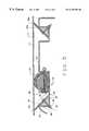
- FIG. 1is a longitudinal cross-sectional view of an end portion of a tank showing a piston in partial cross-section, movable within the tank, in accordance with the present invention
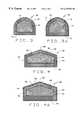
- FIG. 2is an enlarged sectional view of a portion of the piston showing the seal mounted in its channel;
- FIG. 2Ais an enlarged sectional view of a portion of the piston showing an alternate embodiment of the present seal mounted in its channel;
- FIG. 3is an enlarged sectional view of the seal depicted in FIGS. 1 and 2;
- FIG. 3Ais an enlarges sectional view of the seal of FIG. 3 with an optional friction reducing layer;
- FIG. 4is an enlarged sectional view of an alternate embodiment of the present seal depicted in FIGS. 1 and 2A;
- FIG. 4Ais an enlarged sectional view of the seal of FIG. 4 with an optional friction reducing layer
- FIG. 5is an enlarged sectional view of a portion of the piston showing the seal mounted in its channel with a pair of wipers coupled to the piston body;
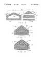
- FIG. 6is an exploded sectional view of the components in the preferred embodiment of the seal.
- FIG. 7is an enlarged sectional view of the assembled seal of FIG. 6.
- FIG. 8is an enlarged sectional view of the seal of FIG. 7 with an optional friction reducing layer.
- FIG. 1there is shown a portion of a tank, designated 10 , defined by a generally cylindrical wall 11 , preferably formed of a suitable metal in order to effectively contain the material to be stored and/or transported therein (hereinafter “the material”).
- the wall 11defines a generally cylindrical interior volume or space 12 of the tank that is bounded by an interior or inner surface 14 of the wall 11 .
- the tank 10has an opening 16 at one end thereof, which for convenience will be deemed the front of the tank 10 .
- the opening 16is a combination inlet and outlet for introducing and removing the material respectfully into and out of the tank volume 12 .
- a tank piston 18Disposed within the volume 12 is a tank piston 18 of a generally cylindrical configuration and preferably formed of a suitable metal.
- the outside diameter of the piston 18is slightly less than the inner diameter of the tank 10 such that the piston 18 is movable back and forth within the tank 10 .
- the piston 18divides the whole interior volume 12 of the tank 10 into a front volume 22 forward of a curved front portion 20 of the piston 18 and a rear volume 21 rearward of a curved rear portion 19 of the piston 18 .
- the front and rear volumes 22 , 21are variable depending on the position of the piston 18 within the tank.
- the front volume 22receives and holds the material. The more material, the larger front volume 22 becomes with the rear volume 21 becoming less as the piston 18 moves rearward.
- the piston 18is defined by the curved front portion or wall 20 and the rear portion or wall 19 and a middle, generally cylindrical portion or wall 23 . Disposed on the outside surface or periphery 24 of the wall 23 of the middle portion 23 are two sets of anti-canting pads 26 and 28 .
- the anti-canting pads 26are disposed in an annular pattern about the piston 18 proximate the front portion 20 while the canting pads 28 are disposed in an annular pattern about the piston 18 proximate the rear portion 19 .
- the anti-canting pads 26 , 28extend radially outward from the surface 24 and are respectfully fastened thereto by bolts that extend through the wall 23 and are secured by nuts 27 , 29 on the inner surface 25 .
- the anti-canting pads 26 , 28abut the inner surface 14 of the wall 11 to prevent the piston 18 from canting within the tank 10 .
- the padsare preferably of a low friction material (e.g. nylon) to permit the piston 18 to move freely within the tank 10 .
- a low friction materiale.g. nylon
- alternate devicesmay be used to accomplish this result.
- the pads 26 , 28are axially and circumferentially spaced on the piston surface 24 accordingly.
- FIG. 2Ashows an alternate seal structure 36 disposed within channel 35 .
- the seal 68is preferably formed of an elastic material such as rubber, VITON®, neoprene, nitrile, or other suitable material.
- the seal 68is defined by an annular base 70 formed of a rubber as again described above, to which is coupled an annular dome-shaped (in cross-section) cap or crown 72 .
- the cap 72 and base 70define an annular cavity or chamber 74 which is filled with an open celled foam 76 .
- open celled foam material 76may be a rubber compound, polyurethane, or the like which is elastically compressible, to provide and impart a resiliency effect to the seal structure 68 .
- a gel, such as silicamay be used in place of the open celled foam material 76 .
- an optional an outer layer 77may be disposed about the seal 68 to reduce the kinetic coefficient of friction as the seal moves across the inside surface 14 of the tank 10 .
- the outer layer 77may be made of any suitable low friction material, such as teflon, rayon, nylon, or any high-density alkenes. It is preferable that such outer layer 77 be shrink wrapped around the seal 68 to provide the best friction reduction.
- FIGS. 2A, 4 , and 4 Athere is shown an alternative embodiment of a seal, generally designated 36 that may be used. It should here be understood that various seal configurations may work, as long as they have an interior cavity filled with an open celled foam as described above with reference to the seal 36 .
- the seal 36is defined by an annular base portion 50 , a first or left perpendicular annular wall portion 52 , a second or right perpendicular annular wall portion 54 , a first or left angled annular wall portion 56 , and a second or right angled annular wall portion 58 .
- the first perpendicular wall portion 52is attached to the base portion proximate one end thereof, while the second perpendicular wall portion 54 is attached to the base portion proximate another end thereof.
- the first angled wall portion 56is attached at one end to a top end of the first perpendicular wall portion 52
- the second angled wall portion 58is attached at one end to a top end of the second perpendicular wall portion 54 .
- the other ends of the first and second angled wall portions 56 , 58are joined together to form an apex 60 .
- the wall portionsare integrally formed such that the seal 36 is substantially seamless.
- the wall portions 52 , 54 , 56 , 58form a crown or cap, and an annular interior hollow, cavity, or chamber 62 that is filled with an open celled foam material 64 .
- open celled foam material 64may as described above in reference to celled foam material 76 .
- An optional outer layer 65may be disposed around seal 36 in the same manner as outer layer 77 .
- seal configurationsmay work, as long as they have an interior cavity filled with an open celled foam as described above with reference to the seals 36 and 68 .
- a plurality of cotter pins 80may be used to further prevent the seal from rolling out of the channel 35 .
- the cotter pins 80may be inserted through two sidewalls 44 , 48 defined by channel 35 and through the celled foam material of the seal.
- the seal 36is where the apex 60 is abutting the inner surface 14 , and the first and second angled wall portions 56 , 58 are radially downwardly compressed. Compression of the seal 36 between the piston and the inner surface of the tank prevents the intrusion of the material from the front volume 22 and the rear volume 21 . Also, because the cavity 62 of the seal 36 is filled with the resilient foam material 64 , the walls of the seal tend to radially outwardly expand, particularly if the base 50 is made thicker than the remaining walls. Thus, if a puncture or rupture occurs in the seal, there will be no deflation of the seal as in “air seals” nor a significant loss of the sealing effect. It should be recognized that after a certain amount of wear and tear, even the present seal would need replacement. However, the lifetime of the present seal is generally greater than the “air seals.”
- the piston 18may include an essentially annular wiper generally designated 38 preferably formed of a plastic such as nylon or the like.
- the wiper 38 in the embodiment shownextends about the piston 18 from the area forming a juncture between the curved front portion 20 and the cylindrical middle portion 23 .
- the wiper 38is angled upwardly relative to a major axis of the piston 18 towards the inner surface of the tank. If a wiper 38 is used it should extend at a 45 ⁇ angle relative to the piston axis.
- the end of the wiper 38 abutting the inner surface of the tankhas a bevel 39 such that a flat portion of the bevel abuts the inner surface of the tank. This provides a wiping or scraping action against the inner surface of the tank to clean the same.
- the wiper 38is mounted to the piston 18 by disposing a lower portion 82 of the wiper 38 within a circumferential groove or channel 84 axially spaced parallel to the seal channel 35 .
- the channel 84defines two sidewalls 86 , 88 .
- the sidewall 86 closest to the front of the piston 18should be at 45° relative to the piston axis. If the sidewall 86 is vertical or at an angle other than 45°, a fill material 90 should be disposed against the sidewall 86 as shown in FIG. 5 .
- the fill material 90may be metal, polymer, or any other material that can provide a smooth 45° surface for the wiper 38 .
- the wiper 38may then be secured to the fill material 90 or angled sidewall as appropriate by means of a screw or nut 92 and a bolt 94 .
- a second wiper 38 amay be disposed near the rear of the piston 18 , in mirror image to the first wiper 38 (i.e. the bevel 39 a of the rear wiper 38 a is oriented in the opposite direction of wiper 38 ).
- the seal 100is similar to the seal 36 of FIGS. 2A, 4 , and 2 A. Unlike the seal 36 , the seal 100 has an annular base portion 102 that is the same thickness as the wall portions, 104 , 106 , 108 , and 110 . A thickness of 0.375′′ has been discovered to be effective.
- the annular chamber 112 defined by the annular base 102 and the wall portions 104 , 106 , 108 , and 110is filled with the support assembly 114 .
- the support assembly 114comprises one or more open cell foam material layers 116 , 118 and a support strip 120 .
- the support assembly 114is combined into an integral part by placing an adhesive between the various components layers—the foam material layers 116 , and 118 and the support strip 120 . After the adhesive cures, the edges of the support assembly 114 are cut down, possibly with a band saw, to match the approximate profile of the annular chamber 112 .
- FIG. 6shows how the cuting has left beveled surfaces 122 on the support assembly 114 to correspond to the wall portions 106 and 108 .
- the support strip 120extends beyond the open cell foam material layers 116 , 118 . This allows the entire support assembly 114 to be pulled through the annular chamber 112 , the open cell foam material layers 116 , 118 , thus being compressed during this process. After the support assembly 114 is in place, it is given time to relax, the protruding portion is removed after which the ends of the two ends of the seal 100 may be glued together thereby forming a ring.
- the support strip 120is preferably made of the same material as the base portion 102 (and wall portions 104 , 106 , 108 , 110 ).
- the support strip 120performs two functions. It provides rigidity to the support assembly 114 facilitating its insertion into the annular chamber 112 . It also provides extra support to the base portion 102 to limit the amount of bowing that occurs. In FIGS. 7 and 8 it can be seen that the base portion 102 will bow slightly even with the support strip 120 . By the time the seal is formed into a ring and placed around the piston, this bowing becomes negligible.
- FIG. 8shows that the optional outer layer 124 may be added to this embodiment similar to the outer layer 77 of FIG. 3 A.
Landscapes
- Engineering & Computer Science (AREA)
- General Engineering & Computer Science (AREA)
- Mechanical Engineering (AREA)
- Sealing Devices (AREA)
- Toys (AREA)
- Ink Jet (AREA)
- Sealing Material Composition (AREA)
- Coating Apparatus (AREA)
- Containers And Packaging Bodies Having A Special Means To Remove Contents (AREA)
- Electrical Discharge Machining, Electrochemical Machining, And Combined Machining (AREA)
- Gasket Seals (AREA)
Abstract
Description
Claims (19)
Priority Applications (11)
| Application Number | Priority Date | Filing Date | Title |
|---|---|---|---|
| US09/476,166US6325384B1 (en) | 1997-09-10 | 1999-12-30 | Tank piston with improved seal and wiper |
| PT00989327TPT1247032E (en) | 1999-12-30 | 2000-12-19 | TANK TRACK WITH AN IMPROVED SEAL |
| AT00989327TATE329183T1 (en) | 1999-12-30 | 2000-12-19 | CONTAINER PISTON WITH IMPROVED SEAL |
| EP00989327AEP1247032B1 (en) | 1999-12-30 | 2000-12-19 | Tank piston with improved seal |
| ES00989327TES2269221T3 (en) | 1999-12-30 | 2000-12-19 | DEPOSIT PISTON WITH IMPROVED SEALING BOARD. |
| PCT/US2000/034527WO2001050043A1 (en) | 1999-12-30 | 2000-12-19 | Tank piston with improved seal and wiper |
| DE60028611TDE60028611T2 (en) | 1999-12-30 | 2000-12-19 | CONTAINER PISTON WITH IMPROVED SEAL |
| DK00989327TDK1247032T3 (en) | 1999-12-30 | 2000-12-19 | Tank piston with improved seal |
| MXPA02006482AMXPA02006482A (en) | 1999-12-30 | 2000-12-19 | Tank piston with improved seal and wiper. |
| HK03102520.2AHK1051062B (en) | 1999-12-30 | 2000-12-19 | Tank piston with improved seal |
| CA002395677ACA2395677C (en) | 1999-12-30 | 2000-12-19 | Tank piston with improved seal and wiper |
Applications Claiming Priority (2)
| Application Number | Priority Date | Filing Date | Title |
|---|---|---|---|
| US08/926,821US6027123A (en) | 1997-09-10 | 1997-09-10 | Tank piston with improved seal and wiper |
| US09/476,166US6325384B1 (en) | 1997-09-10 | 1999-12-30 | Tank piston with improved seal and wiper |
Related Parent Applications (1)
| Application Number | Title | Priority Date | Filing Date |
|---|---|---|---|
| US08/926,821Continuation-In-PartUS6027123A (en) | 1997-09-10 | 1997-09-10 | Tank piston with improved seal and wiper |
Publications (1)
| Publication Number | Publication Date |
|---|---|
| US6325384B1true US6325384B1 (en) | 2001-12-04 |
Family
ID=23890763
Family Applications (1)
| Application Number | Title | Priority Date | Filing Date |
|---|---|---|---|
| US09/476,166Expired - LifetimeUS6325384B1 (en) | 1997-09-10 | 1999-12-30 | Tank piston with improved seal and wiper |
Country Status (10)
| Country | Link |
|---|---|
| US (1) | US6325384B1 (en) |
| EP (1) | EP1247032B1 (en) |
| AT (1) | ATE329183T1 (en) |
| CA (1) | CA2395677C (en) |
| DE (1) | DE60028611T2 (en) |
| DK (1) | DK1247032T3 (en) |
| ES (1) | ES2269221T3 (en) |
| MX (1) | MXPA02006482A (en) |
| PT (1) | PT1247032E (en) |
| WO (1) | WO2001050043A1 (en) |
Cited By (37)
| Publication number | Priority date | Publication date | Assignee | Title |
|---|---|---|---|---|
| US20030122317A1 (en)* | 2000-05-19 | 2003-07-03 | Thomas Andersson | Method for manufacturing an elastic sealing ring and sealing ring manufactured according to the method |
| US6601852B1 (en)* | 1999-11-19 | 2003-08-05 | Hilti Aktiengesellschaft | Method and apparatus for sealing a space |
| US20040032092A1 (en)* | 2002-08-16 | 2004-02-19 | Visteon Global Technologies, Inc. | Low permeation sealing member |
| US20040069813A1 (en)* | 2002-10-10 | 2004-04-15 | Gene Brisson | Piston and seal for a storage tank |
| US20040195270A1 (en)* | 2001-03-23 | 2004-10-07 | Coleman Clarence B. | Horizontal container with a moveable bulkhead follower for the storage and transport of bulk viscous material |
| US20050232072A1 (en)* | 2004-03-31 | 2005-10-20 | Thibodeau Robert D | Refillable material transfer system |
| US7159508B1 (en)* | 2005-10-11 | 2007-01-09 | Michael F. Birsner | Tank piston seal and stabilizing system |
| US20070199957A1 (en)* | 2006-02-27 | 2007-08-30 | Aerojet-General Corporation | Piston tank with compound piston for high loading and expulsion efficiency |
| US20080041635A1 (en)* | 2006-08-18 | 2008-02-21 | Atlas Copco Secoroc Llc | Seal for an earth bit |
| US7473221B2 (en) | 2000-10-19 | 2009-01-06 | Applied Medical Resources Corporation | Surgical access apparatus and method |
| US7650887B2 (en) | 2002-06-05 | 2010-01-26 | Applied Medical Resources Corporation | Wound retractor |
| US7704207B2 (en) | 2005-10-14 | 2010-04-27 | Applied Medical Resources Corporation | Circular surgical retractor |
| US7951076B2 (en) | 2003-02-25 | 2011-05-31 | Applied Medical Resources Corporation | Surgical access system |
| US8109873B2 (en) | 2007-05-11 | 2012-02-07 | Applied Medical Resources Corporation | Surgical retractor with gel pad |
| US20120043331A1 (en)* | 2009-05-08 | 2012-02-23 | Nok Corporation | Water-proof structure for opening of case of appliance |
| US8157835B2 (en) | 2001-08-14 | 2012-04-17 | Applied Medical Resouces Corporation | Access sealing apparatus and method |
| US8187177B2 (en) | 2003-09-17 | 2012-05-29 | Applied Medical Resources Corporation | Surgical instrument access device |
| US8226552B2 (en) | 2007-05-11 | 2012-07-24 | Applied Medical Resources Corporation | Surgical retractor |
| US8262568B2 (en) | 2008-10-13 | 2012-09-11 | Applied Medical Resources Corporation | Single port access system |
| US8343047B2 (en) | 2008-01-22 | 2013-01-01 | Applied Medical Resources Corporation | Surgical instrument access device |
| US8388526B2 (en) | 2001-10-20 | 2013-03-05 | Applied Medical Resources Corporation | Wound retraction apparatus and method |
| US8703034B2 (en) | 2001-08-14 | 2014-04-22 | Applied Medical Resources Corporation | Method of making a tack-free gel |
| US8758236B2 (en) | 2011-05-10 | 2014-06-24 | Applied Medical Resources Corporation | Wound retractor |
| US9067728B2 (en) | 2012-03-01 | 2015-06-30 | Clasen Quality Coatings, Inc. | Container including a magnetically operated scraper |
| US9289115B2 (en) | 2010-10-01 | 2016-03-22 | Applied Medical Resources Corporation | Natural orifice surgery system |
| US9289200B2 (en) | 2010-10-01 | 2016-03-22 | Applied Medical Resources Corporation | Natural orifice surgery system |
| US9642608B2 (en) | 2014-07-18 | 2017-05-09 | Applied Medical Resources Corporation | Gels having permanent tack free coatings and method of manufacture |
| US9717522B2 (en) | 2009-08-31 | 2017-08-01 | Applied Medical Resources Corporation | Multi-functional surgical access system |
| US9949730B2 (en) | 2014-11-25 | 2018-04-24 | Applied Medical Resources Corporation | Circumferential wound retraction with support and guidance structures |
| US10172641B2 (en) | 2014-08-15 | 2019-01-08 | Applied Medical Resources Corporation | Natural orifice surgery system |
| US10221059B2 (en) | 2004-03-31 | 2019-03-05 | Ch&I Technologies, Inc. | Refillable material transfer system |
| US10368908B2 (en) | 2015-09-15 | 2019-08-06 | Applied Medical Resources Corporation | Surgical robotic access system |
| US10563763B1 (en) | 2017-03-31 | 2020-02-18 | Piston Tank Corporation | Tank piston with improved seal and cover |
| US10575840B2 (en) | 2015-10-07 | 2020-03-03 | Applied Medical Resources Corporation | Wound retractor with multi-segment outer ring |
| US10674896B2 (en) | 2016-09-12 | 2020-06-09 | Applied Medical Resources Corporation | Surgical robotic access system for irregularly shaped robotic actuators and associated robotic surgical instruments |
| US10758850B2 (en)* | 2018-08-01 | 2020-09-01 | Parker-Hannifin Corporation | Filter cartridge and/or multiple-diameter multiple stage filter coalescer separator |
| US11471142B2 (en) | 2013-03-15 | 2022-10-18 | Applied Medical Resources Corporation | Mechanical gel surgical access device |
Families Citing this family (1)
| Publication number | Priority date | Publication date | Assignee | Title |
|---|---|---|---|---|
| GB202113150D0 (en) | 2019-05-03 | 2021-10-27 | Oil States Ind Uk Ltd | An Elastically deformable resilient annular seal for installation into an annular groove |
Citations (24)
| Publication number | Priority date | Publication date | Assignee | Title |
|---|---|---|---|---|
| US2144082A (en)* | 1936-05-19 | 1939-01-17 | Us Rubber Co | Packing strip |
| US2859061A (en) | 1954-09-17 | 1958-11-04 | William P Reid | Composite sealing ring and method of making the same |
| US3043468A (en) | 1960-02-23 | 1962-07-10 | Gen Am Transport | Sealing mechanisms for storage tanks |
| US3055533A (en)* | 1961-01-23 | 1962-09-25 | Chicago Bridge & Iron Co | Primary seal for floating roofs |
| US3125346A (en) | 1964-03-17 | Method of sealing the space between the wall | ||
| US3307733A (en) | 1965-02-12 | 1967-03-07 | Gen Am Transport | Sealing mechanisms for storage tanks |
| US3828988A (en) | 1973-04-04 | 1974-08-13 | Bervy Inc | Tank for bulk transport and storage of semisolid materials |
| US3926332A (en)* | 1973-02-14 | 1975-12-16 | Nippon Kakokicompany Limited | Sealing structure for a liquid storage vessel having a floating head |
| US4004708A (en)* | 1975-12-19 | 1977-01-25 | Philadelphia Suburban Corporation | Fire-responsive tank top |
| US4130217A (en)* | 1977-09-27 | 1978-12-19 | Pittsburgh-Des Moines Steel Company | Seal arrangement for floating roof storage tanks |
| US4147274A (en)* | 1978-05-12 | 1979-04-03 | Shell Oil Company | Floating roof tank seal |
| US4178000A (en) | 1977-03-25 | 1979-12-11 | Vereinigte Osterreichische Eisen- Und Stahlwerke - Alpine Montan Aktiengesellschaft | Sealing provided between the walls of a cooled continuous mould and the head of a starter bar |
| US4355736A (en) | 1978-03-01 | 1982-10-26 | Schumacker Henri J J | Device for dispensing a liquid or a paste in a finely divided manner |
| US4371090A (en) | 1980-11-03 | 1983-02-01 | Gatx Tank Erection Corporation | Secondary seal for floating roof storage tank |
| US4449713A (en)* | 1980-10-17 | 1984-05-22 | Hayakawa Rubber Company Limited | Aqueously-swelling water stopper and a process of stopping water thereby |
| US4532800A (en)* | 1983-12-01 | 1985-08-06 | Fabricated Metals, Inc. | Level indicator for liquid container with a follower |
| US4721235A (en) | 1986-08-08 | 1988-01-26 | Watson M Burnell | Tank for transport and storage of semisolid and fluid materials |
| DE3725360A1 (en)* | 1987-07-30 | 1989-02-09 | Riexinger Tuerenwerk | Accident-prevention guard strip for automatically actuable gates (shutters) and doors |
| US4842160A (en)* | 1986-04-17 | 1989-06-27 | Piso Bastiaan D F | Floating covering for liquid storage tank |
| US5114054A (en) | 1990-07-19 | 1992-05-19 | Watson M Burnell | Tank piston with teflon sheathed packing member |
| US5137283A (en)* | 1991-06-27 | 1992-08-11 | Itt Corporation | Thermally conductive gasket device |
| US5290045A (en)* | 1991-03-01 | 1994-03-01 | C.I. Kasei Co., Ltd. | Seal for joint, and method of installing same seal |
| US5341726A (en)* | 1993-03-31 | 1994-08-30 | Watson M Burnell | Piston for tank |
| US5385081A (en) | 1993-09-09 | 1995-01-31 | Arde Incorporated | Fluid storage tank employing a shear seal |
Family Cites Families (2)
| Publication number | Priority date | Publication date | Assignee | Title |
|---|---|---|---|---|
| NL282169A (en)* | 1962-01-19 | |||
| US6027123A (en)* | 1997-09-10 | 2000-02-22 | Cbw Transport Services, Inc. | Tank piston with improved seal and wiper |
- 1999
- 1999-12-30USUS09/476,166patent/US6325384B1/ennot_activeExpired - Lifetime
- 2000
- 2000-12-19DEDE60028611Tpatent/DE60028611T2/ennot_activeExpired - Lifetime
- 2000-12-19DKDK00989327Tpatent/DK1247032T3/enactive
- 2000-12-19WOPCT/US2000/034527patent/WO2001050043A1/enactiveIP Right Grant
- 2000-12-19CACA002395677Apatent/CA2395677C/ennot_activeExpired - Lifetime
- 2000-12-19PTPT00989327Tpatent/PT1247032E/enunknown
- 2000-12-19ESES00989327Tpatent/ES2269221T3/ennot_activeExpired - Lifetime
- 2000-12-19ATAT00989327Tpatent/ATE329183T1/enactive
- 2000-12-19MXMXPA02006482Apatent/MXPA02006482A/enactiveIP Right Grant
- 2000-12-19EPEP00989327Apatent/EP1247032B1/ennot_activeExpired - Lifetime
Patent Citations (24)
| Publication number | Priority date | Publication date | Assignee | Title |
|---|---|---|---|---|
| US3125346A (en) | 1964-03-17 | Method of sealing the space between the wall | ||
| US2144082A (en)* | 1936-05-19 | 1939-01-17 | Us Rubber Co | Packing strip |
| US2859061A (en) | 1954-09-17 | 1958-11-04 | William P Reid | Composite sealing ring and method of making the same |
| US3043468A (en) | 1960-02-23 | 1962-07-10 | Gen Am Transport | Sealing mechanisms for storage tanks |
| US3055533A (en)* | 1961-01-23 | 1962-09-25 | Chicago Bridge & Iron Co | Primary seal for floating roofs |
| US3307733A (en) | 1965-02-12 | 1967-03-07 | Gen Am Transport | Sealing mechanisms for storage tanks |
| US3926332A (en)* | 1973-02-14 | 1975-12-16 | Nippon Kakokicompany Limited | Sealing structure for a liquid storage vessel having a floating head |
| US3828988A (en) | 1973-04-04 | 1974-08-13 | Bervy Inc | Tank for bulk transport and storage of semisolid materials |
| US4004708A (en)* | 1975-12-19 | 1977-01-25 | Philadelphia Suburban Corporation | Fire-responsive tank top |
| US4178000A (en) | 1977-03-25 | 1979-12-11 | Vereinigte Osterreichische Eisen- Und Stahlwerke - Alpine Montan Aktiengesellschaft | Sealing provided between the walls of a cooled continuous mould and the head of a starter bar |
| US4130217A (en)* | 1977-09-27 | 1978-12-19 | Pittsburgh-Des Moines Steel Company | Seal arrangement for floating roof storage tanks |
| US4355736A (en) | 1978-03-01 | 1982-10-26 | Schumacker Henri J J | Device for dispensing a liquid or a paste in a finely divided manner |
| US4147274A (en)* | 1978-05-12 | 1979-04-03 | Shell Oil Company | Floating roof tank seal |
| US4449713A (en)* | 1980-10-17 | 1984-05-22 | Hayakawa Rubber Company Limited | Aqueously-swelling water stopper and a process of stopping water thereby |
| US4371090A (en) | 1980-11-03 | 1983-02-01 | Gatx Tank Erection Corporation | Secondary seal for floating roof storage tank |
| US4532800A (en)* | 1983-12-01 | 1985-08-06 | Fabricated Metals, Inc. | Level indicator for liquid container with a follower |
| US4842160A (en)* | 1986-04-17 | 1989-06-27 | Piso Bastiaan D F | Floating covering for liquid storage tank |
| US4721235A (en) | 1986-08-08 | 1988-01-26 | Watson M Burnell | Tank for transport and storage of semisolid and fluid materials |
| DE3725360A1 (en)* | 1987-07-30 | 1989-02-09 | Riexinger Tuerenwerk | Accident-prevention guard strip for automatically actuable gates (shutters) and doors |
| US5114054A (en) | 1990-07-19 | 1992-05-19 | Watson M Burnell | Tank piston with teflon sheathed packing member |
| US5290045A (en)* | 1991-03-01 | 1994-03-01 | C.I. Kasei Co., Ltd. | Seal for joint, and method of installing same seal |
| US5137283A (en)* | 1991-06-27 | 1992-08-11 | Itt Corporation | Thermally conductive gasket device |
| US5341726A (en)* | 1993-03-31 | 1994-08-30 | Watson M Burnell | Piston for tank |
| US5385081A (en) | 1993-09-09 | 1995-01-31 | Arde Incorporated | Fluid storage tank employing a shear seal |
Cited By (105)
| Publication number | Priority date | Publication date | Assignee | Title |
|---|---|---|---|---|
| US6601852B1 (en)* | 1999-11-19 | 2003-08-05 | Hilti Aktiengesellschaft | Method and apparatus for sealing a space |
| US20030122317A1 (en)* | 2000-05-19 | 2003-07-03 | Thomas Andersson | Method for manufacturing an elastic sealing ring and sealing ring manufactured according to the method |
| US8672839B2 (en) | 2000-10-19 | 2014-03-18 | Applied Medical Resource Corporation | Surgical access apparatus and method |
| US7473221B2 (en) | 2000-10-19 | 2009-01-06 | Applied Medical Resources Corporation | Surgical access apparatus and method |
| US8016755B2 (en) | 2000-10-19 | 2011-09-13 | Applied Medical Resources Corporation | Surgical access apparatus and method |
| US8070676B2 (en) | 2000-10-19 | 2011-12-06 | Applied Medical Resources Corporation | Surgical access apparatus and method |
| US8496581B2 (en) | 2000-10-19 | 2013-07-30 | Applied Medical Resources Corporation | Surgical access apparatus and method |
| US8911366B2 (en) | 2000-10-19 | 2014-12-16 | Applied Medical Resources Corporation | Surgical access apparatus and method |
| US8105234B2 (en) | 2000-10-19 | 2012-01-31 | Applied Medical Resources Corporation | Surgical access apparatus and method |
| US7481765B2 (en) | 2000-10-19 | 2009-01-27 | Applied Medical Resources Corporation | Surgical access apparatus and method |
| US20040195270A1 (en)* | 2001-03-23 | 2004-10-07 | Coleman Clarence B. | Horizontal container with a moveable bulkhead follower for the storage and transport of bulk viscous material |
| US9669153B2 (en) | 2001-08-14 | 2017-06-06 | Applied Medical Resources Corporation | Method of manufacturing a tack-free gel for a surgical device |
| US8703034B2 (en) | 2001-08-14 | 2014-04-22 | Applied Medical Resources Corporation | Method of making a tack-free gel |
| US8157835B2 (en) | 2001-08-14 | 2012-04-17 | Applied Medical Resouces Corporation | Access sealing apparatus and method |
| US8870904B2 (en) | 2001-08-14 | 2014-10-28 | Applied Medical Resources Corporation | Access sealing apparatus and method |
| US9878140B2 (en) | 2001-08-14 | 2018-01-30 | Applied Medical Resources Corporation | Access sealing apparatus and method |
| US8388526B2 (en) | 2001-10-20 | 2013-03-05 | Applied Medical Resources Corporation | Wound retraction apparatus and method |
| US8235054B2 (en) | 2002-06-05 | 2012-08-07 | Applied Medical Resources Corporation | Wound retractor |
| US10507017B2 (en) | 2002-06-05 | 2019-12-17 | Applied Medical Resources Corporation | Wound retractor |
| US8973583B2 (en) | 2002-06-05 | 2015-03-10 | Applied Medical Resources Corporation | Wound retractor |
| US9561024B2 (en) | 2002-06-05 | 2017-02-07 | Applied Medical Resources Corporation | Wound retractor |
| US7650887B2 (en) | 2002-06-05 | 2010-01-26 | Applied Medical Resources Corporation | Wound retractor |
| US7913697B2 (en) | 2002-06-05 | 2011-03-29 | Applied Medical Resources Corporation | Wound retractor |
| US20040032092A1 (en)* | 2002-08-16 | 2004-02-19 | Visteon Global Technologies, Inc. | Low permeation sealing member |
| US6755422B2 (en)* | 2002-08-16 | 2004-06-29 | Visteon Global Technologies, Inc. | Low permeation sealing member |
| US20040069813A1 (en)* | 2002-10-10 | 2004-04-15 | Gene Brisson | Piston and seal for a storage tank |
| US6916025B2 (en) | 2002-10-10 | 2005-07-12 | Piston Technology, Llc | Piston and seal for a storage tank |
| US7951076B2 (en) | 2003-02-25 | 2011-05-31 | Applied Medical Resources Corporation | Surgical access system |
| US9295459B2 (en) | 2003-02-25 | 2016-03-29 | Applied Medical Resources Corporation | Surgical access system |
| US8932214B2 (en) | 2003-02-25 | 2015-01-13 | Applied Medical Resources Corporation | Surgical access system |
| US8187177B2 (en) | 2003-09-17 | 2012-05-29 | Applied Medical Resources Corporation | Surgical instrument access device |
| US8357086B2 (en) | 2003-09-17 | 2013-01-22 | Applied Medical Resources Corporation | Surgical instrument access device |
| US20080302833A1 (en)* | 2004-03-31 | 2008-12-11 | Ch&I Technologies, Inc. | Refillable material transfer system |
| US7762434B2 (en) | 2004-03-31 | 2010-07-27 | Ch&I Technologies, Inc. | Refillable material transfer system |
| US7997445B2 (en) | 2004-03-31 | 2011-08-16 | Ch&I Technologies, Inc. | Refillable material transfer system |
| US10221059B2 (en) | 2004-03-31 | 2019-03-05 | Ch&I Technologies, Inc. | Refillable material transfer system |
| CN1956916B (en)* | 2004-03-31 | 2011-06-01 | Ch&I技术公司 | Refillable Material Transfer System |
| US20050232072A1 (en)* | 2004-03-31 | 2005-10-20 | Thibodeau Robert D | Refillable material transfer system |
| US8640918B2 (en) | 2004-03-31 | 2014-02-04 | Ch&I Technologies, Inc. | Refillable material transfer system |
| EP1737781B1 (en)* | 2004-03-31 | 2013-03-20 | C.H. & I. Technologies, Inc. | Refillable material transfer system |
| US7159508B1 (en)* | 2005-10-11 | 2007-01-09 | Michael F. Birsner | Tank piston seal and stabilizing system |
| US7727146B2 (en) | 2005-10-14 | 2010-06-01 | Applied Medical Resources | Wound retractor with gel cap |
| US7883461B2 (en) | 2005-10-14 | 2011-02-08 | Applied Medical Resources | Wound retractor with gel cap |
| US9474519B2 (en) | 2005-10-14 | 2016-10-25 | Applied Medical Resources Corporation | Hand access laparoscopic device |
| US7892172B2 (en) | 2005-10-14 | 2011-02-22 | Applied Medical Resources Corporation | Circular surgical retractor |
| US8308639B2 (en) | 2005-10-14 | 2012-11-13 | Applied Medical Resources Corporation | Split hoop wound retractor with gel pad |
| US8267858B2 (en) | 2005-10-14 | 2012-09-18 | Applied Medical Resources Corporation | Wound retractor with gel cap |
| US8414487B2 (en) | 2005-10-14 | 2013-04-09 | Applied Medical Resources Corporation | Circular surgical retractor |
| US7878974B2 (en) | 2005-10-14 | 2011-02-01 | Applied Medical Resources Corporation | Hand access laparoscopic device |
| US7749415B2 (en) | 2005-10-14 | 2010-07-06 | Applied Medical Resources Corporation | Method of making a hand access laparoscopic device |
| US7909760B2 (en) | 2005-10-14 | 2011-03-22 | Applied Medical Resources Corporation | Split hoop wound retractor with gel pad |
| US8647265B2 (en) | 2005-10-14 | 2014-02-11 | Applied Medical Resources Corporation | Hand access laparoscopic device |
| US9101354B2 (en) | 2005-10-14 | 2015-08-11 | Applied Medical Resources Corporation | Wound retractor with gel cap |
| US7736306B2 (en) | 2005-10-14 | 2010-06-15 | Applied Medical Resources Corporation | Hand access laparoscopic device |
| US7815567B2 (en) | 2005-10-14 | 2010-10-19 | Applied Medical Resources, Corporation | Split hoop wound retractor |
| US9017254B2 (en) | 2005-10-14 | 2015-04-28 | Applied Medical Resources Corporation | Hand access laparoscopic device |
| US7704207B2 (en) | 2005-10-14 | 2010-04-27 | Applied Medical Resources Corporation | Circular surgical retractor |
| US9649102B2 (en) | 2005-10-14 | 2017-05-16 | Applied Medical Resources Corporation | Wound retractor with split hoops |
| US8313431B2 (en) | 2005-10-14 | 2012-11-20 | Applied Medical Resources Corporation | Split hoop wound retractor |
| US7621429B2 (en) | 2006-02-27 | 2009-11-24 | Aerojet- General Corporation | Piston tank with compound piston for high loading and expulsion efficiency |
| US20070199957A1 (en)* | 2006-02-27 | 2007-08-30 | Aerojet-General Corporation | Piston tank with compound piston for high loading and expulsion efficiency |
| US20080041635A1 (en)* | 2006-08-18 | 2008-02-21 | Atlas Copco Secoroc Llc | Seal for an earth bit |
| US8961410B2 (en) | 2007-05-11 | 2015-02-24 | Applied Medical Resources Corporation | Surgical retractor with gel pad |
| US8109873B2 (en) | 2007-05-11 | 2012-02-07 | Applied Medical Resources Corporation | Surgical retractor with gel pad |
| US8226552B2 (en) | 2007-05-11 | 2012-07-24 | Applied Medical Resources Corporation | Surgical retractor |
| US8343047B2 (en) | 2008-01-22 | 2013-01-01 | Applied Medical Resources Corporation | Surgical instrument access device |
| US8721537B2 (en) | 2008-10-13 | 2014-05-13 | Applied Medical Resources Corporation | Single port access system |
| US8480575B2 (en) | 2008-10-13 | 2013-07-09 | Applied Medical Resources Corporation | Single port access system |
| US8262568B2 (en) | 2008-10-13 | 2012-09-11 | Applied Medical Resources Corporation | Single port access system |
| US8894571B2 (en) | 2008-10-13 | 2014-11-25 | Applied Medical Resources Corporation | Single port access system |
| US20120043331A1 (en)* | 2009-05-08 | 2012-02-23 | Nok Corporation | Water-proof structure for opening of case of appliance |
| US9743954B2 (en) | 2009-08-31 | 2017-08-29 | Applied Medical Resources Corporation | Multifunctional surgical access system |
| US9717522B2 (en) | 2009-08-31 | 2017-08-01 | Applied Medical Resources Corporation | Multi-functional surgical access system |
| US11510695B2 (en) | 2009-08-31 | 2022-11-29 | Applied Medical Resources Corporation | Multifunctional surgical access system |
| US10376282B2 (en) | 2010-10-01 | 2019-08-13 | Applied Medical Resources Corporation | Natural orifice surgery system |
| US10271875B2 (en) | 2010-10-01 | 2019-04-30 | Applied Medical Resources Corporation | Natural orifice surgery system |
| US12089872B2 (en) | 2010-10-01 | 2024-09-17 | Applied Medical Resources Corporation | Natural orifice surgery system |
| US9289200B2 (en) | 2010-10-01 | 2016-03-22 | Applied Medical Resources Corporation | Natural orifice surgery system |
| US9872702B2 (en) | 2010-10-01 | 2018-01-23 | Applied Medical Resources Corporation | Natural orifice surgery system |
| US9289115B2 (en) | 2010-10-01 | 2016-03-22 | Applied Medical Resources Corporation | Natural orifice surgery system |
| US11123102B2 (en) | 2010-10-01 | 2021-09-21 | Applied Medical Resources Corporation | Natural orifice surgery system |
| US8758236B2 (en) | 2011-05-10 | 2014-06-24 | Applied Medical Resources Corporation | Wound retractor |
| US9241697B2 (en) | 2011-05-10 | 2016-01-26 | Applied Medical Resources Corporation | Wound retractor |
| US9192366B2 (en) | 2011-05-10 | 2015-11-24 | Applied Medical Resources Corporation | Wound retractor |
| US9307975B2 (en) | 2011-05-10 | 2016-04-12 | Applied Medical Resources Corporation | Wound retractor |
| US9067728B2 (en) | 2012-03-01 | 2015-06-30 | Clasen Quality Coatings, Inc. | Container including a magnetically operated scraper |
| US11471142B2 (en) | 2013-03-15 | 2022-10-18 | Applied Medical Resources Corporation | Mechanical gel surgical access device |
| US9642608B2 (en) | 2014-07-18 | 2017-05-09 | Applied Medical Resources Corporation | Gels having permanent tack free coatings and method of manufacture |
| US10172641B2 (en) | 2014-08-15 | 2019-01-08 | Applied Medical Resources Corporation | Natural orifice surgery system |
| US12262914B2 (en) | 2014-08-15 | 2025-04-01 | Applied Medical Resources Corporation | Natural orifice surgery system |
| US11583316B2 (en) | 2014-08-15 | 2023-02-21 | Applied Medical Resources Corporation | Natural orifice surgery system |
| US10952768B2 (en) | 2014-08-15 | 2021-03-23 | Applied Medical Resources Corporation | Natural orifice surgery system |
| US9949730B2 (en) | 2014-11-25 | 2018-04-24 | Applied Medical Resources Corporation | Circumferential wound retraction with support and guidance structures |
| US11382658B2 (en) | 2015-09-15 | 2022-07-12 | Applied Medical Resources Corporation | Surgical robotic access system |
| US11883068B2 (en) | 2015-09-15 | 2024-01-30 | Applied Medical Resources Corporation | Surgical robotic access system |
| US10368908B2 (en) | 2015-09-15 | 2019-08-06 | Applied Medical Resources Corporation | Surgical robotic access system |
| US10575840B2 (en) | 2015-10-07 | 2020-03-03 | Applied Medical Resources Corporation | Wound retractor with multi-segment outer ring |
| US11602338B2 (en) | 2015-10-07 | 2023-03-14 | Applied Medical Resources Corporation | Wound retractor with multi-segment outer ring |
| US12185932B2 (en) | 2015-10-07 | 2025-01-07 | Applied Medical Resources Corporation | Wound retractor with multi-segment outer ring |
| US10674896B2 (en) | 2016-09-12 | 2020-06-09 | Applied Medical Resources Corporation | Surgical robotic access system for irregularly shaped robotic actuators and associated robotic surgical instruments |
| US11627867B2 (en) | 2016-09-12 | 2023-04-18 | Applied Medical Resources Corporation | Surgical robotic access system for irregularly shaped robotic actuators and associated robotic surgical instruments |
| US11992184B2 (en) | 2016-09-12 | 2024-05-28 | Applied Medical Resources Corporation | Surgical robotic access system for irregularly shaped robotic actuators and associated robotic surgical instruments |
| US10563763B1 (en) | 2017-03-31 | 2020-02-18 | Piston Tank Corporation | Tank piston with improved seal and cover |
| US11235266B2 (en) | 2018-08-01 | 2022-02-01 | Parker-Hannifin Corporation | Filter cartridge and/or multiple-diameter multiple stage filter coalescer separator |
| US10758850B2 (en)* | 2018-08-01 | 2020-09-01 | Parker-Hannifin Corporation | Filter cartridge and/or multiple-diameter multiple stage filter coalescer separator |
Also Published As
| Publication number | Publication date |
|---|---|
| CA2395677C (en) | 2008-10-28 |
| WO2001050043A1 (en) | 2001-07-12 |
| EP1247032A4 (en) | 2004-08-25 |
| ATE329183T1 (en) | 2006-06-15 |
| DE60028611D1 (en) | 2006-07-20 |
| EP1247032B1 (en) | 2006-06-07 |
| DE60028611T2 (en) | 2006-12-14 |
| PT1247032E (en) | 2006-10-31 |
| HK1051062A1 (en) | 2003-07-18 |
| ES2269221T3 (en) | 2007-04-01 |
| CA2395677A1 (en) | 2001-07-12 |
| EP1247032A1 (en) | 2002-10-09 |
| MXPA02006482A (en) | 2004-07-30 |
| DK1247032T3 (en) | 2006-10-02 |
Similar Documents
| Publication | Publication Date | Title |
|---|---|---|
| US6325384B1 (en) | Tank piston with improved seal and wiper | |
| US6027123A (en) | Tank piston with improved seal and wiper | |
| US5114054A (en) | Tank piston with teflon sheathed packing member | |
| US4893823A (en) | Seal assembly | |
| EP0922169B1 (en) | Compact gas spring | |
| RU2309316C2 (en) | Distance ring | |
| US3828988A (en) | Tank for bulk transport and storage of semisolid materials | |
| US11780667B2 (en) | Piston for a collapsible cartridge | |
| CN1104217C (en) | Device for packing and applicating cosmetics | |
| JPS6229108B2 (en) | ||
| JPH0674210A (en) | Seal member for pressure cylinder | |
| US5341726A (en) | Piston for tank | |
| JP2000062404A (en) | Traveling wheel and air tube for vehicle | |
| US10563763B1 (en) | Tank piston with improved seal and cover | |
| US5311988A (en) | Pressurizing cap and method for using same | |
| CA2219637C (en) | Piston for tank | |
| HK1051062B (en) | Tank piston with improved seal | |
| FR2503103A1 (en) | DEVICE FOR DISPENSING PASTY OR SEMI-PASTY PRODUCTS | |
| CN1160387A (en) | Creep Resistant Caulking Guns and Cartridges | |
| JP2015081549A (en) | Piston for concrete cylinder of concrete pump | |
| JP7299469B2 (en) | Aerosol refill device, flow path assembly, refill method | |
| KR20220160002A (en) | Hydraulic piston with reduced depression | |
| JPS5930914B2 (en) | bicycle air pump | |
| KR100760859B1 (en) | Master cylinder | |
| JPS6343137B2 (en) |
Legal Events
| Date | Code | Title | Description |
|---|---|---|---|
| AS | Assignment | Owner name:C.B.W. TRANSPORT SERVICE, INC., ILLINOIS Free format text:ASSIGNMENT OF ASSIGNORS INTEREST;ASSIGNORS:BERRY, THOMAS E., SR.;DUNCAN, CHRISTOPHER K.;REEL/FRAME:010483/0854;SIGNING DATES FROM 19991201 TO 19991210 | |
| AS | Assignment | Owner name:TRANSPORTATION LEASING CORPORATION, MISSOURI Free format text:ASSIGNMENT OF ASSIGNORS INTEREST;ASSIGNOR:C.B.W. TRANSPORT SERVICE, INC.;REEL/FRAME:011898/0513 Effective date:20000114 | |
| STCF | Information on status: patent grant | Free format text:PATENTED CASE | |
| FEPP | Fee payment procedure | Free format text:PAT HOLDER NO LONGER CLAIMS SMALL ENTITY STATUS, ENTITY STATUS SET TO UNDISCOUNTED (ORIGINAL EVENT CODE: STOL); ENTITY STATUS OF PATENT OWNER: SMALL ENTITY | |
| REFU | Refund | Free format text:REFUND - SURCHARGE, PETITION TO ACCEPT PYMT AFTER EXP, UNINTENTIONAL (ORIGINAL EVENT CODE: R2551); ENTITY STATUS OF PATENT OWNER: SMALL ENTITY | |
| FPAY | Fee payment | Year of fee payment:4 | |
| FEPP | Fee payment procedure | Free format text:PAT HOLDER CLAIMS SMALL ENTITY STATUS, ENTITY STATUS SET TO SMALL (ORIGINAL EVENT CODE: LTOS); ENTITY STATUS OF PATENT OWNER: SMALL ENTITY | |
| FPAY | Fee payment | Year of fee payment:8 | |
| FPAY | Fee payment | Year of fee payment:12 | |
| AS | Assignment | Owner name:PISTON TANK CORPORATION, MISSOURI Free format text:ASSIGNMENT OF ASSIGNORS INTEREST;ASSIGNOR:TRANSPORTATION LEASING CORPORATION;REEL/FRAME:043833/0552 Effective date:20171002 |