US6325284B1 - Device and method for promoting the selection and use of a credit card - Google Patents
Device and method for promoting the selection and use of a credit cardDownload PDFInfo
- Publication number
- US6325284B1 US6325284B1US09/223,164US22316498AUS6325284B1US 6325284 B1US6325284 B1US 6325284B1US 22316498 AUS22316498 AUS 22316498AUS 6325284 B1US6325284 B1US 6325284B1
- Authority
- US
- United States
- Prior art keywords
- recited
- credit card
- driver
- light
- transducer
- Prior art date
- Legal status (The legal status is an assumption and is not a legal conclusion. Google has not performed a legal analysis and makes no representation as to the accuracy of the status listed.)
- Expired - Lifetime
Links
Images


Classifications
- G—PHYSICS
- G06—COMPUTING OR CALCULATING; COUNTING
- G06Q—INFORMATION AND COMMUNICATION TECHNOLOGY [ICT] SPECIALLY ADAPTED FOR ADMINISTRATIVE, COMMERCIAL, FINANCIAL, MANAGERIAL OR SUPERVISORY PURPOSES; SYSTEMS OR METHODS SPECIALLY ADAPTED FOR ADMINISTRATIVE, COMMERCIAL, FINANCIAL, MANAGERIAL OR SUPERVISORY PURPOSES, NOT OTHERWISE PROVIDED FOR
- G06Q30/00—Commerce
- G06Q30/02—Marketing; Price estimation or determination; Fundraising
- G—PHYSICS
- G07—CHECKING-DEVICES
- G07F—COIN-FREED OR LIKE APPARATUS
- G07F7/00—Mechanisms actuated by objects other than coins to free or to actuate vending, hiring, coin or paper currency dispensing or refunding apparatus
- G07F7/08—Mechanisms actuated by objects other than coins to free or to actuate vending, hiring, coin or paper currency dispensing or refunding apparatus by coded identity card or credit card or other personal identification means
- G07F7/086—Mechanisms actuated by objects other than coins to free or to actuate vending, hiring, coin or paper currency dispensing or refunding apparatus by coded identity card or credit card or other personal identification means by passive credit-cards adapted therefor, e.g. constructive particularities to avoid counterfeiting, e.g. by inclusion of a physical or chemical security-layer
Definitions
- the present inventionrelates generally to a device and method for promoting the selection and use of a credit card.
- credit card issuersEach year, more and more credit cards are offered by credit card issuers to consumers. These credit cards are commonly offered to consumers through the mail and at points of purchase. In both cases, credit card issuers include some type of enticement as part of their marketing effort to distinguish their credit card offer from their competitors' so as to attract the attention of consumers. An ideal method of enticement encourages consumers to open an account with the credit card issuer and, once an account has been opened, motivates the consumer to use the new credit card. In this way, continuous revenue for the credit card issuer may be generated.
- One method that is used to encourage consumers to establish an account and to use a particular credit cardis an incentive program that offers awards to consumers. For example, such well-known programs provide frequent-flyer mile earnings or cash-back bonuses based on the amount charged on a credit card. Another program provides discounts to consumers for purchasing products or services at participating merchants' businesses. Yet another program offers co-branded cards in which a credit card issuer affiliates itself with another company or organization in order to offer a consumer certain purchasing advantages. The purchasing advantages may include discounts on purchases of products and/or services from the co-branded company or financial support for a particular organization that the consumer chooses to be associated with, such as a college alumnus organization.
- U.S. Pat. No. 5,513,102 to Auriemma(“'102 patent”). This patent teaches a method wherein a user earns, for each predetermined transaction amount, a coupon that is redeemable by the user for a lottery ticket. In this way, the user has an opportunity to recover at least a portion of his transaction-based expenditures.
- credit card issuersIn an attempt to attract those consumers that are responsive to marketing methods that provide immediate convenience and/or that attract their attention over other similar products, credit card issuers have added unique physical features to their credit cards. For example, credit card issuers have offered credit cards to consumers which have their pictures imprinted on the face of the credit card. The pictures function as a form of identification for the consumer and are also used for security purposes.
- credit card issuershave offered credit cards which include illustrations depicting various themes that appeal to consumers' interests. Credit cards that have illustrations depicting various themes are disclosed in U.S. Pat. No. 5,746,451 to Weyer.
- the Weyer patentincludes an overlay that can be adhered to the face of a credit card.
- the overlaycan include a variety of illustrations depicting political, religious, and humorous scenes.
- the overlaycan include artistic designs such as a wildlife scene for ecology minded consumers.
- credit cardshave been offered which incorporate a utilitarian feature, such as a magnifier, that can be used by a consumer.
- a utilitarian featuresuch as a magnifier
- Such as a credit cardis disclosed in U.S. Pat. No. D387,802 to Finkelstein et al. This design patent discloses a magnifying lens that is laminated into the face of a credit card. The credit card can then be used by a consumer to magnify finely printed material, such as the printed expenses found in restaurant checks and sales drafts.
- credit card issuersare confronted with the problem that most consumers already have a number of credit cards to select from when they are deciding to make a purchase.
- consumerstypically do not read the rules and options of a program, nor do they take the time to calculate the possible savings the various programs offer. Therefore, it is infrequent that a consumer will choose a credit card because of a particular incentive program. Indeed, it is more likely that a consumer will be attracted to a credit card because of its unique physical features, than because of an incentive program associated with it.
- the present inventionprovides a novel and unique device and method for promoting the selection and use of a credit card.
- the device and methodadds a feature to the credit card that is intended to attract the attention of consumers and motivate them to select and use the credit card.
- the featureis particularly useful in distinguishing the credit card from other credit cards in close proximity therewith such as when the credit card is in a wallet of a consumer.
- the device for promoting the selection and use of a credit cardincludes a sensor which is adapted and configured to sense a predefined physical change.
- the sensoris in communication with a driver circuit.
- the driver circuitproduces at least one driver signal for a predetermined amount of time when the sensor detects a predefined physical change.
- a transduceris in communication with the driver circuit and is adapted and configured to emit at least one perceptible output signal in response to receiving the at least one driver signal.
- a resetting circuitis adapted and configured to reset the driver circuit after the predefined physical change is removed.
- the components and interconnections thereforare incorporated into a credit card.
- the sensor and transducerare, for example, located proximate the top edge of the credit card. This location permits the sensor to properly detect the predefined physical change and permits a consumer to readily observe the output signal produced by the transducer when the credit card is stored in a pocket of a wallet.
- the predefined physical changemay be, for example, a change in ambient light, pressure, or noise.
- Components for sensing these types of physical changecan include a solar cell, pressure sensor, or a microphone, respectively.
- the driver circuitcan be a processor or logic circuit.
- a processorcan be used to generate a random number which is then used to randomly select the at least one driver signal from a plurality of driver signals stored in a memory.
- the transducercan be a liquid-crystal display (“LCD”) and the plurality of driver signals may represent, for example, messages or lottery numbers.
- the transducercan also be a speaker and the plurality of driver signals may represent, for example, different tones or phrases.
- the speakermay be a piezoelectric vibrator.
- the transducercan be a light-emitting diode (“LED”) and the plurality of driver signals may represent different signal patterns.
- the driver circuitmay transmit driver signals to the LED that produce intermittent pulses of light or light pulses produced according to a predetermined pattern. The light emitted from the LED can be transmitted through the body of the credit card by a fiber optic channel.
- the devicealso includes a power source for energizing the device throughout the useful life of the credit card.
- the power sourcemay be, for example, a solar cell, an inductive power system, a radioactive cell, or a thin film lithium battery.
- the solar cellcan be used as both a sensor and a power source.
- Output of the power sourcecan be controlled, for example, by (i) a controller, (ii) the driver circuit, (iii) a separate dedicated processor, or (iv) a separate dedicated logic circuit.
- An embodiment of the present inventionalso includes a switch which is adapted and configured to change the output of the transducer from a first driver signal to a second driver signal.
- Another embodiment of the present inventionincludes two transducers in communication with the driver circuit and further includes a switch which is adapted and configured to redirect the at least one driver signal from one of the two transducers to the other.
- the devicecan further include a clock that is adapted and configured to cooperate with the driver circuit to determine time. Different driver signals can then be sent to the transducer based on the time as calculated by the driver circuit.
- FIG. 1is a perspective view of a wallet having a credit card therein which includes an embodiment of the present invention
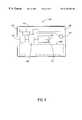
- FIG. 2is a front, side, and rear elevation view of the credit card shown in FIG. 1;
- FIG. 3is a front elevation view in schematic form of a credit card which includes an embodiment of the present invention, wherein basic components are shown;
- FIG. 4is a flow chart illustrating the operation of the credit card shown in FIG. 3;
- FIG. 5is a front elevation view in schematic form of a credit card which includes an embodiment of the present invention, wherein a solar cell senses light and light is emitted from a light emitting diode;
- FIG. 6is a flow chart illustrating the operation of the credit card shown in FIG. 5;
- FIG. 7is a front elevation view in schematic form of a credit card which includes an embodiment of the present invention, wherein a solar cell senses light and a switch is used to change messages displayed on a liquid crystal display;
- FIG. 8is a flow chart illustrating the operation of the credit card shown in FIG. 7;
- FIG. 9is a front elevation view in schematic form of a credit card which includes an embodiment of the present invention, wherein a solar cell senses light and a switch is used to toggle between two transducers; and
- FIG. 10is a flow chart illustrating the operation of the credit card shown in FIG. 9 .
- Conventional credit cardsare a well known form of identification used by individuals to have merchandise, services, etc., billed to a charge account.
- the term “credit card”, however,is intended herein to include any type of card carried by a consumer which is physically similar to a conventional credit card. Examples of such cards include debit cards, smart cards, Internet access card, prepaid calling card, electronic cash card, health insurance, association membership, and airline mileage cards. Although the term is to be understood to include all such cards, the detailed described herein below relates to conventional credit cards so as to provide a more simplified explanation of the invention. Those skilled in the art will understand that a smart card may include components that may perform some or all of the functionality of the present invention.
- the present inventionprovides a device and method for a credit card with a novel physical feature (such as those described above) to attract a consumer's attention and encourage him to open an account with a credit card issuer.
- the present inventionentices a consumer to use the credit card preferentially over other credit cards available to him at a point of purchase.
- an open wallet 12is shown to illustrate an embodiment of the disclosed invention. As is typical of many consumers' wallets, a number of credit cards 14 are positioned in close proximity to one another in pockets of wallet 12 .
- a moment of great interest to credit card issuersis when a consumer has his wallet open and is about to select a credit card to make a purchase.
- the present inventiontakes advantage of the situation by providing a device and method which distinguishes a credit card from other physically similar credit cards that are in close proximity thereto. In this way, upon opening wallet 12 , a consumer's eye is immediately drawn toward a particular credit card 10 , thereby encouraging its selection and use.
- credit card 10is shown, which conforms with the “Standards for Credit Card Specifications,” ISO 7810, of the International Organization for Standardization. As is well known, credit card 10 has a length (“L”), height (“H”), and width (“W”) of approximately 3.375, 2.127, and 0.030 inch, respectively.
- an embossing area 22is located on the lower portion of credit card 10 and has the approximate dimensions of one (1) inch by three (3) inches.
- the embossing area 22is reserved for credit card issuers to emboss a consumer's name and credit card account information.
- the Rear Viewshows a magnetic strip 24 adhered to the upper portion of credit card 10 for encoding a consumer's account information in machine readable form.
- a sensor 26is molded into the upper left-hand portion of credit card 10 .
- a transducer 28is molded into the upper portion of credit card 10 . It is convenient to position sensor 26 and transducer 28 at or near the upper edge of credit card 10 so that they are not blocked by other credit cards when the credit card is stored in wallet 12 and not thwarted from functioning as intended. Of course, the location of sensor 26 and transducer 28 are not considered critical to the present invention so long as they are capable of performing their intended respective functions as described.
- sensor 26is configured to cooperate with transducer 28 such that when sensor 26 detects a predefined physical change, it activates transducer 28 to emit a perceptible output signal.
- the physical changecan be one of a number of physical changes known in nature including, for example, a change in light intensity, pressure, or sound.
- Sensor 26can be any of a number of appropriate elements for sensing a physical change, for example, a solar cell, pressure sensor, or microphone.
- Transducer 28can be any of a number of elements for emitting perceptible output signals, for example, a light emitting diode (“LED”), liquid crystal display (“LCD”), or a speaker.
- LEDlight emitting diode
- LCDliquid crystal display
- wallet 12As an example of the above described credit card in use, consider that a consumer opens wallet 12 (FIG. 1) to select a credit card from his collection of credit cards 14 stored therein. Further, assume that sensor 26 is a solar cell and transducer 28 is an LED. When wallet 12 is opened, the solar cell detects a physical change in ambient light and activates the LED to pulse in a predetermined pattern. Because of this distinguishing feature, the consumer immediately recognizes credit card 10 and is motivated to consider whether to use it for charging a purchase.
- a sensor 102is positioned in the upper left-hand portion of credit card 100 .
- a driver circuit 104for example, a processor or a logic circuit, is positioned in the upper middle portion of credit card 100 and is in communication with sensor 102 .
- the driver circuit 104is powered by a power source 105 .
- Electrical energy supplied by the power source 105is controlled by, for example, the driver circuit, a dedicated processor or dedicated logic circuit.
- a transducer 106is positioned in the upper right-hand portion of credit card 100 and is in communication with driver circuit 104 .
- Sensor 102 , driver circuit 104 , power source 105 , and transducer 106are all located outside of an embossing area 108 .
- FIG. 4is a flow chart illustrating the operation of credit card 100 shown in FIG. 3 .
- sensor 102detects a predefined physical change and produces a signal.
- driver circuit 104receives the signal from sensor 102 and responds by producing a driver signal for a predetermined amount of time.
- the driver signal produced at step 125is transmitted to transducer 106 and a perceptible output signal is emitted in response to the driver signal.
- driver circuit 104reverts to standby mode, whereby it discontinues producing the driver signal. Consequentially, transducer 106 discontinues emitting the perceptible output signal.
- Step 135includes determining whether the predefined physical change has been detected from sensor 102 for a predetermined amount of time. For example, if the sensor 102 is a solar cell, then step 135 may include determining whether a predetermined amount of time has passed after a consumer has closed his wallet and light is discontinued from shining on the solar cell. As another example, if the sensor 102 is a pressure sensor, then step 135 may include determining whether a predetermined amount of time has passed after a consumer has closed his wallet and pressure is reapplied to the pressure sensor.
- driver circuit 104remains in standby mode. Step 135 is repeated periodically until the condition is satisfied, at which time driver circuit 104 carries out step 140 . At step 140 , driver circuit 104 is reset from standby mode to ready mode and, as a result, is ready for detecting a predefined physical change as described above in step 120 . Steps 135 and 140 are executed, for example, when a consumer closes wallet 12 (FIG. 1) after having returned credit card 100 to a pocket of wallet 12 upon completion of a purchase.
- FIG. 5there is illustrated in schematic form a credit card 200 illustrative of another embodiment of the present invention.
- a solar cell 202or another appropriate sensor, is positioned in the upper left-hand portion of credit card 200 .
- the solar cell 202senses changes in ambient light at which time it produces a signal.
- a processor 204or another appropriate processor, is positioned in the upper middle portion of credit card 200 and is in communication with solar cell 202 .
- a battery 212or another appropriate power source, provides power to processor 204 .
- Memory 210is in communication with processor 204 , thereby enabling processor 204 to retrieve instructions and store data.
- Battery 212can be one of a number of battery types, for example, a solar cell, inductive power system, radioactive cell, or thin film lithium battery.
- Memory 210can include, for example, (i) random access memory (RAM), (ii) read only memory (ROM), or (iii) a combination thereof.
- An LED 206is positioned in the upper right-hand portion of credit card 200 and is in communication with processor 204 .
- a fiber optic channel 214provides an optical path between LED 206 and the upper edge of credit card 200 .
- Each of the above elementsare located outside of an embossing area 208 .
- FIG. 6is a flow chart illustrating the operation of the credit card 200 shown in FIG. 5 .
- solar cell 202detects a change in ambient light and starts to charge battery 212 .
- the battery 212is sufficiently charged to energize processor 204 , which in turn reads and executes instructions from memory 210 .
- the instructionscause processor 204 to output a signal for a predetermined amount of time.
- LED 206emits light in response to the signal.
- the output emitted from LED 206can be a steady stream of light, short periodic pulses of light, or a pattern of light pulses.
- processor 204After the predetermined amount of time passes, processor 204 reverts to a standby mode and it discontinues producing the signal. Consequentially, LED 206 discontinues emitting light.
- Step 240includes processor 204 monitoring solar cell 202 to determine whether the change in ambient light has been removed for a predetermined amount of time. If the change in ambient light has not been removed, then processor 204 remains in standby mode. Step 240 is periodically repeated until the change in ambient light is removed, at which time processor 204 carries out step 245 . At step 245 , processor 204 is reset from standby mode to a ready mode and is ready for detecting a change in ambient light as described above in step 220 .
- FIG. 7there is illustrated in schematic form a credit card 300 which includes yet another embodiment of the present invention.
- a solar cell 302is positioned in the upper left-hand portion of credit card 300 .
- the solar cell 302is configured to sense changes in ambient light at which time it produces a signal.
- a processor 304is positioned in the upper middle portion of credit card 300 and is in communication with solar cell 302 .
- a battery 312provides power to processor 304 .
- a memory 310is in communication with processor 304 , thereby enabling the processor 304 to retrieve instructions and store data.
- Memory 310includes a first register 311 and a second register 313 .
- a switch 314is in communication with processor 304 for changing a message that may be displayed on an LCD 306 , as will be described below.
- the LCD 306is positioned in the upper right-hand portion of credit card 300 and is in communication with processor 304 .
- Each of the above elementsare located outside of an embossing area 308 .
- FIG. 8is a flow chart illustrating the operation of credit card 300 shown in FIG. 7 .
- the embodiment illustrated belowis an example of a program that can be used with credit card 300 .
- the programenables a consumer to switch between displaying a first message and a second message on LCD 306 by depressing switch 314 .
- the messagescan be displayed for a predetermined amount of time.
- solar cell 302detects a change in ambient light and produces a signal.
- processor 304receives the signal from solar cell 302 and responds by selecting a first message from memory 310 .
- the first messageis stored in first register 311 of memory 310 .
- the message to be displayedcan be selected randomly.
- the processorcan randomly select bible passages, famous quotations, or jokes that are stored in memory.
- the message to be displayedcan be selected according to the time or date.
- a real-time clock(not shown), such as an INTERSIL ICM7170, (Intersil Corp., Cupertino, Calif.) can be included to communicate with processor 304 and the messages which are selected can relate to particular dates.
- the messagesmay relate, for example, to important dates in history, holidays, paydays, or birthdays. Further, the messages can also be dynamic and/or iconic as is well known in the art. Dates may be (i) entered by a customer via an input device such as a keypad, and/or (ii) programmed into the memory when the card is manufactured.
- the first messageis transmitted to and displayed on LCD 306 for a predetermined amount of time.
- processor 304determines if switch 314 has been closed. If switch 314 has not been closed, then processor 304 advances to step 345 .
- processor 304determines whether the change in ambient light has been removed for a predetermined amount of time. If so, processor 304 advances to step 350 at which the first and a second registers, 311 and 313 , respectively, are erased and processor 304 is reset in preparation for detecting a change in ambient light with solar cell 302 .
- processor 304determines whether a second message has been stored in second register 313 of memory 310 . If a second message has not already been stored in second register 313 , then processor 304 advances to step 360 . At step 360 , processor 304 selects a second message from memory 310 . As described above, the message can be selected randomly. At step 365 , the second message is stored in second register 313 . If, at step 355 , processor 304 determines a second message has been stored in second register 313 , then processor 304 loops around steps 360 and 365 and advances to step 370 .
- the second messageis transmitted to and displayed on LCD 306 for a predetermined amount of time.
- processor 304determines whether switch 314 has been closed. If switch 314 has not been closed, then processor 304 advances to step 345 . If switch 314 has been closed, then processor 304 advances to step 335 .
- processor 304determines whether the change in ambient light has been removed for a predetermined amount of time. If so, processor 304 advances to step 350 . If the change in ambient light has not been removed, then processor 304 advances to step 380 .
- processor 304determines whether the message presently being transmitted is the first message. If the message is the first message, then processor 304 advances to step 340 . If the message is not the first message, then processor 304 advances to step 375 . Processing proceeds thereafter as described above until finally ending at step 350 .
- a credit card 400is illustrated in schematic form to depict yet another embodiment of the present invention.
- a solar cell 402is positioned in the upper left-hand portion of credit card 400 .
- the solar cell 402is configured to sense changes in ambient light at which time it produces a signal.
- a processor 404is positioned in the upper middle portion of credit card 400 and is in communication with solar cell 402 .
- a battery 412provides power to processor 404 .
- Memory 410is in communication with processor 404 , thereby enabling the processor 404 to retrieve instructions and store data.
- a switch 414is in communication with processor 404 for switching between displaying messages on an LCD 406 and emitting a light signal on LED 416 .
- the LCD 406is positioned in the upper right-hand portion of credit card 400 and is in communication with processor 404 .
- the LED 416is positioned in the left-hand portion of credit card 400 , between the solar cell 402 an the LCD 406 .
- Each of the above elementsare located outside of an embossing area 408 .
- FIG. 10is a flow chart illustrating the operation of credit card 400 shown in FIG. 9 .
- the embodiment illustrated belowis an example of a program that can be used with credit card 400 .
- the programenables a consumer to switch between displaying a message on LCD 406 and emitting a light signal on LED 416 by depressing switch 414 .
- solar cell 402detects a change in ambient light and produces a signal.
- processor 404determines whether a transducer selection is stored in a register 411 of memory 410 . If a transducer selection is not stored in register 411 , then processor 404 advances to step 430 . At step 430 , the LED 416 transducer is selected and the selection is stored in register 411 .
- processor 404selects an LED signal from memory 410 .
- the signal selected at step 435is transmitted to LED 416 for a predetermined amount of time.
- LED 416emits light in response to the selected signal.
- processor 404determines whether switch 414 has been closed. If switch 414 has not been closed, then processor 404 advances to step 450 .
- processor 404determines whether the change in ambient light has been removed for a predetermined amount of time. If so, processor 404 advances to step 455 , wherein processor 404 is reset in preparation for detecting a change in ambient light with solar cell 402 . If, at step 450 , it is determined that the change in ambient light has not been removed, then processor 404 returns to step 445 .
- processor 404determines whether the transducer selection that is stored in register 411 is for LED transducer 416 . If the selection is for LED transducer 416 , then processor 404 advances to step 435 . If the selection is for LCD transducer 406 , then processor 404 advances to step 465 .
- processor 404selects an LCD message from memory 410 .
- the message selected at step 465is transmitted to LCD 406 for a predetermined amount of time.
- LCD 406displays the message in response to receiving the selected message and processor 404 advances to step 445 .
- processor 404determines whether switch 414 has been closed. If switch 414 has not been closed, then processor 404 advances to step 450 . If switch 414 has been closed, then processor 404 advances to step 475 . At step 475 , the transducer selection previously stored in register 411 is replaced with the other transducer selection. That is, if LED transducer 416 was previously selected as the active transducer, then processor 404 would now select the LCD transducer 406 as the active transducer and store this selection in register 411 , and visa versa. Processing proceeds thereafter as described above until finally ending at step 455 .
- a credit card including the basic embodiment of the present invention as described above and illustrated in FIG. 3can utilize a speaker, such as a piezoelectric vibrator, as a transducer for emitting sound stored in machine readable form in a memory.
- the speakercan emit a sound, e.g., a chirping sound, when a consumer opens his wallet.
- a variation of this embodimentincludes utilizing magnetic strip 24 (FIG. 2) as a sensor and configuring the device to emit a sound when the credit card is passed through a credit card reader.
- a credit card including the basic embodiment of the present invention as described above and illustrated in FIG. 3can utilize a pressure sensor that detects when a wallet has been opened.
- the sensordetects that the pressure has been removed, it activates, for example, an LCD, LED, or speaker.
- the present device and method for promoting the selection and use of a credit cardprovides an advancement in the art.
- the device and methodprovides a credit card issuer a variety of ways in which they can make credit cards distinguishable from other credit cards.
Landscapes
- Engineering & Computer Science (AREA)
- Business, Economics & Management (AREA)
- Physics & Mathematics (AREA)
- Accounting & Taxation (AREA)
- Development Economics (AREA)
- Finance (AREA)
- General Physics & Mathematics (AREA)
- Strategic Management (AREA)
- Entrepreneurship & Innovation (AREA)
- Marketing (AREA)
- Economics (AREA)
- General Business, Economics & Management (AREA)
- Game Theory and Decision Science (AREA)
- Theoretical Computer Science (AREA)
- Computer Security & Cryptography (AREA)
- Credit Cards Or The Like (AREA)
- Control Of Vending Devices And Auxiliary Devices For Vending Devices (AREA)
Abstract
Description
Claims (120)
Priority Applications (8)
| Application Number | Priority Date | Filing Date | Title |
|---|---|---|---|
| US09/223,164US6325284B1 (en) | 1998-12-30 | 1998-12-30 | Device and method for promoting the selection and use of a credit card |
| PCT/US1999/029658WO2000041111A2 (en) | 1998-12-30 | 1999-12-14 | Device and method for promoting the selection and use of a credit card |
| AU21822/00AAU2182200A (en) | 1998-12-30 | 1999-12-14 | Device and method for promoting the selection and use of a credit card |
| US10/146,302US6739505B2 (en) | 1998-12-30 | 2001-10-26 | Device and method for promoting the selection and use of a transaction card |
| US10/849,622US7090123B2 (en) | 1998-12-30 | 2004-05-19 | Method and apparatus for promoting the selection and use of a transaction card |
| US11/459,063US7806320B2 (en) | 1998-12-30 | 2006-07-21 | Method and apparatus for promoting the selection and use of a transaction card |
| US12/898,273US7988044B2 (en) | 1998-12-30 | 2010-10-05 | Method and apparatus for promoting the selection and use of a transaction card |
| US13/196,350US8632005B2 (en) | 1998-12-30 | 2011-08-02 | Method and apparatus for promoting the selection and use of a transaction card |
Applications Claiming Priority (1)
| Application Number | Priority Date | Filing Date | Title |
|---|---|---|---|
| US09/223,164US6325284B1 (en) | 1998-12-30 | 1998-12-30 | Device and method for promoting the selection and use of a credit card |
Related Child Applications (1)
| Application Number | Title | Priority Date | Filing Date |
|---|---|---|---|
| US10/146,302Continuation-In-PartUS6739505B2 (en) | 1998-12-30 | 2001-10-26 | Device and method for promoting the selection and use of a transaction card |
Publications (1)
| Publication Number | Publication Date |
|---|---|
| US6325284B1true US6325284B1 (en) | 2001-12-04 |
Family
ID=22835325
Family Applications (2)
| Application Number | Title | Priority Date | Filing Date |
|---|---|---|---|
| US09/223,164Expired - LifetimeUS6325284B1 (en) | 1998-12-30 | 1998-12-30 | Device and method for promoting the selection and use of a credit card |
| US10/146,302Expired - Fee RelatedUS6739505B2 (en) | 1998-12-30 | 2001-10-26 | Device and method for promoting the selection and use of a transaction card |
Family Applications After (1)
| Application Number | Title | Priority Date | Filing Date |
|---|---|---|---|
| US10/146,302Expired - Fee RelatedUS6739505B2 (en) | 1998-12-30 | 2001-10-26 | Device and method for promoting the selection and use of a transaction card |
Country Status (3)
| Country | Link |
|---|---|
| US (2) | US6325284B1 (en) |
| AU (1) | AU2182200A (en) |
| WO (1) | WO2000041111A2 (en) |
Cited By (23)
| Publication number | Priority date | Publication date | Assignee | Title |
|---|---|---|---|---|
| WO2002059724A3 (en)* | 2001-01-25 | 2002-10-10 | David Sidman | Apparatus, method and system for tracking information access |
| US20030081275A1 (en)* | 2001-10-26 | 2003-05-01 | Kazuo Shishido | Structure for preventing extraneous light from entering image reading apparatus |
| US6601761B1 (en)* | 1998-09-15 | 2003-08-05 | Citibank, N.A. | Method and system for co-branding an electronic payment platform such as an electronic wallet |
| US20030222152A1 (en)* | 2002-05-28 | 2003-12-04 | Boley George E.S. | Pre-paid debit & credit card |
| US20030226899A1 (en)* | 2002-06-11 | 2003-12-11 | Lenscard U.S., Llc | Method for making a financial transaction card with embedded electronic circuitry |
| US20040026506A1 (en)* | 2002-08-06 | 2004-02-12 | Alan Finkelstein | Financial transaction card with sound recording |
| US20040026495A1 (en)* | 2002-08-06 | 2004-02-12 | Alan Finkelstein | Transaction card with annunciator |
| US20040088333A1 (en)* | 2002-01-25 | 2004-05-06 | David Sidman | Apparatus method and system for tracking information access |
| US6769618B1 (en)* | 1992-02-12 | 2004-08-03 | Lenscard U.S., Llc | Wallet card with a magnifying lens and light |
| US6813716B1 (en)* | 2000-04-24 | 2004-11-02 | At&T Corp. | Secure calling card and authentication process |
| US20040226995A1 (en)* | 2003-05-16 | 2004-11-18 | American Express Travel Related Services Company, Inc. | System and method for facilitating a transaction between a merchant and a consumer |
| US20040238625A1 (en)* | 1998-12-30 | 2004-12-02 | Walker Jay S. | Method and apparatus for promoting the selection and use of a transaction card |
| US20050122216A1 (en)* | 2003-12-08 | 2005-06-09 | Matz William R. | Key for lock |
| US7249715B1 (en)* | 2002-01-11 | 2007-07-31 | Bradley Leonard Lambright | Key ring card wallet |
| US20090037411A1 (en)* | 2007-07-31 | 2009-02-05 | Vaibhava Goel | Membership selection assistant |
| US20090206151A1 (en)* | 2005-02-24 | 2009-08-20 | Kyocera Corporation | Reader Device and Outing Data Carrier Decision Method |
| US20100088168A1 (en)* | 2008-10-03 | 2010-04-08 | Target Brands, Inc. | Account application product, associated package and method for processing an associated application |
| USD622587S1 (en) | 2008-10-03 | 2010-08-31 | Target Brands, Inc. | Retail package |
| US20110313830A1 (en)* | 2006-12-29 | 2011-12-22 | American Express Travel Related Services Company, Inc. | System and method for targeting transaction account product holders to receive upgraded transaction account products |
| US10243088B1 (en)* | 2017-12-21 | 2019-03-26 | Capital One Services, Llc | Transaction card for transferring solar power |
| US11055700B1 (en) | 2020-04-30 | 2021-07-06 | Capital One Services, Llc | Payment card with user feedback |
| US11263918B1 (en)* | 2014-07-14 | 2022-03-01 | Guangtian Liu | Audio bible players with a numerical indexing system and a multiple bible version playback function |
| US20230252258A1 (en)* | 2022-02-09 | 2023-08-10 | Stmicroelectronics (Rousset) Sas | Contactless communication device |
Families Citing this family (18)
| Publication number | Priority date | Publication date | Assignee | Title |
|---|---|---|---|---|
| US7682245B2 (en)* | 2000-02-29 | 2010-03-23 | Igt | Name your prize game playing methodology |
| US7013365B2 (en)* | 2003-06-16 | 2006-03-14 | Michael Arnouse | System of secure personal identification, information processing, and precise point of contact location and timing |
| JP2005261765A (en)* | 2004-03-19 | 2005-09-29 | Aruze Corp | Medal reception device |
| US20050242170A1 (en)* | 2004-05-01 | 2005-11-03 | Epana Networks, Inc. | Prepaid long-distance telephone calling card with separable coupon |
| USD534913S1 (en)* | 2004-08-25 | 2007-01-09 | Bud Wilcox | Interactive display card |
| US7481365B2 (en)* | 2006-07-05 | 2009-01-27 | International Business Machines Corporation | System and method for transaction card electronic messaging |
| US20080076528A1 (en)* | 2006-09-08 | 2008-03-27 | Igt | Instant anonymous account creation |
| GB0618266D0 (en)* | 2006-09-18 | 2006-10-25 | Dosanjh Harkamaljit | Mobile devices and systems for using them |
| US8181879B2 (en) | 2006-12-29 | 2012-05-22 | Solicore, Inc. | Mailing apparatus for powered cards |
| WO2008082616A1 (en) | 2006-12-29 | 2008-07-10 | Solicore, Inc. | Card configured to receive separate battery |
| US20100042236A1 (en)* | 2008-08-15 | 2010-02-18 | Ncr Corporation | Self-service terminal |
| US9010646B2 (en)* | 2010-04-01 | 2015-04-21 | Coin, Inc. | Optical contact loaded magnetic card |
| US8998096B2 (en) | 2010-04-01 | 2015-04-07 | Coin, Inc. | Magnetic emissive use of preloaded payment card account numbers |
| US8384690B2 (en) | 2010-05-14 | 2013-02-26 | International Business Machines Corp. | Interface device with integrated solar cell(S) for power collection |
| US20110295691A1 (en)* | 2010-05-27 | 2011-12-01 | Krieter Marcus | Radio receiver based greeting card system |
| US9165295B2 (en) | 2011-05-09 | 2015-10-20 | Moon J. Kim | Automated card information exchange pursuant to a commercial transaction |
| US8490872B2 (en)* | 2011-06-15 | 2013-07-23 | Moon J. Kim | Light-powered smart card for on-line transaction processing |
| US20140195325A1 (en)* | 2013-01-07 | 2014-07-10 | Pietro G. Denevi | Credit card and service organization cooperative program |
Citations (26)
| Publication number | Priority date | Publication date | Assignee | Title |
|---|---|---|---|---|
| US4443027A (en) | 1981-07-29 | 1984-04-17 | Mcneely Maurice G | Multiple company credit card system |
| US4614144A (en) | 1983-09-28 | 1986-09-30 | Oki Electric Industry Co., Ltd. | Music card system |
| US4648189A (en) | 1985-01-18 | 1987-03-10 | Data Medi-Card, Inc. | Laminated medical data card |
| US4667088A (en) | 1981-11-02 | 1987-05-19 | Kramer Kane N | Portable data processing and storage system |
| US4677657A (en)* | 1984-07-31 | 1987-06-30 | Omron Tateisi Electronics Co. | Voice recording card |
| US4692745A (en) | 1985-12-23 | 1987-09-08 | Solly Simanowitz | Credit card alarm |
| US4851654A (en)* | 1987-05-30 | 1989-07-25 | Kabushiki Kaisha Toshiba | IC card |
| FR2629613A1 (en) | 1988-03-29 | 1989-10-06 | Kuehn Daniel | Warning device for preventing the loss of a coded card, especially of a credit card |
| US4916296A (en) | 1987-10-29 | 1990-04-10 | Jerry R. Iggulden | Light modulating smart card |
| US5056145A (en) | 1987-06-03 | 1991-10-08 | Kabushiki Kaisha Toshiba | Digital sound data storing device |
| US5140517A (en)* | 1984-03-19 | 1992-08-18 | Omron Tateisi Electronics Co. | IC card with keyboard for prestoring transaction data |
| US5192947A (en) | 1990-02-02 | 1993-03-09 | Simon Neustein | Credit card pager apparatus |
| US5204657A (en) | 1991-05-28 | 1993-04-20 | Impact Products Corporation | Locating device |
| US5234729A (en) | 1992-02-27 | 1993-08-10 | The Dow Chemical Company | Multilayer polymeric reflective bodies for decorative and security applications |
| US5359183A (en) | 1992-04-06 | 1994-10-25 | Rafael Skodlar | Payment card with display |
| US5412192A (en) | 1993-07-20 | 1995-05-02 | American Express Company | Radio frequency activated charge card |
| US5418520A (en) | 1991-11-10 | 1995-05-23 | Hirshberg; Israel | Credit card alert system |
| US5515031A (en) | 1994-03-28 | 1996-05-07 | Pereira; Neil H. | Credit card detector and validator |
| US5548271A (en) | 1993-06-28 | 1996-08-20 | Nec Corporation | Data display radio pager |
| US5585787A (en) | 1991-12-09 | 1996-12-17 | Wallerstein; Robert S. | Programmable credit card |
| US5642095A (en) | 1995-10-18 | 1997-06-24 | Wellesley Research Associates, Inc. | Alarm for a card shaped object |
| EP0785527A2 (en) | 1996-01-22 | 1997-07-23 | Motorola, Inc. | Solar cell powered smart card with integrated display and interface |
| US5675627A (en) | 1994-11-29 | 1997-10-07 | Lucent Technologies Inc. | Integrated pager and calling card |
| US5679939A (en) | 1994-07-11 | 1997-10-21 | Nec Corporation | IC card for outputting notification of a transaction by voice |
| US5746451A (en) | 1995-09-05 | 1998-05-05 | Weyer; Frank M. | Customizable credit card overlay |
| WO1998024071A1 (en) | 1996-11-25 | 1998-06-04 | Security Signs & Service As | Security and alarm device for keys/key cards |
Family Cites Families (8)
| Publication number | Priority date | Publication date | Assignee | Title |
|---|---|---|---|---|
| US592745A (en)* | 1897-10-26 | James samuel foley | ||
| DE3426601C2 (en)* | 1984-07-19 | 1986-12-11 | PUMA AG Rudolf Dassler Sport, 8522 Herzogenaurach | Sports shoe |
| US4667657A (en)* | 1985-10-22 | 1987-05-26 | Institut Blagoveschensky Gosudarstvenny Meditsinsky | Surgical wound retractor |
| US4804825A (en)* | 1986-06-17 | 1989-02-14 | Casio Computer Co., Ltd. | I C card system |
| US5120939A (en)* | 1989-11-09 | 1992-06-09 | At&T Bell Laboratories | Databaseless security system |
| US5955961A (en)* | 1991-12-09 | 1999-09-21 | Wallerstein; Robert S. | Programmable transaction card |
| US5857079A (en)* | 1994-12-23 | 1999-01-05 | Lucent Technologies Inc. | Smart card for automatic financial records |
| KR100213098B1 (en)* | 1997-03-14 | 1999-08-02 | 윤종용 | Electronic money terminal function and performing method |
- 1998
- 1998-12-30USUS09/223,164patent/US6325284B1/ennot_activeExpired - Lifetime
- 1999
- 1999-12-14WOPCT/US1999/029658patent/WO2000041111A2/enactiveApplication Filing
- 1999-12-14AUAU21822/00Apatent/AU2182200A/ennot_activeAbandoned
- 2001
- 2001-10-26USUS10/146,302patent/US6739505B2/ennot_activeExpired - Fee Related
Patent Citations (26)
| Publication number | Priority date | Publication date | Assignee | Title |
|---|---|---|---|---|
| US4443027A (en) | 1981-07-29 | 1984-04-17 | Mcneely Maurice G | Multiple company credit card system |
| US4667088A (en) | 1981-11-02 | 1987-05-19 | Kramer Kane N | Portable data processing and storage system |
| US4614144A (en) | 1983-09-28 | 1986-09-30 | Oki Electric Industry Co., Ltd. | Music card system |
| US5140517A (en)* | 1984-03-19 | 1992-08-18 | Omron Tateisi Electronics Co. | IC card with keyboard for prestoring transaction data |
| US4677657A (en)* | 1984-07-31 | 1987-06-30 | Omron Tateisi Electronics Co. | Voice recording card |
| US4648189A (en) | 1985-01-18 | 1987-03-10 | Data Medi-Card, Inc. | Laminated medical data card |
| US4692745A (en) | 1985-12-23 | 1987-09-08 | Solly Simanowitz | Credit card alarm |
| US4851654A (en)* | 1987-05-30 | 1989-07-25 | Kabushiki Kaisha Toshiba | IC card |
| US5056145A (en) | 1987-06-03 | 1991-10-08 | Kabushiki Kaisha Toshiba | Digital sound data storing device |
| US4916296A (en) | 1987-10-29 | 1990-04-10 | Jerry R. Iggulden | Light modulating smart card |
| FR2629613A1 (en) | 1988-03-29 | 1989-10-06 | Kuehn Daniel | Warning device for preventing the loss of a coded card, especially of a credit card |
| US5192947A (en) | 1990-02-02 | 1993-03-09 | Simon Neustein | Credit card pager apparatus |
| US5204657A (en) | 1991-05-28 | 1993-04-20 | Impact Products Corporation | Locating device |
| US5418520A (en) | 1991-11-10 | 1995-05-23 | Hirshberg; Israel | Credit card alert system |
| US5585787A (en) | 1991-12-09 | 1996-12-17 | Wallerstein; Robert S. | Programmable credit card |
| US5234729A (en) | 1992-02-27 | 1993-08-10 | The Dow Chemical Company | Multilayer polymeric reflective bodies for decorative and security applications |
| US5359183A (en) | 1992-04-06 | 1994-10-25 | Rafael Skodlar | Payment card with display |
| US5548271A (en) | 1993-06-28 | 1996-08-20 | Nec Corporation | Data display radio pager |
| US5412192A (en) | 1993-07-20 | 1995-05-02 | American Express Company | Radio frequency activated charge card |
| US5515031A (en) | 1994-03-28 | 1996-05-07 | Pereira; Neil H. | Credit card detector and validator |
| US5679939A (en) | 1994-07-11 | 1997-10-21 | Nec Corporation | IC card for outputting notification of a transaction by voice |
| US5675627A (en) | 1994-11-29 | 1997-10-07 | Lucent Technologies Inc. | Integrated pager and calling card |
| US5746451A (en) | 1995-09-05 | 1998-05-05 | Weyer; Frank M. | Customizable credit card overlay |
| US5642095A (en) | 1995-10-18 | 1997-06-24 | Wellesley Research Associates, Inc. | Alarm for a card shaped object |
| EP0785527A2 (en) | 1996-01-22 | 1997-07-23 | Motorola, Inc. | Solar cell powered smart card with integrated display and interface |
| WO1998024071A1 (en) | 1996-11-25 | 1998-06-04 | Security Signs & Service As | Security and alarm device for keys/key cards |
Non-Patent Citations (3)
| Title |
|---|
| Abstract: "These Batteries are Ultra-Thin", Oak Ridge National Laboratory R&D Journal, Sep. 1996 at p. 66. |
| Lisa Fickenscher, "Chase Lens Card Magnifies Its Bid to be Picked For Use", American Banker, Aug. 13, 1998 at p. 20. |
| Satoshi Ohta et al., "Packaging Technology for Smart IC Cards with a Display Element", OKI Technical Review, Jun. 1991 at p. 49. |
Cited By (41)
| Publication number | Priority date | Publication date | Assignee | Title |
|---|---|---|---|---|
| US6769618B1 (en)* | 1992-02-12 | 2004-08-03 | Lenscard U.S., Llc | Wallet card with a magnifying lens and light |
| US6817532B2 (en) | 1992-02-12 | 2004-11-16 | Lenscard U.S., Llc | Wallet card with built-in light |
| US6601761B1 (en)* | 1998-09-15 | 2003-08-05 | Citibank, N.A. | Method and system for co-branding an electronic payment platform such as an electronic wallet |
| US20040238625A1 (en)* | 1998-12-30 | 2004-12-02 | Walker Jay S. | Method and apparatus for promoting the selection and use of a transaction card |
| US7988044B2 (en) | 1998-12-30 | 2011-08-02 | Walker Digital, Llc | Method and apparatus for promoting the selection and use of a transaction card |
| US7806320B2 (en) | 1998-12-30 | 2010-10-05 | Walker Digital, Llc | Method and apparatus for promoting the selection and use of a transaction card |
| US7090123B2 (en) | 1998-12-30 | 2006-08-15 | Walker Digital, Llc | Method and apparatus for promoting the selection and use of a transaction card |
| US8632005B2 (en) | 1998-12-30 | 2014-01-21 | Inventor Holdings, Llc | Method and apparatus for promoting the selection and use of a transaction card |
| US6813716B1 (en)* | 2000-04-24 | 2004-11-02 | At&T Corp. | Secure calling card and authentication process |
| WO2002059724A3 (en)* | 2001-01-25 | 2002-10-10 | David Sidman | Apparatus, method and system for tracking information access |
| US8156151B2 (en) | 2001-01-25 | 2012-04-10 | Content Directions, Inc. | Apparatus, method and system for tracking information access |
| US20100211552A1 (en)* | 2001-01-25 | 2010-08-19 | Content Directions, Inc. | Apparatus, Method and System for Tracking Information Access |
| US20030081275A1 (en)* | 2001-10-26 | 2003-05-01 | Kazuo Shishido | Structure for preventing extraneous light from entering image reading apparatus |
| US7249715B1 (en)* | 2002-01-11 | 2007-07-31 | Bradley Leonard Lambright | Key ring card wallet |
| US20040088333A1 (en)* | 2002-01-25 | 2004-05-06 | David Sidman | Apparatus method and system for tracking information access |
| US20030222152A1 (en)* | 2002-05-28 | 2003-12-04 | Boley George E.S. | Pre-paid debit & credit card |
| US6902116B2 (en) | 2002-06-11 | 2005-06-07 | Innovative Card Technologies, Inc. | Method for making a financial transaction card with embedded electronic circuitry |
| US20030226899A1 (en)* | 2002-06-11 | 2003-12-11 | Lenscard U.S., Llc | Method for making a financial transaction card with embedded electronic circuitry |
| US7225994B2 (en)* | 2002-08-06 | 2007-06-05 | Innovative Card Technologies, Inc. | Financial transaction card with sound recording |
| US20040026495A1 (en)* | 2002-08-06 | 2004-02-12 | Alan Finkelstein | Transaction card with annunciator |
| US20040026506A1 (en)* | 2002-08-06 | 2004-02-12 | Alan Finkelstein | Financial transaction card with sound recording |
| US6988658B2 (en)* | 2003-05-16 | 2006-01-24 | American Express Travel Related Services Company, Inc. | System and method for facilitating a transaction between a merchant and a consumer |
| US20040226995A1 (en)* | 2003-05-16 | 2004-11-18 | American Express Travel Related Services Company, Inc. | System and method for facilitating a transaction between a merchant and a consumer |
| US20050122216A1 (en)* | 2003-12-08 | 2005-06-09 | Matz William R. | Key for lock |
| US20090206151A1 (en)* | 2005-02-24 | 2009-08-20 | Kyocera Corporation | Reader Device and Outing Data Carrier Decision Method |
| US8567683B2 (en)* | 2005-02-24 | 2013-10-29 | Kyocera Corporation | Reader device and outing data carrier decision method |
| US20110313830A1 (en)* | 2006-12-29 | 2011-12-22 | American Express Travel Related Services Company, Inc. | System and method for targeting transaction account product holders to receive upgraded transaction account products |
| US8688503B2 (en) | 2006-12-29 | 2014-04-01 | American Express Travel Related Services Company, Inc. | System and method for targeting family members of transaction account product holders to receive supplementary transaction account products |
| US8229784B2 (en)* | 2006-12-29 | 2012-07-24 | American Express Travel Related Services Company, Inc. | System and method for targeting transaction account product holders to receive upgraded transaction account products |
| US20090037411A1 (en)* | 2007-07-31 | 2009-02-05 | Vaibhava Goel | Membership selection assistant |
| US8322619B2 (en) | 2008-10-03 | 2012-12-04 | Target Brands, Inc. | Account application product, associated package and method for processing an associated application |
| USD622587S1 (en) | 2008-10-03 | 2010-08-31 | Target Brands, Inc. | Retail package |
| US8657197B2 (en) | 2008-10-03 | 2014-02-25 | Target Brands, Inc. | Account application product, associated package and method for processing an associated application |
| US20100088168A1 (en)* | 2008-10-03 | 2010-04-08 | Target Brands, Inc. | Account application product, associated package and method for processing an associated application |
| US11263918B1 (en)* | 2014-07-14 | 2022-03-01 | Guangtian Liu | Audio bible players with a numerical indexing system and a multiple bible version playback function |
| US10243088B1 (en)* | 2017-12-21 | 2019-03-26 | Capital One Services, Llc | Transaction card for transferring solar power |
| US10930801B2 (en) | 2017-12-21 | 2021-02-23 | Capital One Services, Llc | Transaction card for transferring solar power |
| US11055700B1 (en) | 2020-04-30 | 2021-07-06 | Capital One Services, Llc | Payment card with user feedback |
| US11410158B2 (en) | 2020-04-30 | 2022-08-09 | Capital One Services, Llc | Payment card with user feedback |
| US20230252258A1 (en)* | 2022-02-09 | 2023-08-10 | Stmicroelectronics (Rousset) Sas | Contactless communication device |
| US12079679B2 (en)* | 2022-02-09 | 2024-09-03 | Stmicroelectronics (Rousset) Sas | Contactless communication device |
Also Published As
| Publication number | Publication date |
|---|---|
| WO2000041111A2 (en) | 2000-07-13 |
| US20020190121A1 (en) | 2002-12-19 |
| US6739505B2 (en) | 2004-05-25 |
| AU2182200A (en) | 2000-07-24 |
| WO2000041111A3 (en) | 2001-03-08 |
Similar Documents
| Publication | Publication Date | Title |
|---|---|---|
| US6325284B1 (en) | Device and method for promoting the selection and use of a credit card | |
| US7806320B2 (en) | Method and apparatus for promoting the selection and use of a transaction card | |
| US7871013B2 (en) | Transaction product with electrical circuit | |
| US6024288A (en) | Promotion system including an ic-card memory for obtaining and tracking a plurality of transactions | |
| US7661588B2 (en) | Stored-value card with pedometer and clip | |
| US7815108B2 (en) | Transaction product with electrical circuit | |
| US7866550B2 (en) | Transaction card with sound and transformative playback feature | |
| US6572020B2 (en) | Retail sales cutomer auto-ID activation | |
| WO1998029829A9 (en) | Real-time individually-targeted promotions | |
| US8647203B2 (en) | Transaction product with selectively illuminated buttons | |
| CN101916412A (en) | Electronic shelf label and display method thereof | |
| US7784686B2 (en) | Transaction card with enclosed chamber | |
| RU2000126391A (en) | TRADING MACHINE WITH ADVERTISING FUNCTION AND METHOD FOR MANAGING THEM | |
| GB2451576A (en) | Separable card assembly | |
| JPH04136778U (en) | Information display device for card-type vending machines | |
| MXPA99006056A (en) | Method and apparatus for real-time, individually-targeted promotions | |
| Denlertchaikul | The feasibility study of loyalty card for hypermarket in Bangkok: Carrefour case study | |
| JP2003030693A (en) | Point card system and gate device |
Legal Events
| Date | Code | Title | Description |
|---|---|---|---|
| AS | Assignment | Owner name:WALKER DIGITAL CORPORATION, CONNECTICUT Free format text:ASSIGNMENT OF ASSIGNORS INTEREST;ASSIGNORS:WALKER, JAY S.;SCHNEIER, BRUCE;MIK, MAGDALENA;REEL/FRAME:009769/0812 Effective date:19990208 | |
| AS | Assignment | Owner name:WALKER DIGITAL, LLC., CONNECTICUT Free format text:ASSIGNMENT OF ASSIGNORS INTEREST;ASSIGNOR:WALKER DIGITAL CORPORATION;REEL/FRAME:010648/0653 Effective date:19991130 Owner name:WALKER DIGITAL, LLC.,CONNECTICUT Free format text:ASSIGNMENT OF ASSIGNORS INTEREST;ASSIGNOR:WALKER DIGITAL CORPORATION;REEL/FRAME:010648/0653 Effective date:19991130 | |
| AS | Assignment | Owner name:JAY WALKER, CONNECTICUT Free format text:SECURITY AGREEMENT;ASSIGNOR:WALKER DIGITAL, LLC;REEL/FRAME:011277/0178 Effective date:20001201 Owner name:JAY WALKER,CONNECTICUT Free format text:SECURITY AGREEMENT;ASSIGNOR:WALKER DIGITAL, LLC;REEL/FRAME:011277/0178 Effective date:20001201 | |
| AS | Assignment | Owner name:GAP-WD HOLDINGS, INC., CONNECTICUT Free format text:SECURITY INTEREST;ASSIGNOR:WALKER DIGITAL, LLC.;REEL/FRAME:011399/0501 Effective date:20001208 Owner name:GAP-WD HOLDINGS, INC.,CONNECTICUT Free format text:SECURITY INTEREST;ASSIGNOR:WALKER DIGITAL, LLC.;REEL/FRAME:011399/0501 Effective date:20001208 | |
| AS | Assignment | Owner name:WALKER, JAY, CONNECTICUT Free format text:SECURITY INTEREST;ASSIGNOR:WALKER DIGITAL, LLC;REEL/FRAME:011874/0792 Effective date:20010531 Owner name:WALKER, JAY,CONNECTICUT Free format text:SECURITY INTEREST;ASSIGNOR:WALKER DIGITAL, LLC;REEL/FRAME:011874/0792 Effective date:20010531 | |
| STCF | Information on status: patent grant | Free format text:PATENTED CASE | |
| AS | Assignment | Owner name:JSW INVESTMENTS, LLC, CONNECTICUT Free format text:SECURITY INTEREST;ASSIGNOR:WALKER DIGITAL, LLC;REEL/FRAME:013740/0219 Effective date:20021226 | |
| FPAY | Fee payment | Year of fee payment:4 | |
| AS | Assignment | Owner name:WALKER DIGITAL, LLC, CONNECTICUT Free format text:RELEASE BY SECURED PARTY;ASSIGNOR:JSW INVESTMENTS, LLC;REEL/FRAME:017783/0080 Effective date:20050527 | |
| AS | Assignment | Owner name:WALKER DIGITAL, LLC, CONNECTICUT Free format text:RELEASE OF SECURITY INTEREST;ASSIGNOR:JSW INVESTMENTS, LLC;REEL/FRAME:018668/0615 Effective date:20050527 | |
| AS | Assignment | Owner name:WALKER DIGITAL, LLC, CONNECTICUT Free format text:RELEASE OF LIEN;ASSIGNOR:GAP-WD HOLDINGS, INC.;REEL/FRAME:017073/0445 Effective date:20060125 Owner name:WALKER DIGITAL, LLC, CONNECTICUT Free format text:RELEASE OF LIEN;ASSIGNOR:WALKER, JAY;REEL/FRAME:017073/0477 Effective date:20060125 | |
| FEPP | Fee payment procedure | Free format text:PAT HOLDER NO LONGER CLAIMS SMALL ENTITY STATUS, ENTITY STATUS SET TO UNDISCOUNTED (ORIGINAL EVENT CODE: STOL); ENTITY STATUS OF PATENT OWNER: LARGE ENTITY | |
| FPAY | Fee payment | Year of fee payment:8 | |
| FPAY | Fee payment | Year of fee payment:12 | |
| AS | Assignment | Owner name:IGT, NEVADA Free format text:LICENSE;ASSIGNORS:WALKER DIGITAL GAMING, LLC;WALKER DIGITAL GAMING HOLDING, LLC;WDG EQUITY, LLC;AND OTHERS;REEL/FRAME:033501/0023 Effective date:20090810 | |
| AS | Assignment | Owner name:INVENTOR HOLDINGS, LLC, CONNECTICUT Free format text:ASSIGNMENT OF ASSIGNORS INTEREST;ASSIGNOR:WALKER DIGITAL, LLC;REEL/FRAME:034856/0855 Effective date:20131101 |