US6321888B1 - Damper with externally mounted semi-active system - Google Patents
Damper with externally mounted semi-active systemDownload PDFInfo
- Publication number
- US6321888B1 US6321888B1US09/318,301US31830199AUS6321888B1US 6321888 B1US6321888 B1US 6321888B1US 31830199 AUS31830199 AUS 31830199AUS 6321888 B1US6321888 B1US 6321888B1
- Authority
- US
- United States
- Prior art keywords
- rebound
- compression
- damper
- fluid
- reservoir
- Prior art date
- Legal status (The legal status is an assumption and is not a legal conclusion. Google has not performed a legal analysis and makes no representation as to the accuracy of the status listed.)
- Expired - Lifetime
Links
Images


Classifications
- F—MECHANICAL ENGINEERING; LIGHTING; HEATING; WEAPONS; BLASTING
- F16—ENGINEERING ELEMENTS AND UNITS; GENERAL MEASURES FOR PRODUCING AND MAINTAINING EFFECTIVE FUNCTIONING OF MACHINES OR INSTALLATIONS; THERMAL INSULATION IN GENERAL
- F16F—SPRINGS; SHOCK-ABSORBERS; MEANS FOR DAMPING VIBRATION
- F16F9/00—Springs, vibration-dampers, shock-absorbers, or similarly-constructed movement-dampers using a fluid or the equivalent as damping medium
- F16F9/32—Details
- F16F9/3207—Constructional features
- F16F9/3235—Constructional features of cylinders
- F16F9/325—Constructional features of cylinders for attachment of valve units
- F—MECHANICAL ENGINEERING; LIGHTING; HEATING; WEAPONS; BLASTING
- F16—ENGINEERING ELEMENTS AND UNITS; GENERAL MEASURES FOR PRODUCING AND MAINTAINING EFFECTIVE FUNCTIONING OF MACHINES OR INSTALLATIONS; THERMAL INSULATION IN GENERAL
- F16F—SPRINGS; SHOCK-ABSORBERS; MEANS FOR DAMPING VIBRATION
- F16F9/00—Springs, vibration-dampers, shock-absorbers, or similarly-constructed movement-dampers using a fluid or the equivalent as damping medium
- F16F9/32—Details
- F16F9/44—Means on or in the damper for manual or non-automatic adjustment; such means combined with temperature correction
- F16F9/46—Means on or in the damper for manual or non-automatic adjustment; such means combined with temperature correction allowing control from a distance, i.e. location of means for control input being remote from site of valves, e.g. on damper external wall
- F16F9/466—Throttling control, i.e. regulation of flow passage geometry
- B—PERFORMING OPERATIONS; TRANSPORTING
- B60—VEHICLES IN GENERAL
- B60G—VEHICLE SUSPENSION ARRANGEMENTS
- B60G2202/00—Indexing codes relating to the type of spring, damper or actuator
- B60G2202/30—Spring/Damper and/or actuator Units
- B60G2202/31—Spring/Damper and/or actuator Units with the spring arranged around the damper, e.g. MacPherson strut
- B60G2202/312—The spring being a wound spring
- B—PERFORMING OPERATIONS; TRANSPORTING
- B60—VEHICLES IN GENERAL
- B60G—VEHICLE SUSPENSION ARRANGEMENTS
- B60G2500/00—Indexing codes relating to the regulated action or device
- B60G2500/10—Damping action or damper
- B60G2500/11—Damping valves
Definitions
- This inventionrelates generally to hydraulic dampers, and more particularly to a new and improved semi-active damper with an externally mounted valve assembly for selectively varying stiffness of the damper in compression and separately selectively varying stiffness of the damper in rebound.
- Dampersare used in conjunction with automotive suspension systems to absorb unwanted vibrations which occur while driving a vehicle.
- dampersare generally connected between the body and the suspension of an automobile.
- a pistonis located within the damper which is connected to the body of the automobile through a piston rod.
- the damper bodyis connected to the suspension of the automobile. Because the piston is able to limit the flow of damping fluid within the working chamber of the damper as the damper is compressed extended, the damper is able to produce a damping force which counteracts suspension system vibration which wold otherwise be transmitted from the suspension to the body. By further restricting the flow of damping fluid within the working chamber of a damper, greater damping forces are generated by the damper.
- ride comfortis typically a function of the spring constant of the vehicle's main springs, as well as the spring constant of the occupant's seat, the vehicle's tires the suspension geometry, and the damper.
- Vehicle handlingis related to changes in the vehicle's attitude (i.e., pitch, yaw, and roll). To achieve optimum vehicle handling, relatively large damping forces are required to avoid excessively rapid variation in the vehicle's attitude during acceleration, deceleration, and cornering.
- Road holding abilityis generally dependent on the amount of contact between the vehicle tires and the ground. In order to optimize a vehicle's road holding ability, large damping forces are required as a vehicle passes over irregular surfaces in order to prevent loss of contact between the wheels and ground for an excessive period of time.
- dampers which provide adjustable dampinggenerally use a single valve to control the flow of damping fluid during both compression and rebound, a sensor is generally required to determine whether the damper is in compression or rebound. Not only does this provide a degree of difficultly in terms of sensor placement, there are also disadvantages with respect to the electronics which are required to generate an output indicative of whether the damper is in compression or rebound from the output of the sensor. Accordingly, these systems tend to be somewhat expensive.
- the present inventionrelates to a damper which includes a pressure cylinder and a piston which is reciprocally mounted in the cylinder so as to define a compression chamber and rebound chamber.
- the compression and rebound chambersare operable to store damping fluid and the piston is movable for reciprocally varying the volumes of the compression and rebound chambers.
- the damperfurther includes a valve for controlling the flow of fluid between the compression and rebound chambers, as well as a reservoir for receiving damping fluid.
- a compression transfer tubeis provided which allows fluid communication between the compression chamber and the reservoir.
- the damperfurther includes a compression valve in communication with the transfer tube as well as a base valve in the pressure cylinder in communication with the pressure chamber and the reservoir.
- the damperincludes a reservoir fluid aperture in the reservoir for establishing fluid flow from the reservoir to the rebound chamber.
- the primary object of the present inventionis to provide a semiactive damper for use in an automatic damping system of a vehicle which can be controlled by individually dedicated or shared electronic control modules.
- a related object of the present inventionis to provide a simplified and lower cost semiactively adjustable damper in which adaptive external valves allow for independent adjustable setting of the damper damping in rebound and compression.
- a further object of the present inventionis to provide a semi-active damper in which a pair of separate dedicated valving systems are utilized to soften damper damping in rebound and compression, which simplifies the damper while still providing an automatic damper system in which the rate of damping fluid flow between upper and lower portions of a working chamber may be controlled with a relatively high degree of accuracy.
- a related object of the present inventionis to provide a semi-active damping system in which detection of rebound-compression transitions for each damper are not required which eliminates the need for a position sensor to sense the transition, yet still allows for achievement of separately tailored compression and rebound characteristics.
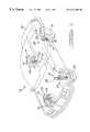
- FIG. 1is an illustration of an automobile using a plurality of semi-active fluid dampers according to the teachings of a preferred embodiment of the present invention
- FIG. 2is a schematic representation of the damper utilized in FIG. 1 using the automatic, or semi-active, damping system according to the teachings of the preferred embodiment of the present invention
- FIG. 3is a center line sectional and side elevational view of the damper shown in FIG. 2, showing the compression and rebound valves in closed positions;
- FIG. 4is a view corresponding to that shown in FIG. 3 depicting the compression and rebound valves in open positions.
- FIG. 1a plurality of four dampers 10 according to the preferred embodiment of the present invention are shown. Each damper 10 is depicted in operative association with a diagrammatic representation of a conventional automobile 12 .
- Automobile 12provides a rear suspension system 14 having a transversely extending rear axle assembly (not shown) adapted to operatively support the vehicle's rear wheels 16 .
- the rear axle assemblyis operatively connected to the automobile 12 by means of a pair of dampers 10 as well as by helical coil springs 18 .
- automobile 12has a front suspension system 20 including a transversely extending front axle assembly (not shown) which operatively supports the front wheels 22 .
- the front axle assemblyis operatively connected to the automobile 12 by means of a second pair of dampers 10 and by the helical coil springs 24 .
- the dampers 10serve to damp the relative movement of the unsprung portion (i.e., the front and rear suspension systems 20 and 14 ) and the sprung portion (i.e., the body 26 ) of the automobile 12 .
- the automobile 12has been depicted as a passenger car, the damper 10 may be used with other types of automotive vehicles or in other types of vehicles or system applications.
- the term “damper” as used hereinwill refer to dampers in general and will include shock absorbers and McPherson struts.
- an electronic control module 28is electrically connected to the dampers. As depicted in FIG. 1, each damper 10 is provided with a dedicated electronic control module 28 . Each control module 28 is used for controlling operation of each damper 10 in order to provide appropriate damping characteristics during compression and rebound resulting from movement of the body 26 of the automobile 12 . While the present invention is being illustrated with dedicated control modules 28 , it is within the scope of the present invention to utilize a single control module communicating with each damper 10 . Various techniques are known in the art for implementing electronic control modules in conjunction with dampers in order to regulate damping characteristics of a damper through variation of fluid flow valves in the damper.
- the electronic control module 28can be used to generate an electronic control signal for separately and concurrently setting desirable compression and rebound damping characteristic of the damper 10 to which it is connected.
- the damper 10to retain the damper 10 to an automotive vehicle 12 , the damper 10 includes an upper end fitting 30 and a lower end fitting 32 .
- the upper end fitting 30extends through an upper cap portion 34 and is connected to a vehicle body structure, such as a shock tower (not shown).
- the lower end fitting 32is connected to the damper 10 adjacent a lower cap portion 36 so as to secure the damper 10 to one of the suspension systems 14 and 20 .
- other suitable meansmay be used to secure the damper, or dampers, 10 to the automotive vehicle 12 .
- the damper 10 of this inventioncomprises an elongated tubular pressure cylinder 38 defining a damping fluid-containing working chamber 40 , and disposed within the chamber 40 is a reciprocal piston 42 .
- the reciprocal piston 42is secured to one end of an axially extending piston post 44 which is in turn secured to one end of an axially extending piston rod 46 .
- the piston 42can be secured directly to one end of piston rod 46 .
- the piston 42carries an annular TEFLONTM sleeve 48 which is trapped on the outer circumference of the piston to permit movement of the piston with respect to the pressure cylinder 38 without generating undue frictional forces.
- piston 42is further provided with a bi-directional flow valve 43 which allows regulated flow of damping fluid from one side of the piston to the other, or alternatively, is provided with at least a pair of uni-directional flow valves arranged on piston 42 for opposite-directional fluid flow therethrough.
- piston valvesare presently known in the art which include spring biased valves with valve seats which provide fluid flow in a regulated manner above a threshold pressure, or alternatively, metering pins and orifices which variably regulate fluid flow depending on exerted pressure therethrough.
- a further explanation of the construction and operation of pistons and piston valvesis disclosed in U.S. Pat. No. 4,113,072, which is hereby incorporated by reference.
- a base valve 50is located within the lower end of the pressure cylinder 38 and is used to control the flow of damping fluid between the working chamber 40 and an annular fluid reservoir 52 .
- the annular fluid reservoir 52is defined as the space between the outer periphery of a compression transfer tube 54 , a circumferential interface ring 56 , and a rebound transfer tube 58 and the inner periphery of a reservoir tube 60 forming the exterior surface of the damper 10 .
- the operation of base valve 50is similar to the operation of the base valve shown in U.S. Pat. No. 3,757,910, which is hereby incorporated by reference. However, other types of base valves may be used.
- reservoir tube 60 of damper 10may support a spring base flange 62 such that flange 62 is received circumferentially about tube 60 where it is welded. Additionally, a support collar 64 is received circumferentially about the piston rod 46 where it exits through upper cap portion 34 such that the collar 64 is retained atop the upper cap portion 34 .
- the spring base flange 62receives a bottom end of a helical coil spring 18 (as depicted in FIG. 1) which is circumferentially carried about the top end of the damper 10 .
- a spring cap(not shown) is received on the top of spring 18 such that a hole in the cap mates with a collar 68 formed on piston rod 46 and abuts with a corresponding shoulder 70 onto which it is trapped by threading a nut (not shown) onto threaded end 66 .
- the spring capis first loaded onto the threaded end 66 before loading end 66 into a receiving hole formed in vehicle body shock tower (not shown), such that a nut is threaded onto end 66 which traps the shock tower and spring cap to the end of the piston rod 46 .
- each aperture 72 and 74are provided through reservoir tube 60 , on opposite sides, such that each receives a compression valve 76 and a rebound valve 78 , respectively.
- the compression valve 76 and rebound valve 78fluidly communicate with a circumferential interface ring 56 against which they are sealingly retained.
- each aperture 72 and 74is circumferentially welded to a valve housing of each valve 76 and 78 .
- Reciprocating motion of the piston 42 and the piston rod 46 within the pressure cylinder 38is axially guided by sliding contact of annular TEFLON sleeve 48 within the pressure cylinder 28 at one end, and by sliding and sealing reciprocation of the piston rod 46 through a rod guide 80 which is supported by the upper cap portion 34 to seal the top end of the damper 10 , and slidably seal the piston rod as it exits therethrough.
- rod guideswhich incorporate single and multiple circumferential seals are well known in the art for sealing and seating the ends of dampers.
- Reciprocation of the piston 42 within the work chamber 40 formed inside pressure cylinder 38partitions the work chamber to define a variable volume compression chamber 82 and a variable volume rebound chamber 84 .
- Damping fluidis provided in both the compression chamber 82 and the rebound chamber 84 .
- a rebound transfer volume 86is formed between the exterior surface of the pressure cylinder 38 and the interior surface of the rebound transfer tube 58 , and is further defined at either end by the rod guide 80 and the circumferential interface ring 56 , respectively, with which they seal.
- a rebound connection opening 88is formed in the pressure cylinder 38 proximate the rod guide 80 which provides damping fluid flow between the rebound transfer volume 86 and the rebound chamber 84 . If desired, opening 88 can be formed in rod guide 80 . Additionally, the rebound transfer volume 86 communicates through rebound transfer tube 58 with rebound valve 78 .
- a compression transfer volume 90is formed between the exterior surface of the pressure cylinder 38 and the interior surface of the compression transfer tube 54 , and is further defined at either end by base valve 50 and circumferential inner face ring 56 , respectively, with which they seal.
- a compression connection opening 92is formed in the pressure cylinder 38 proximate the base valve 50 which provides damping fluid flow between the compression transfer volume 90 and the compression chamber 82 . Additionally, the compression transfer volume 90 communicates through the compression transfer tube 54 with the compression valve 76 .
- the base valve 50mates within the pressure cylinder 38 at one end as a decreased diameter shoulder 94 on the valve 50 is received within pressure cylinder 38 where it substantially circumferentially seals therebetween, and an annular face 96 on the valve 50 seats against both ends of pressure cylinder 38 and compression transfer tube 54 such that a seal is formed therebetween which cooperates in defining the compression transfer volume 90 .
- the base valve 50is circumferentially welded to the end of the compression transfer tube 54 .
- the base valve 50is provided with a fluid aperture 98 which controllably regulates a bidirectional fluid flow between the compression chamber 82 and the fluid reservoir 52 .
- Various other forms of base valvesare presently known in the art for providing bidirectional flow in the bottom of a damper.
- the compression valve 76 and rebound valve 78sealingly fasten to the reservoir tube 60 such that they extend through apertures 72 and 74 , respectively, and abut and seal in fluid communication with fluid ports provided in circumferential interface ring 56 .
- the compression valve 76has a solenoid 102 in electrical communication through a flex cable 104 with the accompanying electronic control module 28 which selectively electrically sends signals to engage and disengage the solenoid which opens and closes the compression valve 76 .
- the solenoid 102By electrically activating the solenoid 102 , the compression valve 76 is opened which provides a flow of damping fluid from the compression transfer volume 90 into the annular fluid reservoir 52 in response to compressive motion of piston 42 toward the compression chamber 82 .
- the rebound valve 78has a solenoid 106 in electrical communication through a flex cable 108 with the same electronic control module 28 which selectively electrically activates and deactivates the solenoid to close and open, respectively, the rebound valve 78 .
- solenoid 106in electrical communication through a flex cable 108 with the same electronic control module 28 which selectively electrically activates and deactivates the solenoid to close and open, respectively, the rebound valve 78 .
- Primary fluid flow between the compression chamber 82 and the rebound chamber 84is provided by damping fluid which flows through the piston aperture 43 .
- fluid flow between the compression chamber 82 and rebound chamber 84can be tailored to provide adjustable stiffness of the damper 10 in an independent manner for both pressure cycles and rebound cycles.
- damping fluidtravels a circuitous path. Damping fluid compressed in the compression chamber 82 is passed through the base valve 50 which empties into the fluid reservoir 52 . Concurrently, damping fluid in compression chamber 82 exits through the compression connection opening 92 into the compression transfer volume 90 where it passes through the compression valve 76 , while in an open position, into the reservoir 52 . Further transfer of fluid from the reservoir 52 is provided through a reservoir fluid aperture 110 (FIG. 1) which is formed in the rod guide 80 for transferring fluid from the reservoir 52 into the rebound chamber 84 .
- the rebound chamber 84communicates with the rebound transfer volume through the rebound connection opening 88 such that fluid compressed in the rebound chamber is transferred through rebound transfer volume 86 through the rebound valve 78 , when in an open position, and into the annular fluid reservoir 52 which further transfers fluid through the compression connection opening 92 into the compression volume 82 .
- the solenoid 102has an axially extendable and retractable core 112 .
- the core 112is formed from a ball 114 biased by a spring 116 and a sealing plate 118 .
- the core 112moves towards a seat 120 sealing off fluid flow through the center bore of seat 120 with the ball 114 in a first stage. Fluid flow continues through the seat 120 due to a plurality of bleed holes 121 circumferentially spaced around the central bore of the seat 120 .
- the sealing plate 118seals against the seat 120 to seal off the bleed holes 121 extending through the seat 120 .
- the two stage sealing described abovereduces the water-hammer effect of closing compression valve 76 .
- a check valve 122prevents back flow from reservoir 52 to compression transfer volume 90 .
- compression valve 76is depicted with reference arrows showing flow of damper fluid through the valve while it is in an open position.
- Fluidis delivered from the compression transfer volume 90 through the compression valve 76 and into the fluid reservoir 52 via flow ports in the circumferential interface ring 56 which is mated with a valve collar 129 to the assembly of solenoid 102 to form the compression valve 76 .
- Fluid leaving the compression transfer volume 90enters a radial port 124 which opens into a circumferential upstream well 128 in the collar 129 where damping fluid is passed through a bleed disc 126 into a circumferential downstream well 130 to transfer through the center bore of seat 120 while solenoid 102 is energized.
- the upstream well 128 and the downstream well 130are integrally formed within the collar 129 .
- the bleed disc 126is seated in the ring between the upstream and downstream wells.
- the seat 120is carried in a receiving bore 136 interjacent the upstream well 128 , and fluid flows through a central aperture 138 in the bleed disc 126 where it is delivered to the center bore of seat 120 .
- fluidflows past check valve 122 into a spring port 132 which supports the check valve 122 , where damping fluid is further delivered through an exit port 134 into the reservoir 52 .
- the solenoid 106is energized such that a core 140 having an end mounted plunger ball 142 is retracted from a flow orifice 144 and a plunger seat 146 through which flow is provided, thus opening the rebound valve 78 .
- the rebound valve 78is provided in sealing abutment against flow passages provided in the circumferential interface ring 56 by welding the solenoid 106 outer housing circumferentially to aperture 74 .
- a flowpathis provided from the rebound transfer volume 86 through the interface ring 56 , into and through the rebound valve 78 , back through the interface ring 56 , and out through the compression transfer volume 90 .
- damping fluidflows from rebound transfer volume 86 into a first radial port 148 formed in the interface ring 56 which empties into a circumferential upstream well 152 , through a bleed disc 150 and into a circumferential downstream well 154 where it passes through a central aperture 158 in the bleed disc 150 for transfer through orifice 144 .
- the circumferential upstream and downstream wells 152 and 154are provided in a valve collar 157 carried in the rebound valve 78 which seats and abuts with the interface ring 56 on one side, and abuts with the solenoid 106 on the other side, and further provides a receiving bore 160 for carrying plunger seat 146 therein.
- a flow exit port 162is provided downstream of the plunger seat 146 through which damping fluid exits from flow orifice 144 and enters a second radial port 156 provided in the interface ring 156 for exit to the compression transfer volume 90 .
- the solenoid 106is activated in a retracted position which provides fluid flow through the rebound valve 78 .
- the rebound valve 78is activated, axially extending core 140 and the plunger ball 142 to seal with the plunger seat 146 and stop flow through the orifice 144 , thereby effectively shutting off the rebound valve 78 .
- the solenoid 102can be energized to open the compression valve 76 in order to provide a bypass flow of damping fluid over flow provided through the base valve 50 , as well as the flow apertures 98 provided in the piston 42 .
- the solenoid 102 and opening the compression valve 76By energizing the solenoid 102 and opening the compression valve 76 , the flow of damping fluid in the compression chamber 82 is provided into the reservoir 52 , via the various flow paths described above.
- compressive damping of the damper 10can be varied.
- the solenoid 106is de-energized to close rebound valve 78 , and is energized to open the rebound valve 78 .
- a by-pass flowis created for damping fluid in addition to fluid valves, or ports, provided in the piston 42 .
- This by-pass flowis regulated by the bleed disc 150 , valving or slots formed in the disc.
- hydraulic fluid volume passing through the rebound valveat low pressure after leaving the rebound valve, will partly fill the compression chamber 82 , via the compression transfer volume 90 .
- the damping fluidflows through the compression connection chamber 82 , via the compression transfer volume 90 .
- the damping fluidflows through the compression connection opening 92 which further meters transfer of the fluid between the compression transfer volume 90 and the compression chamber 82 .
- Each of the precedingoccurs during the rebound phase of the piston 42 in the damper 10 .
- the check valve 122 in the compression valve 76prevents damping fluid flow from being sucked into the compression chamber 82 through the compression valve 76 while the piston 42 is in rebound. Furthermore, remaining damping fluid necessary for filling the compression chamber 82 is provided through the intake of the base valve 50 as the piston 42 is moved upward toward a rebound position.
- a rebound transfer tube 58which is concentric over pressure cylinder 38 can be substituted with a transfer tube of various other design currently utilized with normal external valve damper systems currently available on the market.
- the disc valving provided through bleed discs 126 and 150can be replaced by spring valving systems which regulate fluid flow, by increased dimensions of the valve.
- various methodsmay be used for sensing accelerations or velocities of a vehicle suspension which dictate settings for tailoring damping characteristic in compression and rebound.
- accelerometerscan be provided atop each damper 10 which monitor shock conditions resulting from pitch, yaw, and roll, as well as interaction with various bumps and obstacles, such sensed signal being further processed by the electronic control module 28 and compared to determine the desired compression and rebound damping characteristics for the damper 10 .
- compression valve 76 and rebound valve 78are actuated accordingly.
- the scope of the inventionis to be measured against the scope of the following claims.
Landscapes
- Engineering & Computer Science (AREA)
- General Engineering & Computer Science (AREA)
- Mechanical Engineering (AREA)
- Vehicle Body Suspensions (AREA)
- Fluid-Damping Devices (AREA)
- Vibration Prevention Devices (AREA)
Abstract
Description
Claims (18)
Priority Applications (5)
| Application Number | Priority Date | Filing Date | Title |
|---|---|---|---|
| US09/318,301US6321888B1 (en) | 1999-05-25 | 1999-05-25 | Damper with externally mounted semi-active system |
| JP2000147353AJP3660208B2 (en) | 1999-05-25 | 2000-05-19 | damper |
| DE10025399ADE10025399C2 (en) | 1999-05-25 | 2000-05-23 | vibration |
| GB0012841AGB2350411B (en) | 1999-05-25 | 2000-05-25 | Damper with externally mounted semi-active system |
| GB0226757AGB2378231B (en) | 1999-05-25 | 2000-05-25 | Damper with externally mounted semi-active system |
Applications Claiming Priority (1)
| Application Number | Priority Date | Filing Date | Title |
|---|---|---|---|
| US09/318,301US6321888B1 (en) | 1999-05-25 | 1999-05-25 | Damper with externally mounted semi-active system |
Publications (1)
| Publication Number | Publication Date |
|---|---|
| US6321888B1true US6321888B1 (en) | 2001-11-27 |
Family
ID=23237578
Family Applications (1)
| Application Number | Title | Priority Date | Filing Date |
|---|---|---|---|
| US09/318,301Expired - LifetimeUS6321888B1 (en) | 1999-05-25 | 1999-05-25 | Damper with externally mounted semi-active system |
Country Status (4)
| Country | Link |
|---|---|
| US (1) | US6321888B1 (en) |
| JP (1) | JP3660208B2 (en) |
| DE (1) | DE10025399C2 (en) |
| GB (1) | GB2350411B (en) |
Cited By (73)
| Publication number | Priority date | Publication date | Assignee | Title |
|---|---|---|---|---|
| US20040184948A1 (en)* | 2002-09-30 | 2004-09-23 | 3M Innovative Properties Company | Colorimetric sensor |
| US20050242532A1 (en)* | 2004-01-06 | 2005-11-03 | Deo Hrishikesh V | Suspension system with independent control of ride-height, stiffness and damping |
| US20060225979A1 (en)* | 2005-04-06 | 2006-10-12 | Quinn Shawn G | Dual stage dampers for vehicles suspensions |
| US20070000743A1 (en)* | 2005-06-29 | 2007-01-04 | Showa Corporation | Adjustable damping force hydraulic shock absorber |
| US20080087512A1 (en)* | 2006-10-11 | 2008-04-17 | Tenneco Automotive Operating Company, Inc. | Shock absorber having a continuously variable semi-active valve |
| US20080251331A1 (en)* | 2007-04-16 | 2008-10-16 | Tenneco Automotive Operating Company, Inc. | Shock absorber having a continuously variable valve with base line valving |
| US20090032346A1 (en)* | 2007-07-31 | 2009-02-05 | Tenneco Automotive Operating Company, Inc. | Semi third tube design |
| US20090035179A1 (en)* | 2002-09-30 | 2009-02-05 | 3M Innovative Properties Company | Colorimetric sensor |
| US7699147B2 (en)* | 2000-12-16 | 2010-04-20 | Thyssenkrupp Bilstein Suspension Gmbh | Regulated dashpot with shock-absorption force controls |
| US20120181766A1 (en)* | 2011-01-17 | 2012-07-19 | Tenneco Automotive Operating Company Inc. | Damper tube reinforcement sleeve |
| US8534687B2 (en) | 2010-07-05 | 2013-09-17 | Fluid Ride Ltd. | Suspension strut for a vehicle |
| US9062737B2 (en) | 2012-06-04 | 2015-06-23 | Mclaren Automotive Limited | Shock absorber with four chambers |
| US9080631B2 (en) | 2013-02-26 | 2015-07-14 | Mclaren Automotive Limited | Damper unit |
| US9150077B2 (en) | 2009-10-06 | 2015-10-06 | Tenneco Automotive Operating Company Inc. | Damper with digital valve |
| US9163691B2 (en) | 2013-03-15 | 2015-10-20 | Tenneco Automotive Operating Company Inc. | Rod guide arrangement for electronically controlled valve applications |
| US9217483B2 (en) | 2013-02-28 | 2015-12-22 | Tenneco Automotive Operating Company Inc. | Valve switching controls for adjustable damper |
| CN105257762A (en)* | 2014-07-11 | 2016-01-20 | 日立汽车系统株式会社 | Shock absorber |
| US9399383B2 (en) | 2013-02-28 | 2016-07-26 | Tenneco Automotive Operating Company Inc. | Damper with integrated electronics |
| US9404551B2 (en) | 2013-03-15 | 2016-08-02 | Tenneco Automotive Operating Company Inc. | Rod guide assembly with multi-piece valve assembly |
| US9574582B2 (en) | 2012-04-23 | 2017-02-21 | Fluid Ride, Ltd. | Hydraulic pump system and method of operation |
| US9879748B2 (en) | 2013-03-15 | 2018-01-30 | Tenneco Automotive Operating Company Inc. | Two position valve with face seal and pressure relief port |
| US9879746B2 (en) | 2013-03-15 | 2018-01-30 | Tenneco Automotive Operating Company Inc. | Rod guide system and method with multiple solenoid valve cartridges and multiple pressure regulated valve assemblies |
| US9884533B2 (en) | 2013-02-28 | 2018-02-06 | Tenneco Automotive Operating Company Inc. | Autonomous control damper |
| US9944147B1 (en)* | 2015-01-14 | 2018-04-17 | S. Gregory Smith | Combination shock and small deflection mitigator with tire wall control in cornering |
| US20180128339A1 (en)* | 2015-05-20 | 2018-05-10 | Zf Friedrichshafen Ag | Vibration Damper With An External Housing |
| US10054182B2 (en) | 2016-12-15 | 2018-08-21 | Tenneco Automotive Operating Company Inc. | Baffle tube for damper with electromechanical valve |
| US20180355940A1 (en)* | 2017-06-07 | 2018-12-13 | Zf Friedrichshafen Ag | Adjustable Oscillation Damper |
| US20190001783A1 (en)* | 2017-06-28 | 2019-01-03 | Tenneco Automotive Operating Company Inc. | Damper With Volume Reducing Insert |
| US20190186582A1 (en)* | 2016-08-08 | 2019-06-20 | Thyssenkrupp Bilstein Gmbh | Vibration damper and connection element for connecting a shock absorber tube to an add-on unit for vehicles |
| US10406883B2 (en) | 2009-10-13 | 2019-09-10 | Fox Factory, Inc. | Methods and apparatus for controlling a fluid damper |
| US10415662B2 (en) | 2009-01-07 | 2019-09-17 | Fox Factory, Inc. | Remotely operated bypass for a suspension damper |
| US10443671B2 (en) | 2009-01-07 | 2019-10-15 | Fox Factory, Inc. | Remotely operated bypass for a suspension damper |
| US10479160B2 (en) | 2017-06-06 | 2019-11-19 | Tenneco Automotive Operating Company Inc. | Damper with printed circuit board carrier |
| US10550909B2 (en) | 2008-08-25 | 2020-02-04 | Fox Factory, Inc. | Methods and apparatus for suspension lock out and signal generation |
| US10588233B2 (en) | 2017-06-06 | 2020-03-10 | Tenneco Automotive Operating Company Inc. | Damper with printed circuit board carrier |
| US10670106B2 (en) | 2009-01-07 | 2020-06-02 | Fox Factory, Inc. | Method and apparatus for an adjustable damper |
| DE102018220630A1 (en)* | 2018-11-29 | 2020-06-04 | Thyssenkrupp Ag | Adjustable vibration damper and vehicle with such a vibration damper |
| US10697514B2 (en) | 2010-01-20 | 2020-06-30 | Fox Factory, Inc. | Remotely operated bypass for a suspension damper |
| US10704641B2 (en) | 2017-12-15 | 2020-07-07 | Tenneco Automotive Operating Company Inc. | Baffle for damper with electromechanical valve |
| US10723409B2 (en) | 2009-01-07 | 2020-07-28 | Fox Factory, Inc. | Method and apparatus for an adjustable damper |
| US10737546B2 (en)* | 2016-04-08 | 2020-08-11 | Fox Factory, Inc. | Electronic compression and rebound control |
| US10759247B2 (en) | 2011-09-12 | 2020-09-01 | Fox Factory, Inc. | Methods and apparatus for suspension set up |
| US10781879B2 (en) | 2009-01-07 | 2020-09-22 | Fox Factory, Inc. | Bypass for a suspension damper |
| US10800220B2 (en) | 2009-01-07 | 2020-10-13 | Fox Factory, Inc. | Method and apparatus for an adjustable damper |
| US10821795B2 (en) | 2009-01-07 | 2020-11-03 | Fox Factory, Inc. | Method and apparatus for an adjustable damper |
| US10837515B2 (en) | 2019-02-11 | 2020-11-17 | Tenneco Automotive Operating Company Inc. | Damper baffle tube with elastomeric skirt |
| US10859133B2 (en) | 2012-05-10 | 2020-12-08 | Fox Factory, Inc. | Method and apparatus for an adjustable damper |
| US11007834B2 (en) | 2016-12-15 | 2021-05-18 | Tenneco Automotive Operating Company Inc. | Baffle tube for damper with electromechanical valve |
| US11021204B2 (en) | 2008-11-25 | 2021-06-01 | Fox Factory, Inc. | Seat post |
| US20210178850A1 (en)* | 2019-12-12 | 2021-06-17 | Ford Global Technologies, Llc | Suspension system for a vehicle |
| US11118649B2 (en) | 2019-07-01 | 2021-09-14 | Tenneco Automotive Operating Company Inc. | Damper with side collector and external control valves |
| US11143260B2 (en) | 2018-12-28 | 2021-10-12 | Tenneco Automotive Operating Company Inc. | Damper with single external control valve |
| US11156261B2 (en) | 2018-12-28 | 2021-10-26 | Tenneco Automotive Operating Company Inc. | Damper with multiple external control valves |
| US11168758B2 (en) | 2009-01-07 | 2021-11-09 | Fox Factory, Inc. | Method and apparatus for an adjustable damper |
| US11248677B2 (en) | 2019-07-18 | 2022-02-15 | Tenneco Automotive Operating Company Inc. | Pre-assembled piston accumulator insert device |
| US20220049755A1 (en)* | 2020-08-14 | 2022-02-17 | DRiV Automotive Inc. | Damper assembly including intake valve in fluid chamber |
| US11279199B2 (en) | 2012-01-25 | 2022-03-22 | Fox Factory, Inc. | Suspension damper with by-pass valves |
| US11299233B2 (en) | 2009-01-07 | 2022-04-12 | Fox Factory, Inc. | Method and apparatus for an adjustable damper |
| US11306798B2 (en) | 2008-05-09 | 2022-04-19 | Fox Factory, Inc. | Position sensitive suspension damping with an active valve |
| US11313430B2 (en)* | 2019-03-28 | 2022-04-26 | Thyssenkrupp Bilstein Gmbh | Vibration damper, motor vehicle and method for mounting a vibration damper |
| US11434971B2 (en) | 2020-08-31 | 2022-09-06 | DRiV Automotive Inc. | Damper assembly including valve connectors having one-way valves |
| US11519477B2 (en) | 2009-01-07 | 2022-12-06 | Fox Factory, Inc. | Compression isolator for a suspension damper |
| US11555525B2 (en)* | 2019-08-28 | 2023-01-17 | Thyssenkrupp Bilstenn Gmbh | Vibration damper having an adjustable damping force |
| US11619278B2 (en) | 2009-03-19 | 2023-04-04 | Fox Factory, Inc. | Methods and apparatus for suspension adjustment |
| US11635122B2 (en) | 2019-07-18 | 2023-04-25 | Tenneco Automotive Operating Company Inc. | Intake device for a damper having a side collector |
| US11655873B2 (en) | 2009-03-19 | 2023-05-23 | Fox Factory, Inc. | Methods and apparatus for suspension adjustment |
| US20230213080A1 (en)* | 2022-01-03 | 2023-07-06 | DRiV Automotive Inc. | Damper with a slanted elliptical seal between an intermediate tube and an inner pressure tube |
| US11719305B2 (en) | 2019-11-08 | 2023-08-08 | DRiV Automotive Inc. | Balanced continuously semi-active damper |
| US11796028B2 (en) | 2011-05-31 | 2023-10-24 | Fox Factory, Inc. | Methods and apparatus for position sensitive suspension damping |
| US11859690B2 (en) | 2009-10-13 | 2024-01-02 | Fox Factory, Inc. | Suspension system |
| US11866110B2 (en) | 2010-07-02 | 2024-01-09 | Fox Factory, Inc. | Lever assembly for positive lock adjustable seat post |
| US12103349B2 (en) | 2009-03-19 | 2024-10-01 | Fox Factory, Inc. | Methods and apparatus for selective spring pre-load adjustment |
| US12122205B2 (en) | 2009-01-07 | 2024-10-22 | Fox Factory, Inc. | Active valve for an internal bypass |
Families Citing this family (11)
| Publication number | Priority date | Publication date | Assignee | Title |
|---|---|---|---|---|
| DE10153011B4 (en)* | 2001-10-26 | 2006-03-09 | Zf Sachs Race Engineering Gmbh | Vibration damper with adjustable damping force |
| DE102005053394B4 (en) | 2004-11-11 | 2018-04-26 | Zf Friedrichshafen Ag | Vibration damper with adjustable damping force |
| JP2006161912A (en) | 2004-12-06 | 2006-06-22 | Yamaha Motor Co Ltd | Vehicle suspension system |
| DE102017001786B4 (en)* | 2017-02-24 | 2022-09-01 | ACE Stoßdämpfer GmbH | Sleeve for a damper, damper, system, manufacturing method for a sleeve, manufacturing method for a damper |
| DE102020214751A1 (en) | 2020-11-24 | 2022-05-25 | Volkswagen Aktiengesellschaft | Vibration dampers with external control valves |
| DE102021200915B3 (en) | 2021-02-02 | 2022-07-14 | Zf Friedrichshafen Ag | Damping valve device for a vibration damper |
| WO2023025510A1 (en)* | 2021-08-26 | 2023-03-02 | öHLINS RACING AB | Damper |
| DE102021212104A1 (en) | 2021-10-27 | 2023-04-27 | Zf Friedrichshafen Ag | Adjustable vibration damper with a hydraulic end stop |
| DE102023118619A1 (en)* | 2023-07-13 | 2025-01-16 | Dr. Ing. H.C. F. Porsche Aktiengesellschaft | Vibration damper and motor vehicle with an active chassis |
| WO2025104590A1 (en)* | 2023-11-13 | 2025-05-22 | Marelli Suspension Systems Italy S.P.A. | Tri-tube hydraulic shock absorber, particularly for vehicle suspension |
| DE102024110252A1 (en)* | 2024-04-12 | 2025-10-16 | Thyssenkrupp Ag | Vibration damper for a vehicle with a damping valve device |
Citations (19)
| Publication number | Priority date | Publication date | Assignee | Title |
|---|---|---|---|---|
| US3757910A (en) | 1971-07-29 | 1973-09-11 | Monroe Auto Equipment Co | Shock absorber and compression valve assembly |
| US3823600A (en)* | 1973-04-09 | 1974-07-16 | Us Air Force | Pneumatic linear accelerator |
| US4113072A (en) | 1976-03-22 | 1978-09-12 | Monroe Auto Equipment Company | Piston valve assembly for a shock absorber |
| US4743000A (en) | 1985-04-12 | 1988-05-10 | Robert Bosch Gmbh | Method and apparatus for controlling spring stiffness, in particular in vehicles |
| US4743046A (en) | 1985-05-13 | 1988-05-10 | Schnittger Jan R | Active vehicle suspension unit |
| US4802561A (en) | 1986-03-22 | 1989-02-07 | Boge Ag | Adjustable shock absorber |
| US4890858A (en) | 1988-02-16 | 1990-01-02 | Monroe Auto Equipment Company | Method and apparatus for controlling shock absorbers |
| US4923038A (en) | 1986-06-05 | 1990-05-08 | Lizell Magnus B | Method and apparatus for absorbing mechanical shock |
| US4986393A (en) | 1988-02-09 | 1991-01-22 | Boge Ag | Adjustable vibration dampers for motor vehicles |
| US5078240A (en) | 1989-07-21 | 1992-01-07 | Boge Ag | Adjustable vibration damper with valve body in piston having directional flow control |
| US5163706A (en)* | 1991-04-24 | 1992-11-17 | General Motors Corporation | Electro-hydraulic pressure regulating valve assembly for a hydraulic damper |
| US5201389A (en)* | 1990-07-26 | 1993-04-13 | General Motors Corporation | Method of varying a suspension damping force as a vehicle is steered |
| US5217095A (en) | 1986-06-05 | 1993-06-08 | Monroe Auto Equipment Company | Method and apparatus for absorbing mechanical shock |
| US5231583A (en) | 1990-06-08 | 1993-07-27 | Monroe Auto Equipment Company | Method and apparatus for dynamic leveling of a vehicle using an active suspension system |
| US5295563A (en)* | 1993-03-01 | 1994-03-22 | General Motors Corporation | Active suspension actuator with control flow through the piston rod |
| US5509512A (en)* | 1993-02-17 | 1996-04-23 | Fichtel & Sachs Ag | Shock absorber with adjustable damping with controlled damping characteristics |
| US5775470A (en)* | 1991-11-18 | 1998-07-07 | Itt Automotive Europe Gmbh | Hydraulic controllable vibration absorber |
| US5833036A (en)* | 1996-03-20 | 1998-11-10 | Pro-Formance Shocks, Inc. | Rebound adjustable shock absorber |
| US5944153A (en)* | 1996-10-04 | 1999-08-31 | Tokico Ltd. | Suspension control system |
Family Cites Families (5)
| Publication number | Priority date | Publication date | Assignee | Title |
|---|---|---|---|---|
| US4709791A (en)* | 1985-05-23 | 1987-12-01 | Enidine Incorporated | Adjustable double-acting damper |
| JP3146392B2 (en)* | 1992-11-20 | 2001-03-12 | トキコ株式会社 | Damping force adjustable hydraulic shock absorber |
| US5586627A (en)* | 1993-05-20 | 1996-12-24 | Tokico, Ltd. | Hydraulic shock absorber of damping force adjustable type |
| DE19542293B4 (en)* | 1994-12-03 | 2006-08-31 | Zf Sachs Race Engineering Gmbh | Vibration damper with adjustable damping force |
| US5924528A (en)* | 1997-02-21 | 1999-07-20 | Tenneco Automotive Inc. | Load depending damping assembly |
- 1999
- 1999-05-25USUS09/318,301patent/US6321888B1/ennot_activeExpired - Lifetime
- 2000
- 2000-05-19JPJP2000147353Apatent/JP3660208B2/ennot_activeExpired - Fee Related
- 2000-05-23DEDE10025399Apatent/DE10025399C2/ennot_activeExpired - Fee Related
- 2000-05-25GBGB0012841Apatent/GB2350411B/ennot_activeExpired - Fee Related
Patent Citations (21)
| Publication number | Priority date | Publication date | Assignee | Title |
|---|---|---|---|---|
| US3757910A (en) | 1971-07-29 | 1973-09-11 | Monroe Auto Equipment Co | Shock absorber and compression valve assembly |
| US3823600A (en)* | 1973-04-09 | 1974-07-16 | Us Air Force | Pneumatic linear accelerator |
| US4113072A (en) | 1976-03-22 | 1978-09-12 | Monroe Auto Equipment Company | Piston valve assembly for a shock absorber |
| US4743000A (en) | 1985-04-12 | 1988-05-10 | Robert Bosch Gmbh | Method and apparatus for controlling spring stiffness, in particular in vehicles |
| US4743046A (en) | 1985-05-13 | 1988-05-10 | Schnittger Jan R | Active vehicle suspension unit |
| US4802561A (en) | 1986-03-22 | 1989-02-07 | Boge Ag | Adjustable shock absorber |
| US5217095A (en) | 1986-06-05 | 1993-06-08 | Monroe Auto Equipment Company | Method and apparatus for absorbing mechanical shock |
| US4923038A (en) | 1986-06-05 | 1990-05-08 | Lizell Magnus B | Method and apparatus for absorbing mechanical shock |
| US5025899A (en) | 1986-06-05 | 1991-06-25 | Lizell Magnus B | Method and apparatus for absorbing mechanical shock |
| US5143186A (en) | 1986-06-05 | 1992-09-01 | Lizell Magnus B | Method and apparatus for absorbing mechanical shock |
| US4986393A (en) | 1988-02-09 | 1991-01-22 | Boge Ag | Adjustable vibration dampers for motor vehicles |
| US4890858A (en) | 1988-02-16 | 1990-01-02 | Monroe Auto Equipment Company | Method and apparatus for controlling shock absorbers |
| US5078240A (en) | 1989-07-21 | 1992-01-07 | Boge Ag | Adjustable vibration damper with valve body in piston having directional flow control |
| US5231583A (en) | 1990-06-08 | 1993-07-27 | Monroe Auto Equipment Company | Method and apparatus for dynamic leveling of a vehicle using an active suspension system |
| US5201389A (en)* | 1990-07-26 | 1993-04-13 | General Motors Corporation | Method of varying a suspension damping force as a vehicle is steered |
| US5163706A (en)* | 1991-04-24 | 1992-11-17 | General Motors Corporation | Electro-hydraulic pressure regulating valve assembly for a hydraulic damper |
| US5775470A (en)* | 1991-11-18 | 1998-07-07 | Itt Automotive Europe Gmbh | Hydraulic controllable vibration absorber |
| US5509512A (en)* | 1993-02-17 | 1996-04-23 | Fichtel & Sachs Ag | Shock absorber with adjustable damping with controlled damping characteristics |
| US5295563A (en)* | 1993-03-01 | 1994-03-22 | General Motors Corporation | Active suspension actuator with control flow through the piston rod |
| US5833036A (en)* | 1996-03-20 | 1998-11-10 | Pro-Formance Shocks, Inc. | Rebound adjustable shock absorber |
| US5944153A (en)* | 1996-10-04 | 1999-08-31 | Tokico Ltd. | Suspension control system |
Cited By (135)
| Publication number | Priority date | Publication date | Assignee | Title |
|---|---|---|---|---|
| US8651251B2 (en) | 2000-12-16 | 2014-02-18 | Thyssenkrupp Bilstein Suspension Gmbh | Regulated dashpot with shock-absorption force controls |
| US7699147B2 (en)* | 2000-12-16 | 2010-04-20 | Thyssenkrupp Bilstein Suspension Gmbh | Regulated dashpot with shock-absorption force controls |
| US20100155186A1 (en)* | 2000-12-16 | 2010-06-24 | Thyssenkrupp Bilstein Suspension Gmbh | Regulated Dashpot With Shock-Absorption Force Controls |
| US20040184948A1 (en)* | 2002-09-30 | 2004-09-23 | 3M Innovative Properties Company | Colorimetric sensor |
| US8506902B2 (en) | 2002-09-30 | 2013-08-13 | 3M Innovative Properties Company | Colorimetric sensor |
| US20090035179A1 (en)* | 2002-09-30 | 2009-02-05 | 3M Innovative Properties Company | Colorimetric sensor |
| US20050242532A1 (en)* | 2004-01-06 | 2005-11-03 | Deo Hrishikesh V | Suspension system with independent control of ride-height, stiffness and damping |
| US7963377B2 (en) | 2005-04-06 | 2011-06-21 | GM Global Technology Operations LLC | Dual stage dampers for vehicles suspensions |
| US20060225979A1 (en)* | 2005-04-06 | 2006-10-12 | Quinn Shawn G | Dual stage dampers for vehicles suspensions |
| US20070000743A1 (en)* | 2005-06-29 | 2007-01-04 | Showa Corporation | Adjustable damping force hydraulic shock absorber |
| US20080087512A1 (en)* | 2006-10-11 | 2008-04-17 | Tenneco Automotive Operating Company, Inc. | Shock absorber having a continuously variable semi-active valve |
| US7743896B2 (en)* | 2006-10-11 | 2010-06-29 | Tenneco Automotive Operating Company Inc. | Shock absorber having a continuously variable semi-active valve |
| US7926632B2 (en)* | 2007-04-16 | 2011-04-19 | Tenneco Automotive Operating Company Inc. | Shock absorber having a continuously variable valve with base line valving |
| US8511444B2 (en) | 2007-04-16 | 2013-08-20 | Tenneco Automotive Operating Company Inc. | Shock absorber having a continuously variable valve with base line valving |
| US20110139557A1 (en)* | 2007-04-16 | 2011-06-16 | Tenneco Automotive Operating Company Inc. | Shock absorber having a continuously variable valve with base line valving |
| US20080251331A1 (en)* | 2007-04-16 | 2008-10-16 | Tenneco Automotive Operating Company, Inc. | Shock absorber having a continuously variable valve with base line valving |
| US8256586B2 (en) | 2007-04-16 | 2012-09-04 | Tenneco Automotive Operating Company Inc. | Shock absorber having a continuously variable valve with base line valving |
| US20090032346A1 (en)* | 2007-07-31 | 2009-02-05 | Tenneco Automotive Operating Company, Inc. | Semi third tube design |
| US7950506B2 (en)* | 2007-07-31 | 2011-05-31 | Tenneco Automotive Operating Company Inc. | Semi third tube design |
| US11306798B2 (en) | 2008-05-09 | 2022-04-19 | Fox Factory, Inc. | Position sensitive suspension damping with an active valve |
| US10550909B2 (en) | 2008-08-25 | 2020-02-04 | Fox Factory, Inc. | Methods and apparatus for suspension lock out and signal generation |
| US11162555B2 (en) | 2008-08-25 | 2021-11-02 | Fox Factory, Inc. | Methods and apparatus for suspension lock out and signal generation |
| US11897571B2 (en) | 2008-11-25 | 2024-02-13 | Fox Factory, Inc. | Seat post |
| US11021204B2 (en) | 2008-11-25 | 2021-06-01 | Fox Factory, Inc. | Seat post |
| US11549565B2 (en) | 2009-01-07 | 2023-01-10 | Fox Factory, Inc. | Method and apparatus for an adjustable damper |
| US10821795B2 (en) | 2009-01-07 | 2020-11-03 | Fox Factory, Inc. | Method and apparatus for an adjustable damper |
| US11499601B2 (en) | 2009-01-07 | 2022-11-15 | Fox Factory, Inc. | Remotely operated bypass for a suspension damper |
| US10723409B2 (en) | 2009-01-07 | 2020-07-28 | Fox Factory, Inc. | Method and apparatus for an adjustable damper |
| US11408482B2 (en) | 2009-01-07 | 2022-08-09 | Fox Factory, Inc. | Bypass for a suspension damper |
| US12044286B2 (en) | 2009-01-07 | 2024-07-23 | Fox Factory, Inc. | Compression isolator for a suspension damper |
| US11660924B2 (en) | 2009-01-07 | 2023-05-30 | Fox Factory, Inc. | Method and apparatus for an adjustable damper |
| US11299233B2 (en) | 2009-01-07 | 2022-04-12 | Fox Factory, Inc. | Method and apparatus for an adjustable damper |
| US10670106B2 (en) | 2009-01-07 | 2020-06-02 | Fox Factory, Inc. | Method and apparatus for an adjustable damper |
| US11794543B2 (en) | 2009-01-07 | 2023-10-24 | Fox Factory, Inc. | Method and apparatus for an adjustable damper |
| US12091122B2 (en) | 2009-01-07 | 2024-09-17 | Fox Factory, Inc. | Method and apparatus for an adjustable damper |
| US11173765B2 (en) | 2009-01-07 | 2021-11-16 | Fox Factory, Inc. | Method and apparatus for an adjustable damper |
| US11168758B2 (en) | 2009-01-07 | 2021-11-09 | Fox Factory, Inc. | Method and apparatus for an adjustable damper |
| US11866120B2 (en) | 2009-01-07 | 2024-01-09 | Fox Factory, Inc. | Method and apparatus for an adjustable damper |
| US11890908B2 (en) | 2009-01-07 | 2024-02-06 | Fox Factory, Inc. | Method and apparatus for an adjustable damper |
| US11976706B2 (en) | 2009-01-07 | 2024-05-07 | Fox Factory, Inc. | Remotely operated bypass for a suspension damper |
| US12377699B2 (en) | 2009-01-07 | 2025-08-05 | Fox Factory, Inc. | Method and apparatus for an adjustable damper |
| US11519477B2 (en) | 2009-01-07 | 2022-12-06 | Fox Factory, Inc. | Compression isolator for a suspension damper |
| US12371122B2 (en) | 2009-01-07 | 2025-07-29 | Fox Factory, Inc. | Method and apparatus for an adjustable damper |
| US10814689B2 (en) | 2009-01-07 | 2020-10-27 | Fox Factory, Inc. | Method and apparatus for an adjustable damper |
| US12257871B2 (en) | 2009-01-07 | 2025-03-25 | Fox Factory, Inc. | Method and apparatus for an adjustable damper |
| US12122205B2 (en) | 2009-01-07 | 2024-10-22 | Fox Factory, Inc. | Active valve for an internal bypass |
| US10807433B2 (en) | 2009-01-07 | 2020-10-20 | Fox Factory, Inc. | Method and apparatus for an adjustable damper |
| US12134293B2 (en) | 2009-01-07 | 2024-11-05 | Fox Factory, Inc. | Method and apparatus for an adjustable damper |
| US10800220B2 (en) | 2009-01-07 | 2020-10-13 | Fox Factory, Inc. | Method and apparatus for an adjustable damper |
| US10415662B2 (en) | 2009-01-07 | 2019-09-17 | Fox Factory, Inc. | Remotely operated bypass for a suspension damper |
| US10443671B2 (en) | 2009-01-07 | 2019-10-15 | Fox Factory, Inc. | Remotely operated bypass for a suspension damper |
| US10781879B2 (en) | 2009-01-07 | 2020-09-22 | Fox Factory, Inc. | Bypass for a suspension damper |
| US12163569B2 (en) | 2009-03-19 | 2024-12-10 | Fox Factory, Inc. | Methods and apparatus for suspension adjustment |
| US11920655B2 (en) | 2009-03-19 | 2024-03-05 | Fox Factory, Inc. | Methods and apparatus for suspension adjustment |
| US12103349B2 (en) | 2009-03-19 | 2024-10-01 | Fox Factory, Inc. | Methods and apparatus for selective spring pre-load adjustment |
| US11655873B2 (en) | 2009-03-19 | 2023-05-23 | Fox Factory, Inc. | Methods and apparatus for suspension adjustment |
| US11619278B2 (en) | 2009-03-19 | 2023-04-04 | Fox Factory, Inc. | Methods and apparatus for suspension adjustment |
| US9150077B2 (en) | 2009-10-06 | 2015-10-06 | Tenneco Automotive Operating Company Inc. | Damper with digital valve |
| US9810282B2 (en) | 2009-10-06 | 2017-11-07 | Tenneco Automotive Operating Company Inc. | Damper with digital valve |
| US9695900B2 (en) | 2009-10-06 | 2017-07-04 | Tenneco Automotive Operating Company Inc. | Damper with digital valve |
| US12005755B2 (en) | 2009-10-13 | 2024-06-11 | Fox Factory, Inc. | Methods and apparatus for controlling a fluid damper |
| US11279198B2 (en) | 2009-10-13 | 2022-03-22 | Fox Factory, Inc. | Methods and apparatus for controlling a fluid damper |
| US11859690B2 (en) | 2009-10-13 | 2024-01-02 | Fox Factory, Inc. | Suspension system |
| US10406883B2 (en) | 2009-10-13 | 2019-09-10 | Fox Factory, Inc. | Methods and apparatus for controlling a fluid damper |
| US10697514B2 (en) | 2010-01-20 | 2020-06-30 | Fox Factory, Inc. | Remotely operated bypass for a suspension damper |
| US11708878B2 (en) | 2010-01-20 | 2023-07-25 | Fox Factory, Inc. | Remotely operated bypass for a suspension damper |
| US11866110B2 (en) | 2010-07-02 | 2024-01-09 | Fox Factory, Inc. | Lever assembly for positive lock adjustable seat post |
| US9150076B2 (en) | 2010-07-05 | 2015-10-06 | Fluid Ride, Ltd. | Suspension strut for a vehicle |
| US8534687B2 (en) | 2010-07-05 | 2013-09-17 | Fluid Ride Ltd. | Suspension strut for a vehicle |
| US10125841B2 (en) | 2010-07-05 | 2018-11-13 | Fluid Ride, Ltd. | Suspension strut for a vehicle |
| US20120181766A1 (en)* | 2011-01-17 | 2012-07-19 | Tenneco Automotive Operating Company Inc. | Damper tube reinforcement sleeve |
| US8408569B2 (en)* | 2011-01-17 | 2013-04-02 | Tenneco Automotive Operating Company Inc. | Damper tube reinforcement sleeve |
| US11796028B2 (en) | 2011-05-31 | 2023-10-24 | Fox Factory, Inc. | Methods and apparatus for position sensitive suspension damping |
| US11958328B2 (en) | 2011-09-12 | 2024-04-16 | Fox Factory, Inc. | Methods and apparatus for suspension set up |
| US10759247B2 (en) | 2011-09-12 | 2020-09-01 | Fox Factory, Inc. | Methods and apparatus for suspension set up |
| US11279199B2 (en) | 2012-01-25 | 2022-03-22 | Fox Factory, Inc. | Suspension damper with by-pass valves |
| US11760150B2 (en) | 2012-01-25 | 2023-09-19 | Fox Factory, Inc. | Suspension damper with by-pass valves |
| US9574582B2 (en) | 2012-04-23 | 2017-02-21 | Fluid Ride, Ltd. | Hydraulic pump system and method of operation |
| US12038062B2 (en) | 2012-05-10 | 2024-07-16 | Fox Factory, Inc. | Method and apparatus for an adjustable damper |
| US11629774B2 (en) | 2012-05-10 | 2023-04-18 | Fox Factory, Inc. | Method and apparatus for an adjustable damper |
| US10859133B2 (en) | 2012-05-10 | 2020-12-08 | Fox Factory, Inc. | Method and apparatus for an adjustable damper |
| US9062737B2 (en) | 2012-06-04 | 2015-06-23 | Mclaren Automotive Limited | Shock absorber with four chambers |
| US9080631B2 (en) | 2013-02-26 | 2015-07-14 | Mclaren Automotive Limited | Damper unit |
| US9802456B2 (en) | 2013-02-28 | 2017-10-31 | Tenneco Automotive Operating Company Inc. | Damper with integrated electronics |
| US9925842B2 (en) | 2013-02-28 | 2018-03-27 | Tenneco Automotive Operating Company Inc. | Valve switching controls for adjustable damper |
| US9217483B2 (en) | 2013-02-28 | 2015-12-22 | Tenneco Automotive Operating Company Inc. | Valve switching controls for adjustable damper |
| US9884533B2 (en) | 2013-02-28 | 2018-02-06 | Tenneco Automotive Operating Company Inc. | Autonomous control damper |
| US10000104B2 (en) | 2013-02-28 | 2018-06-19 | Tenneco Automotive Operating Company Inc. | Damper with integrated electronics |
| US9399383B2 (en) | 2013-02-28 | 2016-07-26 | Tenneco Automotive Operating Company Inc. | Damper with integrated electronics |
| US9404551B2 (en) | 2013-03-15 | 2016-08-02 | Tenneco Automotive Operating Company Inc. | Rod guide assembly with multi-piece valve assembly |
| US9879748B2 (en) | 2013-03-15 | 2018-01-30 | Tenneco Automotive Operating Company Inc. | Two position valve with face seal and pressure relief port |
| US9879746B2 (en) | 2013-03-15 | 2018-01-30 | Tenneco Automotive Operating Company Inc. | Rod guide system and method with multiple solenoid valve cartridges and multiple pressure regulated valve assemblies |
| US9163691B2 (en) | 2013-03-15 | 2015-10-20 | Tenneco Automotive Operating Company Inc. | Rod guide arrangement for electronically controlled valve applications |
| CN105257762B (en)* | 2014-07-11 | 2019-10-15 | 日立汽车系统株式会社 | buffer |
| US10215250B2 (en)* | 2014-07-11 | 2019-02-26 | Hitachi Automotive Systems, Ltd. | Shock absorber |
| CN105257762A (en)* | 2014-07-11 | 2016-01-20 | 日立汽车系统株式会社 | Shock absorber |
| US9944147B1 (en)* | 2015-01-14 | 2018-04-17 | S. Gregory Smith | Combination shock and small deflection mitigator with tire wall control in cornering |
| US10514077B2 (en)* | 2015-05-20 | 2019-12-24 | Zf Friedrichshafen Ag | Vibration damper with an external housing |
| US20180128339A1 (en)* | 2015-05-20 | 2018-05-10 | Zf Friedrichshafen Ag | Vibration Damper With An External Housing |
| US11472252B2 (en)* | 2016-04-08 | 2022-10-18 | Fox Factory, Inc. | Electronic compression and rebound control |
| US10737546B2 (en)* | 2016-04-08 | 2020-08-11 | Fox Factory, Inc. | Electronic compression and rebound control |
| US20190186582A1 (en)* | 2016-08-08 | 2019-06-20 | Thyssenkrupp Bilstein Gmbh | Vibration damper and connection element for connecting a shock absorber tube to an add-on unit for vehicles |
| US11236796B2 (en)* | 2016-08-08 | 2022-02-01 | Thyssenkrupp Bilstein Gmbh | Vibration damper and connection element for connecting a shock absorber tube to an add-on unit for vehicles |
| US10054182B2 (en) | 2016-12-15 | 2018-08-21 | Tenneco Automotive Operating Company Inc. | Baffle tube for damper with electromechanical valve |
| US11007834B2 (en) | 2016-12-15 | 2021-05-18 | Tenneco Automotive Operating Company Inc. | Baffle tube for damper with electromechanical valve |
| US10479160B2 (en) | 2017-06-06 | 2019-11-19 | Tenneco Automotive Operating Company Inc. | Damper with printed circuit board carrier |
| US10588233B2 (en) | 2017-06-06 | 2020-03-10 | Tenneco Automotive Operating Company Inc. | Damper with printed circuit board carrier |
| US10655701B2 (en)* | 2017-06-07 | 2020-05-19 | Zf Friedrichshafen Ag | Adjustable oscillation damper |
| US20180355940A1 (en)* | 2017-06-07 | 2018-12-13 | Zf Friedrichshafen Ag | Adjustable Oscillation Damper |
| US20190001783A1 (en)* | 2017-06-28 | 2019-01-03 | Tenneco Automotive Operating Company Inc. | Damper With Volume Reducing Insert |
| US10987988B2 (en)* | 2017-06-28 | 2021-04-27 | Tenneco Automotive Operating Company Inc. | Damper with volume reducing insert |
| US10704641B2 (en) | 2017-12-15 | 2020-07-07 | Tenneco Automotive Operating Company Inc. | Baffle for damper with electromechanical valve |
| DE102018220630A1 (en)* | 2018-11-29 | 2020-06-04 | Thyssenkrupp Ag | Adjustable vibration damper and vehicle with such a vibration damper |
| DE102018220630B4 (en) | 2018-11-29 | 2024-01-11 | Thyssenkrupp Ag | Adjustable vibration damper and vehicle with such a vibration damper |
| US11391337B2 (en)* | 2018-11-29 | 2022-07-19 | Thyssenkrupp Bilstein Gmbh | Adjustable vibration damper and vehicle having such a vibration damper |
| CN111237377A (en)* | 2018-11-29 | 2020-06-05 | 蒂森克虏伯比尔斯坦有限公司 | Adjustable vibration damper and vehicle with same |
| US11143260B2 (en) | 2018-12-28 | 2021-10-12 | Tenneco Automotive Operating Company Inc. | Damper with single external control valve |
| US11156261B2 (en) | 2018-12-28 | 2021-10-26 | Tenneco Automotive Operating Company Inc. | Damper with multiple external control valves |
| US10837515B2 (en) | 2019-02-11 | 2020-11-17 | Tenneco Automotive Operating Company Inc. | Damper baffle tube with elastomeric skirt |
| US11313430B2 (en)* | 2019-03-28 | 2022-04-26 | Thyssenkrupp Bilstein Gmbh | Vibration damper, motor vehicle and method for mounting a vibration damper |
| US11118649B2 (en) | 2019-07-01 | 2021-09-14 | Tenneco Automotive Operating Company Inc. | Damper with side collector and external control valves |
| US11248677B2 (en) | 2019-07-18 | 2022-02-15 | Tenneco Automotive Operating Company Inc. | Pre-assembled piston accumulator insert device |
| US11635122B2 (en) | 2019-07-18 | 2023-04-25 | Tenneco Automotive Operating Company Inc. | Intake device for a damper having a side collector |
| US11555525B2 (en)* | 2019-08-28 | 2023-01-17 | Thyssenkrupp Bilstenn Gmbh | Vibration damper having an adjustable damping force |
| US11719305B2 (en) | 2019-11-08 | 2023-08-08 | DRiV Automotive Inc. | Balanced continuously semi-active damper |
| US11511592B2 (en)* | 2019-12-12 | 2022-11-29 | Ford Global Technologies, Llc | Suspension system for a vehicle |
| US20210178850A1 (en)* | 2019-12-12 | 2021-06-17 | Ford Global Technologies, Llc | Suspension system for a vehicle |
| US20220049755A1 (en)* | 2020-08-14 | 2022-02-17 | DRiV Automotive Inc. | Damper assembly including intake valve in fluid chamber |
| US11441633B2 (en)* | 2020-08-14 | 2022-09-13 | DRiV Automotive Inc. | Damper assembly including intake valve in fluid chamber |
| CN114076166A (en)* | 2020-08-14 | 2022-02-22 | DRiV汽车公司 | Damper assembly including suction valve in fluid chamber |
| US11434971B2 (en) | 2020-08-31 | 2022-09-06 | DRiV Automotive Inc. | Damper assembly including valve connectors having one-way valves |
| WO2023129312A1 (en)* | 2022-01-03 | 2023-07-06 | DRiV Automotive Inc. | Damper with a slanted elliptical seal between an intermediate tube and an inner pressure tube |
| US20230213080A1 (en)* | 2022-01-03 | 2023-07-06 | DRiV Automotive Inc. | Damper with a slanted elliptical seal between an intermediate tube and an inner pressure tube |
| US11906015B2 (en)* | 2022-01-03 | 2024-02-20 | DRiV Automotive Inc. | Damper with a slanted elliptical seal between an intermediate tube and an inner pressure tube |
| US12146548B2 (en) | 2022-01-03 | 2024-11-19 | DRiV Automotive Inc. | Damper with a slanted elliptical seal |
Also Published As
| Publication number | Publication date |
|---|---|
| GB2350411B (en) | 2003-01-15 |
| JP3660208B2 (en) | 2005-06-15 |
| JP2001027275A (en) | 2001-01-30 |
| DE10025399A1 (en) | 2000-12-21 |
| GB2350411A (en) | 2000-11-29 |
| GB0012841D0 (en) | 2000-07-19 |
| DE10025399C2 (en) | 2003-11-13 |
Similar Documents
| Publication | Publication Date | Title |
|---|---|---|
| US6321888B1 (en) | Damper with externally mounted semi-active system | |
| KR101454050B1 (en) | Shock absorber having a continuously variable valve with base line valving | |
| US7950506B2 (en) | Semi third tube design | |
| US5598903A (en) | Acceleration sensitive flow sensitive mcpherson strut | |
| US5934422A (en) | Step motor actuated continuously variable shock absorber | |
| US5460355A (en) | Adjustable shock absorber | |
| JP2930416B2 (en) | Method and apparatus for controlling a shock absorber | |
| CN101541571B (en) | Shock absorber with stepless semi-active valve | |
| EP3067584B1 (en) | Vehicle suspension system | |
| US8511447B2 (en) | Triple tube shock absorber having a shortened intermediate tube | |
| US20130081913A1 (en) | Welding of transfer ring on round tube | |
| US6332622B1 (en) | Suspension apparatus having two interconnected shock absorbers | |
| US5152379A (en) | Adjustable shock absorber assembly | |
| US7252181B2 (en) | Air pressure proportional damper | |
| EP1312828B1 (en) | Acceleration sensitive damper | |
| US5113979A (en) | Base valve for a shock absorber | |
| EP0572040A1 (en) | Method and apparatus for absorbing mechanical shock | |
| WO1998014718A1 (en) | ACCELERATION SENSITIVE FLOW SENSITIVE McPHERSON STRUT | |
| GB2378231A (en) | A damper for a vehicle suspension with externally mounted semi-active system |
Legal Events
| Date | Code | Title | Description |
|---|---|---|---|
| AS | Assignment | Owner name:TENECO AUTOMOTIVE INC., ILLINOIS Free format text:ASSIGNMENT OF ASSIGNORS INTEREST;ASSIGNORS:REYBROUCK, KOENRAAD G.;SCHURMANS, RUDI J.;REEL/FRAME:010002/0074 Effective date:19990419 | |
| AS | Assignment | Owner name:CHASE MANHATTAN BANK, AS ADMINISTRATIVE AGENT, THE Free format text:CONDITIONAL ASSIGNMENT OF AND SECURITY INTEREST IN PATENT RIGHTS;ASSIGNOR:TENNECO AUTOMOTIVE INC. (DE CORPORATION);REEL/FRAME:011137/0170 Effective date:19991104 | |
| AS | Assignment | Owner name:TENNECO AUTOMOTIVE OPERATING COMPANY INC., ILLINOI Free format text:CHANGE OF NAME;ASSIGNOR:TENNECO AUTOMOTIVE, INC. A DELAWARE CORPORATION;REEL/FRAME:011923/0293 Effective date:19991105 | |
| STCF | Information on status: patent grant | Free format text:PATENTED CASE | |
| AS | Assignment | Owner name:JPMORGAN CHASE BANK, AS ADMINISTRATIVE AGENT, TEXA Free format text:SECURITY AGREEMENT;ASSIGNOR:TENNECO AUTOMOTIVE OPERATING COMPANY INC. (DELAWARE CORPORATION);REEL/FRAME:014475/0131 Effective date:20030728 | |
| AS | Assignment | Owner name:WACHOVIA BANK, NATIONAL ASSOCIATION, AS COLLATERAL Free format text:SECURITY AGREEMENT;ASSIGNORS:TENNECO AUTOMOTIVE INC.;TENNECO AUTOMOTIVE OPERATING COMPANY INC.;TENNECO INTERNATIONAL HOLDING CORP.;AND OTHERS;REEL/FRAME:015017/0658 Effective date:20030619 | |
| FPAY | Fee payment | Year of fee payment:4 | |
| AS | Assignment | Owner name:JPMORGAN CHASE BANK,NEW YORK Free format text:AMENDMENT TO SECURITY INTEREST IN UNITED STATES PATENTS;ASSIGNORS:TENNECO AUTOMOTIVE OPERATING COMPANY INC.;TENNECO INTERNATIONAL HOLDING CORP.;TENNECO GLOBAL HOLDINGS INC.;AND OTHERS;REEL/FRAME:019009/0247 Effective date:20070312 Owner name:JPMORGAN CHASE BANK, NEW YORK Free format text:AMENDMENT TO SECURITY INTEREST IN UNITED STATES PATENTS;ASSIGNORS:TENNECO AUTOMOTIVE OPERATING COMPANY INC.;TENNECO INTERNATIONAL HOLDING CORP.;TENNECO GLOBAL HOLDINGS INC.;AND OTHERS;REEL/FRAME:019009/0247 Effective date:20070312 | |
| FPAY | Fee payment | Year of fee payment:8 | |
| AS | Assignment | Owner name:TENNECO AUTOMOTIVE INC. (NOW KNOWN AS TENNECO INC. Free format text:RELEASE BY SECURED PARTY;ASSIGNOR:U.S. BANK NATIONAL ASSOCIATION (AS SUCCESSOR IN INTEREST TO WACHOVIA BANK, NATIONAL ASSOCIATION);REEL/FRAME:024973/0130 Effective date:20100902 Owner name:THE PULLMAN COMPANY, ILLINOIS Free format text:RELEASE BY SECURED PARTY;ASSIGNOR:U.S. BANK NATIONAL ASSOCIATION (AS SUCCESSOR IN INTEREST TO WACHOVIA BANK, NATIONAL ASSOCIATION);REEL/FRAME:024973/0130 Effective date:20100902 Owner name:TMC TEXAS INC., ILLINOIS Free format text:RELEASE BY SECURED PARTY;ASSIGNOR:U.S. BANK NATIONAL ASSOCIATION (AS SUCCESSOR IN INTEREST TO WACHOVIA BANK, NATIONAL ASSOCIATION);REEL/FRAME:024973/0130 Effective date:20100902 Owner name:TENNECO AUTOMOTIVE OPERATING COMPANY INC., ILLINOI Free format text:RELEASE BY SECURED PARTY;ASSIGNOR:U.S. BANK NATIONAL ASSOCIATION (AS SUCCESSOR IN INTEREST TO WACHOVIA BANK, NATIONAL ASSOCIATION);REEL/FRAME:024973/0130 Effective date:20100902 Owner name:TENNECO INTERNATIONAL HOLDING CORP., ILLINOIS Free format text:RELEASE BY SECURED PARTY;ASSIGNOR:U.S. BANK NATIONAL ASSOCIATION (AS SUCCESSOR IN INTEREST TO WACHOVIA BANK, NATIONAL ASSOCIATION);REEL/FRAME:024973/0130 Effective date:20100902 Owner name:TENNECO GLOBAL HOLDINGS INC., ILLINOIS Free format text:RELEASE BY SECURED PARTY;ASSIGNOR:U.S. BANK NATIONAL ASSOCIATION (AS SUCCESSOR IN INTEREST TO WACHOVIA BANK, NATIONAL ASSOCIATION);REEL/FRAME:024973/0130 Effective date:20100902 Owner name:CLEVITE INDUSTRIES INC., ILLINOIS Free format text:RELEASE BY SECURED PARTY;ASSIGNOR:U.S. BANK NATIONAL ASSOCIATION (AS SUCCESSOR IN INTEREST TO WACHOVIA BANK, NATIONAL ASSOCIATION);REEL/FRAME:024973/0130 Effective date:20100902 | |
| FPAY | Fee payment | Year of fee payment:12 | |
| AS | Assignment | Owner name:JPMORGAN CHASE BANK, N.A., AS ADMINISTRATIVE AGENT, ILLINOIS Free format text:GRANT OF SECURITY INTEREST IN PATENT RIGHTS;ASSIGNOR:TENNECO AUTOMOTIVE OPERATING COMPANY INC.;REEL/FRAME:042809/0515 Effective date:20170512 Owner name:JPMORGAN CHASE BANK, N.A., AS ADMINISTRATIVE AGENT Free format text:GRANT OF SECURITY INTEREST IN PATENT RIGHTS;ASSIGNOR:TENNECO AUTOMOTIVE OPERATING COMPANY INC.;REEL/FRAME:042809/0515 Effective date:20170512 | |
| AS | Assignment | Owner name:WILMINGTON TRUST, NATIONAL ASSOCIATION, AS COLLATERAL TRUSTEE, MINNESOTA Free format text:CONFIRMATORY GRANT OF SECURITY INTERESTS IN UNITED STATES PATENTS;ASSIGNORS:TENNECO INC.;TENNECO AUTOMOTIVE OPERATING COMPANY INC.;TENNECO INTERNATIONAL HOLDING CORP.;AND OTHERS;REEL/FRAME:047223/0001 Effective date:20181001 Owner name:WILMINGTON TRUST, NATIONAL ASSOCIATION, AS COLLATE Free format text:CONFIRMATORY GRANT OF SECURITY INTERESTS IN UNITED STATES PATENTS;ASSIGNORS:TENNECO INC.;TENNECO AUTOMOTIVE OPERATING COMPANY INC.;TENNECO INTERNATIONAL HOLDING CORP.;AND OTHERS;REEL/FRAME:047223/0001 Effective date:20181001 | |
| AS | Assignment | Owner name:TENNECO AUTOMOTIVE OPERATING COMPANY INC., ILLINOIS Free format text:RELEASE BY SECURED PARTY;ASSIGNOR:JPMORGAN CHASE BANK, N.A.;REEL/FRAME:048099/0716 Effective date:20181001 Owner name:TENNECO AUTOMOTIVE OPERATING COMPANY INC., ILLINOI Free format text:RELEASE BY SECURED PARTY;ASSIGNOR:JPMORGAN CHASE BANK, N.A.;REEL/FRAME:048099/0716 Effective date:20181001 | |
| AS | Assignment | Owner name:TENNECO AUTOMOTIVE OPERATING COMPANY INC., ILLINOIS Free format text:CONFIRMATION OF TERMINATION AND RELEASE OF SECURITY INTEREST IN PATENT RIGHTS (R/F 14475/0131);ASSIGNOR:JPMORGAN CHASE BANK, N.A., AS ADMINISTRATIVE AGENT;REEL/FRAME:055426/0159 Effective date:20210226 Owner name:TENNECO INTERNATIONAL HOLDING CORP., ILLINOIS Free format text:CONFIRMATION OF TERMINATION AND RELEASE OF SECURITY INTEREST IN PATENT RIGHTS (R/F 19009/0247);ASSIGNOR:JPMORGAN CHASE BANK, N.A., AS ADMINISTRATIVE AGENT;REEL/FRAME:055429/0284 Effective date:20210226 Owner name:TMC TEXAS INC., ILLINOIS Free format text:CONFIRMATION OF TERMINATION AND RELEASE OF SECURITY INTEREST IN PATENT RIGHTS (R/F 19009/0247);ASSIGNOR:JPMORGAN CHASE BANK, N.A., AS ADMINISTRATIVE AGENT;REEL/FRAME:055429/0284 Effective date:20210226 Owner name:TENNECO AUTOMOTIVE OPERATING COMPANY INC., ILLINOIS Free format text:CONFIRMATION OF TERMINATION AND RELEASE OF SECURITY INTEREST IN PATENT RIGHTS (R/F 19009/0247);ASSIGNOR:JPMORGAN CHASE BANK, N.A., AS ADMINISTRATIVE AGENT;REEL/FRAME:055429/0284 Effective date:20210226 Owner name:THE PULLMAN COMPANY, ILLINOIS Free format text:CONFIRMATION OF TERMINATION AND RELEASE OF SECURITY INTEREST IN PATENT RIGHTS (R/F 19009/0247);ASSIGNOR:JPMORGAN CHASE BANK, N.A., AS ADMINISTRATIVE AGENT;REEL/FRAME:055429/0284 Effective date:20210226 Owner name:TENNECO INC. (FORMERLY KNOWN AS TENNECO AUTOMOTIVE INC.), ILLINOIS Free format text:CONFIRMATION OF TERMINATION AND RELEASE OF SECURITY INTEREST IN PATENT RIGHTS (R/F 19009/0247);ASSIGNOR:JPMORGAN CHASE BANK, N.A., AS ADMINISTRATIVE AGENT;REEL/FRAME:055429/0284 Effective date:20210226 Owner name:CLEVITE INDUSTRIES INC., ILLINOIS Free format text:CONFIRMATION OF TERMINATION AND RELEASE OF SECURITY INTEREST IN PATENT RIGHTS (R/F 19009/0247);ASSIGNOR:JPMORGAN CHASE BANK, N.A., AS ADMINISTRATIVE AGENT;REEL/FRAME:055429/0284 Effective date:20210226 Owner name:TENNECO GLOBAL HOLDINGS INC., ILLINOIS Free format text:CONFIRMATION OF TERMINATION AND RELEASE OF SECURITY INTEREST IN PATENT RIGHTS (R/F 19009/0247);ASSIGNOR:JPMORGAN CHASE BANK, N.A., AS ADMINISTRATIVE AGENT;REEL/FRAME:055429/0284 Effective date:20210226 | |
| AS | Assignment | Owner name:FEDERAL-MOGUL PRODUCTS US LLC, MICHIGAN Free format text:RELEASE BY SECURED PARTY;ASSIGNOR:WILMINGTON TRUST, NATIONAL ASSOCIATION;REEL/FRAME:061975/0218 Effective date:20221117 Owner name:FEDERAL-MOGUL FINANCING CORPORATION, MICHIGAN Free format text:RELEASE BY SECURED PARTY;ASSIGNOR:WILMINGTON TRUST, NATIONAL ASSOCIATION;REEL/FRAME:061975/0218 Effective date:20221117 Owner name:FEDERAL-MOGUL FILTRATION LLC, MICHIGAN Free format text:RELEASE BY SECURED PARTY;ASSIGNOR:WILMINGTON TRUST, NATIONAL ASSOCIATION;REEL/FRAME:061975/0218 Effective date:20221117 Owner name:BECK ARNLEY HOLDINGS LLC, MICHIGAN Free format text:RELEASE BY SECURED PARTY;ASSIGNOR:WILMINGTON TRUST, NATIONAL ASSOCIATION;REEL/FRAME:061975/0218 Effective date:20221117 Owner name:FEDERAL-MOGUL SEVIERVILLE, LLC, MICHIGAN Free format text:RELEASE BY SECURED PARTY;ASSIGNOR:WILMINGTON TRUST, NATIONAL ASSOCIATION;REEL/FRAME:061975/0218 Effective date:20221117 Owner name:FEDERAL-MOGUL VALVE TRAIN INTERNATIONAL LLC, MICHIGAN Free format text:RELEASE BY SECURED PARTY;ASSIGNOR:WILMINGTON TRUST, NATIONAL ASSOCIATION;REEL/FRAME:061975/0218 Effective date:20221117 Owner name:F-M TSC REAL ESTATE HOLDINGS LLC, MICHIGAN Free format text:RELEASE BY SECURED PARTY;ASSIGNOR:WILMINGTON TRUST, NATIONAL ASSOCIATION;REEL/FRAME:061975/0218 Effective date:20221117 Owner name:F-M MOTORPARTS TSC LLC, MICHIGAN Free format text:RELEASE BY SECURED PARTY;ASSIGNOR:WILMINGTON TRUST, NATIONAL ASSOCIATION;REEL/FRAME:061975/0218 Effective date:20221117 Owner name:FEDERAL-MOGUL CHASSIS LLC, MICHIGAN Free format text:RELEASE BY SECURED PARTY;ASSIGNOR:WILMINGTON TRUST, NATIONAL ASSOCIATION;REEL/FRAME:061975/0218 Effective date:20221117 Owner name:FEDERAL-MOGUL MOTORPARTS LLC, MICHIGAN Free format text:RELEASE BY SECURED PARTY;ASSIGNOR:WILMINGTON TRUST, NATIONAL ASSOCIATION;REEL/FRAME:061975/0218 Effective date:20221117 Owner name:FEDERAL-MOGUL IGNITION LLC, MICHIGAN Free format text:RELEASE BY SECURED PARTY;ASSIGNOR:WILMINGTON TRUST, NATIONAL ASSOCIATION;REEL/FRAME:061975/0218 Effective date:20221117 Owner name:FEDERAL-MOGUL PISTON RINGS, LLC, MICHIGAN Free format text:RELEASE BY SECURED PARTY;ASSIGNOR:WILMINGTON TRUST, NATIONAL ASSOCIATION;REEL/FRAME:061975/0218 Effective date:20221117 Owner name:FEDERAL-MOGUL POWERTRAIN IP LLC, MICHIGAN Free format text:RELEASE BY SECURED PARTY;ASSIGNOR:WILMINGTON TRUST, NATIONAL ASSOCIATION;REEL/FRAME:061975/0218 Effective date:20221117 Owner name:FEDERAL-MOGUL POWERTRAIN LLC, MICHIGAN Free format text:RELEASE BY SECURED PARTY;ASSIGNOR:WILMINGTON TRUST, NATIONAL ASSOCIATION;REEL/FRAME:061975/0218 Effective date:20221117 Owner name:MUZZY-LYON AUTO PARTS LLC, ILLINOIS Free format text:RELEASE BY SECURED PARTY;ASSIGNOR:WILMINGTON TRUST, NATIONAL ASSOCIATION;REEL/FRAME:061975/0218 Effective date:20221117 Owner name:FELT PRODUCTS MFG. CO. LLC, ILLINOIS Free format text:RELEASE BY SECURED PARTY;ASSIGNOR:WILMINGTON TRUST, NATIONAL ASSOCIATION;REEL/FRAME:061975/0218 Effective date:20221117 Owner name:FEDERAL-MOGUL WORLD WIDE LLC, MICHIGAN Free format text:RELEASE BY SECURED PARTY;ASSIGNOR:WILMINGTON TRUST, NATIONAL ASSOCIATION;REEL/FRAME:061975/0218 Effective date:20221117 Owner name:CARTER AUTOMOTIVE COMPANY LLC, ILLINOIS Free format text:RELEASE BY SECURED PARTY;ASSIGNOR:WILMINGTON TRUST, NATIONAL ASSOCIATION;REEL/FRAME:061975/0218 Effective date:20221117 Owner name:TMC TEXAS INC., ILLINOIS Free format text:RELEASE BY SECURED PARTY;ASSIGNOR:WILMINGTON TRUST, NATIONAL ASSOCIATION;REEL/FRAME:061975/0218 Effective date:20221117 Owner name:CLEVITE INDUSTRIES INC., OHIO Free format text:RELEASE BY SECURED PARTY;ASSIGNOR:WILMINGTON TRUST, NATIONAL ASSOCIATION;REEL/FRAME:061975/0218 Effective date:20221117 Owner name:TENNECO GLOBAL HOLDINGS INC., ILLINOIS Free format text:RELEASE BY SECURED PARTY;ASSIGNOR:WILMINGTON TRUST, NATIONAL ASSOCIATION;REEL/FRAME:061975/0218 Effective date:20221117 Owner name:THE PULLMAN COMPANY, OHIO Free format text:RELEASE BY SECURED PARTY;ASSIGNOR:WILMINGTON TRUST, NATIONAL ASSOCIATION;REEL/FRAME:061975/0218 Effective date:20221117 Owner name:TENNECO INTERNATIONAL HOLDING CORP., ILLINOIS Free format text:RELEASE BY SECURED PARTY;ASSIGNOR:WILMINGTON TRUST, NATIONAL ASSOCIATION;REEL/FRAME:061975/0218 Effective date:20221117 Owner name:TENNECO AUTOMOTIVE OPERATING COMPANY INC., ILLINOIS Free format text:RELEASE BY SECURED PARTY;ASSIGNOR:WILMINGTON TRUST, NATIONAL ASSOCIATION;REEL/FRAME:061975/0218 Effective date:20221117 Owner name:TENNECO INC., ILLINOIS Free format text:RELEASE BY SECURED PARTY;ASSIGNOR:WILMINGTON TRUST, NATIONAL ASSOCIATION;REEL/FRAME:061975/0218 Effective date:20221117 | |
| AS | Assignment | Owner name:CITIBANK, N.A., AS COLLATERAL AGENT, NEW YORK Free format text:NOTICE OF GRANT OF SECURITY INTEREST IN PATENTS (FIRST LIEN);ASSIGNORS:DRIV AUTOMOTIVE INC.;FEDERAL-MOGUL CHASSIS LLC;FEDERAL-MOGUL IGNITION LLC;AND OTHERS;REEL/FRAME:061989/0689 Effective date:20221117 | |
| AS | Assignment | Owner name:CITIBANK, N.A., AS COLLATERAL AGENT, NEW YORK Free format text:PATENT SECURITY AGREEMENT (ABL);ASSIGNORS:TENNECO INC.;DRIV AUTOMOTIVE INC.;FEDERAL-MOGUL CHASSIS LLC;AND OTHERS;REEL/FRAME:063268/0506 Effective date:20230406 |