US6321878B1 - Caster and braking system - Google Patents
Caster and braking systemDownload PDFInfo
- Publication number
- US6321878B1 US6321878B1US09/263,039US26303999AUS6321878B1US 6321878 B1US6321878 B1US 6321878B1US 26303999 AUS26303999 AUS 26303999AUS 6321878 B1US6321878 B1US 6321878B1
- Authority
- US
- United States
- Prior art keywords
- brake
- caster
- shaft
- base frame
- movement
- Prior art date
- Legal status (The legal status is an assumption and is not a legal conclusion. Google has not performed a legal analysis and makes no representation as to the accuracy of the status listed.)
- Expired - Lifetime
Links
- 230000002401inhibitory effectEffects0.000claimsabstractdescription5
- 238000006073displacement reactionMethods0.000claimsdescription16
- 230000007935neutral effectEffects0.000claimsdescription14
- 230000008878couplingEffects0.000claimsdescription9
- 238000010168coupling processMethods0.000claimsdescription9
- 238000005859coupling reactionMethods0.000claimsdescription9
- 230000004044responseEffects0.000claimsdescription5
- 230000007246mechanismEffects0.000description62
- 125000006850spacer groupChemical group0.000description5
- 238000003466weldingMethods0.000description4
- 230000000903blocking effectEffects0.000description2
- 230000000694effectsEffects0.000description2
- 238000007373indentationMethods0.000description2
- 238000000034methodMethods0.000description2
- 238000005096rolling processMethods0.000description2
- 235000004443Ricinus communisNutrition0.000description1
- 240000000528Ricinus communisSpecies0.000description1
- 230000003213activating effectEffects0.000description1
- 239000011324beadSubstances0.000description1
- 230000002708enhancing effectEffects0.000description1
- 230000007774longtermEffects0.000description1
- 239000000463materialSubstances0.000description1
- 239000002184metalSubstances0.000description1
- 230000004048modificationEffects0.000description1
- 238000012986modificationMethods0.000description1
- 238000009987spinningMethods0.000description1
Images


Classifications
- B—PERFORMING OPERATIONS; TRANSPORTING
- B60—VEHICLES IN GENERAL
- B60B—VEHICLE WHEELS; CASTORS; AXLES FOR WHEELS OR CASTORS; INCREASING WHEEL ADHESION
- B60B33/00—Castors in general; Anti-clogging castors
- B60B33/0002—Castors in general; Anti-clogging castors assembling to the object, e.g. furniture
- B60B33/0015—Castors in general; Anti-clogging castors assembling to the object, e.g. furniture characterised by adaptations made to castor
- B60B33/0021—Castors in general; Anti-clogging castors assembling to the object, e.g. furniture characterised by adaptations made to castor in the form of a mounting pin
- A—HUMAN NECESSITIES
- A61—MEDICAL OR VETERINARY SCIENCE; HYGIENE
- A61G—TRANSPORT, PERSONAL CONVEYANCES, OR ACCOMMODATION SPECIALLY ADAPTED FOR PATIENTS OR DISABLED PERSONS; OPERATING TABLES OR CHAIRS; CHAIRS FOR DENTISTRY; FUNERAL DEVICES
- A61G1/00—Stretchers
- A61G1/02—Stretchers with wheels
- A61G1/0237—Stretchers with wheels having at least one swivelling wheel, e.g. castors
- A61G1/0243—Stretchers with wheels having at least one swivelling wheel, e.g. castors with lockable swivel action, e.g. fixing castor in certain direction
- A—HUMAN NECESSITIES
- A61—MEDICAL OR VETERINARY SCIENCE; HYGIENE
- A61G—TRANSPORT, PERSONAL CONVEYANCES, OR ACCOMMODATION SPECIALLY ADAPTED FOR PATIENTS OR DISABLED PERSONS; OPERATING TABLES OR CHAIRS; CHAIRS FOR DENTISTRY; FUNERAL DEVICES
- A61G7/00—Beds specially adapted for nursing; Devices for lifting patients or disabled persons
- A61G7/05—Parts, details or accessories of beds
- A61G7/0528—Steering or braking devices for castor wheels
- B—PERFORMING OPERATIONS; TRANSPORTING
- B60—VEHICLES IN GENERAL
- B60B—VEHICLE WHEELS; CASTORS; AXLES FOR WHEELS OR CASTORS; INCREASING WHEEL ADHESION
- B60B33/00—Castors in general; Anti-clogging castors
- B60B33/0028—Construction of wheels; methods of assembling on axle
- B—PERFORMING OPERATIONS; TRANSPORTING
- B60—VEHICLES IN GENERAL
- B60B—VEHICLE WHEELS; CASTORS; AXLES FOR WHEELS OR CASTORS; INCREASING WHEEL ADHESION
- B60B33/00—Castors in general; Anti-clogging castors
- B60B33/0036—Castors in general; Anti-clogging castors characterised by type of wheels
- B60B33/0039—Single wheels
- B—PERFORMING OPERATIONS; TRANSPORTING
- B60—VEHICLES IN GENERAL
- B60B—VEHICLE WHEELS; CASTORS; AXLES FOR WHEELS OR CASTORS; INCREASING WHEEL ADHESION
- B60B33/00—Castors in general; Anti-clogging castors
- B60B33/0047—Castors in general; Anti-clogging castors characterised by details of the rolling axle
- B60B33/0049—Castors in general; Anti-clogging castors characterised by details of the rolling axle the rolling axle being horizontal
- B—PERFORMING OPERATIONS; TRANSPORTING
- B60—VEHICLES IN GENERAL
- B60B—VEHICLE WHEELS; CASTORS; AXLES FOR WHEELS OR CASTORS; INCREASING WHEEL ADHESION
- B60B33/00—Castors in general; Anti-clogging castors
- B60B33/0047—Castors in general; Anti-clogging castors characterised by details of the rolling axle
- B60B33/0057—Castors in general; Anti-clogging castors characterised by details of the rolling axle the rolling axle being offset from swivel axis
- B—PERFORMING OPERATIONS; TRANSPORTING
- B60—VEHICLES IN GENERAL
- B60B—VEHICLE WHEELS; CASTORS; AXLES FOR WHEELS OR CASTORS; INCREASING WHEEL ADHESION
- B60B33/00—Castors in general; Anti-clogging castors
- B60B33/006—Castors in general; Anti-clogging castors characterised by details of the swivel mechanism
- B60B33/0065—Castors in general; Anti-clogging castors characterised by details of the swivel mechanism characterised by details of the swivel axis
- B60B33/0068—Castors in general; Anti-clogging castors characterised by details of the swivel mechanism characterised by details of the swivel axis the swivel axis being vertical
- B—PERFORMING OPERATIONS; TRANSPORTING
- B60—VEHICLES IN GENERAL
- B60B—VEHICLE WHEELS; CASTORS; AXLES FOR WHEELS OR CASTORS; INCREASING WHEEL ADHESION
- B60B33/00—Castors in general; Anti-clogging castors
- B60B33/006—Castors in general; Anti-clogging castors characterised by details of the swivel mechanism
- B60B33/0065—Castors in general; Anti-clogging castors characterised by details of the swivel mechanism characterised by details of the swivel axis
- B60B33/0073—Castors in general; Anti-clogging castors characterised by details of the swivel mechanism characterised by details of the swivel axis the swivel axis being symmetrical to wheel or wheels
- B—PERFORMING OPERATIONS; TRANSPORTING
- B60—VEHICLES IN GENERAL
- B60B—VEHICLE WHEELS; CASTORS; AXLES FOR WHEELS OR CASTORS; INCREASING WHEEL ADHESION
- B60B33/00—Castors in general; Anti-clogging castors
- B60B33/0078—Castors in general; Anti-clogging castors characterised by details of the wheel braking mechanism
- B60B33/0081—Castors in general; Anti-clogging castors characterised by details of the wheel braking mechanism acting on tyre tread
- B—PERFORMING OPERATIONS; TRANSPORTING
- B60—VEHICLES IN GENERAL
- B60B—VEHICLE WHEELS; CASTORS; AXLES FOR WHEELS OR CASTORS; INCREASING WHEEL ADHESION
- B60B33/00—Castors in general; Anti-clogging castors
- B60B33/0078—Castors in general; Anti-clogging castors characterised by details of the wheel braking mechanism
- B60B33/0092—Castors in general; Anti-clogging castors characterised by details of the wheel braking mechanism actuated remotely, e.g. by cable or electrically
- B—PERFORMING OPERATIONS; TRANSPORTING
- B60—VEHICLES IN GENERAL
- B60B—VEHICLE WHEELS; CASTORS; AXLES FOR WHEELS OR CASTORS; INCREASING WHEEL ADHESION
- B60B33/00—Castors in general; Anti-clogging castors
- B60B33/02—Castors in general; Anti-clogging castors with disengageable swivel action, i.e. comprising a swivel locking mechanism
- B60B33/021—Castors in general; Anti-clogging castors with disengageable swivel action, i.e. comprising a swivel locking mechanism combined with braking of castor wheel
- B—PERFORMING OPERATIONS; TRANSPORTING
- B60—VEHICLES IN GENERAL
- B60B—VEHICLE WHEELS; CASTORS; AXLES FOR WHEELS OR CASTORS; INCREASING WHEEL ADHESION
- B60B33/00—Castors in general; Anti-clogging castors
- B60B33/02—Castors in general; Anti-clogging castors with disengageable swivel action, i.e. comprising a swivel locking mechanism
- B60B33/023—Castors in general; Anti-clogging castors with disengageable swivel action, i.e. comprising a swivel locking mechanism by using friction
- B—PERFORMING OPERATIONS; TRANSPORTING
- B60—VEHICLES IN GENERAL
- B60B—VEHICLE WHEELS; CASTORS; AXLES FOR WHEELS OR CASTORS; INCREASING WHEEL ADHESION
- B60B33/00—Castors in general; Anti-clogging castors
- B60B33/02—Castors in general; Anti-clogging castors with disengageable swivel action, i.e. comprising a swivel locking mechanism
- B60B33/025—Castors in general; Anti-clogging castors with disengageable swivel action, i.e. comprising a swivel locking mechanism by using form-fit, e.g. front teeth
- B—PERFORMING OPERATIONS; TRANSPORTING
- B60—VEHICLES IN GENERAL
- B60B—VEHICLE WHEELS; CASTORS; AXLES FOR WHEELS OR CASTORS; INCREASING WHEEL ADHESION
- B60B33/00—Castors in general; Anti-clogging castors
- B60B33/02—Castors in general; Anti-clogging castors with disengageable swivel action, i.e. comprising a swivel locking mechanism
- B60B33/026—Castors in general; Anti-clogging castors with disengageable swivel action, i.e. comprising a swivel locking mechanism being actuated remotely, e.g. by cable or electrically
Definitions
- This inventionrelates to hospital and long term care beds and more particularly to hospital beds having four wheels or casters attached to the base frame for rolling the bed from location to location and a braking mechanism for maintaining the bed in a desired location.
- Hospital bedsare typically designed to be moved from location to location and, therefore, have wheels or casters which permit the hospital bed to be rolled and steered between locations. During movement it is desirable to have free rolling wheels but upon reaching the desired location, brakes are usually applied to the wheels to maintain the bed at the desired location.
- Other hospital beds equipped with such brake/steer castersinclude four separate brake and/or steer pedals each associated with only one of the four casters with each brake pedal only engaging the brake on the caster with which it is associated and each steer pedal only actuating the anti-swivel mechanism on the caster with which it is associated.
- On such hospital beds having four casters with four unconnected brake mechanismsprior to movement of the bed the caregiver must disengage all four brakes by operating all four pedals and after movement of the bed engage all four brakes by again operating all four pedals.
- Caregiverswould appreciate being able to engage the brakes on all four castered wheels by operating any one of four pedals associated with the wheels. Caregivers would also appreciate being able to engage all of the anti-swivel mechanisms on the casters having such mechanisms by operating a steer pedal on any one of the four casters regardless of whether the chosen caster includes an anti-swivel mechanism.
- a braking system for a hospital bed having a base frameincludes a plurality of caster devices rotatably coupled to the base frame.
- Each caster devicehas a caster frame, a wheel rotatably attached to the caster frame, a brake attached for movement with respect to the caster frame between a first position in which the brake inhibits rotation of the wheel and a second position in which the brake permits the wheel to rotate freely, and an actuator.
- a plurality of pedalsare provided with each pedal being adjacent to a different one of the plurality of caster devices and coupled to the actuator of the caster device for movement of the brake between the first position and second position in response to movement of the pedal.
- a linkageis coupled to all of the actuators of the plurality of caster devices so that movement of any one of the plurality of pedals causes movement of all of the actuators.
- the actuatorincludes a cam attached to a rotatable shaft and a follower coupled to the brake.
- Each caster deviceshas a sleeve, the cam and follower are disposed within the sleeve, and the shaft extends through the sleeve.
- the linkagesare coupled to the shafts of the actuators.
- the base framehas a first side frame member and a spaced apart second side frame member and at least two of the plurality of caster devices are attached to the first side frame member and at least one of the plurality of caster devices is attached to the second side frame member.
- the linkageincludes a first side link attached for movement relative to the first side frame member of base frame and coupling the shafts of the actuators of the caster devices attached to the first side frame member and a cross shaft coupling the first side link to the shaft of the at least one of the caster devices attached to the second side frame member of the base frame. Rotation of the shaft induces rotation of the cross shaft.
- At least one of the plurality of caster devicesmay include a steer lock attached to the follower for movement relative to the caster frame.
- the steer lockmay assume a first state in which the caster device swivels and a second state in which the caster device does not swivel.
- Both the steer lock and brakeare coupled to the actuator so that rotation of the rotatable shaft in a first direction places the brake in the first position and rotation of the rotatable shaft in a second direction places the steer lock in the first state.
- a patient support apparatus in accordance with the present inventionincludes a base frame, a patient support coupled to the base frame, a plurality of casters having sleeves, and a plurality of caster mounting tubes.
- the caster mounting tubeshave an interior configured to receive a cylindrical sleeve of a caster and a rectangular outer cross-section defined by four external side walls. One of the external side walls abuts the base frame and the plurality of caster mounting tubes are welded to the base frame.
- the plurality of caster mounting tubesmay each include interior partially cylindrical concave wall sections configured to receive the cylindrical sleeves of the casters.
- Each casterincludes a set screw for orienting the caster and the caster mounting tubes are formed to include notches for receiving the set screws.
- the side wall abutting the base frameis formed to include a hole as is the base frame, the hole in the base frame is aligned with the hole in the side wall and both holes are located between the welds.
- a braking system for a hospital bed having a base frame including a first side frame member and a spaced apart second side frame member in accordance with the present inventionincludes a plurality of casters each having a wheel, a brake, and an actuator.
- a first and second of the plurality of castersare attached to one of the first and second side frame members of the bed and a third caster is attached to the other of the first and second side frame members of the bed.
- a linkextends between, and is coupled to, the actuators of the first and second casters while a cross shaft extends between the first side frame member and second side frame member of the bed.
- the cross shafthas a first end coupled to the link and a second end coupled to the actuator of the third caster.
- the link and cross shaftare arranged so that actuation of one of the actuators of the first, second, or third casters induces actuation of the others of the actuators of the first, second, or third casters.
- the actuatorincludes a shaft, a cam mounted on the shaft, and a follower engaging the surface of the cam at a first end and coupled to a brake at a second end.
- the actuatoris arranged such that rotational motion of the shaft induces movement of the brake.
- the shafthas an axis of rotation fixed relative to the base frame.
- the linkis pivotally coupled to the shaft by a first pivot bracket fixed to the shaft and riding on a first pivot pin having a pivot axis extending through the link.
- the cross shaftis mounted to the frame for rotation about an axis of rotation fixed relative to the frame and is pivotally coupled to the link by a second bracket fixed to the cross shaft and riding on a second pivot pin having a pivot axis extending through the link.
- the displacement between the axis of rotation of the shaft and the first pivot axisis substantially equal to the displacement between the axis of rotation of the cross shaft and the second pivot axis.
- the linkmay include a vertical offset bracket through which one of the first and second pivot pins passes so that the axis of rotation of the shaft and the axis of rotation of the cross shaft are in different vertical planes.
- the cross shaftis rotatably mounted to a cross member extending between the first and second side frame members so that the axis of rotation of the cross shaft is fixed relative to axis of rotation of the shaft.
- a fourth casteris mounted to the second side of the frame and a second link extends between, and is coupled to, the actuators of the third and fourth casters.
- the cross shaftis coupled at the second end to the second link so that actuation of one of the actuators of the first, second, third or fourth casters induces actuation of the others of the actuators of the first, second, third or fourth casters.
- a method for attaching a caster having a cylindrical sleeve to a base frame of a bed in accordance with the present inventionincludes the steps of providing a mounting tube having four side walls configured to provide a substantially square cross sectional shape, forming an interior opening through the mounting tube having a generally round cross sectional shape to receive the cylindrical sleeve of the caster therein, placing a first side wall of the mounting tube against the base frame, welding the mounting tube to the base frame with the first and second welds located at opposite ends of the first side wall, and installing the sleeve of the caster into the interior opening of the mounting tube.
- the casterincludes a set screw for orienting the caster and a notch is formed in the mounting tube to receive the set screw of the caster.
- a patient support apparatus in accordance with the inventionincludes a base frame, a hex shaft, and a caster mounting tube attached to the base frame.
- the caster mounting tubeis formed to include a shaft hole through which the hex shaft extends.
- the patient supportalso includes a caster having a wheel rotatably mounted to a caster fork, a hollow sleeve having a top surface and a bottom surface and being swivelably connected to the caster fork at the bottom surface, a cam disposed within the interior of the hollow sleeve, a follower engaging the cam at a first end and extending through the caster fork at a second end, and a hex shaft-receiving hole formed in the hollow sleeve adjacent the cam.
- the hex shaft-receiving holeis closer to the bottom surface than to the top surface. Attached to the second end of the follower is a brake pad.
- the hex shaftextends through the hex shaft-receiving hole in the hollow sleeve, the cam is received on the hex shaft, and rotation of hex shaft induces rotation of cam which displaces follower until brake pad engages wheel thereby inhibiting rotation of wheel with respect to caster fork.
- the patient support apparatusmay also include a second wheel and an axle, wherein the axle is attached to the caster fork and the first and second wheel are spaced apart and rotatably mounted on the axle so that rotation of the hex shaft induces brake pad to engage both wheels inhibiting rotation of the wheels and swiveling of the sleeve relative to the caster fork.
- the patient support apparatusalso includes a set screw-receiving hole formed between the shaft-receiving hole and the top surface of the sleeve, a set screw hole formed above the shaft hole in the mounting tube, and a set screw extending through the set screw hole and being received in the set screw-receiving hole.
- a method for attaching a caster to a base frame of a bed in accordance with the present inventionincludes the steps of providing a mounting tube having four side walls configured to provide a substantially square cross sectional shape, providing a caster having a sleeve including a portion having a substantially a square cross sectional shape, placing a first side wall of the mounting tube against the base frame, welding the mounting tube to the base frame with the first and second welds located at opposite ends of the first side wall, and installing the sleeve of the caster into the interior opening of the mounting tube.
- FIG. 1is a perspective view of a hospital bed with four casters (one is obscured) each having a brake/steer actuator having a break pedal to the left, i.e. toward the head end of the bed, and a steer pedal to the right, i.e. toward the foot end of the bed (as seen in the drawing), each caster is received in a square mounting tube attached to a base frame within which a brake/steer device of the present invention is incorporated;
- FIG. 2is an exploded view of the hospital bed frame of FIG. 1 rotated approximately 150 degrees so that the head end is to the right showing an articulating deck located above an intermediate frame which is located above a weigh frame which is located above the base frame within which large components of the brake/steer device are shown in phantom lines;
- FIG. 3is a partially exploded perspective view of the base frame of FIG. 1 rotated approximately sixty degrees so the head end remains on the left showing a side frame member broken away to reveal a brake/steer link of the brake/steer device;
- FIG. 4is a partial cross-section of the side frame member and brake/steer link taken along line 4 — 4 of FIG. 7 showing a cross shaft received in the interior of a cross member of the base frame, linkage between the cross shaft and the brake/steer link, links between the brake/steer link and a hex shaft for activating brake mechanisms and anti-swivel mechanisms (shown in phantom lines) incorporated in the caster received in the square mounting tube;
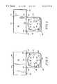
- FIG. 5is a top view of the square mounting tube welded in only two locations to the side frame member of the base frame showing the interior surface of the walls of the mounting tube formed to include partial cylindrical concave sections for receipt of the caster;
- FIG. 6is a bottom view of the square mounting tube of FIG. 5 showing a notch formed in the mounting tube for receiving a set screw of a caster;
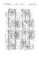
- FIG. 7is a partially broken away side view of the base frame of FIG. 2 showing hex rods from two different castors received in brake/steer brackets pivotally mounted near both ends of the brake/steer link, and two cross shafts each of which are pivotally coupled by a cross shaft link to an arm bracket attached to the brake/steer link;
- FIG. 8is a view similar to FIG. 7 showing the effect of rotation of either one of the hex shafts by approximately thirty degrees in the clockwise direction and also showing the effect of rotation of either one of the hex shafts by approximately thirty degrees in the counter-clockwise direction in phantom lines;
- FIG. 9is a side elevation view of the cross shaft of the present invention showing attachment holes near both ends of the cross shaft and medial holes (in phantom lines) extending through the cross shaft orthogonal to the attachment holes;
- FIG. 10is the cross shaft of FIG. 9 rotated ninety degrees about its longitudinal axis
- FIG. 11is front plan view of the cross shaft link of FIG. 7;
- FIG. 12is side view of the cross shaft link of FIG. 11;
- FIG. 13is a front plan view of the arm bracket of FIG. 7;
- FIG. 14is a side view of the arm bracket of FIG. 13;
- FIG. 15is a front plan view of the brake/steer bracket of FIG. 7;
- FIG. 16is a side view of the brake/steer bracket of FIG. 15;
- FIG. 17is an exploded view of a low profile caster, a side frame member of a base frame, and a square mounting tube for use with the braking system of the present invention
- FIG. 18is a partial cross sectional view of the assembled caster, side frame member, and square mounting tube of FIG. 17;
- FIG. 19is a view taken along line 19 — 19 of FIG. 18;
- FIG. 20is a perspective view of an alternative caster mounting tube and caster for use with the braking system of the bed, showing a brake/steer caster formed with a sleeve having a square cross-section portion and a square lumen and a spindle having a square cross section for receipt in the square lumen, and a mounting tube formed from square tube stock.
- hospital beds 20 for use in healthcare facilitiestypically include a mattress 22 located on an articulating deck 24 pivotally mounted to an intermediate frame 26 which is vertically adjustable relative to a weigh frame 27 connected to a base frame 28 .
- Base frame 28includes two spaced-apart longitudinally extending side frame members 32 connected by laterally extending cross members 68 , 70 .
- a caster mounting tube 38is typically welded to side frame member 32 as shown by weld beads 40 , in FIGS. 5-6.
- a sleeve 42 of a caster device 44is received in each of the caster mounting tubes 38 .
- the first type of caster device 44commonly called a brake/steer caster 46 , includes a mechanism therein to inhibit the rotation of the wheels of the caster (i.e. brake mechanisms 48 ) and a mechanism to prevent swiveling of the caster forks (i.e. anti-swivel or directional lock mechanisms 50 ), as shown, for example, diagrammatically in phantom lines in FIG. 4 .
- the second type of caster device 44commonly called a brake caster 52 , includes only a brake mechanism 48 .
- the anti-swivel mechanism 50 and brake mechanism 48are actuated through rotation of a hex shaft 54 .
- Hex shaft 54acts as a fulcrum of cantilevered brake/steer actuator 128 .
- brake pedal 56 and steer pedal 58Disposed on opposite sides of hex shaft 54 are brake pedal 56 and steer pedal 58 , both of which are operable by the foot of the caregiver.
- Each caster device 44preferably includes its own hex shaft 54 , brake pedal 56 , and steer pedal 58 regardless of whether the specific caster device 44 is a brake/steer caster 46 or a brake caster 52 , as shown, for example, in FIGS. 2-3.
- base frame 28includes a pair of spaced-apart side frame members 32 extending longitudinally along each side of bed 20 and a pair of cross members 68 , 70 extending laterally between, and connecting, the side frame members 32 .
- side frame members 32are rectangular tubes having a top surface 60 , a bottom surface 62 , an inside surface 64 , an outside surface 66 , head end 34 , and foot end 36 .
- Welded near head end 34 and foot end 36 to outside surface 66 of side frame member 32are square caster mounting tubes 38 for receipt of sleeves 42 of caster devices 44 .
- head end cross member 68 and foot end cross member 70are formed from a metal plate which is bent to form two spaced-apart sidewalls 72 extending downwardly from a top wall 74 .
- cross members 68 , 70include a first end 76 , a second end 78 , top wall 74 , and two spaced-apart downwardly extending sidewalls 72 .
- Top wall 74 at first end 76 of cross members 68 , 70is welded to the bottom surface 62 of side frame member 32 and top wall 74 of second end 78 of cross members 68 , 70 is welded to bottom surface 62 of second side frame member 32 .
- Square cross section caster mounting tubes 38include an outside wall 80 , an inside wall 82 , a front wall 84 , a rear wall 86 , an upper edge 88 , a lower edge 90 , an interior, and an exterior. As shown, for example, in FIGS. 5 and 6, inside wall 82 of caster mounting tube 38 contiguously engages outside surface 66 of side frame member 32 .
- Mounting tube 38is welded to side frame member 32 at the corner 92 formed by front wall 84 and inside wall 82 and at the corner 94 formed by rear wall 86 and inside wall 82 to outside surface 66 of side frame member 32 .
- Vertical axis of mounting tube 38extends substantially perpendicular to longitudinal axis of side frame member 32 .
- caster sleeves 42typically have a circular cross section
- the interior surface of each of inside wall 82 , outside wall 80 , front wall 84 , and rear wall 86are drilled, machined, bored, or otherwise formed to include partial cylindrical concave sections 93 , as shown for example in FIGS. 5-6, for receiving the sleeve 42 of the caster.
- corner notchesare residual portions of the internal square tube left after hollow square tube has been drilled out to form partial cylindrical concave sections 93 .
- Square cross section mounting tubes 38may be attached to base frame 28 using fewer parts and fewer operations than are required for attachment of standard tubes.
- Standard tubeshave circular cross-sections and cannot securely be welded directly to side frame members 32 .
- an intermediate bracketis typically welded in two locations to the standard tube and then the bracket is welded in two locations to side frame member 32 .
- Providing bed 20 with square mounting tubes 38eliminate eight welds and four parts from the assembly of a bed having four casters.
- caster mounting tubes 38are connected to the rectangular side frame member of bed 20 , it is within the teachings of the invention to mount caster mounting tubes 38 to any rectangular frame member of a patient support apparatus such as a bed, stretcher, chair, or the like. Attachment of caster mounting tubes 38 to a rectangular frame member can be accomplished with a two axis welding machine which is substantially cheaper than the four axis welding machine required to weld a standard tube and intermediate bracket to a frame member.
- the braking system 30 of the present inventionallows a caregiver to actuate the brake pedal 56 or steer pedal 58 of any of the caster devices 44 and thereby engage the brake mechanisms 48 or anti-swivel mechanisms 50 respectively of all of the caster devices 44 simultaneously.
- braking systemprovides both brake control and steer control.
- Illustrated braking system 30accomplishes simultaneous engagement of all braking mechanisms 48 or steering mechanisms 50 by mechanically linking the brake/steer actuators 128 of all of the caster devices 44 .
- the illustrated braking system 30mechanically links the hex shafts 54 of each caster device 44 so that rotation of one hex shaft 54 induces rotation of all of the hex shafts 54 .
- Shaft access holes 96are drilled or otherwise formed through outside wall 80 and inside wall 82 of mounting tube and outside surface 66 and inside surface 64 of side frame member 32 so that hex shaft 54 used to actuate the anti-swivel mechanism 50 and/or the brake mechanism 48 of caster device 44 may extend from the exterior of the mounting tube 38 through the interior of the side frame member 32 .
- a cap bushing 111is welded to the inside surface 64 of side frame member 32 at each caster 44 location. Hex shaft 54 extends into cap bushing 111 by receiving hex shaft 54 , cap bushing 111 acts to stabilize hex shaft 54 to minimize play in the brake/steer system 30 .
- a brake/steer link 98is disposed and extends longitudinally within the interior of side frame member 32 as shown, for example, in FIGS. 3, 4 , 7 , 8 and by phantom lines in FIGS. 2-3
- brake/steer link 98is formed from square metallic tubular material having a head end 100 , a foot end 102 , a top wall 104 , an outside side wall 106 , an inside side wall 108 , and a bottom wall 110 .
- Brake/steer brackets 112are pivotally mounted to brake/steer link 98 about pivot axis 114 near head end 100 and foot end 102 of brake/steer link 98 . As shown, for example, in FIGS.
- brake/steer link 98is formed to include a slot 115 through bottom wall 110 extending longitudinally from head end 100 and foot end 102 for a distance 117 sufficient to accommodate rotation of the brake/steer bracket 112 .
- distance 117is approximately 1.5′′.
- Rivet holes 116are formed in inside wall 108 and outside wall 106 of brake/steer link 98 adjacent the head end 100 and foot end 102 for receipt of a rivet 118 that acts as a pivot pin for brake/steer bracket 112 .
- brake/steer bracket 112is U-shaped having bottom member 120 extending between two spaced-apart apart arms 122 in which are formed pivot holes 124 through which rivet 118 extends and hexagonally-shaped shaft-receiving holes 126 through which the hex shaft 54 of the brake/steer actuator 128 is received.
- Brake/steer link 98is disposed within and free to move longitudinally and horizontally relative to side frame member 32 .
- the location of rotational axis 130 of hex shaft 54is fixed by shaft access holes 96 through which it extends. Therefore, rotation of hex shaft 54 causes brake/steer bracket 112 to rotate on rivet 118 causing brake/steer link 98 to move downward in an arc in the direction of rotation of the hex shaft 54 as shown by curved arrows 132 in FIG. 8 .
- clockwise rotationwhich is induced by stepping on the steer pedal 58 (typically color coded green) at the head end of bed 20 which is shown in solid lines in FIG. 8 .
- clockwise or counterclockwise rotation of the hex shaft 54 at the foot end 36 of bed 20will induce clockwise or counterclockwise rotation respectively of the hex shaft 54 at the head end of bed 20 .
- the brake/steer actuators 128 at the head end 34 or foot end 36 of one side of bed 20the brake mechanisms 48 and anti-swivel mechanisms 50 of the caster devices 44 at both ends of bed 20 will be actuated.
- cross shafts 134extend between each of the brake/steer links 98 .
- Welded, or otherwise appropriately connected, to the bottom of brake/steer link 98are U-shaped downwardly opening arm brackets 136 having a top plate 138 extending between spaced-apart inside arm 140 and outside arm 142 .
- Inside arm 140 and outside arm 142are formed to include rivet holes 144 for receipt of a rivet 146 .
- Each arm bracket 136is displaced from the rivet holes 116 in the end of brake/steer link 98 by a distance 148 equal to the distance 150 between hex shaft access hole 96 in side frame member 32 and the center of cross member 68 , 70 as shown, for example, in FIG. 7 .
- a cross shaft link 152 having a cylindrical housing 154 and a pivot flange 156 extending upwardly therefromis pivotally mounted to arm bracket 136 about pivot axis 158 .
- Pivot flange 156is formed to include a pivot hole 160 centered about pivot axis 158 .
- Rivet 146extends through rivet hole 144 and pivot hole 160 coupling cross shaft link 152 to arm bracket 136 in a manner allowing pivoting of cross shaft link 152 relative to arm bracket 136 .
- rivet 144is inserted through outside arm 138 of arm bracket 136 , a first cylindrical spacer 162 , pivot hole 160 of pivot flange 156 , a second cylindrical spacer 164 , and rivet hole 144 in inside arm 140 of arm bracket 136 so that cross shaft link 152 pivots relative to arm bracket 136 .
- Cylindrical housing 154has an inside diameter 166 sized to receive the outside diameter 168 of cross shaft 134 as shown, for example, in FIG. 4 .
- Diametrically opposed pin holes 170are formed in housing 154 of cross shaft link 152 to receive a rotation pin 172 .
- the axis of rotation 174 of cross shaft 134passes through the center of cylindrical housing 154 which is displaced from the pivot axis 158 of rivet 146 which passes through the center of pivot hole 160 by a displacement 176 .
- Displacement 176is equal to the displacement 178 between the pivot axis 114 of rivet 118 which passes through the center of pivot hole 124 and the rotational axis 130 of hex shaft 54 which passes through the center of hex shaft receiving hole 126 in brake/steer bracket 112 . Since rotation axis 130 of hex shaft 54 and axis of rotation 174 of cross shaft 134 are fixed in space relative to each other, rotation of hex shaft 54 by a specified number of degrees will induce rotation of cross shaft by the same number of degrees as indicated by slash marks 177 and 179 through curved arrows 132 and curved arrows 181 in FIG. 8 .
- Cross shaft 134extends between cross shaft link 152 on one side of bed 20 and the associated cross shaft link 152 on the other side of bed 20 .
- Cross shaft 134is received in the interior 180 of cross member 68 , 70 which is formed to include gussets 182 formed to include cylindrical holes 184 having an inside diameter 186 sized to receive the outside diameter 168 of the cross shaft 134 . It is the receipt of cross shaft 134 in these gussets 182 which fixes the axis of rotation 174 of the cross shaft 134 relative to the cross member 68 , 70 and base frame 28 .
- attachment holes 192are drilled or otherwise formed to extend diametrically through cross shaft 134 .
- Cross shaft 134is formed to include two medial holes 194 extending diametrically through cross shaft 134 orthogonal to the attachment holes 192 on the ends of cross shaft. Each medial hole 194 is displaced from its adjacent attachment hole 192 by a displacement 196 so that orientation of cross shaft 134 is not critical during assembly.
- Medial holes 194are designed to receive lever arms (not shown) which can actuate switches or sensors 198 (FIGS. 2, 3 ) connected to an indicator system (not shown) which indicates when the brake mechanisms 48 are engaged.
- access aperture 191is formed in bottom surface 62 of side frame member 32 .
- access aperture 193is formed in top wall 74 of cross member 68 , 70 .
- Access apertures 191 , 193have a length 195 sufficient to allow uninhibited rotation of hex shaft 54 through ninety degrees and the associated movement of arm bracket 136 and cross shaft link 152 as shown, for example, in FIG. 8 .
- First end 188 of cross shaft 134is received in the housing 154 of cross shaft link 152 so that pin receiving holes 170 in cross shaft link 134 and attachment holes 192 in cross shaft 134 are aligned and rotation pin 172 extends therethrough to fix cross shaft 134 to cross shaft housing 154 so that rotation of cross shaft housing 154 will induce rotation of the cross shaft 134 .
- Second end 190 of cross shaft 134is received in the cross shaft housing 154 associated with the brake/steer link 98 on the other side of bed 20 so that attachment hole 192 in cross shaft 134 and pin receiving pin hole 170 in cross shaft housing 154 are aligned and rotation pin 172 extends therethrough to fix cross shaft 134 relative to the housing 154 so that rotation of the shaft 134 will induce rotation of the housing 154 .
- the various links of the braking system 30induce the braking mechanisms 48 to be actuated in all of the other caster devices 44 .
- the links of braking system 30induce actuation of the anti-swivel mechanisms 50 in all of the other caster devices 44 equipped with such mechanisms.
- Brake mechanisms 48 and anti-swivel mechanisms 50 of caster devices 44 on opposite sides of the same end of a bedmay be connected by a single hex shaft (not shown) extending from the caster device 44 on one side of the bed to the caster device 44 on the opposite side of the bed.
- Rotation of extended hex shaftwill simultaneously rotate cams 53 in both caster devices 44 so that rotation of the extended hex shaft is directly translated to the caster 44 on the opposite side of the bed eliminating the need for the cross shaft 134 .
- the extended hex shaftmust extend through the caster stem 42 it is typically located above the bottom surface 62 of side frame member 32 . In certain beds, the extended hex shaft can interfere with the hi/lo operation of the bed.
- cross shaft 134is received in the interior of cross member 68 , 70 and therefore is not as likely to interfere with the hi/lo functions as an extended hex shaft because cross shaft 134 is located below the bottom surface 62 of side frame member 32 .
- caster devices 44 at head end of bed 20are brake/steer casters 46 .
- An example of a commonly available brake/steer caster 46is the caster from Tente-Rollen GmbH and Company, Part No. 2044UAP125R36-32S30.
- brake mechanism 48 and anti-swivel mechanism 50are represented diagrammatically in phantom lines in FIG. 4 . This diagrammatic representation is not intended to precisely depict the internal components of brake/steer casters as such components are known.
- Brake/steer casters 46include brake mechanisms 48 which are activated through counterclockwise rotation of a hex shaft 54 and anti-swivel mechanisms 50 which are activated by clockwise rotation of the hex shaft 54 .
- brake mechanisms 48which are activated through counterclockwise rotation of a hex shaft 54
- anti-swivel mechanisms 50which are activated by clockwise rotation of the hex shaft 54 .
- counter-clockwise and clockwiseare used to describe the rotation of hex shafts 54 , it should be understood that the terms are defined with reference to a caregiver on the near side (as shown in FIG. 1) of bed 20 facing toward the near side of bed 20 . It should also be understood that what appears to be clockwise rotation to a caregiver on the near side of bed 20 facing near side of bed 20 would appear to be counter-clockwise rotation to a caregiver on the far side of bed 20 facing the far side of bed 20 .
- Rotation of the hex shaft 54induces displacement of a spindle 49 which is disposed concentric to the swivel axis 47 of the caster wheel fork 51 .
- a cam 53is attached to the hex shaft 54 .
- Cam 53has a lobe (not shown) and an indentation (not shown) formed therein which induce displacement of spindle 49 , which acts as a follower, upon rotation of the hex shaft 54 .
- cam 53is in neutral position, in which the wheels are free to turn and the caster is free to swivel, when the arms 129 , 131 of brake/steer actuator 128 are parallel to the floor as in FIGS.
- caster devices 44 at foot end 36 of bed 20are brake casters 52 .
- An example of a commonly available brake caster 52is the caster from Tente-Rollen GmbH and Company, Part No. 2046UAP125R36-32S30.
- Brake casters 52while not illustrated are similar to brake/steer casters 46 shown in FIG. 4 except that brake casters 52 do not include anti-swivel mechanisms 50 .
- brake caster 52are used in conjunction with brake/steer casters 46 to facilitate steering of bed 20 during transportation of bed 20 . If brake casters 52 were used for all four caster devices 44 , steering of bed 20 would be very difficult. Combining brake/steer casters 46 with brake casters 52 allows the anti-swivel mechanisms 50 to be activated on the brake/steer casters 46 so that bed 20 can then be steered in the same fashion as the familiar shopping cart.
- Brake casters 52include brake mechanisms 48 which are activated through counterclockwise rotation of a hex shaft 54 but, because they do not include anti-swivel mechanisms 50 , the caster wheel 55 is always free to swivel.
- Rotation of the hex shaft 54induces displacement of a spindle 49 which is disposed concentric to the swivel axis 47 of the caster wheel fork 51 .
- cam 153is attached to the hex shaft 54 .
- Cam 153has a lobe (not shown) formed therein which induces displacement of spindle 49 , which acts as a follower, upon rotation of the hex shaft 54 .
- cam 153is in neutral position, in which the wheel 55 is free to turn and the caster is free to swivel, when the arms 129 , 13 1 of brake/steer actuator 128 are parallel to the floor as in FIGS. 1-4 and the brake/steer link 98 and brake/steer bracket 112 are in the position shown in FIG. 7 .
- Rotation of the hex shaft 54 counterclockwiseinduces cam 153 to rotate so that lobe displaces spindle 49 downward to engage braking mechanism 48 against the wheel 55 of the caster.
- Rotation of the hex shaft 54 clockwisecauses rotation of cam 153 so that spindle 49 rides off the lobe and brake mechanism 48 is disengaged.
- brake/steer caster 46 and brake caster 52are provided with a set screw 57 near the point of connection between sleeve 42 and caster fork 51 .
- Set screw 57is displaced 90° from hex shaft 54 .
- Mounting tube 38is formed to include a notch 59 formed in lower edge 90 of rear wall 86 .
- set screw 57is received in notch 59 as shown, for example in FIG. 4 .
- Set screw 57 and notch 59prevent rotation of sleeve 42 in mounting tube 38 which prevents binding of hex shaft 54 in shaft access holes 96 .
- braking system 30is described as using brake/steer casters 46 at the head end of bed 20 and brake casters 52 at the foot end 36 of bed 20 , it is to be understood that all caster devices 44 could be brake/steer casters 46 or brake casters 52 within the scope of the invention. Likewise any combination and configuration of brake casters 52 and brake/steer casters 46 mounted to a bed 20 employing braking system 30 is within the teaching of the invention.
- Intermediate frame 26is designed to be raised or lowered with respect to weigh frame 27 and base frame 28 using what is commonly called the hi/lo function of the bed 20 .
- the low profile casters 200 shown in FIGS. 17-19may be incorporated with braking system 30 instead of the caster devices 44 described above.
- Commonly available caster devices 44 including braking mechanisms 48typically have hex shaft 54 extending through sleeve 42 above the location of set screw as shown, for example, in FIG. 4 . This typical arrangement places hex shaft 54 substantially above the surface of the floor on which wheel 55 rests.
- hex shaft 54 and pedals 56 , 58 actuating hex shaft 54can interfere with the operation of the hi/lo mechanism which raises and lowers intermediate frame 26 with respect to the base frame 28 . Interference with the hi/lo function occurs only at the lower limit of the height adjustment, if at all.
- Low profile caster 200is designed for use with braking system 30 .
- Low profile caster 200may also be used in an alternative embodiment of braking system (not shown) wherein the cross shafts 134 are eliminated and extended hex shafts extend between casters at the same end but on opposite sides of bed 20 .
- Low profile caster 200includes a sleeve 242 formed from two half shells 242 a, 242 b attached to swivel with respect to a caster fork 251 to which two counter-rotatable wheels 255 a, 255 b are rotatably mounted.
- Half shells 242 a, 242 bare joined together with a first washer 204 having the inside diameter 205 substantially equal to the outside diameter 207 of the outside wall 206 at base 201 of the sleeve 242 and a second washer 208 having an inside diameter 209 substantially equal to the outside diameter 211 of the wall 210 of a recessed step 212 formed at the top edge 203 of the sleeve 242 .
- Half shells 242 a, 242 bare formed so that when joined they create a sleeve 242 having an interior, an exterior, and a height 297 .
- Height 297 of sleeveis related to the stability of the sleeve in the caster mounting tube 38 and to maximum stresses which sleeve can endure when received in mounting tube 38 . Up to a point, taller the sleeve 242 the more stable the sleeve 242 is when received in caster mounting tube 38 . Also taller sleeves can endure the more stress. However, stability and stress tolerance are not improved when sleeve height 297 exceeds caster mounting tube height.
- sleeve 42Interior of sleeve 42 is formed to have a cavity 213 for receipt of a cam 253 , a screw 214 , a spring 215 , and a pivot housing 216 .
- Sleeve 242is formed to include shaft holes 217 extending therethrough for receipt of the hex shaft 54 of a brake/steer actuator 128 .
- Cam 253includes a substantially cylindrical outer surface 218 which is deformed to include a lobe 219 and a longitudinal hexagonal opening 221 through which hex shaft 54 extends so that rotation of hex shaft 54 will induce rotation of cam 253 .
- Downwardly extended arms 223 of caster fork 253are formed to include axle holes 225 .
- Twin wheels 255 a, 255 b separated by a spacerare mounted for rotation relative to caster fork 253 by an axle 227 extending through both axle holes 225 , each wheel 255 a, 255 b, and the spacer separating the wheels 255 a, 255 b.
- Twin wheels 255 a, 255 b and spacerare arranged so that the inner side 229 of each wheel is displaced from the inner side 229 of the other wheel 255 b, 255 a by a displacement 231 .
- Caster fork 251includes a top surface 233 having a hole 235 therethrough sized to receive shaft of pivot housing 216 which is swedged between top surface 233 and bottom surface 237 of caster fork 251 .
- Bottom surface 237 of caster fork 251is formed to include a hole 295 through which hex spindle 248 extends.
- Pivot housing 216is formed to include a hexagonally shaped internal lumen 239 through which hex spindle 249 of an locking mechanism 248 extends. Locking mechanism 248 , when engaged simultaneously brakes the wheels 255 a and 255 b and inhibits swivelling of caster 200 as will be described hereafter.
- Hex spindle 249has a first end 241 which is tapped to receive screw 214 and a second end 243 to which a plunger wedge 245 is attached.
- Plunger wedge 245is designed to engage the wheels 255 a, 255 b of the caster 200 providing braking of the same.
- the hexagonal shape of the spindle 249 and internal lumen 239prevents rotation of hex spindle 249 and plunger wedge 245 to resist caster swivelling.
- Pivot housing 216has a body 261 having a flange 263 with a first diameter 265 and a top surface 267 which acts as a spring engaging face, a faceted hexagonal section 269 , and a lower flange 271 .
- Pivot housingalso includes a recessed shaft 237 and a flared portion 275 .
- Recessed shafthas a second diameter smaller than the first diameter and is sized to extend through the hole 235 in top surface 233 of caster fork 251 .
- Recessed shaft 273is connected at one end to body 261 and at the other end flared portion 275 of pivot housing 216 .
- Cavity 285 in interior of sleeve 242is formed to have a hexagonal cross-section and is sized to receive faceted hexagonal section 269 of pivot housing 216 . Receipt of the hexagonal section 269 in the hexagonal cavity 285 prevents pivot housing 216 from rotating relative to sleeve 242 . Rotation of sleeve 242 within mounting tube 238 is prevented by set screw 257 which passes through set screw hole in outside wall 280 of mounting tube 238 and is received in tapped screw hole 287 in sleeve 242 . Tapped screw hole 287 is located above shaft holes 217 in sleeve 242 and set screw hole 259 is located above shaft access hole 296 in mounting tube 38 .
- Screw 214acts as a follower and engages surface of cam 253 .
- plunger wedge 245does not engage the wheels 255 a, 255 b of caster 200 .
- Top flange 268 and bottom flange 271are received in channels 277 and 279 formed in interior of sleeve 242 respectively so that rotation of the cam 253 counterclockwise as shown by arrow 281 causes screw 214 to follow the lobe 219 and compress spring 215 between screw 214 and top surface 267 .
- Rotation of cam 253causes spindle 249 to move longitudinally as shown by arrow 283 within hexagonally shaped internal lumen 239 in pivot housing 216 until plunger wedge 245 is wedged between the wheels 255 a, 255 b of the caster 200 to prevent rotation of the wheels 255 a, 255 b and provide braking to the caster 200 . Since swiveling is facilitated by wheel 255 a rotating, in the opposite direction as wheel 255 b, when plunger wedge 245 is lodged between wheels 255 a, 255 b as shown in phantom lines in FIG. 18, swiveling of caster 200 is also inhibited. Clockwise rotation of hex shaft 54 from the brake position causes screw 214 to follow lobe 219 back onto the neutral surface 218 as spring 215 decompresses.
- Low profile caster 200is designed so that the displacement 289 between shaft holes 217 , and therefore hex rod 54 , and floor 291 upon which the caster wheels rest is less than five inches. As a result of this positioning, hex rod 254 will not inhibit adjustment of intermediate frame 26 relative to base frame 228 until intermediate frame 26 is substantially closer to the floor than the lowest position that it can achieve with a standard caster 44 .
- shaft holes 217are displaced from base 201 of by a displacement 295 which is less than half of height 297 of sleeve 242 .
- Caster 444includes a wheel 55 (not shown) rotatably mounted to a caster fork 51 (not shown) a brake pad 445 , an anti-swivel or directional locking mechanism 450 , a spindle 449 , a sleeve 442 formed to include a hex shaft-receiving hole 417 and being mounted to swivel with respect to caster fork 51 , a cam 53 (not shown) having a brake surface and a steer lock surface internally located in sleeve.
- Caster sleeveincludes a medial portion 541 having a square cross section, an upper portion 543 having a circular cross section, and a lower portion 545 having a circular cross section.
- Spindle 449includes a follower end 547 , an upper portion 549 having a circular cross extending between follower end 547 and a medial portion 551 having a square cross section, a lower portion 553 having a circular cross section extending between medial portion 551 and a connector end 555 .
- upper portion 549 and medial portion 551 of spindle 449is received in square lumen 439 of sleeve 442 with follower end 547 engaging cam 53 .
- Lower portion 553 of spindle 449extends through top surface 433 of caster fork 51 .
- Anti-swivel mechanism 50is received on lower portion 553 of spindle 449 and brake pad 445 is connected to connector end 555 .
- Square caster mounting tube 438is similar to square mounting tube 38 except that it does not include partial cylindrical concave sections 93 and thus includes an inner tube 557 having a square cross section for receipt of sleeve 442 .
- Square caster mounting tube 438is attached to side frame member 32 with two welds 40 extending along the corners formed by rear wall 486 and inside wall 482 and front wall 484 and inside wall 482 .
- Square caster mounting tube 438is formed to include shaft access holes 496 through outer and inner walls 482 , 480 .
- Sleeve 442is received in inner tube 557 of square caster mounting tube 438 so that hex shaft-receiving hole 417 is aligned with shaft access holes 496 and hex shaft 54 passes through both holes 417 , 496 and engages cam 53 in the interior of sleeve 442 .
- Operation of the brake and anti-swivel mechanism 448 , 450is similar to the operation previously disclosed. Because of the square cross sections of mounting tube 438 and sleeve 442 , sleeve 442 self aligns when received in inner tube 557 of mounting tube 438 eliminating the need for a set screw. Square lumen 439 and square cross section of medial portion 551 of spindle 449 prevent spindle 449 from spinning within the lumen 439 enhancing both brake and anti-swivel mechanism 448 , 450 operation.
Landscapes
- Engineering & Computer Science (AREA)
- Mechanical Engineering (AREA)
- Health & Medical Sciences (AREA)
- Life Sciences & Earth Sciences (AREA)
- Animal Behavior & Ethology (AREA)
- General Health & Medical Sciences (AREA)
- Public Health (AREA)
- Veterinary Medicine (AREA)
- Nursing (AREA)
- Invalid Beds And Related Equipment (AREA)
- Braking Arrangements (AREA)
- Handcart (AREA)
Abstract
Description
Claims (48)
Priority Applications (11)
| Application Number | Priority Date | Filing Date | Title |
|---|---|---|---|
| US09/263,039US6321878B1 (en) | 1999-03-05 | 1999-03-05 | Caster and braking system |
| BR0008752-1ABR0008752A (en) | 1999-03-05 | 2000-03-02 | Brake system for a hospital bed, patient support device, and process for attaching a caster to a bed base structure |
| AU41694/00AAU4169400A (en) | 1999-03-05 | 2000-03-02 | Caster and braking system |
| JP2000602477AJP4986326B2 (en) | 1999-03-05 | 2000-03-02 | Casters and braking systems |
| PCT/US2000/005406WO2000051830A1 (en) | 1999-03-05 | 2000-03-02 | Caster and braking system |
| ES00921358TES2240089T3 (en) | 1999-03-05 | 2000-03-02 | ROLDANA AND BRAKING SYSTEM. |
| CA002364064ACA2364064A1 (en) | 1999-03-05 | 2000-03-02 | Caster and braking system |
| EP00921358AEP1156936B1 (en) | 1999-03-05 | 2000-03-02 | Caster and braking system |
| AT00921358TATE295275T1 (en) | 1999-03-05 | 2000-03-02 | STEERING ROLLER AND BRAKE DEVICE |
| DE60020084TDE60020084T2 (en) | 1999-03-05 | 2000-03-02 | STEERING WHEEL AND BRAKING DEVICE |
| US09/992,455US20020033307A1 (en) | 1999-03-05 | 2001-11-26 | Hospital bed caster and braking system |
Applications Claiming Priority (1)
| Application Number | Priority Date | Filing Date | Title |
|---|---|---|---|
| US09/263,039US6321878B1 (en) | 1999-03-05 | 1999-03-05 | Caster and braking system |
Related Child Applications (1)
| Application Number | Title | Priority Date | Filing Date |
|---|---|---|---|
| US09/992,455DivisionUS20020033307A1 (en) | 1999-03-05 | 2001-11-26 | Hospital bed caster and braking system |
Publications (1)
| Publication Number | Publication Date |
|---|---|
| US6321878B1true US6321878B1 (en) | 2001-11-27 |
Family
ID=23000130
Family Applications (2)
| Application Number | Title | Priority Date | Filing Date |
|---|---|---|---|
| US09/263,039Expired - LifetimeUS6321878B1 (en) | 1999-03-05 | 1999-03-05 | Caster and braking system |
| US09/992,455AbandonedUS20020033307A1 (en) | 1999-03-05 | 2001-11-26 | Hospital bed caster and braking system |
Family Applications After (1)
| Application Number | Title | Priority Date | Filing Date |
|---|---|---|---|
| US09/992,455AbandonedUS20020033307A1 (en) | 1999-03-05 | 2001-11-26 | Hospital bed caster and braking system |
Country Status (10)
| Country | Link |
|---|---|
| US (2) | US6321878B1 (en) |
| EP (1) | EP1156936B1 (en) |
| JP (1) | JP4986326B2 (en) |
| AT (1) | ATE295275T1 (en) |
| AU (1) | AU4169400A (en) |
| BR (1) | BR0008752A (en) |
| CA (1) | CA2364064A1 (en) |
| DE (1) | DE60020084T2 (en) |
| ES (1) | ES2240089T3 (en) |
| WO (1) | WO2000051830A1 (en) |
Cited By (97)
| Publication number | Priority date | Publication date | Assignee | Title |
|---|---|---|---|---|
| WO2003020536A1 (en) | 2001-09-05 | 2003-03-13 | Hill-Rom Services, Inc | Hospital bed wheel linkage apparatus |
| WO2003028610A1 (en) | 2001-10-02 | 2003-04-10 | Hill-Rom Services, Inc. | Integrated barrier and fluid supply for a hospital bed |
| US6584641B1 (en)* | 1999-08-21 | 2003-07-01 | Tente-Rollen Gmbh & Co. | Brake and steering lock for castor |
| WO2003057126A1 (en) | 2002-01-04 | 2003-07-17 | Hill-Rom Services, Inc. | Braking apparatus for a patient support |
| US20030192725A1 (en)* | 1999-09-15 | 2003-10-16 | Heimbrock Richard H. | Stretcher having a motorized wheel |
| US6680443B2 (en) | 2001-06-22 | 2004-01-20 | Hill-Rom Services, Inc. | Load cell apparatus having a gap measuring device |
| US20040011597A1 (en)* | 2000-11-21 | 2004-01-22 | Walsh Thomas Donal | Trolley wheel mechanism |
| US20040128766A1 (en)* | 2002-10-25 | 2004-07-08 | Brian Freeborn | Adjustable bed carriage |
| US20040139545A1 (en)* | 2003-01-22 | 2004-07-22 | Reinke Christian H. | Side and end brake/steer mechanism for stretchers |
| WO2004080363A2 (en) | 2003-03-11 | 2004-09-23 | Carroll Hospital Group Inc. | Steerable ultra-low patient bed |
| US20040194221A1 (en)* | 2003-04-04 | 2004-10-07 | Ralph Thompson | Directional lock |
| US6865775B2 (en) | 2001-09-05 | 2005-03-15 | Hill-Rom Services, Inc. | Hospital bed caster apparatus |
| GB2407488A (en)* | 2003-10-28 | 2005-05-04 | Colson Castors Ltd | Castor |
| US20050091747A1 (en)* | 2002-10-25 | 2005-05-05 | M.C. Healthcare Products Inc. | Adjustable bed carriage |
| USD505365S1 (en) | 2002-10-10 | 2005-05-24 | M.C. Healthcare Products Inc. | Adjustable bed carriage |
| US20060010643A1 (en)* | 2004-07-15 | 2006-01-19 | Hornbach David W | Caster with powered brake |
| USD514478S1 (en) | 2003-10-21 | 2006-02-07 | M.C. Healthcare Products Inc. | Adjustable bed carriage |
| US20060059814A1 (en)* | 2004-09-13 | 2006-03-23 | Metz Darrell L | Load cell to frame interface for hospital bed |
| USD520783S1 (en) | 2004-10-01 | 2006-05-16 | M.C. Healthcare Products Inc. | Rotating assist rail |
| US7100222B2 (en) | 2001-08-22 | 2006-09-05 | Hill-Rom Services, Inc. | Apparatus and method for mounting hospital bed accessories |
| US20060195986A1 (en)* | 2005-03-07 | 2006-09-07 | Reza Hakamiun | Footboard for a hospital bed |
| US20070017029A1 (en)* | 2005-04-06 | 2007-01-25 | Wurdeman Byron W | Hospital beds with a rotating sleep surface that can translate into a chair configuration |
| WO2007010229A1 (en) | 2005-07-20 | 2007-01-25 | Huntleigh Technology Limited | Bed castor and brake assembly |
| GB2428375A (en)* | 2005-07-20 | 2007-01-31 | Huntleigh Technology Plc | Pedal for braking mechanism |
| US20070044272A1 (en)* | 2005-08-31 | 2007-03-01 | Siemens Medical Solutions Usa, Inc. | Activation mechanism for a locking mechanism of a caster |
| US20070056141A1 (en)* | 2005-09-15 | 2007-03-15 | Sergio Armano | Powered locking caster wheel |
| US7222377B2 (en) | 2001-08-22 | 2007-05-29 | Hill-Rom Services, Inc. | Apparatus and method for closing hospital bed gaps |
| US20070151027A1 (en)* | 2003-05-21 | 2007-07-05 | Hill Rom Services Inc | Hospital bed |
| US20070170673A1 (en)* | 2006-01-19 | 2007-07-26 | Hill-Rom Services, Inc. | Stretcher having hand actuated caster braking apparatus |
| US20070180616A1 (en)* | 2006-02-08 | 2007-08-09 | Hill-Rom Services, Inc. | User module for a patient support |
| US7296312B2 (en) | 2002-09-06 | 2007-11-20 | Hill-Rom Services, Inc. | Hospital bed |
| US20080092329A1 (en)* | 2006-10-20 | 2008-04-24 | Haion Caster Industrial Co., Ltd. | Wheel Assembly |
| US20080115324A1 (en)* | 2004-07-21 | 2008-05-22 | Wolfgang Block | Caster Having A Running Wheel |
| US20080120810A1 (en)* | 2005-11-17 | 2008-05-29 | Hill-Rom Services, Inc. | Hospital bed caster control system |
| US20080229545A1 (en)* | 2007-03-19 | 2008-09-25 | Jean-Bernard Duvert | Bed immobilization system integrated into chassis feet |
| US20080263771A1 (en)* | 2007-04-27 | 2008-10-30 | Hill-Rom Services, Inc. | Endboard for a patient support |
| US20080283329A1 (en)* | 2000-05-11 | 2008-11-20 | John David Vogel | Motorized traction device for a patient support |
| US20090000834A1 (en)* | 2005-12-16 | 2009-01-01 | Enrico Carletti | Device for the Assisted Loading of Stretcher |
| US7523515B2 (en) | 1995-01-03 | 2009-04-28 | Hill-Rom Services, Inc. | Hospital bed and mattress having a retractable foot section |
| US7574850B1 (en) | 2008-06-10 | 2009-08-18 | Deere & Company | Caster wheel locking system for walk-behind mower |
| US7922183B2 (en) | 2006-01-19 | 2011-04-12 | Hill-Rom Services, Inc. | Stretcher having hand actuated wheel braking apparatus |
| US20110113562A1 (en)* | 2009-11-16 | 2011-05-19 | Uzzle Thomas E | Endboard for person support apparatus |
| US20110120815A1 (en)* | 2005-11-10 | 2011-05-26 | Zbynek Frolik | Braking System for Patient Support |
| US20110131725A1 (en)* | 2009-12-09 | 2011-06-09 | Kci Licensing, Inc. | Patient support system with modular integrated fluid supply system |
| US7978084B2 (en) | 1999-03-05 | 2011-07-12 | Hill-Rom Services, Inc. | Body position monitoring system |
| US20110225767A1 (en)* | 2010-10-19 | 2011-09-22 | Gerald Taylor | Wheeling device for a packaged article |
| EP2460503A2 (en) | 2010-12-06 | 2012-06-06 | Hill-Rom Services, Inc. | Biometric bed configuration |
| EP2460504A2 (en) | 2010-12-06 | 2012-06-06 | Hill-Rom Services, Inc. | Retractable foot caster supports |
| EP2484329A2 (en) | 2011-02-08 | 2012-08-08 | Hill-Rom Services, Inc. | Brake pedal mechanism for hospital bed |
| US8286282B2 (en) | 1995-08-04 | 2012-10-16 | Hill-Rom Services, Inc. | Bed frame and mattress synchronous control |
| US8344860B2 (en) | 2004-08-02 | 2013-01-01 | Hill-Rom Services, Inc. | Patient support apparatus alert system |
| US8432287B2 (en) | 2010-07-30 | 2013-04-30 | Hill-Rom Services, Inc. | Apparatus for controlling room lighting in response to bed exit |
| US8464380B2 (en) | 2005-07-08 | 2013-06-18 | Hill-Rom Services, Inc. | Patient support apparatus having alert light |
| US20130160237A1 (en)* | 2011-12-23 | 2013-06-27 | Caremed Supply Inc. | Power-operated caster brake mechanism |
| US8484802B1 (en)* | 2012-01-11 | 2013-07-16 | Sunny Castors Co., Ltd. | Combination castor whose castor assemblies are braked and positioned simultaneously |
| US8522379B2 (en) | 2010-11-15 | 2013-09-03 | Hill-Rom Services, Inc. | Hospital bed foot section with caster cutouts |
| US8537008B2 (en) | 2008-09-19 | 2013-09-17 | Hill-Rom Services, Inc. | Bed status indicators |
| US20130282234A1 (en)* | 2012-04-23 | 2013-10-24 | Timothy J. Roberts | High centering bases for hospital gurneys |
| US20140103677A1 (en)* | 2008-11-07 | 2014-04-17 | Matunaga Manufactory Co., Ltd. | Six-wheeled stretcher |
| US9005101B1 (en) | 2014-01-04 | 2015-04-14 | Julian Van Erlach | Smart surface biological sensor and therapy administration |
| US9009893B2 (en) | 1999-12-29 | 2015-04-21 | Hill-Rom Services, Inc. | Hospital bed |
| US9089459B2 (en) | 2013-11-18 | 2015-07-28 | Völker GmbH | Person support apparatus |
| US9132053B1 (en)* | 2014-06-06 | 2015-09-15 | UMF Medical | Retractable wheel base |
| US20150259930A1 (en)* | 2012-08-21 | 2015-09-17 | Michael Wayne Strickland | Installation Assist and Method |
| EP3058869A1 (en) | 2015-02-18 | 2016-08-24 | Allen Medical Systems, Inc. | Monitoring a patient's state to control the patient support |
| US9572735B2 (en) | 2013-03-15 | 2017-02-21 | Kap Medical, Inc. | Bed systems and method |
| US9603764B2 (en) | 2014-02-11 | 2017-03-28 | Medline Industries, Inc. | Method and apparatus for a locking caster |
| US9655798B2 (en) | 2013-03-14 | 2017-05-23 | Hill-Rom Services, Inc. | Multi-alert lights for hospital bed |
| US20170144481A1 (en)* | 2015-11-20 | 2017-05-25 | Barbara Dunston | Chair Lock System |
| CN106806076A (en)* | 2017-01-23 | 2017-06-09 | 河北普康医疗设备有限公司 | The synchronous brake that a kind of medical sickbed is used |
| US9700247B2 (en) | 2012-03-21 | 2017-07-11 | Hill-Rom Services, Inc. | Patient support apparatus with redundant identity verification |
| US9833366B2 (en) | 2012-09-18 | 2017-12-05 | Stryker Corporation | Powered patient support apparatus |
| US9844868B1 (en) | 2014-01-27 | 2017-12-19 | Kenneth Robert Abbey | Cart system for tool manipulation |
| US20180051762A1 (en)* | 2016-08-16 | 2018-02-22 | Hill-Rom Services, Inc. | Inaccuracy Tolerant Actuation Assembly, Article Using the Same, and Method of Producing the Article |
| US10004651B2 (en) | 2012-09-18 | 2018-06-26 | Stryker Corporation | Patient support apparatus |
| US10052249B2 (en) | 2004-10-29 | 2018-08-21 | Stryker Corporation | Patient support with improved control |
| US10206836B2 (en) | 2011-11-11 | 2019-02-19 | Hill-Rom Services, Inc. | Bed exit alerts for person support apparatus |
| US10219958B2 (en) | 2014-11-13 | 2019-03-05 | Kap Medical, Inc. | Bed systems and methods |
| US10245886B2 (en) | 2015-10-07 | 2019-04-02 | Stryker Corporation | Person support apparatus with braking system |
| US10322045B1 (en)* | 2013-05-29 | 2019-06-18 | Paul Cuneo | Footboard for hospital bed with therapeutic mechanisms housed within |
| US20190350780A1 (en)* | 2018-05-21 | 2019-11-21 | Hill-Rom Services, Inc. | Patient support apparatus adaptable to multiple modes of transport |
| US10555860B2 (en)* | 2013-07-09 | 2020-02-11 | Eschmann Holdings Limited | Surgical tables |
| US10568792B2 (en) | 2015-10-28 | 2020-02-25 | Stryker Corporation | Systems and methods for facilitating movement of a patient transport apparatus |
| US10603234B2 (en) | 2016-03-30 | 2020-03-31 | Stryker Corporation | Patient support apparatuses with drive systems |
| US10806653B2 (en) | 2017-12-21 | 2020-10-20 | Stryker Corporation | Patient transport apparatus with electro-mechanical braking system |
| US10857833B2 (en) | 2018-05-23 | 2020-12-08 | Stryker Corporation | Caster assembly with brake assembly having low actuation force |
| US20210170791A1 (en)* | 2019-12-04 | 2021-06-10 | GE Precision Healthcare LLC | Ergonomic Central Wheel Lock for Ultrasound Consoles |
| US11197791B2 (en)* | 2018-11-21 | 2021-12-14 | Stryker Corporation | Patient transport apparatus with cable connected brake and steer lock assemblies |
| US11229565B2 (en) | 2018-05-21 | 2022-01-25 | Stryker Corporation | Pedal assembly for a patient support apparatus |
| US11246776B2 (en) | 2005-12-19 | 2022-02-15 | Stryker Corporation | Patient support with improved control |
| US11324648B2 (en)* | 2018-11-21 | 2022-05-10 | Stryker Corporation | Patient transport apparatus with steer lock assembly |
| WO2022272250A1 (en)* | 2021-06-21 | 2022-12-29 | BendPak, Inc. | Agile mobile scissor lift apparatus |
| US20240016686A1 (en)* | 2022-07-13 | 2024-01-18 | Dominion Investments LLC | Medical cart for use in patient care |
| WO2024046381A1 (en)* | 2022-09-02 | 2024-03-07 | 广州医软智能科技有限公司 | Hospital bed braking apparatus |
| US20240139050A1 (en)* | 2022-10-27 | 2024-05-02 | Stryker Corporation | Patient Support Apparatus Having A Skirt Barrier |
| US12053423B2 (en) | 2019-12-30 | 2024-08-06 | Stryker Corporation | Patient transport apparatus with electro-mechanical braking system |
| US12377680B2 (en)* | 2022-10-07 | 2025-08-05 | Catis Pacific Mfg. Corp. Ltd. | Caster with a circularly positioning structure |
Families Citing this family (19)
| Publication number | Priority date | Publication date | Assignee | Title |
|---|---|---|---|---|
| CN1899233A (en) | 2000-05-11 | 2007-01-24 | 希尔-罗姆服务股份有限公司 | Motorized traction device for a patient support |
| US7018157B2 (en) | 2001-09-20 | 2006-03-28 | Hill-Rom Services, Inc. | Powered transport apparatus for a bed |
| DE10200408C1 (en)* | 2002-01-08 | 2003-07-10 | Hans-Peter Barthelt | Rotating bed with improved stability |
| FR2836375B1 (en)* | 2002-02-28 | 2004-12-17 | Hill Rom Sas | DEVICE FRAME FOR MEDICAL OR PARAMEDICAL USE OF A PERSON'S ROLLING SUPPORT, WITH EASILY REMOVABLE CASTERS, AND DEVICE THUS EQUIPPED |
| US7073219B2 (en) | 2004-01-06 | 2006-07-11 | Teknion Concept | Side rail, hospital bed including the same, method of operating associated thereto and kit for assembling the side rail |
| FR2930922B1 (en) | 2008-05-06 | 2010-06-11 | Medicatlantic Sa | BRAKE SYSTEM FOR BED ON CASTERS |
| GB2471659A (en)* | 2009-07-04 | 2011-01-12 | Smirthwaite Ltd | Braking system for mobility device |
| CN102470695B (en)* | 2009-07-16 | 2014-07-16 | 株式会社南星 | Pedal structure |
| CN102442334B (en)* | 2010-10-09 | 2016-04-20 | 深圳迈瑞生物医疗电子股份有限公司 | A kind of central control brake system and trolley type movable medical equipment |
| US8418315B1 (en)* | 2012-01-11 | 2013-04-16 | Sunny Castors Co., Ltd. | Combination castor brake system whose castor assemblies are braked and positioned simultaneously |
| US8516656B2 (en)* | 2012-01-11 | 2013-08-27 | Sunny Castors Co., Ltd. | Combination castor whose castor units are braked simultaneously |
| JP5236821B1 (en)* | 2012-01-14 | 2013-07-17 | 商尼製輪實業股▲ふん▼有限公司 | Wheel braking mechanism |
| US9707143B2 (en) | 2012-08-11 | 2017-07-18 | Hill-Rom Services, Inc. | Person support apparatus power drive system |
| US10232667B2 (en)* | 2015-02-12 | 2019-03-19 | Nansin Co., Ltd. | Mounting structure for caster |
| JP6603046B2 (en)* | 2015-05-28 | 2019-11-06 | ジー・オー・ピー株式会社 | Transport cart |
| CN107854139B (en)* | 2017-12-14 | 2023-09-29 | 无锡祥生医疗科技股份有限公司 | Cart type medical ultrasonic diagnostic device |
| JP7121394B2 (en)* | 2018-08-27 | 2022-08-18 | 学校法人 久留米大学 | mobile bed |
| CN110370864B (en)* | 2019-07-22 | 2024-06-21 | 宁波科盛万向轮有限公司 | Central control medical wheel |
| JP6882796B2 (en)* | 2019-10-10 | 2021-06-02 | ジー・オー・ピー株式会社 | Transport trolley |
Citations (36)
| Publication number | Priority date | Publication date | Assignee | Title |
|---|---|---|---|---|
| US2659927A (en) | 1951-09-08 | 1953-11-24 | Easy Washing Machine Corp | Leg and caster mount |
| US2738539A (en) | 1953-06-05 | 1956-03-20 | Nagel Chase Mfg Company | Caster bracket |
| US3452386A (en) | 1967-02-27 | 1969-07-01 | Keystone Consolidated Ind Inc | Caster socket assembly |
| US3478381A (en) | 1966-11-07 | 1969-11-18 | Nagel Chase Mfg Co | Caster bracket device |
| US3479681A (en) | 1967-01-25 | 1969-11-25 | Louis Maslow | Caster assembly |
| US3487495A (en) | 1967-04-26 | 1970-01-06 | Nagel Chase Mfg Co | Caster assembly |
| US3705438A (en) | 1970-04-29 | 1972-12-12 | Firm Tente Rollen Gmbh Compani | Locable runners |
| US3879796A (en) | 1973-10-23 | 1975-04-29 | Standex Int Corp | Bed stabilizing assembly |
| CH570802A5 (en) | 1973-03-21 | 1975-12-31 | Bremshey Ag | Castor wheel locking system for hospital bed - foot pedal actuated lever system braking all wheels |
| US3988800A (en) | 1974-05-08 | 1976-11-02 | Albert Schulte Sohne Kg | Caster for furniture and the like |
| US4077087A (en) | 1976-12-10 | 1978-03-07 | Quick-Set, Incorporated | Caster and brake assembly |
| US4095532A (en) | 1976-03-15 | 1978-06-20 | Schering Aktiengesellschaft | Workplace equipment |
| US4175783A (en) | 1978-02-06 | 1979-11-27 | Pioth Michael J | Stretcher |
| US4190002A (en) | 1976-03-15 | 1980-02-26 | Schering, A.G. | Workplace equipment |
| US4385414A (en) | 1980-10-06 | 1983-05-31 | Joerns Furniture Company | Caster for adjustable beds and the like |
| US4414702A (en) | 1981-05-16 | 1983-11-15 | Firm Tente-Rollen Gesellschaft Mit Beschrankter Haftung Compagnie | Castor locking device for arresting the rotation and the swivelling of the castor |
| US4526253A (en)* | 1982-12-02 | 1985-07-02 | Lermer Apparatebau Gmbh | Brake for rollable receiving elements utilized particularly in airplanes |
| US4677706A (en) | 1984-06-21 | 1987-07-07 | Colson Castors (Europe) Limited | Castor brake |
| US4722114A (en) | 1985-09-06 | 1988-02-02 | Tente-Rollen Gmbh & Co. | Caster device |
| US4723808A (en) | 1984-07-02 | 1988-02-09 | Colson Equipment Inc. | Stretcher foot pedal mechanical linkage system |
| US4788741A (en) | 1987-07-17 | 1988-12-06 | Hilborn Robert R | Keyed mounting assembly for lockable swivel caster |
| US4815161A (en) | 1987-01-22 | 1989-03-28 | Skf Transportwielen B.V. | Swiveling wheel |
| US5014391A (en) | 1989-01-13 | 1991-05-14 | Arnolf Schulte | Lockable caster wheel |
| US5129218A (en) | 1991-01-23 | 1992-07-14 | N-R Industries, Inc. | Vehicle for use on flat or sloped surfaces |
| US5139116A (en) | 1990-02-06 | 1992-08-18 | Screen Stafford T | Castor with brake mechanism |
| US5184373A (en) | 1990-12-22 | 1993-02-09 | Albert Schulte Sohne Gmbh & Co. | Caster with conductors between the tire of its wheel and the carrier of its wheel frame |
| US5203149A (en) | 1991-01-23 | 1993-04-20 | N-R Industries, Inc. | Slope mower |
| US5242035A (en) | 1990-11-06 | 1993-09-07 | Albert Schulte Sohne Gmbh. & Co. | Caster with pivotable two-armed wheel brake |
| US5279010A (en) | 1988-03-23 | 1994-01-18 | American Life Support Technology, Inc. | Patient care system |
| US5303450A (en) | 1991-11-16 | 1994-04-19 | Albert Schulte Sohne Gmbh & Co. | Caster for use on mobile hospital beds and the like |
| US5330064A (en) | 1993-04-29 | 1994-07-19 | Hall Donald M | Support assembly for a holding rack |
| US5377372A (en) | 1993-03-31 | 1995-01-03 | Hill-Rom Company, Inc. | Hospital bed castor control mechanism |
| US5503416A (en) | 1994-03-10 | 1996-04-02 | Oec Medical Systems, Inc. | Undercarriage for X-ray diagnostic equipment |
| US5634532A (en)* | 1994-04-21 | 1997-06-03 | Bucher Management Ag | Brake system for traveling container |
| US5737801A (en) | 1996-11-12 | 1998-04-14 | Flood; William R. | Channel members |
| US5774936A (en) | 1994-04-13 | 1998-07-07 | Tente-Rollen Gmbh & Co. | Roller, in particular a castor |
Family Cites Families (10)
| Publication number | Priority date | Publication date | Assignee | Title |
|---|---|---|---|---|
| JPS4820219Y1 (en)* | 1970-04-03 | 1973-06-11 | ||
| JPS5027747Y2 (en)* | 1971-09-16 | 1975-08-16 | ||
| US5310482A (en)* | 1989-09-29 | 1994-05-10 | Sather Stanley H | Pulp dryer screen assembly and method for tightening the screen thereof |
| JPH0431103A (en)* | 1990-05-28 | 1992-02-03 | Paramount Bed Co Ltd | Lock operation mechanism for caster |
| JP2592716B2 (en)* | 1990-09-17 | 1997-03-19 | ハンマーキャスター株式会社 | Caster braking mechanism |
| JPH0822643B2 (en)* | 1991-09-20 | 1996-03-06 | パラマウントベッド株式会社 | Electric / manual combined caster interlocking lock operation mechanism |
| JPH0822645B2 (en)* | 1991-09-30 | 1996-03-06 | パラマウントベッド株式会社 | Interlocking lock mechanism for casters in beds, etc. |
| JP2670751B2 (en)* | 1994-08-26 | 1997-10-29 | パラマウントベッド株式会社 | Steering caster system for beds |
| JPH1071803A (en)* | 1996-08-30 | 1998-03-17 | Sekisui Chem Co Ltd | Transporation container equipped with braking mechanism |
| JPH1148704A (en)* | 1997-08-08 | 1999-02-23 | Futaba Kinzoku Kogyo Kk | Caster having brake mechanism |
- 1999
- 1999-03-05USUS09/263,039patent/US6321878B1/ennot_activeExpired - Lifetime
- 2000
- 2000-03-02EPEP00921358Apatent/EP1156936B1/ennot_activeExpired - Lifetime
- 2000-03-02ATAT00921358Tpatent/ATE295275T1/ennot_activeIP Right Cessation
- 2000-03-02ESES00921358Tpatent/ES2240089T3/ennot_activeExpired - Lifetime
- 2000-03-02JPJP2000602477Apatent/JP4986326B2/ennot_activeExpired - Lifetime
- 2000-03-02CACA002364064Apatent/CA2364064A1/ennot_activeAbandoned
- 2000-03-02AUAU41694/00Apatent/AU4169400A/ennot_activeAbandoned
- 2000-03-02DEDE60020084Tpatent/DE60020084T2/ennot_activeExpired - Fee Related
- 2000-03-02WOPCT/US2000/005406patent/WO2000051830A1/enactiveIP Right Grant
- 2000-03-02BRBR0008752-1Apatent/BR0008752A/ennot_activeApplication Discontinuation
- 2001
- 2001-11-26USUS09/992,455patent/US20020033307A1/ennot_activeAbandoned
Patent Citations (36)
| Publication number | Priority date | Publication date | Assignee | Title |
|---|---|---|---|---|
| US2659927A (en) | 1951-09-08 | 1953-11-24 | Easy Washing Machine Corp | Leg and caster mount |
| US2738539A (en) | 1953-06-05 | 1956-03-20 | Nagel Chase Mfg Company | Caster bracket |
| US3478381A (en) | 1966-11-07 | 1969-11-18 | Nagel Chase Mfg Co | Caster bracket device |
| US3479681A (en) | 1967-01-25 | 1969-11-25 | Louis Maslow | Caster assembly |
| US3452386A (en) | 1967-02-27 | 1969-07-01 | Keystone Consolidated Ind Inc | Caster socket assembly |
| US3487495A (en) | 1967-04-26 | 1970-01-06 | Nagel Chase Mfg Co | Caster assembly |
| US3705438A (en) | 1970-04-29 | 1972-12-12 | Firm Tente Rollen Gmbh Compani | Locable runners |
| CH570802A5 (en) | 1973-03-21 | 1975-12-31 | Bremshey Ag | Castor wheel locking system for hospital bed - foot pedal actuated lever system braking all wheels |
| US3879796A (en) | 1973-10-23 | 1975-04-29 | Standex Int Corp | Bed stabilizing assembly |
| US3988800A (en) | 1974-05-08 | 1976-11-02 | Albert Schulte Sohne Kg | Caster for furniture and the like |
| US4095532A (en) | 1976-03-15 | 1978-06-20 | Schering Aktiengesellschaft | Workplace equipment |
| US4190002A (en) | 1976-03-15 | 1980-02-26 | Schering, A.G. | Workplace equipment |
| US4077087A (en) | 1976-12-10 | 1978-03-07 | Quick-Set, Incorporated | Caster and brake assembly |
| US4175783A (en) | 1978-02-06 | 1979-11-27 | Pioth Michael J | Stretcher |
| US4385414A (en) | 1980-10-06 | 1983-05-31 | Joerns Furniture Company | Caster for adjustable beds and the like |
| US4414702A (en) | 1981-05-16 | 1983-11-15 | Firm Tente-Rollen Gesellschaft Mit Beschrankter Haftung Compagnie | Castor locking device for arresting the rotation and the swivelling of the castor |
| US4526253A (en)* | 1982-12-02 | 1985-07-02 | Lermer Apparatebau Gmbh | Brake for rollable receiving elements utilized particularly in airplanes |
| US4677706A (en) | 1984-06-21 | 1987-07-07 | Colson Castors (Europe) Limited | Castor brake |
| US4723808A (en) | 1984-07-02 | 1988-02-09 | Colson Equipment Inc. | Stretcher foot pedal mechanical linkage system |
| US4722114A (en) | 1985-09-06 | 1988-02-02 | Tente-Rollen Gmbh & Co. | Caster device |
| US4815161A (en) | 1987-01-22 | 1989-03-28 | Skf Transportwielen B.V. | Swiveling wheel |
| US4788741A (en) | 1987-07-17 | 1988-12-06 | Hilborn Robert R | Keyed mounting assembly for lockable swivel caster |
| US5279010A (en) | 1988-03-23 | 1994-01-18 | American Life Support Technology, Inc. | Patient care system |
| US5014391A (en) | 1989-01-13 | 1991-05-14 | Arnolf Schulte | Lockable caster wheel |
| US5139116A (en) | 1990-02-06 | 1992-08-18 | Screen Stafford T | Castor with brake mechanism |
| US5242035A (en) | 1990-11-06 | 1993-09-07 | Albert Schulte Sohne Gmbh. & Co. | Caster with pivotable two-armed wheel brake |
| US5184373A (en) | 1990-12-22 | 1993-02-09 | Albert Schulte Sohne Gmbh & Co. | Caster with conductors between the tire of its wheel and the carrier of its wheel frame |
| US5203149A (en) | 1991-01-23 | 1993-04-20 | N-R Industries, Inc. | Slope mower |
| US5129218A (en) | 1991-01-23 | 1992-07-14 | N-R Industries, Inc. | Vehicle for use on flat or sloped surfaces |
| US5303450A (en) | 1991-11-16 | 1994-04-19 | Albert Schulte Sohne Gmbh & Co. | Caster for use on mobile hospital beds and the like |
| US5377372A (en) | 1993-03-31 | 1995-01-03 | Hill-Rom Company, Inc. | Hospital bed castor control mechanism |
| US5330064A (en) | 1993-04-29 | 1994-07-19 | Hall Donald M | Support assembly for a holding rack |
| US5503416A (en) | 1994-03-10 | 1996-04-02 | Oec Medical Systems, Inc. | Undercarriage for X-ray diagnostic equipment |
| US5774936A (en) | 1994-04-13 | 1998-07-07 | Tente-Rollen Gmbh & Co. | Roller, in particular a castor |
| US5634532A (en)* | 1994-04-21 | 1997-06-03 | Bucher Management Ag | Brake system for traveling container |
| US5737801A (en) | 1996-11-12 | 1998-04-14 | Flood; William R. | Channel members |
Cited By (218)
| Publication number | Priority date | Publication date | Assignee | Title |
|---|---|---|---|---|
| US7523515B2 (en) | 1995-01-03 | 2009-04-28 | Hill-Rom Services, Inc. | Hospital bed and mattress having a retractable foot section |
| US8286282B2 (en) | 1995-08-04 | 2012-10-16 | Hill-Rom Services, Inc. | Bed frame and mattress synchronous control |
| US7978084B2 (en) | 1999-03-05 | 2011-07-12 | Hill-Rom Services, Inc. | Body position monitoring system |
| US8400311B2 (en) | 1999-03-05 | 2013-03-19 | Hill-Rom Services, Inc. | Hospital bed having alert light |
| US8830070B2 (en) | 1999-03-05 | 2014-09-09 | Hill-Rom Services, Inc. | Hospital bed having alert light |
| US8258963B2 (en) | 1999-03-05 | 2012-09-04 | Hill-Rom Services, Inc. | Body position monitoring system |
| US8525682B2 (en) | 1999-03-05 | 2013-09-03 | Hill-Rom Services, Inc. | Hospital bed having alert light |
| US6584641B1 (en)* | 1999-08-21 | 2003-07-01 | Tente-Rollen Gmbh & Co. | Brake and steering lock for castor |
| US8397846B2 (en) | 1999-09-15 | 2013-03-19 | Hill-Rom Services, Inc. | Patient support apparatus with powered wheel |
| US8240410B2 (en)* | 1999-09-15 | 2012-08-14 | Hill-Rom Services, Inc. | Patient support apparatus with powered wheel |
| US20030192725A1 (en)* | 1999-09-15 | 2003-10-16 | Heimbrock Richard H. | Stretcher having a motorized wheel |
| US6902019B2 (en)* | 1999-09-15 | 2005-06-07 | Hill-Rom Services, Inc. | Stretcher having a motorized wheel |
| US9009893B2 (en) | 1999-12-29 | 2015-04-21 | Hill-Rom Services, Inc. | Hospital bed |
| US10251797B2 (en) | 1999-12-29 | 2019-04-09 | Hill-Rom Services, Inc. | Hospital bed |
| US8267206B2 (en) | 2000-05-11 | 2012-09-18 | Hill-Rom Services, Inc. | Motorized traction device for a patient support |
| US20080283329A1 (en)* | 2000-05-11 | 2008-11-20 | John David Vogel | Motorized traction device for a patient support |
| US8051931B2 (en) | 2000-05-11 | 2011-11-08 | Hill-Rom Services, Inc. | Motorized traction device for a patient support |
| US7828092B2 (en) | 2000-05-11 | 2010-11-09 | Hill-Rom Services, Inc. | Motorized traction device for a patient support |
| US20040011597A1 (en)* | 2000-11-21 | 2004-01-22 | Walsh Thomas Donal | Trolley wheel mechanism |
| US6843349B2 (en)* | 2000-11-21 | 2005-01-18 | Arrow Technology Systems Limited | Trolley wheel mechanism |
| US6680443B2 (en) | 2001-06-22 | 2004-01-20 | Hill-Rom Services, Inc. | Load cell apparatus having a gap measuring device |
| US7788747B2 (en) | 2001-08-22 | 2010-09-07 | Hill-Rom Services, Inc. | Apparatus and method for closing hospital bed gaps |
| US7222377B2 (en) | 2001-08-22 | 2007-05-29 | Hill-Rom Services, Inc. | Apparatus and method for closing hospital bed gaps |
| US7591034B2 (en) | 2001-08-22 | 2009-09-22 | Hill-Rom Services, Inc. | Apparatus and method for closing hospital bed gaps |
| US7100222B2 (en) | 2001-08-22 | 2006-09-05 | Hill-Rom Services, Inc. | Apparatus and method for mounting hospital bed accessories |
| US7293305B2 (en) | 2001-08-22 | 2007-11-13 | Hill-Rom Services, Inc. | Apparatus and method for mounting hospital bed accessories |
| US6874800B2 (en) | 2001-09-05 | 2005-04-05 | Hill-Rom Services, Inc. | Hospital bed wheel linkage apparatus |
| WO2003020536A1 (en) | 2001-09-05 | 2003-03-13 | Hill-Rom Services, Inc | Hospital bed wheel linkage apparatus |
| US6865775B2 (en) | 2001-09-05 | 2005-03-15 | Hill-Rom Services, Inc. | Hospital bed caster apparatus |
| US20050091753A1 (en)* | 2001-10-02 | 2005-05-05 | Hill-Rom Services, Inc. | Patient support apparatus |
| US7310839B2 (en) | 2001-10-02 | 2007-12-25 | Hill-Rom Services, Inc. | Patient support apparatus |
| US6829796B2 (en) | 2001-10-02 | 2004-12-14 | Hill-Rom Services, Inc. | Integrated barrier and fluid supply for a hospital bed |
| WO2003028610A1 (en) | 2001-10-02 | 2003-04-10 | Hill-Rom Services, Inc. | Integrated barrier and fluid supply for a hospital bed |
| EP2135593A2 (en) | 2002-01-04 | 2009-12-23 | Hill-Rom Services, Inc. | Braking apparatus for a patient support |
| EP2269552A1 (en) | 2002-01-04 | 2011-01-05 | Hill-Rom Services, Inc. | Braking apparatus for a patient support |
| WO2003057126A1 (en) | 2002-01-04 | 2003-07-17 | Hill-Rom Services, Inc. | Braking apparatus for a patient support |
| USRE43532E1 (en) | 2002-09-06 | 2012-07-24 | Hill-Rom Services, Inc. | Hospital bed |
| US7406731B2 (en) | 2002-09-06 | 2008-08-05 | Holl-Rom Services, Inc. | Hospital bed |
| EP2181685A2 (en) | 2002-09-06 | 2010-05-05 | Hill-Rom Services, Inc. | Hospital bed with controlled inflatable portion of patient support |
| US7703158B2 (en) | 2002-09-06 | 2010-04-27 | Hill-Rom Services, Inc. | Patient support apparatus having a diagnostic system |
| US7669263B2 (en) | 2002-09-06 | 2010-03-02 | Hill-Rom Services, Inc. | Mattress assembly including adjustable length foot |
| US7520006B2 (en) | 2002-09-06 | 2009-04-21 | Hill-Rom Services, Inc. | Hospital bed including moveable foot portion |
| US7506390B2 (en) | 2002-09-06 | 2009-03-24 | Hill-Rom Services, Inc. | Patient support apparatus having controller area network |
| US7296312B2 (en) | 2002-09-06 | 2007-11-20 | Hill-Rom Services, Inc. | Hospital bed |
| USD505365S1 (en) | 2002-10-10 | 2005-05-24 | M.C. Healthcare Products Inc. | Adjustable bed carriage |
| US7134155B2 (en) | 2002-10-25 | 2006-11-14 | M.C. Healthcare Products Inc. | Adjustable bed carriage |
| US6941600B2 (en) | 2002-10-25 | 2005-09-13 | M.C. Healthcare Products Inc. | Adjustable bed carriage |
| US20040128766A1 (en)* | 2002-10-25 | 2004-07-08 | Brian Freeborn | Adjustable bed carriage |
| US20050091747A1 (en)* | 2002-10-25 | 2005-05-05 | M.C. Healthcare Products Inc. | Adjustable bed carriage |
| US7302717B2 (en) | 2003-01-22 | 2007-12-04 | Hill-Rom Services, Inc. | Side and end brake/steer mechanism for stretchers |
| US20060137092A1 (en)* | 2003-01-22 | 2006-06-29 | Reinke Christian H | Brake/steer mechanism for patient support apparatus |
| US20040139545A1 (en)* | 2003-01-22 | 2004-07-22 | Reinke Christian H. | Side and end brake/steer mechanism for stretchers |
| US7480948B2 (en) | 2003-01-22 | 2009-01-27 | Hill-Rom Services , Inc. | Patient support apparatus having a brake/steer mechanism with a foot pedal gear reducer |
| US7346942B2 (en) | 2003-01-22 | 2008-03-25 | Hill-Rom Services, Inc. | Brake/steer mechanism for patient support apparatus |
| US20070271700A1 (en)* | 2003-01-22 | 2007-11-29 | Reinke Christian H | Patient Support Apparatus Having A Brake/Steer Mechanism With A Foot Pedal Gear Reducer |
| WO2004080363A2 (en) | 2003-03-11 | 2004-09-23 | Carroll Hospital Group Inc. | Steerable ultra-low patient bed |
| US6880202B2 (en) | 2003-04-04 | 2005-04-19 | M.C. Healthcare Products Inc. | Directional lock |
| US20040194221A1 (en)* | 2003-04-04 | 2004-10-07 | Ralph Thompson | Directional lock |
| US20070151027A1 (en)* | 2003-05-21 | 2007-07-05 | Hill Rom Services Inc | Hospital bed |
| US7644457B2 (en) | 2003-05-21 | 2010-01-12 | Hill-Rom Services, Inc. | Hospital bed |
| US8341777B2 (en) | 2003-05-21 | 2013-01-01 | Hill-Rom Services, Inc. | Hospital bed having caster braking alarm |
| USD514478S1 (en) | 2003-10-21 | 2006-02-07 | M.C. Healthcare Products Inc. | Adjustable bed carriage |
| GB2407488A (en)* | 2003-10-28 | 2005-05-04 | Colson Castors Ltd | Castor |
| GB2407488B (en)* | 2003-10-28 | 2007-05-30 | Colson Castors Ltd | Castor with swivel lock and brake |
| US20060010643A1 (en)* | 2004-07-15 | 2006-01-19 | Hornbach David W | Caster with powered brake |
| US7506404B2 (en)* | 2004-07-21 | 2009-03-24 | Tente Gmbh & Co. Kg | Caster having a running wheel |
| US20080115324A1 (en)* | 2004-07-21 | 2008-05-22 | Wolfgang Block | Caster Having A Running Wheel |
| US8344860B2 (en) | 2004-08-02 | 2013-01-01 | Hill-Rom Services, Inc. | Patient support apparatus alert system |
| US7176391B2 (en) | 2004-09-13 | 2007-02-13 | Hill-Rom Services, Inc. | Load cell to frame interface for hospital bed |
| US20060059814A1 (en)* | 2004-09-13 | 2006-03-23 | Metz Darrell L | Load cell to frame interface for hospital bed |
| US20070107948A1 (en)* | 2004-09-13 | 2007-05-17 | Metz Darrell L | Load cell to frame interface for hospital bed |
| US7335839B2 (en) | 2004-09-13 | 2008-02-26 | Hill-Rom Services, Inc. | Load cell interface for a bed having a stud receiver with a roller axis parallel with an axis of a load cell stud |
| USD520783S1 (en) | 2004-10-01 | 2006-05-16 | M.C. Healthcare Products Inc. | Rotating assist rail |
| US11382813B2 (en) | 2004-10-29 | 2022-07-12 | Stryker Corporation | Patient support with improved control |
| US10052249B2 (en) | 2004-10-29 | 2018-08-21 | Stryker Corporation | Patient support with improved control |
| US20060195986A1 (en)* | 2005-03-07 | 2006-09-07 | Reza Hakamiun | Footboard for a hospital bed |
| US20110138537A1 (en)* | 2005-04-06 | 2011-06-16 | Byron Wade Wurdeman | Hospital beds with a rotating sleep surface that can translate into a chair configuration |
| US7904978B2 (en) | 2005-04-06 | 2011-03-15 | Piedmont Global Solutions, Inc. | Hospital beds with a rotating sleep surface that can translate into a chair configuration |
| US7788748B2 (en) | 2005-04-06 | 2010-09-07 | Piedmont Global Solutions, Inc. | Hospital beds with a rotating sleep surface that can translate into a chair configuration |
| US20100287705A1 (en)* | 2005-04-06 | 2010-11-18 | Byron Wade Wurdeman | Hospital beds with a rotating sleep surface that can translate into a chair configuration |
| US20100293718A1 (en)* | 2005-04-06 | 2010-11-25 | Byron Wade Wurdeman | Hospital beds with a rotating sleep surface that can translate into a chair configuration |
| US8327479B2 (en) | 2005-04-06 | 2012-12-11 | Piedmont Global Solutions, Inc. | Steering mechanisms for hospital beds |
| US8091162B2 (en) | 2005-04-06 | 2012-01-10 | Piedmont Global Solutions, Inc. | Arm rail mechanisms for hospital beds |
| US7979931B2 (en) | 2005-04-06 | 2011-07-19 | Piedmont Global Solutions, Inc. | Hospital beds with a rotating sleep surface that can translate into a chair configuration |
| US8127380B2 (en) | 2005-04-06 | 2012-03-06 | Piedmont Global Solutions, Inc. | Hospital beds with a rotating sleep surface that can translate into a chair configuration |
| US8438680B2 (en) | 2005-04-06 | 2013-05-14 | Piedmont 361, Llc | Hospital beds with four corner braking |
| US20070017029A1 (en)* | 2005-04-06 | 2007-01-25 | Wurdeman Byron W | Hospital beds with a rotating sleep surface that can translate into a chair configuration |
| US9220650B2 (en) | 2005-07-08 | 2015-12-29 | Hill-Rom Services, Inc. | Patient support apparatus having alert light |
| US10561550B2 (en) | 2005-07-08 | 2020-02-18 | Hill-Rom Services, Inc. | Patient support apparatus having alert light |
| US8464380B2 (en) | 2005-07-08 | 2013-06-18 | Hill-Rom Services, Inc. | Patient support apparatus having alert light |
| AU2006271511B2 (en)* | 2005-07-20 | 2012-02-23 | Arjo Ip Holding Ab | Bed castor and brake assembly |
| US20080282469A1 (en)* | 2005-07-20 | 2008-11-20 | Stephen Hayes | Hinge For Bed Frame Assembly |
| US8397324B2 (en) | 2005-07-20 | 2013-03-19 | Huntleigh Technology Limited | Hinge for bed frame assembly |
| WO2007010229A1 (en) | 2005-07-20 | 2007-01-25 | Huntleigh Technology Limited | Bed castor and brake assembly |
| GB2428375A (en)* | 2005-07-20 | 2007-01-31 | Huntleigh Technology Plc | Pedal for braking mechanism |
| US20080295248A1 (en)* | 2005-07-20 | 2008-12-04 | Stephen Hayes | Bed Assembly |
| US8528704B2 (en) | 2005-07-20 | 2013-09-10 | Huntleigh Technology Limited | Bed castor and brake assembly |
| US7895689B2 (en) | 2005-07-20 | 2011-03-01 | Huntleigh Technology Limited | Bed assembly |
| US20080264733A1 (en)* | 2005-07-20 | 2008-10-30 | Stephen Hayes | Bed Castor and Brake Assembly |
| US20090113633A1 (en)* | 2005-07-20 | 2009-05-07 | Stephen Hayes | Bed assembly |
| US20070044272A1 (en)* | 2005-08-31 | 2007-03-01 | Siemens Medical Solutions Usa, Inc. | Activation mechanism for a locking mechanism of a caster |
| US20070056141A1 (en)* | 2005-09-15 | 2007-03-15 | Sergio Armano | Powered locking caster wheel |
| US8452508B2 (en) | 2005-11-10 | 2013-05-28 | Linet Spol. S.R.O. | Braking system for patient support |
| US20110120815A1 (en)* | 2005-11-10 | 2011-05-26 | Zbynek Frolik | Braking System for Patient Support |
| US20080120810A1 (en)* | 2005-11-17 | 2008-05-29 | Hill-Rom Services, Inc. | Hospital bed caster control system |
| US7698760B2 (en) | 2005-11-17 | 2010-04-20 | Hill-Rom Services, Inc. | Hospital bed caster control system |
| US8096005B2 (en)* | 2005-12-16 | 2012-01-17 | Ferno-Washington, Inc. | Device for the assisted loading of stretcher |
| US20090000834A1 (en)* | 2005-12-16 | 2009-01-01 | Enrico Carletti | Device for the Assisted Loading of Stretcher |
| US11246776B2 (en) | 2005-12-19 | 2022-02-15 | Stryker Corporation | Patient support with improved control |
| US7810822B2 (en) | 2006-01-19 | 2010-10-12 | Hill-Rom Services, Inc. | Stretcher having hand actuated caster braking apparatus |
| US20070170673A1 (en)* | 2006-01-19 | 2007-07-26 | Hill-Rom Services, Inc. | Stretcher having hand actuated caster braking apparatus |
| US7922183B2 (en) | 2006-01-19 | 2011-04-12 | Hill-Rom Services, Inc. | Stretcher having hand actuated wheel braking apparatus |
| US11786428B2 (en) | 2006-02-08 | 2023-10-17 | Hill-Rom Services, Inc. | User module for a patient support apparatus |
| US9827157B2 (en) | 2006-02-08 | 2017-11-28 | Hill-Rom Services, Inc. | User module for a patient support |
| US10842695B2 (en) | 2006-02-08 | 2020-11-24 | Hill-Rom Services, Inc. | User module for a patient support apparatus |
| US20070180616A1 (en)* | 2006-02-08 | 2007-08-09 | Hill-Rom Services, Inc. | User module for a patient support |
| US11273088B2 (en) | 2006-02-08 | 2022-03-15 | Hill-Rom Services, Inc. | User module for a patient support apparatus |
| US11617698B2 (en) | 2006-02-08 | 2023-04-04 | Hill-Rom Services, Inc. | User module for a patient support apparatus |
| US7406745B2 (en)* | 2006-10-20 | 2008-08-05 | Haion Caster Industrial Co., Ltd. | Wheel assembly |
| US20080092329A1 (en)* | 2006-10-20 | 2008-04-24 | Haion Caster Industrial Co., Ltd. | Wheel Assembly |
| US20080229545A1 (en)* | 2007-03-19 | 2008-09-25 | Jean-Bernard Duvert | Bed immobilization system integrated into chassis feet |
| US8087126B2 (en) | 2007-03-19 | 2012-01-03 | Hill-Rom Sas | Bed immobilization system integrated into chassis feet |
| US20080263771A1 (en)* | 2007-04-27 | 2008-10-30 | Hill-Rom Services, Inc. | Endboard for a patient support |
| US20110162142A1 (en)* | 2007-04-27 | 2011-07-07 | Reza Hakamiun | Endboard for a patient support |
| US7904976B2 (en) | 2007-04-27 | 2011-03-15 | Hill-Rom Services, Inc. | Endboard for a patient support |
| US7574850B1 (en) | 2008-06-10 | 2009-08-18 | Deere & Company | Caster wheel locking system for walk-behind mower |
| US8537008B2 (en) | 2008-09-19 | 2013-09-17 | Hill-Rom Services, Inc. | Bed status indicators |
| US8593284B2 (en) | 2008-09-19 | 2013-11-26 | Hill-Rom Services, Inc. | System and method for reporting status of a bed |
| US8847756B2 (en) | 2008-09-19 | 2014-09-30 | Hill-Rom Services, Inc. | Bed status indicators |
| US20140103677A1 (en)* | 2008-11-07 | 2014-04-17 | Matunaga Manufactory Co., Ltd. | Six-wheeled stretcher |
| US9021634B2 (en)* | 2008-11-07 | 2015-05-05 | Matunaga Manufacturing Co., Ltd. | Six-wheeled stretcher |
| US20110113562A1 (en)* | 2009-11-16 | 2011-05-19 | Uzzle Thomas E | Endboard for person support apparatus |
| US20110131725A1 (en)* | 2009-12-09 | 2011-06-09 | Kci Licensing, Inc. | Patient support system with modular integrated fluid supply system |
| US8432287B2 (en) | 2010-07-30 | 2013-04-30 | Hill-Rom Services, Inc. | Apparatus for controlling room lighting in response to bed exit |
| US8657309B2 (en)* | 2010-10-19 | 2014-02-25 | Items Products (Npd) Limited | Wheeling device for a packaged article |
| US20110225767A1 (en)* | 2010-10-19 | 2011-09-22 | Gerald Taylor | Wheeling device for a packaged article |
| US8522379B2 (en) | 2010-11-15 | 2013-09-03 | Hill-Rom Services, Inc. | Hospital bed foot section with caster cutouts |
| US8341779B2 (en) | 2010-12-06 | 2013-01-01 | Hill-Rom Services, Inc. | Retractable foot caster supports |
| EP2460503A2 (en) | 2010-12-06 | 2012-06-06 | Hill-Rom Services, Inc. | Biometric bed configuration |
| EP2460504A2 (en) | 2010-12-06 | 2012-06-06 | Hill-Rom Services, Inc. | Retractable foot caster supports |
| US8266742B2 (en) | 2010-12-06 | 2012-09-18 | Hill-Rom Services, Inc. | Biometric bed configuration |
| US20120199423A1 (en)* | 2011-02-08 | 2012-08-09 | Heidlage John K | Brake pedal mechanism for hospital bed |
| US9173795B2 (en)* | 2011-02-08 | 2015-11-03 | Hill-Rom Services, Inc. | Brake pedal mechanism for hospital bed |
| EP2484329A2 (en) | 2011-02-08 | 2012-08-08 | Hill-Rom Services, Inc. | Brake pedal mechanism for hospital bed |
| US10206836B2 (en) | 2011-11-11 | 2019-02-19 | Hill-Rom Services, Inc. | Bed exit alerts for person support apparatus |
| US20130160237A1 (en)* | 2011-12-23 | 2013-06-27 | Caremed Supply Inc. | Power-operated caster brake mechanism |
| US9061547B2 (en)* | 2011-12-23 | 2015-06-23 | Caremed Supply Inc. | Power-operated caster brake mechanism |
| US8484802B1 (en)* | 2012-01-11 | 2013-07-16 | Sunny Castors Co., Ltd. | Combination castor whose castor assemblies are braked and positioned simultaneously |
| US9700247B2 (en) | 2012-03-21 | 2017-07-11 | Hill-Rom Services, Inc. | Patient support apparatus with redundant identity verification |
| US8781677B2 (en)* | 2012-04-23 | 2014-07-15 | Hospital Therapy Products | High centering bases for hospital gurneys |
| US20130282234A1 (en)* | 2012-04-23 | 2013-10-24 | Timothy J. Roberts | High centering bases for hospital gurneys |
| US20150259930A1 (en)* | 2012-08-21 | 2015-09-17 | Michael Wayne Strickland | Installation Assist and Method |
| US9725914B2 (en)* | 2012-08-21 | 2017-08-08 | Michael Wayne Strickland | Installation assist and method |
| US10004651B2 (en) | 2012-09-18 | 2018-06-26 | Stryker Corporation | Patient support apparatus |
| US9833366B2 (en) | 2012-09-18 | 2017-12-05 | Stryker Corporation | Powered patient support apparatus |
| US11833090B2 (en) | 2013-03-14 | 2023-12-05 | Hill-Rom Services, Inc. | Multi-alert lights for hospital bed |
| US10512574B2 (en) | 2013-03-14 | 2019-12-24 | Hill-Rom Services, Inc. | Multi-alert lights for hospital bed |
| US11464692B2 (en) | 2013-03-14 | 2022-10-11 | Hill-Rom Services, Inc. | Multi-alert lights for hospital bed |
| US10918546B2 (en) | 2013-03-14 | 2021-02-16 | Hill-Rom Services, Inc. | Multi-alert lights for hospital bed |
| US9655798B2 (en) | 2013-03-14 | 2017-05-23 | Hill-Rom Services, Inc. | Multi-alert lights for hospital bed |
| US10413465B2 (en) | 2013-03-14 | 2019-09-17 | Hill-Rom Services, Inc. | Multi-alert lights for hospital bed |
| US10709625B2 (en) | 2013-03-14 | 2020-07-14 | Hill-Rom Services, Inc. | Foot end alert display for hospital bed |
| US12186249B2 (en) | 2013-03-14 | 2025-01-07 | Hill-Rom Services, Inc. | Multi-alert lights for hospital bed |
| US10231889B2 (en) | 2013-03-15 | 2019-03-19 | Kap Medical, Inc. | Bed systems and methods |
| US9572735B2 (en) | 2013-03-15 | 2017-02-21 | Kap Medical, Inc. | Bed systems and method |
| US11918524B2 (en) | 2013-03-15 | 2024-03-05 | Kap Medical, Inc. | Bed systems and methods |
| US10322045B1 (en)* | 2013-05-29 | 2019-06-18 | Paul Cuneo | Footboard for hospital bed with therapeutic mechanisms housed within |
| US10555860B2 (en)* | 2013-07-09 | 2020-02-11 | Eschmann Holdings Limited | Surgical tables |
| US9089459B2 (en) | 2013-11-18 | 2015-07-28 | Völker GmbH | Person support apparatus |
| US9877593B2 (en) | 2014-01-04 | 2018-01-30 | Julian Van Erlach | Smart surface for sleep optimization |
| US10542826B2 (en) | 2014-01-04 | 2020-01-28 | Julian Van Erlach | Smart surface for sleep optimization |
| US9005101B1 (en) | 2014-01-04 | 2015-04-14 | Julian Van Erlach | Smart surface biological sensor and therapy administration |
| US9844868B1 (en) | 2014-01-27 | 2017-12-19 | Kenneth Robert Abbey | Cart system for tool manipulation |
| US9603764B2 (en) | 2014-02-11 | 2017-03-28 | Medline Industries, Inc. | Method and apparatus for a locking caster |
| US9993378B2 (en) | 2014-02-11 | 2018-06-12 | Medline Industries, Inc. | Method and apparatus for a locking caster |
| US9592172B2 (en)* | 2014-06-06 | 2017-03-14 | United Metal Fabricators | Retractable wheel base |
| US9132053B1 (en)* | 2014-06-06 | 2015-09-15 | UMF Medical | Retractable wheel base |
| US20150351986A1 (en)* | 2014-06-06 | 2015-12-10 | United Metal Fabricators, Inc., D.B.A. Umf Medical | Retractable Wheel Base |
| US10507148B2 (en) | 2014-11-13 | 2019-12-17 | Kap Medical, Inc. | Powered drive bed systems and methods |
| US10219958B2 (en) | 2014-11-13 | 2019-03-05 | Kap Medical, Inc. | Bed systems and methods |
| US11154445B2 (en) | 2014-11-13 | 2021-10-26 | Kap Medical, Inc. | Bed systems and methods |
| EP3058869A1 (en) | 2015-02-18 | 2016-08-24 | Allen Medical Systems, Inc. | Monitoring a patient's state to control the patient support |
| US11642915B2 (en) | 2015-10-07 | 2023-05-09 | Stryker Corporation | Person support apparatus with braking system |
| US10245886B2 (en) | 2015-10-07 | 2019-04-02 | Stryker Corporation | Person support apparatus with braking system |
| US11167591B2 (en) | 2015-10-07 | 2021-11-09 | Stryker Corporation | Person support apparatus with braking system |
| US10568792B2 (en) | 2015-10-28 | 2020-02-25 | Stryker Corporation | Systems and methods for facilitating movement of a patient transport apparatus |
| US10905612B2 (en) | 2015-10-28 | 2021-02-02 | Stryker Corporation | Systems and methods for facilitating movement of a patient transport apparatus |
| US20170144481A1 (en)* | 2015-11-20 | 2017-05-25 | Barbara Dunston | Chair Lock System |
| US9862230B2 (en)* | 2015-11-20 | 2018-01-09 | Barbara Dunston | Chair lock system |
| US10603234B2 (en) | 2016-03-30 | 2020-03-31 | Stryker Corporation | Patient support apparatuses with drive systems |
| US20180051762A1 (en)* | 2016-08-16 | 2018-02-22 | Hill-Rom Services, Inc. | Inaccuracy Tolerant Actuation Assembly, Article Using the Same, and Method of Producing the Article |
| US11022193B2 (en)* | 2016-08-16 | 2021-06-01 | Hill-Rom Services, Inc. | Inaccuracy tolerant actuation assembly, article using the same, and method of producing the article |
| CN106806076A (en)* | 2017-01-23 | 2017-06-09 | 河北普康医疗设备有限公司 | The synchronous brake that a kind of medical sickbed is used |
| US10806653B2 (en) | 2017-12-21 | 2020-10-20 | Stryker Corporation | Patient transport apparatus with electro-mechanical braking system |
| US12048661B2 (en) | 2017-12-21 | 2024-07-30 | Stryker Corporation | Patient transport apparatus with electro-mechanical braking system |
| US20190350780A1 (en)* | 2018-05-21 | 2019-11-21 | Hill-Rom Services, Inc. | Patient support apparatus adaptable to multiple modes of transport |
| US12343293B2 (en) | 2018-05-21 | 2025-07-01 | Stryker Corporation | Pedal assembly for a patient support apparatus |
| US12336941B2 (en) | 2018-05-21 | 2025-06-24 | Hill-Rom Services, Inc. | Patient support apparatus having detachable barrier assembly |
| US11229565B2 (en) | 2018-05-21 | 2022-01-25 | Stryker Corporation | Pedal assembly for a patient support apparatus |
| US11628102B2 (en)* | 2018-05-21 | 2023-04-18 | Hill-Rom Services, Inc. | Patient support apparatus adaptable to multiple modes of transport |
| US10857833B2 (en) | 2018-05-23 | 2020-12-08 | Stryker Corporation | Caster assembly with brake assembly having low actuation force |
| US12064378B2 (en) | 2018-11-21 | 2024-08-20 | Stryker Corporation | Patient transport apparatus with cable connected brake and steer lock assemblies |
| US11324648B2 (en)* | 2018-11-21 | 2022-05-10 | Stryker Corporation | Patient transport apparatus with steer lock assembly |
| US11576829B2 (en) | 2018-11-21 | 2023-02-14 | Stryker Corporation | Patient transport apparatus with cable connected brake and steer lock assemblies |
| US11786417B2 (en) | 2018-11-21 | 2023-10-17 | Stryker Corporation | Patient transport apparatus with cable connected brake and steer lock assemblies |
| US11833085B2 (en) | 2018-11-21 | 2023-12-05 | Stryker Corporation | Patient transport apparatus with steer lock assembly |
| US11197791B2 (en)* | 2018-11-21 | 2021-12-14 | Stryker Corporation | Patient transport apparatus with cable connected brake and steer lock assemblies |
| US20240225926A9 (en)* | 2018-11-21 | 2024-07-11 | Stryker Corporation | Patient Transport Apparatus With Steer Lock Assembly |
| US20210170791A1 (en)* | 2019-12-04 | 2021-06-10 | GE Precision Healthcare LLC | Ergonomic Central Wheel Lock for Ultrasound Consoles |
| US11718128B2 (en)* | 2019-12-04 | 2023-08-08 | GE Precision Healthcare LLC | Ergonomic central wheel lock for ultrasound consoles |
| US12318337B2 (en) | 2019-12-30 | 2025-06-03 | Stryker Corporation | Patient transport apparatus with electro-mechanical braking system |
| US12053423B2 (en) | 2019-12-30 | 2024-08-06 | Stryker Corporation | Patient transport apparatus with electro-mechanical braking system |
| US12312223B2 (en) | 2021-06-21 | 2025-05-27 | BendPak, Inc. | Agile mobile scissor lift apparatus |
| WO2022272250A1 (en)* | 2021-06-21 | 2022-12-29 | BendPak, Inc. | Agile mobile scissor lift apparatus |
| US20240016686A1 (en)* | 2022-07-13 | 2024-01-18 | Dominion Investments LLC | Medical cart for use in patient care |
| WO2024046381A1 (en)* | 2022-09-02 | 2024-03-07 | 广州医软智能科技有限公司 | Hospital bed braking apparatus |
| US12377680B2 (en)* | 2022-10-07 | 2025-08-05 | Catis Pacific Mfg. Corp. Ltd. | Caster with a circularly positioning structure |
| US20240139050A1 (en)* | 2022-10-27 | 2024-05-02 | Stryker Corporation | Patient Support Apparatus Having A Skirt Barrier |
Also Published As
| Publication number | Publication date |
|---|---|
| ATE295275T1 (en) | 2005-05-15 |
| ES2240089T3 (en) | 2005-10-16 |
| WO2000051830A1 (en) | 2000-09-08 |
| EP1156936B1 (en) | 2005-05-11 |
| DE60020084D1 (en) | 2005-06-16 |
| DE60020084T2 (en) | 2005-10-06 |
| JP2002538045A (en) | 2002-11-12 |
| JP4986326B2 (en) | 2012-07-25 |
| EP1156936A1 (en) | 2001-11-28 |
| AU4169400A (en) | 2000-09-21 |
| BR0008752A (en) | 2002-01-02 |
| CA2364064A1 (en) | 2000-09-08 |
| US20020033307A1 (en) | 2002-03-21 |
Similar Documents
| Publication | Publication Date | Title |
|---|---|---|
| US6321878B1 (en) | Caster and braking system | |
| US6264007B1 (en) | Automatic locking system for wheelchairs | |
| US6880202B2 (en) | Directional lock | |
| EP1810652B1 (en) | Stretcher having hand actuated caster braking apparatus | |
| US7062805B2 (en) | Pedal control of brake and auxiliary wheel deployment via side and end articulation | |
| US9173795B2 (en) | Brake pedal mechanism for hospital bed | |
| US20060107460A1 (en) | Siderail spring dampener | |
| JP2007144159A (en) | Hospital bed caster control system | |
| JP2003104182A (en) | Pedal mechanism for operating brakes and directional lock in lever operation type canister wheel | |
| US6273443B1 (en) | Universal elevating leg rest assembly | |
| US12343293B2 (en) | Pedal assembly for a patient support apparatus | |
| US12064378B2 (en) | Patient transport apparatus with cable connected brake and steer lock assemblies | |
| WO1999062453A1 (en) | Universal wheelchair footrest bracket assembly | |
| JP2002264604A (en) | Caster | |
| EP0676159B1 (en) | Chair | |
| EP1527906B1 (en) | Castor | |
| EP3870457B1 (en) | Braking assembly for a caster base | |
| JP3100119B2 (en) | Leg caster structure | |
| JPH0337063A (en) | Reclining backrest assembly for wheelchair | |
| JP7589908B2 (en) | Wheelchair travel direction control mechanism and wheelchair | |
| ITMI961742A1 (en) | CASTING WHEEL WITH DIRECTIONAL LOCKING AND BRAKING DEVICE | |
| CN118107320A (en) | Pedal type brake castor | |
| JPH065619U (en) | Caster locking mechanism and interlocking mechanism in beds, etc. | |
| JPH0667106U (en) | Caster interlocking mechanism in the bed |
Legal Events
| Date | Code | Title | Description |
|---|---|---|---|
| AS | Assignment | Owner name:HILL-ROM, INC., INDIANA Free format text:ASSIGNMENT OF ASSIGNORS INTEREST;ASSIGNORS:MOBLEY, DONALD L.;LARISEY, WILLIAM S., JR.;TUTTLE, JOHN;AND OTHERS;REEL/FRAME:010010/0849;SIGNING DATES FROM 19990421 TO 19990526 | |
| AS | Assignment | Owner name:HILL-ROM SERVICES, INC., INDIANA Free format text:ASSIGNMENT OF ASSIGNORS INTEREST;ASSIGNOR:HILL-ROM, INC.;REEL/FRAME:011796/0440 Effective date:20010215 | |
| STCF | Information on status: patent grant | Free format text:PATENTED CASE | |
| FPAY | Fee payment | Year of fee payment:4 | |
| FEPP | Fee payment procedure | Free format text:PAYOR NUMBER ASSIGNED (ORIGINAL EVENT CODE: ASPN); ENTITY STATUS OF PATENT OWNER: LARGE ENTITY | |
| FPAY | Fee payment | Year of fee payment:8 | |
| FPAY | Fee payment | Year of fee payment:12 | |
| AS | Assignment | Owner name:JPMORGAN CHASE BANK, N.A., AS COLLATERAL AGENT, ILLINOIS Free format text:SECURITY INTEREST;ASSIGNORS:ALLEN MEDICAL SYSTEMS, INC.;HILL-ROM SERVICES, INC.;ASPEN SURGICAL PRODUCTS, INC.;AND OTHERS;REEL/FRAME:036582/0123 Effective date:20150908 Owner name:JPMORGAN CHASE BANK, N.A., AS COLLATERAL AGENT, IL Free format text:SECURITY INTEREST;ASSIGNORS:ALLEN MEDICAL SYSTEMS, INC.;HILL-ROM SERVICES, INC.;ASPEN SURGICAL PRODUCTS, INC.;AND OTHERS;REEL/FRAME:036582/0123 Effective date:20150908 | |
| AS | Assignment | Owner name:JPMORGAN CHASE BANK, N.A., AS COLLATERAL AGENT, ILLINOIS Free format text:SECURITY AGREEMENT;ASSIGNORS:HILL-ROM SERVICES, INC.;ASPEN SURGICAL PRODUCTS, INC.;ALLEN MEDICAL SYSTEMS, INC.;AND OTHERS;REEL/FRAME:040145/0445 Effective date:20160921 Owner name:JPMORGAN CHASE BANK, N.A., AS COLLATERAL AGENT, IL Free format text:SECURITY AGREEMENT;ASSIGNORS:HILL-ROM SERVICES, INC.;ASPEN SURGICAL PRODUCTS, INC.;ALLEN MEDICAL SYSTEMS, INC.;AND OTHERS;REEL/FRAME:040145/0445 Effective date:20160921 | |
| AS | Assignment | Owner name:HILL-ROM SERVICES, INC., ILLINOIS Free format text:RELEASE BY SECURED PARTY;ASSIGNOR:JPMORGAN CHASE BANK, N.A.;REEL/FRAME:050254/0513 Effective date:20190830 Owner name:ALLEN MEDICAL SYSTEMS, INC., ILLINOIS Free format text:RELEASE BY SECURED PARTY;ASSIGNOR:JPMORGAN CHASE BANK, N.A.;REEL/FRAME:050254/0513 Effective date:20190830 Owner name:HILL-ROM COMPANY, INC., ILLINOIS Free format text:RELEASE BY SECURED PARTY;ASSIGNOR:JPMORGAN CHASE BANK, N.A.;REEL/FRAME:050254/0513 Effective date:20190830 Owner name:WELCH ALLYN, INC., NEW YORK Free format text:RELEASE BY SECURED PARTY;ASSIGNOR:JPMORGAN CHASE BANK, N.A.;REEL/FRAME:050254/0513 Effective date:20190830 Owner name:ANODYNE MEDICAL DEVICE, INC., FLORIDA Free format text:RELEASE BY SECURED PARTY;ASSIGNOR:JPMORGAN CHASE BANK, N.A.;REEL/FRAME:050254/0513 Effective date:20190830 Owner name:HILL-ROM, INC., ILLINOIS Free format text:RELEASE BY SECURED PARTY;ASSIGNOR:JPMORGAN CHASE BANK, N.A.;REEL/FRAME:050254/0513 Effective date:20190830 Owner name:VOALTE, INC., FLORIDA Free format text:RELEASE BY SECURED PARTY;ASSIGNOR:JPMORGAN CHASE BANK, N.A.;REEL/FRAME:050254/0513 Effective date:20190830 Owner name:MORTARA INSTRUMENT SERVICES, INC., WISCONSIN Free format text:RELEASE BY SECURED PARTY;ASSIGNOR:JPMORGAN CHASE BANK, N.A.;REEL/FRAME:050254/0513 Effective date:20190830 Owner name:MORTARA INSTRUMENT, INC., WISCONSIN Free format text:RELEASE BY SECURED PARTY;ASSIGNOR:JPMORGAN CHASE BANK, N.A.;REEL/FRAME:050254/0513 Effective date:20190830 |