US6321525B1 - Overspeed detection techniques for gas turbine engine - Google Patents
Overspeed detection techniques for gas turbine engineDownload PDFInfo
- Publication number
- US6321525B1 US6321525B1US09/497,558US49755800AUS6321525B1US 6321525 B1US6321525 B1US 6321525B1US 49755800 AUS49755800 AUS 49755800AUS 6321525 B1US6321525 B1US 6321525B1
- Authority
- US
- United States
- Prior art keywords
- speed
- speed threshold
- rotational
- rotational speed
- threshold
- Prior art date
- Legal status (The legal status is an assumption and is not a legal conclusion. Google has not performed a legal analysis and makes no representation as to the accuracy of the status listed.)
- Expired - Lifetime
Links
- 238000001514detection methodMethods0.000titleabstractdescription5
- 230000001133accelerationEffects0.000claimsabstractdescription28
- 239000000446fuelSubstances0.000claimsabstractdescription26
- 238000000034methodMethods0.000claimsabstractdescription17
- 230000004044responseEffects0.000claimsabstractdescription7
- 230000004913activationEffects0.000claimsdescription6
- 230000007423decreaseEffects0.000claimsdescription5
- 230000008859changeEffects0.000claimsdescription4
- 238000012358sourcingMethods0.000claimsdescription4
- 230000001052transient effectEffects0.000claimsdescription4
- 230000003213activating effectEffects0.000claimsdescription3
- 230000006870functionEffects0.000claimsdescription3
- 230000004069differentiationEffects0.000claims1
- 239000007789gasSubstances0.000description26
- 230000003068static effectEffects0.000description4
- 238000013461designMethods0.000description3
- 230000008901benefitEffects0.000description2
- 230000001066destructive effectEffects0.000description2
- 238000012986modificationMethods0.000description2
- 230000004048modificationEffects0.000description2
- 230000002459sustained effectEffects0.000description2
- 241000340127Boloria sipora generatorSpecies0.000description1
- XUIMIQQOPSSXEZ-UHFFFAOYSA-NSiliconChemical compound[Si]XUIMIQQOPSSXEZ-UHFFFAOYSA-N0.000description1
- 230000004075alterationEffects0.000description1
- 238000002485combustion reactionMethods0.000description1
- 230000003247decreasing effectEffects0.000description1
- 238000010586diagramMethods0.000description1
- 230000009977dual effectEffects0.000description1
- 230000005669field effectEffects0.000description1
- 238000001914filtrationMethods0.000description1
- 239000012530fluidSubstances0.000description1
- 238000005259measurementMethods0.000description1
- 239000000203mixtureSubstances0.000description1
- 238000012544monitoring processMethods0.000description1
- 230000003287optical effectEffects0.000description1
- 230000001737promoting effectEffects0.000description1
- 230000009467reductionEffects0.000description1
- 238000005067remediationMethods0.000description1
- 229910052710siliconInorganic materials0.000description1
- 239000010703siliconSubstances0.000description1
- 239000007787solidSubstances0.000description1
- 238000011144upstream manufacturingMethods0.000description1
Images

Classifications
- F—MECHANICAL ENGINEERING; LIGHTING; HEATING; WEAPONS; BLASTING
- F02—COMBUSTION ENGINES; HOT-GAS OR COMBUSTION-PRODUCT ENGINE PLANTS
- F02C—GAS-TURBINE PLANTS; AIR INTAKES FOR JET-PROPULSION PLANTS; CONTROLLING FUEL SUPPLY IN AIR-BREATHING JET-PROPULSION PLANTS
- F02C9/00—Controlling gas-turbine plants; Controlling fuel supply in air- breathing jet-propulsion plants
- F02C9/26—Control of fuel supply
- F02C9/28—Regulating systems responsive to plant or ambient parameters, e.g. temperature, pressure, rotor speed
- F—MECHANICAL ENGINEERING; LIGHTING; HEATING; WEAPONS; BLASTING
- F01—MACHINES OR ENGINES IN GENERAL; ENGINE PLANTS IN GENERAL; STEAM ENGINES
- F01D—NON-POSITIVE DISPLACEMENT MACHINES OR ENGINES, e.g. STEAM TURBINES
- F01D17/00—Regulating or controlling by varying flow
- F01D17/02—Arrangement of sensing elements
- F01D17/06—Arrangement of sensing elements responsive to speed
- G—PHYSICS
- G05—CONTROLLING; REGULATING
- G05B—CONTROL OR REGULATING SYSTEMS IN GENERAL; FUNCTIONAL ELEMENTS OF SUCH SYSTEMS; MONITORING OR TESTING ARRANGEMENTS FOR SUCH SYSTEMS OR ELEMENTS
- G05B23/00—Testing or monitoring of control systems or parts thereof
- G05B23/02—Electric testing or monitoring
- G05B23/0205—Electric testing or monitoring by means of a monitoring system capable of detecting and responding to faults
- G05B23/0218—Electric testing or monitoring by means of a monitoring system capable of detecting and responding to faults characterised by the fault detection method dealing with either existing or incipient faults
- G05B23/0224—Process history based detection method, e.g. whereby history implies the availability of large amounts of data
- G05B23/0227—Qualitative history assessment, whereby the type of data acted upon, e.g. waveforms, images or patterns, is not relevant, e.g. rule based assessment; if-then decisions
- G05B23/0235—Qualitative history assessment, whereby the type of data acted upon, e.g. waveforms, images or patterns, is not relevant, e.g. rule based assessment; if-then decisions based on a comparison with predetermined threshold or range, e.g. "classical methods", carried out during normal operation; threshold adaptation or choice; when or how to compare with the threshold
- F—MECHANICAL ENGINEERING; LIGHTING; HEATING; WEAPONS; BLASTING
- F05—INDEXING SCHEMES RELATING TO ENGINES OR PUMPS IN VARIOUS SUBCLASSES OF CLASSES F01-F04
- F05D—INDEXING SCHEME FOR ASPECTS RELATING TO NON-POSITIVE-DISPLACEMENT MACHINES OR ENGINES, GAS-TURBINES OR JET-PROPULSION PLANTS
- F05D2270/00—Control
- F05D2270/01—Purpose of the control system
- F05D2270/02—Purpose of the control system to control rotational speed (n)
- F05D2270/021—Purpose of the control system to control rotational speed (n) to prevent overspeed
- F—MECHANICAL ENGINEERING; LIGHTING; HEATING; WEAPONS; BLASTING
- F05—INDEXING SCHEMES RELATING TO ENGINES OR PUMPS IN VARIOUS SUBCLASSES OF CLASSES F01-F04
- F05D—INDEXING SCHEME FOR ASPECTS RELATING TO NON-POSITIVE-DISPLACEMENT MACHINES OR ENGINES, GAS-TURBINES OR JET-PROPULSION PLANTS
- F05D2270/00—Control
- F05D2270/01—Purpose of the control system
- F05D2270/04—Purpose of the control system to control acceleration (u)
- F05D2270/042—Purpose of the control system to control acceleration (u) by keeping it below damagingly high values
Definitions
- the present inventionrelates to engine control techniques, and more particularly, but not exclusively, relates to gas turbine engine overspeed detection and remediation.
- a sudden loss of load for a gas turbine enginecan result in a highly destructive failure if not quickly addressed.
- This type of load losscan occur, for example, when an engine shaft or associated gearing fails.
- One way to detect if a load loss has occurredis to monitor for an engine overspeed event.
- One basic type of overspeed detectioncompares rotational engine speed to a static limit. When this limit is exceeded, an overspeed condition is declared and engine fueling is consequently reduced or shut off.
- the static limitis set too low, false triggering can occur because of brief transient excursions beyond the overspeed limit. Such false triggering typically results in an unwarranted loss of engine power.
- the static limitis set to high, the destructive effects of catastrophic, load loss failures are likely to progress further before the overspeed situation is addressed.
- acceleration-based systemsare often very sensitive to noise such as might be caused by power transients, electromagnetic interference, lightning, and the like—once again resulting in false triggers and unwarranted engine power loss.
- noisesuch as might be caused by power transients, electromagnetic interference, lightning, and the like—once again resulting in false triggers and unwarranted engine power loss.
- One form of the present inventionis a unique overspeed a monitoring technique.
- Other formsinclude unique systems and methods to detect an unacceptable gas turbine engine overspeed condition.
- rotational speed of a rotating member of a gas turbine engineis determined and an overspeed condition of the gas turbine engine established if the rotational speed exceeds a first speed threshold and a second speed threshold.
- the first speed thresholdvaries relative to the second speed threshold in accordance with the rate of change of the rotational speed.
- Still another formincludes a gas turbine engine with a rotatable member and a sensor to provide a signal corresponding to rotational speed of this member.
- a controlis also included that responds to this signal to detect an overspeed condition of the gas turbine engine if the rotational speed exceeds first and second speed thresholds.
- the controlis operable to determine the first speed threshold as a function of rotational acceleration of the rotatable member.
- the first speed thresholdvaries relative to the second speed threshold in accordance with this acceleration.
- an actuatormay be included that responds to the control to reduce the rotational speed when the overspeed condition is detected. Such reduction can include activating a fuel valve to reduce or eliminate the flow of fuel to the engine; however, other actions as would occur to those skilled in the art may alternatively or additionally be performed.
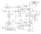
- FIG. 1is a schematic view of a system of one embodiment of the present invention.
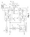
- FIG. 2is a control flow diagram of an overspeed control of the system shown in FIG. 1 .
- FIG. 1depicts system 20 of one embodiment of the present invention.
- System 20includes gas turbine engine 22 with selected components schematically represented in FIG. 1 . These components include compressor 24 , rotatable shaft 26 , turbine 28 , and combustor 29 .
- Shaft 26is mechanically coupled to compressor 24 and turbine 28 to collectively turn about rotational axis R—R.
- Combustor 29is positioned between compressor 24 and turbine 28 along axis R—R.
- Combustor 29selectively receives fuel from fuel subsystem 30 of system 20 .
- Gas turbine engine 22is configured with an intake (not shown) to deliver air to compressor 24 .
- Compressor 24pressurizes the air as it rotates with shaft 26 . At least a portion of this pressurized air is provided from compressor 24 to combustor 29 for mixing with fuel from fuel subsystem 30 . The resulting fuel/air mixture is ignited, producing hot, expanding exhaust gases that cause turbine 28 to rotate before being discharged through an outlet (not shown) of gas turbine engine 22 .
- shaft 26turns, causing compressor 24 to rotate; thereby continuing to supply pressurized air for sustained combustion.
- gas turbine engine 22may include a number of other components that are not shown to enhance clarity. Further, compressor 24 and/or turbine 28 may be of a single or multi-stage variety. Alternatively or additionally, gas turbine engine 22 may include multiple spools each comprised of a compressor rotatably coupled by a shaft to a turbine. In one common “dual spool” configuration, the shafts of two spools are arranged concentric to one another to correspondingly provide a low pressure or fan stage compressor upstream of a high pressure compressor, with a corresponding pair of turbines to drive the low and high pressure stages. In another configuration, gas turbine engine 22 also includes a turbine that is not coupled to a compressor and correspondingly is capable of rotating freely relative to any compressor. Instead, this free turbine is typically arranged to turn a shaft for delivering mechanical power.
- gas turbine engine load 32is shown coupled to gas turbine engine 22 by power shaft 34 .
- shaft 34is coupled to propulsion rotor 36 by a mechanical linkage 38 .
- load 32is representative of a helicopter or turboprop propulsion arrangement that is often powered by a gas turbine engine of the free turbine variety.
- gas turbine engine 22may be configured to provide thrust by the discharge of working fluid through a nozzle of engine 22 (not shown), which serves as the primary source of propulsion.
- System 20also includes overspeed control 40 .
- Overspeed control 40is coupled to gas turbine engine 22 by rotational speed sensor 42 of system 20 .
- Rotational speed sensor 42generates signal “n” representative of the speed of turbine 28 or another rotating member of gas turbine engine 22 .
- Fuel supply subsystem 30includes fuel source 44 that selectively delivers fuel through actuatable valve 46 to gas turbine engine 22 via conduit 48 in the direction indicated by arrow F.
- Valve 46is responsive to signals from overspeed control 40 to reduce or cut-off fuel flow to gas turbine engine 22 .
- fuel supply subsystem 30includes one or more fuel pumps, fuel meters, fuel regulators, and/or fuel modulators not shown to enhance clarity.
- Overspeed control 40includes analog circuit 50 .
- Analog circuit 50includes drivers 60 a , 60 b .
- Drivers 60 a , 60 beach include a corresponding comparator (COMP.) 62 a , 62 b .
- Drivers 60 a , 60 balso each include a switch (SW) 64 a, 64 b coupled to an output of comparator 62 a , 62 b , respectively.
- SWswitch
- Comparators 62 a , 62 bare each responsive to at least two inputs. Comparator 62 a compares the level of signal n from speed sensor 42 to a predetermined speed limit signal L 1 as provided by limit generator 70 .
- signal L 1is provided as a voltage level with generator 70 being in the form of a constant or adjustable voltage input. In another embodiment, signal L 1 may correspond to an analog current level with generator 70 configured accordingly. Typically, during operation of system 20 , the level of signal L 1 is generally maintained constant. However, it is envisioned that generator 70 may be configured to permit operator adjustments from time to time for calibration or other purposes.
- Comparator 62 bcompares the level of signal n to a different speed limit signal L 2 .
- Signal L 2is received by comparator 62 b from variable limit generator 72 .
- output signal C 2 of comparator 62 bchanges state to activate (close) switch 64 b .
- Generator 72provides L 2 from a predefined range of potential values. This range has a lower extreme L 2 LO and an upper extreme L 2 UP (range L 2 LO:L 2 UP).
- signal L 2 output from range L 2 LO:L 2 UPis based on rate of change of rotational speed (rotational acceleration), as determined from signal n. This rate of change of rotational speed is represented by signal n′.
- Differentiator 74provides signal n′ from signal n.
- Variable limit generator 72may be provided in any of a number of forms.
- generator 72is provided by a circuit that outputs signal L 2 as a linear voltage or current level between the extremes L 2 LO, L 2 UP, with L 2 being directly proportional to n′. For this embodiment, if either extreme is reached, then generator 72 maintains the output at the corresponding extreme until n′ changes to once again be within the variable range L 2 LO:L 2 UP.
- the variation of signal L 2 between extremes L 2 LO and L 2 UPmay not be linear with respect to input signal n′, instead, a different functional relationship including a discrete, polynomial, exponential, or logarithmic relationship may be additionally or alternatively used, just to name a few.
- comparators 62 a , 62 bmay be of the differential operational amplifier type and/or may be based on one or more arrangements of discrete components, transistor mirrors and the like. Also, comparators 62 a , 62 b may include a degree of hysteresis to reduce false triggering. Switches 62 a , 62 b may be in a form that includes a bipolar transistor and/or Field Effect Transistor (FET), an electromagnetic relay, solid state relay, optically activated switch, Silicon Controller Rectifier (SCR), triac, or such other type of switching device as would occur to those skilled in the art, including those of a mechanical, electromechanical, optical, solid-state, or other variety. While shown as discrete blocks, it is envisioned that differentiator 74 and/or generator 70 , 72 may be part of one or more networks of passive and/or active components arranged to provide the desired operation.
- FETField Effect Transistor
- SCRSilicon Controller Rectifier
- actuatable valve 46includes actuator 82 and mechanical valve 84 .
- Valve 84changes position in response to activation of actuator 82 .
- actuator 82is in the form of a solenoid that is activated by the flow of current through a corresponding electrical coil as schematically illustrated in FIG. 2 .
- FIG. 2it should be recognized that other forms of actuators and/or actuatable valve arrangements are also contemplated as would occur to those skilled in the art.
- Activation of actuator 82requires sourcing electrical current I to actuator 82 from electrical power source 86 through switch 64 a of driver 60 a . Electrical current I is sunk to ground G from actuator 82 through switch 64 b of driver 60 b .
- both switches 64 a , 64 bare “closed” corresponding to active states of signals C 1 , C 2 from comparators 62 a , 62 b .
- signal nexceeds both speed limit signals L 1 and L 2 .
- Circuit 50may be arranged to discriminate between speed/acceleration characteristic of an engine load loss and a tolerable overspeed excursion.
- generator 70sets signal L 1 to correspond to a static overspeed level, and generator 72 sets L 2 LO less than or equal to L 1 and L 2 UP greater than L 1 , such that: L 2 LO ⁇ L 1 ⁇ L 2 UP.
- Activation of valve 46depends on switches 64 a , 64 b being concurrently closed, corresponding to a level of signal n that exceeds signals L 1 and L 2 .
- L 2 > 1overspeed excursions between L 1 and L 2 can occur without closing both switches 64 a , 64 b .
- L 2 UPcorresponds to a steady-state overspeed trip point
- L 2 LOcorresponds to an unacceptable transient overspeed trip point.
- the dynamic range L 1 :L 2is greatest during steady-state operation and decreases to approximately zero with increasing acceleration.
- Engine overspeedcan be expressed in terms relative to a rated speed, such as a nominal maximum design speed. Typically, overspeed beyond the maximum design speed is acceptable for brief periods of time. As a result, overspeed trip points may be set greater than 100% of the maximum design speed. In one instance, L 1 and L 2 LO are set to 105% of the nominal maximum and L 2 UP is set to 125% of the nominal maximum. These values are believed to be particularly applicable to the Rolls Royce Allison Model No. 250-C40 gas turbine engine.
- relative levelsmay not be used and/or one or more overspeed trip points may not exceed 100% of the maximum speed rating.
- measurements of n and/or n′may be subject to high frequency noise that could result in a very high, momentary acceleration reading, causing an undesirable lowering of the level for signal L 2 .
- filteringit may be desirable to include filtering to selectively detect and reduce the high frequency components of signals n′ and/or n.
- overspeed control 40may be defined in part or in whole by one or more controllers for system 20 that are directed to other operations, as well.
- overspeed control 40may be part of circuitry designed to modulate fuel flow to gas turbine engine 22 in response to a throttle and/or other inputs.
- fuel modulationis accomplished with a different valve than overspeed control valve 46 ; however, the same valve may be used in some applications.
- other embodiments of system 20may partially or wholly define circuit 50 in terms of digital components, firmware, and/or software.
- generator 72may be provided in the form of a digital look-up table in the memory of a processor; differentiator 74 may be provided in the form of an approximating algorithm; and generator 70 may be provided as a digital value.
- comparators 62 a , 62 bmay be in a digital form suitable for interfacing with digital values for signals n, L 1 , and L 2 . In one particular application, one or more of these functions may be incorporated into a Full Authority Digital Engine Control (FADEC) for system 20 .
- FADECFull Authority Digital Engine Control
- redundant speed sensorsmay be utilized to assure overspeed detection in the event of the failure of one of the sensors, with overspeed control 40 correspondingly adjusted.
- two speed sensorsare used and the circuitry adapted, so that values of signals n and n′ from either sensor will cause actuation of valve 46 .
- sensors pertaining to the speed, and/or operation of load 32may be incorporated into overspeed control 40 to further refine the determination as to when an overspeed condition should be recognized and addressed.
Landscapes
- Engineering & Computer Science (AREA)
- Chemical & Material Sciences (AREA)
- Combustion & Propulsion (AREA)
- Mechanical Engineering (AREA)
- General Engineering & Computer Science (AREA)
- Physics & Mathematics (AREA)
- General Physics & Mathematics (AREA)
- Automation & Control Theory (AREA)
- Control Of Turbines (AREA)
Abstract
Description
Claims (21)
Priority Applications (1)
| Application Number | Priority Date | Filing Date | Title |
|---|---|---|---|
| US09/497,558US6321525B1 (en) | 2000-02-03 | 2000-02-03 | Overspeed detection techniques for gas turbine engine |
Applications Claiming Priority (1)
| Application Number | Priority Date | Filing Date | Title |
|---|---|---|---|
| US09/497,558US6321525B1 (en) | 2000-02-03 | 2000-02-03 | Overspeed detection techniques for gas turbine engine |
Publications (1)
| Publication Number | Publication Date |
|---|---|
| US6321525B1true US6321525B1 (en) | 2001-11-27 |
Family
ID=23977339
Family Applications (1)
| Application Number | Title | Priority Date | Filing Date |
|---|---|---|---|
| US09/497,558Expired - LifetimeUS6321525B1 (en) | 2000-02-03 | 2000-02-03 | Overspeed detection techniques for gas turbine engine |
Country Status (1)
| Country | Link |
|---|---|
| US (1) | US6321525B1 (en) |
Cited By (67)
| Publication number | Priority date | Publication date | Assignee | Title |
|---|---|---|---|---|
| US6392446B1 (en)* | 2001-06-01 | 2002-05-21 | Hewlett-Packard Company | Device and method for reducing a time constant of a data bus during a voltage transition |
| US20030137275A1 (en)* | 2001-12-26 | 2003-07-24 | Aisin Aw Co., Ltd. | Driving control device and method for electric vehicle and program therefor |
| WO2004005938A1 (en)* | 2002-07-04 | 2004-01-15 | Siemens Aktiengesellschaft | Device for determining the rotational speed of a rotating machine part using redundant sensors and evaluation circuits |
| EP1560338A1 (en)* | 2004-01-27 | 2005-08-03 | Siemens Aktiengesellschaft | Method for storing of process signals from a technical installation |
| US20050193739A1 (en)* | 2004-03-02 | 2005-09-08 | General Electric Company | Model-based control systems and methods for gas turbine engines |
| US20050200349A1 (en)* | 2004-03-15 | 2005-09-15 | Brant Duke | Method and apparatus of determining gas turbine shaft speed |
| US20070000230A1 (en)* | 2005-07-01 | 2007-01-04 | Ics Triplex Technology Ltd. | Turbo machinery speed monitor |
| US20070113559A1 (en)* | 2004-06-03 | 2007-05-24 | Raymond Zagranski | Overspeed limiter for turboshaft engines |
| WO2007098004A3 (en)* | 2006-02-16 | 2007-12-06 | Frost Links Inc | Conveyor chain pin with reservoir |
| EP1870565A1 (en)* | 2006-06-23 | 2007-12-26 | Siemens Aktiengesellschaft | Prevention of unacceptably high turbo groups speeds |
| RU2316665C1 (en)* | 2006-04-27 | 2008-02-10 | Открытое акционерное общество "Авиадвигатель" | Method to protect gas-turbine plant from overspeeding of power turbine |
| FR2921974A1 (en)* | 2007-10-08 | 2009-04-10 | Hispano Suiza Sa | Shaft rupture detecting device for twin-casing gas turbine engine of aircraft, has processing unit providing anomaly signal when characteristic has value that exceeds preset speed threshold, and variation rate that exceeds preset rate limit |
| RU2374473C1 (en)* | 2008-05-07 | 2009-11-27 | Закрытое акционерное общество научно-производственная фирма ЗАО НПФ "ГАЗ-система-сервис" | Method to control gas turbine engine with free turbine |
| RU2375598C1 (en)* | 2008-04-30 | 2009-12-10 | Закрытое акционерное общество научно-производственная фирма ЗАО НПФ "ГАЗ-система-сервис" | Method to control gas tyrbine engine with free turbine |
| GB2461609A (en)* | 2008-07-10 | 2010-01-13 | Gen Electric | Method and system to facilitate over-speed protection |
| US20100005657A1 (en)* | 2008-07-10 | 2010-01-14 | Van Vactor David R | Methods and systems to facilitate over-speed protection |
| US20100010721A1 (en)* | 2008-07-10 | 2010-01-14 | Van Vactor David R | Methods and systems to facilitate over-speed protection |
| US20100010720A1 (en)* | 2008-07-10 | 2010-01-14 | Van Vactor David R | Methods and systems to facilitate over-speed protection |
| RU2380561C1 (en)* | 2008-06-05 | 2010-01-27 | Закрытое акционерное общество научно-производственная фирма ЗАО НПФ "ГАЗ-система-сервис" | Methods of control of gas-turbine electric power plant |
| RU2383755C1 (en)* | 2008-08-04 | 2010-03-10 | Закрытое акционерное общество научно-производственная фирма ЗАО НПФ "ГАЗ-система-сервис" | Method to control gas turbine engine |
| US20100168952A1 (en)* | 2008-12-30 | 2010-07-01 | Ronald Alan Falkmann | Gas turbine engine failure detection |
| RU2408790C2 (en)* | 2009-02-03 | 2011-01-10 | Закрытое акционерное общество научно-производственная фирма ЗАО НПФ "ГАЗ-система-сервис" | Control method of gas turbine electric power station |
| RU2416730C1 (en)* | 2009-10-26 | 2011-04-20 | Закрытое акционерное общество научно-производственная фирма ЗАО НПФ "ГАЗ-система-сервис" | Method of control over gas turbine electric power station |
| RU2418182C2 (en)* | 2008-08-04 | 2011-05-10 | Открытое акционерное общество "СТАР" | Method of control over gas turbine engine |
| RU2422657C1 (en)* | 2009-12-23 | 2011-06-27 | Закрытое акционерное общество научно-производственная фирма ЗАО НПФ "ГАЗ-система-сервис" | Gas turbine electric power station control method |
| RU2425997C1 (en)* | 2009-12-30 | 2011-08-10 | Закрытое Акционерное Общество Научно-Производственная Фирма "Газ-Система-Сервис" | Method of control over gas turbine electric power station |
| RU2425996C1 (en)* | 2009-12-28 | 2011-08-10 | Закрытое Акционерное Общество Научно-Производственная Фирма "Газ-Система-Сервис" | Method of control over gas turbine unit |
| RU2427722C1 (en)* | 2009-12-22 | 2011-08-27 | Закрытое акционерное общество научно-производственная фирма ЗАО НПФ "ГАЗ-система-сервис" | Gas turbine plant control method |
| RU2431051C1 (en)* | 2010-01-11 | 2011-10-10 | Закрытое акционерное общество научно-производственная фирма ЗАО НПФ "ГАЗ-система-сервис" | Gas turbine plant control method |
| RU2431753C1 (en)* | 2010-03-15 | 2011-10-20 | Закрытое Акционерное Общество Научно-Производственная Фирма "Газ-Система-Сервис" | Gas turbine plant control method |
| RU2435970C1 (en)* | 2010-03-31 | 2011-12-10 | Закрытое акционерное общество научно-производственная фирма ЗАО НПФ "ГАЗ-система-сервис" | Gas turbine plant control method |
| RU2436978C2 (en)* | 2010-01-11 | 2011-12-20 | Открытое акционерное общество "СТАР" | Gas turbine engine control method |
| GB2488805A (en)* | 2011-03-09 | 2012-09-12 | Rolls Royce Plc | Shaft break detection |
| RU2464438C1 (en)* | 2011-04-29 | 2012-10-20 | Открытое акционерное общество "Авиадвигатель" | Control method of active power of electric power plant |
| US20130138322A1 (en)* | 2011-11-08 | 2013-05-30 | Thales | Full authority digital engine control system for aircraft engine |
| RU2489592C1 (en)* | 2011-12-30 | 2013-08-10 | Открытое акционерное общество "СТАР" | Method of controlling fuel feed to gas turbine engine |
| FR2987085A1 (en)* | 2012-02-20 | 2013-08-23 | Snecma | METHOD FOR SECURING THE OPERATION OF A TURBOMACHINE |
| RU2493393C2 (en)* | 2011-11-01 | 2013-09-20 | Открытое акционерное общество "СТАР" | Method of protection of shipboard gas turbine plant |
| RU2493392C2 (en)* | 2011-10-21 | 2013-09-20 | Открытое акционерное общество "СТАР" | Method of gas turbine engine |
| RU2497001C1 (en)* | 2012-05-10 | 2013-10-27 | Открытое акционерное общество "СТАР" | Method of controlling fuel feed to gas turbine engine |
| US20140095051A1 (en)* | 2012-09-28 | 2014-04-03 | Pratt & Whitney Canada Corp. | Adaptive fuel manifold filling function for improved engine start |
| RU2514463C1 (en)* | 2012-09-07 | 2014-04-27 | Закрытое Акционерное Общество Научно-Производственная Фирма "Газ-Система-Сервис" | Control over gas turbine engine compressor actuators |
| RU2534199C1 (en)* | 2013-12-19 | 2014-11-27 | Открытое акционерное общество "Омское машиностроительное конструкторское бюро" | Fuel system for pairs of helicopter turbine jets |
| US20150105997A1 (en)* | 2013-10-10 | 2015-04-16 | Robert Bosch Gmbh | Method and device for monitoring a drive of a motor vehicle |
| FR3013390A1 (en)* | 2013-11-19 | 2015-05-22 | Turbomeca | TURBOMACHINE AND REGULATION METHOD |
| US9052330B2 (en) | 2010-08-16 | 2015-06-09 | Invensys Systems, Inc. | Enhanced rotation measurement |
| EP2881549A1 (en)* | 2013-12-05 | 2015-06-10 | General Electric Company | System and method for preventing an emergency over-speed condition in a rotating machine |
| WO2015047468A3 (en)* | 2013-06-24 | 2015-06-18 | United Technologies Corporation | Over speed monitoring using a fan drive gear system |
| FR3023872A1 (en)* | 2014-07-21 | 2016-01-22 | Sagem Defense Securite | DEVICE FOR PROTECTION AGAINST OVERSPEED OF AN AIRCRAFT ENGINE |
| US9291107B2 (en) | 2013-03-15 | 2016-03-22 | Paccar Inc | Engine overspeed shutdown systems and methods |
| US20160158815A1 (en)* | 2008-02-01 | 2016-06-09 | Woodward, Inc. | Digital closed loop proportional hydraulic pressure controller |
| US20160265445A1 (en)* | 2015-03-11 | 2016-09-15 | Pratt & Whitney Canada Corp. | Overthrust protection system and method |
| RU2638497C1 (en)* | 2017-03-09 | 2017-12-13 | АО "НПП "Темп" им.Ф.Короткова" | Method of gas-turbine engine control |
| RU2639923C1 (en)* | 2017-01-27 | 2017-12-25 | Виктор Васильевич Попов | Method of mechanization control of gas turbine engine compressor |
| US9869249B2 (en) | 2012-01-31 | 2018-01-16 | United Technologies Corporation | Speed sensor probe location in gas turbine engine |
| US9932906B2 (en) | 2015-09-23 | 2018-04-03 | Honeywell International Inc. | Gas turbine engine uncontrolled high thrust detection system and method |
| RU2658709C2 (en)* | 2016-11-15 | 2018-06-22 | Виктор Васильевич Попов | Gas turbine engine compressor mechanization control device |
| US10112723B2 (en)* | 2015-03-31 | 2018-10-30 | Airbus Helicopters | Method and a device for stopping a turboshaft engine in nominal operation |
| US10150569B2 (en)* | 2014-09-26 | 2018-12-11 | Airbus Helicopters | Method of stopping a rotorcraft engine in overspeed, and a system and a rotorcraft associated therewith |
| CN109356727A (en)* | 2017-07-28 | 2019-02-19 | 通用电气阿维奥有限责任公司 | System for controlling the output of a gas generator and method of controlling its power and torque output |
| CN109632328A (en)* | 2019-01-21 | 2019-04-16 | 中国航发湖南动力机械研究所 | Turboshaft engine checkout facility device, system and method |
| US20190226399A1 (en)* | 2009-12-11 | 2019-07-25 | Airbus Helicopters | Method of increasing the safety of a power plant, and a power plant suitable for implementing the method |
| US10801361B2 (en) | 2016-09-09 | 2020-10-13 | General Electric Company | System and method for HPT disk over speed prevention |
| EP3904660A1 (en)* | 2020-04-29 | 2021-11-03 | Pratt & Whitney Canada Corp. | System and method for detecting a shaft event on a gas turbine engine |
| CN113803170A (en)* | 2020-06-17 | 2021-12-17 | 空客直升机 | Method for stopping an overspeed engine, associated system and rotorcraft |
| RU2776229C1 (en)* | 2022-02-04 | 2022-07-14 | Общество с ограниченной ответственностью внедренческая фирма "ЭЛНА" | Autonomous gas turbine engine protection unit and its operation method |
| US11629649B2 (en) | 2020-05-11 | 2023-04-18 | Raytheon Technologies Corporation | Gas turbine engine with speed sensor |
Citations (24)
| Publication number | Priority date | Publication date | Assignee | Title |
|---|---|---|---|---|
| US3928962A (en)* | 1973-04-27 | 1975-12-30 | Lucas Aerospace Ltd | Fuel control systems for gas turbine engines |
| US3932058A (en) | 1974-06-07 | 1976-01-13 | United Technologies Corporation | Control system for variable pitch fan propulsor |
| US3939649A (en) | 1971-02-01 | 1976-02-24 | Chandler Evans Inc. | Fuel control |
| US3956884A (en) | 1974-07-09 | 1976-05-18 | Lucas Industries Limited | Gas turbine engine fuel control systems |
| US4045955A (en)* | 1975-08-29 | 1977-09-06 | Stal-Laval Turbin Ab | Regulating means for gas turbine plant |
| US4218879A (en) | 1978-10-30 | 1980-08-26 | Mcdonnell Douglas Corporation | Overspeed protection device |
| US4248040A (en) | 1979-06-04 | 1981-02-03 | General Electric Company | Integrated control system for a gas turbine engine |
| US4302931A (en) | 1980-06-16 | 1981-12-01 | Cnandler Evans Inc. | Fuel flow limiting device for overspeed and overtemperature control |
| US4423593A (en) | 1982-04-16 | 1984-01-03 | Chandler Evans Inc. | Fuel control for controlling helicopter rotor/turbine acceleration |
| US4474013A (en) | 1983-11-23 | 1984-10-02 | General Electric Company | Overspeed anticipation circuit for steam turbine speed control |
| US4478038A (en) | 1982-09-20 | 1984-10-23 | Chandler Evans, Inc. | Electronic fuel control with manual training mode |
| US4528812A (en) | 1982-07-27 | 1985-07-16 | Rolls-Royce Limited | Fuel control system for a gas turbine engine |
| US4578945A (en) | 1983-11-10 | 1986-04-01 | Chandler Evans Inc. | Overspeed limiter for gas turbine fuel control |
| US4593523A (en) | 1980-12-17 | 1986-06-10 | Allied Corporation | Method and apparatus for acceleration limiting a gas turbine engine |
| US4845943A (en) | 1988-04-29 | 1989-07-11 | United Technologies Corporation | Control method for topping loop |
| US4987737A (en) | 1986-11-26 | 1991-01-29 | Rolls-Royce Plc | Fuel control system for gas turbine aeroengine overspeed protection |
| US4998949A (en) | 1987-12-24 | 1991-03-12 | Rolls-Royce Plc | Overspeed limiter for gas turbine aeroengine |
| US5134845A (en) | 1990-07-23 | 1992-08-04 | United Technologies Corporation | Control for a gas turbine engine |
| US5301499A (en) | 1990-06-28 | 1994-04-12 | General Electric Company | Overspeed anticipation and control system for single shaft combined cycle gas and steam turbine unit |
| US5440490A (en) | 1992-11-20 | 1995-08-08 | Rolls-Royce Plc | Aircraft engine emergency control system |
| US5486997A (en) | 1994-08-04 | 1996-01-23 | General Electric Company | Predictor algorithm for actuator control |
| US5579632A (en) | 1995-04-10 | 1996-12-03 | Alliedsignal Inc. | Overspeed governor control system |
| US5927064A (en) | 1997-12-23 | 1999-07-27 | United Technologies Corporation | Start, shutoff and overspeed system for gas turbine engine |
| US5953902A (en)* | 1995-08-03 | 1999-09-21 | Siemens Aktiengesellschaft | Control system for controlling the rotational speed of a turbine, and method for controlling the rotational speed of a turbine during load shedding |
- 2000
- 2000-02-03USUS09/497,558patent/US6321525B1/ennot_activeExpired - Lifetime
Patent Citations (24)
| Publication number | Priority date | Publication date | Assignee | Title |
|---|---|---|---|---|
| US3939649A (en) | 1971-02-01 | 1976-02-24 | Chandler Evans Inc. | Fuel control |
| US3928962A (en)* | 1973-04-27 | 1975-12-30 | Lucas Aerospace Ltd | Fuel control systems for gas turbine engines |
| US3932058A (en) | 1974-06-07 | 1976-01-13 | United Technologies Corporation | Control system for variable pitch fan propulsor |
| US3956884A (en) | 1974-07-09 | 1976-05-18 | Lucas Industries Limited | Gas turbine engine fuel control systems |
| US4045955A (en)* | 1975-08-29 | 1977-09-06 | Stal-Laval Turbin Ab | Regulating means for gas turbine plant |
| US4218879A (en) | 1978-10-30 | 1980-08-26 | Mcdonnell Douglas Corporation | Overspeed protection device |
| US4248040A (en) | 1979-06-04 | 1981-02-03 | General Electric Company | Integrated control system for a gas turbine engine |
| US4302931A (en) | 1980-06-16 | 1981-12-01 | Cnandler Evans Inc. | Fuel flow limiting device for overspeed and overtemperature control |
| US4593523A (en) | 1980-12-17 | 1986-06-10 | Allied Corporation | Method and apparatus for acceleration limiting a gas turbine engine |
| US4423593A (en) | 1982-04-16 | 1984-01-03 | Chandler Evans Inc. | Fuel control for controlling helicopter rotor/turbine acceleration |
| US4528812A (en) | 1982-07-27 | 1985-07-16 | Rolls-Royce Limited | Fuel control system for a gas turbine engine |
| US4478038A (en) | 1982-09-20 | 1984-10-23 | Chandler Evans, Inc. | Electronic fuel control with manual training mode |
| US4578945A (en) | 1983-11-10 | 1986-04-01 | Chandler Evans Inc. | Overspeed limiter for gas turbine fuel control |
| US4474013A (en) | 1983-11-23 | 1984-10-02 | General Electric Company | Overspeed anticipation circuit for steam turbine speed control |
| US4987737A (en) | 1986-11-26 | 1991-01-29 | Rolls-Royce Plc | Fuel control system for gas turbine aeroengine overspeed protection |
| US4998949A (en) | 1987-12-24 | 1991-03-12 | Rolls-Royce Plc | Overspeed limiter for gas turbine aeroengine |
| US4845943A (en) | 1988-04-29 | 1989-07-11 | United Technologies Corporation | Control method for topping loop |
| US5301499A (en) | 1990-06-28 | 1994-04-12 | General Electric Company | Overspeed anticipation and control system for single shaft combined cycle gas and steam turbine unit |
| US5134845A (en) | 1990-07-23 | 1992-08-04 | United Technologies Corporation | Control for a gas turbine engine |
| US5440490A (en) | 1992-11-20 | 1995-08-08 | Rolls-Royce Plc | Aircraft engine emergency control system |
| US5486997A (en) | 1994-08-04 | 1996-01-23 | General Electric Company | Predictor algorithm for actuator control |
| US5579632A (en) | 1995-04-10 | 1996-12-03 | Alliedsignal Inc. | Overspeed governor control system |
| US5953902A (en)* | 1995-08-03 | 1999-09-21 | Siemens Aktiengesellschaft | Control system for controlling the rotational speed of a turbine, and method for controlling the rotational speed of a turbine during load shedding |
| US5927064A (en) | 1997-12-23 | 1999-07-27 | United Technologies Corporation | Start, shutoff and overspeed system for gas turbine engine |
Cited By (112)
| Publication number | Priority date | Publication date | Assignee | Title |
|---|---|---|---|---|
| US6392446B1 (en)* | 2001-06-01 | 2002-05-21 | Hewlett-Packard Company | Device and method for reducing a time constant of a data bus during a voltage transition |
| US7227332B2 (en)* | 2001-12-26 | 2007-06-05 | Aisin Aw Co., Ltd. | Driving control device and method for electric vehicle and program therefor |
| US20030137275A1 (en)* | 2001-12-26 | 2003-07-24 | Aisin Aw Co., Ltd. | Driving control device and method for electric vehicle and program therefor |
| WO2004005938A1 (en)* | 2002-07-04 | 2004-01-15 | Siemens Aktiengesellschaft | Device for determining the rotational speed of a rotating machine part using redundant sensors and evaluation circuits |
| EP1560338A1 (en)* | 2004-01-27 | 2005-08-03 | Siemens Aktiengesellschaft | Method for storing of process signals from a technical installation |
| WO2005071847A1 (en)* | 2004-01-27 | 2005-08-04 | Siemens Aktiengesellschaft | Method for storing process signals of a technical installation |
| US7941262B2 (en) | 2004-01-27 | 2011-05-10 | Siemens Aktiengesellschaft | Method for storing plant process signals |
| US20070162213A1 (en)* | 2004-01-27 | 2007-07-12 | Andreas Bode | Method for storing plant process signals |
| US20050193739A1 (en)* | 2004-03-02 | 2005-09-08 | General Electric Company | Model-based control systems and methods for gas turbine engines |
| US20050200349A1 (en)* | 2004-03-15 | 2005-09-15 | Brant Duke | Method and apparatus of determining gas turbine shaft speed |
| US20070113559A1 (en)* | 2004-06-03 | 2007-05-24 | Raymond Zagranski | Overspeed limiter for turboshaft engines |
| US20070000230A1 (en)* | 2005-07-01 | 2007-01-04 | Ics Triplex Technology Ltd. | Turbo machinery speed monitor |
| EP1739437A3 (en)* | 2005-07-01 | 2008-07-09 | ICS Triplex Technology Limited | Turbo machinery speed monitor |
| US7509189B2 (en) | 2005-07-01 | 2009-03-24 | Ics Triplex Technology Limited | Turbo machinery speed monitor |
| WO2007098004A3 (en)* | 2006-02-16 | 2007-12-06 | Frost Links Inc | Conveyor chain pin with reservoir |
| RU2316665C1 (en)* | 2006-04-27 | 2008-02-10 | Открытое акционерное общество "Авиадвигатель" | Method to protect gas-turbine plant from overspeeding of power turbine |
| EP1870565A1 (en)* | 2006-06-23 | 2007-12-26 | Siemens Aktiengesellschaft | Prevention of unacceptably high turbo groups speeds |
| FR2921974A1 (en)* | 2007-10-08 | 2009-04-10 | Hispano Suiza Sa | Shaft rupture detecting device for twin-casing gas turbine engine of aircraft, has processing unit providing anomaly signal when characteristic has value that exceeds preset speed threshold, and variation rate that exceeds preset rate limit |
| US20160158815A1 (en)* | 2008-02-01 | 2016-06-09 | Woodward, Inc. | Digital closed loop proportional hydraulic pressure controller |
| US10175703B2 (en)* | 2008-02-01 | 2019-01-08 | Woodward, Inc. | Digital closed loop proportional hydraulic pressure controller |
| RU2375598C1 (en)* | 2008-04-30 | 2009-12-10 | Закрытое акционерное общество научно-производственная фирма ЗАО НПФ "ГАЗ-система-сервис" | Method to control gas tyrbine engine with free turbine |
| RU2374473C1 (en)* | 2008-05-07 | 2009-11-27 | Закрытое акционерное общество научно-производственная фирма ЗАО НПФ "ГАЗ-система-сервис" | Method to control gas turbine engine with free turbine |
| RU2380561C1 (en)* | 2008-06-05 | 2010-01-27 | Закрытое акционерное общество научно-производственная фирма ЗАО НПФ "ГАЗ-система-сервис" | Methods of control of gas-turbine electric power plant |
| US8224552B2 (en) | 2008-07-10 | 2012-07-17 | General Electric Company | Methods and systems to facilitate over-speed protection |
| GB2461609A (en)* | 2008-07-10 | 2010-01-13 | Gen Electric | Method and system to facilitate over-speed protection |
| GB2461609B (en)* | 2008-07-10 | 2012-01-25 | Gen Electric | Methods and systems to facilitate over-speed protection |
| US20100010721A1 (en)* | 2008-07-10 | 2010-01-14 | Van Vactor David R | Methods and systems to facilitate over-speed protection |
| US20100005657A1 (en)* | 2008-07-10 | 2010-01-14 | Van Vactor David R | Methods and systems to facilitate over-speed protection |
| US8321119B2 (en)* | 2008-07-10 | 2012-11-27 | General Electric Company | Methods and systems to facilitate over-speed protection |
| US20100010720A1 (en)* | 2008-07-10 | 2010-01-14 | Van Vactor David R | Methods and systems to facilitate over-speed protection |
| RU2418182C2 (en)* | 2008-08-04 | 2011-05-10 | Открытое акционерное общество "СТАР" | Method of control over gas turbine engine |
| RU2383755C1 (en)* | 2008-08-04 | 2010-03-10 | Закрытое акционерное общество научно-производственная фирма ЗАО НПФ "ГАЗ-система-сервис" | Method to control gas turbine engine |
| US20100168952A1 (en)* | 2008-12-30 | 2010-07-01 | Ronald Alan Falkmann | Gas turbine engine failure detection |
| US8954228B2 (en) | 2008-12-30 | 2015-02-10 | Rolls-Royce Corporation | Gas turbine engine failure detection |
| RU2408790C2 (en)* | 2009-02-03 | 2011-01-10 | Закрытое акционерное общество научно-производственная фирма ЗАО НПФ "ГАЗ-система-сервис" | Control method of gas turbine electric power station |
| RU2416730C1 (en)* | 2009-10-26 | 2011-04-20 | Закрытое акционерное общество научно-производственная фирма ЗАО НПФ "ГАЗ-система-сервис" | Method of control over gas turbine electric power station |
| US20190226399A1 (en)* | 2009-12-11 | 2019-07-25 | Airbus Helicopters | Method of increasing the safety of a power plant, and a power plant suitable for implementing the method |
| US10890112B2 (en)* | 2009-12-11 | 2021-01-12 | Airbus Helicopters | Method of increasing the safety of a power plant, and a power plant suitable for implementing the method |
| RU2427722C1 (en)* | 2009-12-22 | 2011-08-27 | Закрытое акционерное общество научно-производственная фирма ЗАО НПФ "ГАЗ-система-сервис" | Gas turbine plant control method |
| RU2422657C1 (en)* | 2009-12-23 | 2011-06-27 | Закрытое акционерное общество научно-производственная фирма ЗАО НПФ "ГАЗ-система-сервис" | Gas turbine electric power station control method |
| RU2425996C1 (en)* | 2009-12-28 | 2011-08-10 | Закрытое Акционерное Общество Научно-Производственная Фирма "Газ-Система-Сервис" | Method of control over gas turbine unit |
| RU2425997C1 (en)* | 2009-12-30 | 2011-08-10 | Закрытое Акционерное Общество Научно-Производственная Фирма "Газ-Система-Сервис" | Method of control over gas turbine electric power station |
| RU2431051C1 (en)* | 2010-01-11 | 2011-10-10 | Закрытое акционерное общество научно-производственная фирма ЗАО НПФ "ГАЗ-система-сервис" | Gas turbine plant control method |
| RU2436978C2 (en)* | 2010-01-11 | 2011-12-20 | Открытое акционерное общество "СТАР" | Gas turbine engine control method |
| RU2431753C1 (en)* | 2010-03-15 | 2011-10-20 | Закрытое Акционерное Общество Научно-Производственная Фирма "Газ-Система-Сервис" | Gas turbine plant control method |
| RU2435970C1 (en)* | 2010-03-31 | 2011-12-10 | Закрытое акционерное общество научно-производственная фирма ЗАО НПФ "ГАЗ-система-сервис" | Gas turbine plant control method |
| US9383380B2 (en) | 2010-08-16 | 2016-07-05 | Invensys Systems, Inc. | Enhanced rotation measurement |
| US9052330B2 (en) | 2010-08-16 | 2015-06-09 | Invensys Systems, Inc. | Enhanced rotation measurement |
| EP2684020B1 (en)* | 2011-03-09 | 2019-04-24 | Rolls-Royce plc | Shaft break detection |
| US9506401B2 (en) | 2011-03-09 | 2016-11-29 | Rolls-Royce Plc | Method of detecting shaft break |
| GB2488805A (en)* | 2011-03-09 | 2012-09-12 | Rolls Royce Plc | Shaft break detection |
| US8943876B2 (en) | 2011-03-09 | 2015-02-03 | Rolls-Royce Plc | Shaft break detection |
| RU2464438C1 (en)* | 2011-04-29 | 2012-10-20 | Открытое акционерное общество "Авиадвигатель" | Control method of active power of electric power plant |
| RU2493392C2 (en)* | 2011-10-21 | 2013-09-20 | Открытое акционерное общество "СТАР" | Method of gas turbine engine |
| RU2493393C2 (en)* | 2011-11-01 | 2013-09-20 | Открытое акционерное общество "СТАР" | Method of protection of shipboard gas turbine plant |
| US9002616B2 (en)* | 2011-11-08 | 2015-04-07 | Thales | Full authority digital engine control system for aircraft engine |
| US20130138322A1 (en)* | 2011-11-08 | 2013-05-30 | Thales | Full authority digital engine control system for aircraft engine |
| RU2489592C1 (en)* | 2011-12-30 | 2013-08-10 | Открытое акционерное общество "СТАР" | Method of controlling fuel feed to gas turbine engine |
| US9869249B2 (en) | 2012-01-31 | 2018-01-16 | United Technologies Corporation | Speed sensor probe location in gas turbine engine |
| WO2013124578A1 (en)* | 2012-02-20 | 2013-08-29 | Snecma | Method for securing the operation of a turbomachine |
| US20150030464A1 (en)* | 2012-02-20 | 2015-01-29 | Snecma | Method for securing the operation of a turbomachine |
| FR2987085A1 (en)* | 2012-02-20 | 2013-08-23 | Snecma | METHOD FOR SECURING THE OPERATION OF A TURBOMACHINE |
| US10323538B2 (en)* | 2012-02-20 | 2019-06-18 | Safran Aircraft Engines | Method for securing the operation of a turbomachine |
| RU2497001C1 (en)* | 2012-05-10 | 2013-10-27 | Открытое акционерное общество "СТАР" | Method of controlling fuel feed to gas turbine engine |
| RU2514463C1 (en)* | 2012-09-07 | 2014-04-27 | Закрытое Акционерное Общество Научно-Производственная Фирма "Газ-Система-Сервис" | Control over gas turbine engine compressor actuators |
| US20140095051A1 (en)* | 2012-09-28 | 2014-04-03 | Pratt & Whitney Canada Corp. | Adaptive fuel manifold filling function for improved engine start |
| US9541005B2 (en)* | 2012-09-28 | 2017-01-10 | Pratt & Whitney Canada Corp. | Adaptive fuel manifold filling function for improved engine start |
| US9291107B2 (en) | 2013-03-15 | 2016-03-22 | Paccar Inc | Engine overspeed shutdown systems and methods |
| WO2015047468A3 (en)* | 2013-06-24 | 2015-06-18 | United Technologies Corporation | Over speed monitoring using a fan drive gear system |
| US20150105997A1 (en)* | 2013-10-10 | 2015-04-16 | Robert Bosch Gmbh | Method and device for monitoring a drive of a motor vehicle |
| JP2016538467A (en)* | 2013-11-19 | 2016-12-08 | ターボメカTurbomeca | Turbine engine and control method |
| KR20160085897A (en) | 2013-11-19 | 2016-07-18 | 터보메카 | Turbine engine and control method |
| US10190438B2 (en) | 2013-11-19 | 2019-01-29 | Safran Helicopter Engines | Turbine engine and control method |
| CN105745399A (en)* | 2013-11-19 | 2016-07-06 | 涡轮梅坎公司 | Turbine engine and control method |
| FR3013390A1 (en)* | 2013-11-19 | 2015-05-22 | Turbomeca | TURBOMACHINE AND REGULATION METHOD |
| WO2015075346A1 (en)* | 2013-11-19 | 2015-05-28 | Turbomeca | Turbine engine and control method |
| RU2670476C1 (en)* | 2013-11-19 | 2018-10-23 | Турбомека | Turbine engine and method for control thereof |
| CN105745399B (en)* | 2013-11-19 | 2018-05-11 | 涡轮梅坎公司 | Turbine engine and control method |
| EP2881549A1 (en)* | 2013-12-05 | 2015-06-10 | General Electric Company | System and method for preventing an emergency over-speed condition in a rotating machine |
| US10233771B2 (en) | 2013-12-05 | 2019-03-19 | General Electric Company | System and method for preventing an emergency over-speed condition in a rotating machine |
| RU2534199C1 (en)* | 2013-12-19 | 2014-11-27 | Открытое акционерное общество "Омское машиностроительное конструкторское бюро" | Fuel system for pairs of helicopter turbine jets |
| FR3023872A1 (en)* | 2014-07-21 | 2016-01-22 | Sagem Defense Securite | DEVICE FOR PROTECTION AGAINST OVERSPEED OF AN AIRCRAFT ENGINE |
| WO2016012713A1 (en)* | 2014-07-21 | 2016-01-28 | Sagem Defense Securite | Overspeed protection device of an aircraft engine |
| JP2017526861A (en)* | 2014-07-21 | 2017-09-14 | サフラン・エレクトロニクス・アンド・デファンス | Aircraft engine overspeed protection device |
| RU2680904C2 (en)* | 2014-07-21 | 2019-02-28 | Сафран Электроникс Энд Дифенс | Overspeed protection device of an aircraft engine |
| US20170211413A1 (en)* | 2014-07-21 | 2017-07-27 | Safran Electronics & Defense | Overspeed protection device of an aircraft engine |
| CN106536869A (en)* | 2014-07-21 | 2017-03-22 | 赛峰电子与防务公司 | Overspeed protection device of an aircraft engine |
| US10208620B2 (en)* | 2014-07-21 | 2019-02-19 | Safran Electronics & Defense | Overspeed protection device of an aircraft engine |
| US10150569B2 (en)* | 2014-09-26 | 2018-12-11 | Airbus Helicopters | Method of stopping a rotorcraft engine in overspeed, and a system and a rotorcraft associated therewith |
| US10487752B2 (en)* | 2015-03-11 | 2019-11-26 | Pratt & Whitney Canada Corp. | Overthrust protection system and method |
| US20160265445A1 (en)* | 2015-03-11 | 2016-09-15 | Pratt & Whitney Canada Corp. | Overthrust protection system and method |
| US10112723B2 (en)* | 2015-03-31 | 2018-10-30 | Airbus Helicopters | Method and a device for stopping a turboshaft engine in nominal operation |
| US9932906B2 (en) | 2015-09-23 | 2018-04-03 | Honeywell International Inc. | Gas turbine engine uncontrolled high thrust detection system and method |
| US10801361B2 (en) | 2016-09-09 | 2020-10-13 | General Electric Company | System and method for HPT disk over speed prevention |
| RU2658709C2 (en)* | 2016-11-15 | 2018-06-22 | Виктор Васильевич Попов | Gas turbine engine compressor mechanization control device |
| RU2639923C1 (en)* | 2017-01-27 | 2017-12-25 | Виктор Васильевич Попов | Method of mechanization control of gas turbine engine compressor |
| RU2638497C1 (en)* | 2017-03-09 | 2017-12-13 | АО "НПП "Темп" им.Ф.Короткова" | Method of gas-turbine engine control |
| CN109356727B (en)* | 2017-07-28 | 2021-09-21 | 通用电气阿维奥有限责任公司 | System for controlling output of gas generator and method for controlling power and torque output of gas generator |
| US11162433B2 (en)* | 2017-07-28 | 2021-11-02 | Ge Avio S.R.L. | Method of controlling gas generator power and torque output |
| CN109356727A (en)* | 2017-07-28 | 2019-02-19 | 通用电气阿维奥有限责任公司 | System for controlling the output of a gas generator and method of controlling its power and torque output |
| CN109632328B (en)* | 2019-01-21 | 2021-05-18 | 中国航发湖南动力机械研究所 | Turboshaft engine inspection test device, system and method |
| CN109632328A (en)* | 2019-01-21 | 2019-04-16 | 中国航发湖南动力机械研究所 | Turboshaft engine checkout facility device, system and method |
| EP3904660A1 (en)* | 2020-04-29 | 2021-11-03 | Pratt & Whitney Canada Corp. | System and method for detecting a shaft event on a gas turbine engine |
| US11499446B2 (en) | 2020-04-29 | 2022-11-15 | Pratt & Whitney Canada Corp. | System and method for detecting a shaft event on an engine |
| US11629649B2 (en) | 2020-05-11 | 2023-04-18 | Raytheon Technologies Corporation | Gas turbine engine with speed sensor |
| CN113803170A (en)* | 2020-06-17 | 2021-12-17 | 空客直升机 | Method for stopping an overspeed engine, associated system and rotorcraft |
| EP3926146A1 (en) | 2020-06-17 | 2021-12-22 | Airbus Helicopters | Method for stopping an engine in overspeed, associated system and rotorcraft |
| KR20210156206A (en)* | 2020-06-17 | 2021-12-24 | 에어버스 헬리콥터스 | Method for stopping an engine in overspeed, and associated system and rotorcraft |
| FR3111668A1 (en)* | 2020-06-17 | 2021-12-24 | Airbus Helicopters | Method for stopping an overspeed engine, associated system and rotorcraft |
| US11485485B2 (en) | 2020-06-17 | 2022-11-01 | Airbus Helicopters | Method for stopping an engine in overspeed, and associated system and rotorcraft |
| CN113803170B (en)* | 2020-06-17 | 2023-12-05 | 空客直升机 | Method for stopping an overspeed engine, associated system and rotorcraft |
| RU2776229C1 (en)* | 2022-02-04 | 2022-07-14 | Общество с ограниченной ответственностью внедренческая фирма "ЭЛНА" | Autonomous gas turbine engine protection unit and its operation method |
Similar Documents
| Publication | Publication Date | Title |
|---|---|---|
| US6321525B1 (en) | Overspeed detection techniques for gas turbine engine | |
| US5622045A (en) | System for detecting and accommodating gas turbine engine fan damage | |
| US4370560A (en) | Compressor load control for an auxiliary power unit | |
| US7818970B2 (en) | Controlling a gas turbine engine with a transient load | |
| US5233512A (en) | Method and apparatus for actuator fault detection | |
| US6718767B1 (en) | Variable geometry turbocharger control system | |
| US9982607B2 (en) | Shaft failure detection using passive control methods | |
| US8079221B2 (en) | Variable geometry hysteresis control for a gas turbine engine | |
| US3852958A (en) | Stall protector system for a gas turbine engine | |
| US20050252205A1 (en) | Torque controlled pump protection with mechanical loss compensation | |
| EP1739437B1 (en) | Turbo machinery speed monitor | |
| JPS6018817B2 (en) | Electronic fuel control device for gas turbine engines | |
| EP3567234B1 (en) | Method for controlling an inlet-adjustment mechanism for a turbocharger compressor | |
| JPH10502992A (en) | Stall and surge control using asymmetric airflow in compressors | |
| EP1937941B1 (en) | Inter-turbine temperature display compensation method | |
| CN114616702A (en) | Method for operating a fuel cell system | |
| EP3583305B1 (en) | Systems including an electrically assisted turbocharger and methods of using the same | |
| KR101444383B1 (en) | A device and a method for regulating a turbine engine, and an aircraft | |
| RU2631974C2 (en) | Gas-turbine engine with augmented combustion chamber operation mode and its actualization system | |
| US3199293A (en) | Two shaft gas turbine control system | |
| JP3848850B2 (en) | Gas turbine having a fuel flow control device | |
| JPH042763B2 (en) | ||
| US8038091B2 (en) | Fan control apparatus | |
| CA2504946C (en) | Method and system for preventing un-commanded power surge of aircraft engine | |
| JP7523694B2 (en) | Gas turbine control device, gas turbine facility, gas turbine control method, and gas turbine control program |
Legal Events
| Date | Code | Title | Description |
|---|---|---|---|
| AS | Assignment | Owner name:ALLISON ENGINE COMPANY, INC., INDIANA Free format text:ASSIGNMENT OF ASSIGNORS INTEREST;ASSIGNOR:ROGERS, DAVID MARK;REEL/FRAME:010765/0098 Effective date:20000202 | |
| AS | Assignment | Owner name:ROLLS-ROYCE CORPORATION, INDIANA Free format text:ASSIGNMENT OF ASSIGNORS INTEREST;ASSIGNOR:ALLISON ENGINE COMPANY, INC.;REEL/FRAME:012254/0918 Effective date:20000404 | |
| STCF | Information on status: patent grant | Free format text:PATENTED CASE | |
| FEPP | Fee payment procedure | Free format text:PAYOR NUMBER ASSIGNED (ORIGINAL EVENT CODE: ASPN); ENTITY STATUS OF PATENT OWNER: LARGE ENTITY | |
| FPAY | Fee payment | Year of fee payment:4 | |
| FEPP | Fee payment procedure | Free format text:PAYOR NUMBER ASSIGNED (ORIGINAL EVENT CODE: ASPN); ENTITY STATUS OF PATENT OWNER: LARGE ENTITY Free format text:PAYER NUMBER DE-ASSIGNED (ORIGINAL EVENT CODE: RMPN); ENTITY STATUS OF PATENT OWNER: LARGE ENTITY | |
| FPAY | Fee payment | Year of fee payment:8 | |
| FPAY | Fee payment | Year of fee payment:12 |