US6320779B1 - Die architecture accommodating high-speed semiconductor devices - Google Patents
Die architecture accommodating high-speed semiconductor devicesDownload PDFInfo
- Publication number
- US6320779B1 US6320779B1US09/652,839US65283900AUS6320779B1US 6320779 B1US6320779 B1US 6320779B1US 65283900 AUS65283900 AUS 65283900AUS 6320779 B1US6320779 B1US 6320779B1
- Authority
- US
- United States
- Prior art keywords
- die
- sub
- arrays
- memory bank
- bond pads
- Prior art date
- Legal status (The legal status is an assumption and is not a legal conclusion. Google has not performed a legal analysis and makes no representation as to the accuracy of the status listed.)
- Expired - Lifetime
Links
- 239000004065semiconductorSubstances0.000titleabstractdescription5
- 238000003491arrayMethods0.000abstractdescription50
- 230000008901benefitEffects0.000description6
- 230000001360synchronised effectEffects0.000description4
- 238000004806packaging method and processMethods0.000description3
- 230000015572biosynthetic processEffects0.000description1
- 238000007906compressionMethods0.000description1
- 230000006835compressionEffects0.000description1
- 230000008878couplingEffects0.000description1
- 238000010168coupling processMethods0.000description1
- 238000005859coupling reactionMethods0.000description1
- 238000013144data compressionMethods0.000description1
- 230000007423decreaseEffects0.000description1
- 230000000694effectsEffects0.000description1
- 230000006698inductionEffects0.000description1
- 238000012986modificationMethods0.000description1
- 230000004048modificationEffects0.000description1
- 230000000717retained effectEffects0.000description1
Images


Classifications
- G—PHYSICS
- G11—INFORMATION STORAGE
- G11C—STATIC STORES
- G11C5/00—Details of stores covered by group G11C11/00
- G11C5/02—Disposition of storage elements, e.g. in the form of a matrix array
- G11C5/025—Geometric lay-out considerations of storage- and peripheral-blocks in a semiconductor storage device
- H—ELECTRICITY
- H01—ELECTRIC ELEMENTS
- H01L—SEMICONDUCTOR DEVICES NOT COVERED BY CLASS H10
- H01L2224/00—Indexing scheme for arrangements for connecting or disconnecting semiconductor or solid-state bodies and methods related thereto as covered by H01L24/00
- H01L2224/01—Means for bonding being attached to, or being formed on, the surface to be connected, e.g. chip-to-package, die-attach, "first-level" interconnects; Manufacturing methods related thereto
- H01L2224/42—Wire connectors; Manufacturing methods related thereto
- H01L2224/47—Structure, shape, material or disposition of the wire connectors after the connecting process
- H01L2224/49—Structure, shape, material or disposition of the wire connectors after the connecting process of a plurality of wire connectors
- H01L2224/491—Disposition
- H01L2224/4912—Layout
- H01L2224/49171—Fan-out arrangements
- H—ELECTRICITY
- H01—ELECTRIC ELEMENTS
- H01L—SEMICONDUCTOR DEVICES NOT COVERED BY CLASS H10
- H01L2924/00—Indexing scheme for arrangements or methods for connecting or disconnecting semiconductor or solid-state bodies as covered by H01L24/00
- H01L2924/0001—Technical content checked by a classifier
- H01L2924/0002—Not covered by any one of groups H01L24/00, H01L24/00 and H01L2224/00
- H—ELECTRICITY
- H10—SEMICONDUCTOR DEVICES; ELECTRIC SOLID-STATE DEVICES NOT OTHERWISE PROVIDED FOR
- H10B—ELECTRONIC MEMORY DEVICES
- H10B12/00—Dynamic random access memory [DRAM] devices
- H10B12/50—Peripheral circuit region structures
Definitions
- This inventionrelates generally to semiconductor devices.
- this inventionrelates to die architecture for semiconductor memory devices configured to execute high speed applications, such as those performed in synchronous dynamic random access memory devices.
- Assembling an integrated circuit packageoften involves attaching a die to a lead frame. As an additional part of assembly, bond wires are used to electrically connect the conductive leads of the lead frame to the die's bond pads. The die/lead frame assembly is then encased in a housing with the outer ends of the conductive leads remaining exposed in order to allow electrical communication with external circuitry.
- the die's architecturemay represent one of many circuitry configurations, such as a Dynamic Random Access Memory (DRAM) circuit or, more specifically, a synchronous DRAM (SDRAM) circuit.
- DRAMDynamic Random Access Memory
- SDRAMsynchronous DRAM
- the high speed synchronous operations associated with SDRAM circuitryoften involve communication with an external device such as a data bus.
- the data busmay be relatively wide in comparison to the standard width of prior art SDRAM dies.
- the width of the data busrequires an appropriate number of conductive leads positioned to accommodate the bus.
- the position of the conductive leads and their spacing limitationsrequire a certain amount of die space for bond pad connection.
- the prior artdoes not provide a die having one particular region that can provide enough bond pads to accommodate all of the conductive leads. Rather, the architecture of the die as found in prior art allows for bond pads to be located in different areas of the die. Consequently, conductive leads of different lengths are needed to connect the bond pads to the relatively wide data bus.
- Farmwald '129concludes that it would be preferable to place the small number of bond pads on one edge of each die, as that would allow for short conductive leads. Farmwald '129 at col. 18, ln. 37-43. However, it is possible to do so under Farmwald '129 only because the “pin count . . . can be kept quite small” due to the narrow architecture of the bus. Id. at ln. 17-18.
- the present inventionprovides die architectures allowing for the relocation of the die's bond pads.
- One embodiment of this inventionarranges for all of the die's bond pads to be located on one side of the die, with the corresponding memory banks arranged accordingly.
- the length of the die side having the bond padsis extended relative to prior architectures and the memory arrays are shaped to follow along the extended side. Consequently, the perpendicular sides contiguous to the extended side may be shortened.
- This architecturehas the advantage of allowing the die to cooperate with a lead frame having conductive leads of the same length, thereby balancing inductance and aiding in the ability to synchronize signals.
- This architecturealso has the advantage of allowing the conductive leads to be relatively short, which further increases the operational speed of the die's circuitry and decreases inductance.
- FIG. 1depicts the architecture of a SDRAM chip as found in the prior art.
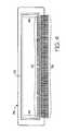
- FIG. 2illustrates an SDRAM chip within a lead frame as found in the prior art.
- FIGS. 3 a and 3 bportray a first exemplary embodiment of the present invention.
- FIG. 4represents an embodiment of the present invention in cooperation with a lead frame.
- FIGS. 5 a and 5 bdemonstrate a second exemplary embodiment of the present invention.
- FIGS. 5 c and 5 dillustrate a third exemplary embodiment of the present invention.
- FIGS. 6 a and 6 bdepict a fourth exemplary embodiment of the present invention.
- FIGS. 6 c and 6 ddepict a fifth exemplary embodiment of the present invention.
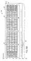
- FIG. 1depicts the architecture of an SDRAM 20 as it exists in the prior art.
- the SDRAM 20is fabricated on a die 22 and includes sixteen memory banks B 0 through B 15 .
- the shape of each bankis determined by the number and arrangement of component sub-arrays.
- each bankcomprises a row of sixteen sub-arrays.
- Bank B 0for example, comprises sub-arrays 000 through 015 .
- bank B 1comprises sub-arrays 100 through 115 .
- each bankis analogously numbered, ending with sub-arrays 1500 through 1515 comprising memory bank B 15 .
- Each sub-arraycontains a number of memory bit components and accompanying n/p channel sense amplifier circuitry 26 as well as row decoder circuitry 28 .
- the banks B 0 -B 15are also serviced by a first 64 ⁇ DC sense amp 30 and a second 64 ⁇ DC sense amp 32 . It should be noted that the size and number of DC sense amps can vary based on the compression rate desired.
- Column decoder circuitry 34is located next to the DC sense amps 30 and 32 ; and a column select line 36 extends from the column decoder circuitry 34 through all of the memory banks B 0 -B 15 .
- Logic circuitryis located in a region 38 on the other side of the DC sense amps 30 and 32 relative to the memory banks B 0 -B 15 .
- Bond pads 40are placed on the perimeter of the die 22 to allow easy access.
- the term “bond pad”includes any conductive surface configured to permit temporary or permanent electrical communication with a circuit or node.
- bond pad 40 Ais defined to be coupled to sub-arrays 000 , 100 , 200 , 300 , 400 , through 1500 .
- Access pad 40 Gis coupled to sub-arrays 006 through 1506 .
- Access pad 40 Pis defined to be coupled to sub-arrays 015 through 1515 .
- each access padassociated with a corresponding column comprising one sub-array from every bank.
- these sixteen access padsare located near their respective sub-arrays. It should be noted that, in FIG. 1, the group of sub-arrays 000 through 1500 is highlighted in bold for purposes of indicating the common association those sub-arrays have with a particular access pad (such as 40 A, for these sub-arrays). Groups 006 - 1506 and 015 - 1515 are similarly highlighted.
- Other bond pads 40representing additional input and output terminals for communicating with the die 22 , are placed in the remaining available spaces on the die 22 , which may include more than one side of the die 22 .
- Packaging of the die 22may be influenced by the fact that the internal circuitry of the die 22 will be interacting with a data bus.
- the die 22can be placed within a lead frame wherein the conductive leads 48 , 50 extend from the die 22 and eventually orient in one direction in anticipation of connecting to the data bus.
- bond pads 40 that are on the die's near side 42the side that will be closest to the external device—require only relatively short conductive leads 48 .
- bond pads 40 along the sides 44 , 46 contiguous to the near side 42require longer conductive leads 50 .
- the longer conductive leads 50will take a longer time to transmit any signals.
- inductance of the longer conductive leads 50will be greater than inductance of the shorter conductive leads 48 .
- FIGS. 3 a and 3 billustrate one embodiment of the current invention that solves these problems.
- the memory banksare separated into discontiguous portions.
- the columnar arrangement of sub-arrays, one from each bankis retained, and the columns are rotated ninety degrees relative to the configuration addressed above.
- the columnsare now parallel to the near side 42 .
- the sixteen sub-arrays associated with access pad 40 A( 000 through 1500 ) extended along contiguous side 44 in the prior art die depicted in FIG. 1 .
- this group of sub-arrays commonly coupled to access pad 40 Ais highlighted to show the new orientation of the sub-arrays and of the group in general.
- this group of sub-arraysnow extends along the near side 42 . While this group of sub-arrays 000 through 1500 is still relatively near contiguous side 44 , this is not necessary for purposes of the current invention; this group could occupy any of the columnar positions depicted in FIG. 2 . Regardless of the particular position of the columns, it is preferred that their respective access pad remain relatively close by.
- each sub-arrayis now oriented perpendicular to the near side 42 of the die 22 .
- Column decoder devices in this embodimentinclude a first modified column decoder circuit 60 interposed between a 700 series of sub-arrays ( 700 to 703 ) and an 800 series of sub-arrays ( 800 - 803 ).
- a first modified column select line 62extends from the first modified column decoder circuit 60 through sub-arrays 700 to 000 .
- a second modified column select line 64extends from the first modified column decoder circuit 60 through sub-arrays 800 to 1500 .
- This embodimentalso includes three other similarly configured modified column decoder circuits 66 , 61 , and 67 , each with their own modified column select lines 68 and 70 , 63 and 65 , and 69 and 71 , respectively.
- this embodiment of the present inventionuses four 32 ⁇ DC sense amps 52 , 54 , 56 , and 58 .
- the size and number of DC sense ampsmerely affect data compression and no one DC sense amp configuration is required for any embodiment of the current invention.
- the columnsare further arranged in groups of four. In doing so, this embodiment partially retains some of the bank continuity found in the prior art. For example, the sub-array sequence 000 , 001 , 002 , and 003 of Bank 0 remain contiguous. The Bank 0 sequence continues in the next four rotated columns with sub-arrays 004 , 005 , 006 , and 007 remaining next to each other. These intervals of bank continuity apply to the other memory banks as well and aid in minimizing the complexity of row decoder and column decoder circuitry. Arranging the columns in groups of four also means that certain columns will be further away from the near side 42 than other columns.
- this arrangement of rotated columnsallows for altering the dimensions of the die 22 .
- the near side 42be extended to a length commensurate with the data bus, but the contiguous sides 44 and 46 may also be shortened.
- extending the near side 42provides chip space for the bond pads 40 that had been along the contiguous sides 44 , 46 in the prior architecture.
- FIG. 4demonstrates the result of this architecture: when the die 22 is attached to a lead frame 76 having conductive leads on only one side, the die's formation accommodates short conductive leads 78 of uniform length. Packaging the die 22 with this lead frame 76 , in turn, allows for fast operation of the die 22 in conjunction with a device having a relatively large number of data terminals, such as a wide data bus.
- FIGS. 5 a and 5 bdemonstrate that, although the sub-arrays are rotated ninety degrees as in FIGS. 3 a and 3 b , it is not necessary to retain the columnar arrangement of the previous embodiment. Instead of the 16 ⁇ 1 columns, the sub-arrays in FIGS. 5 a and 5 b have been grouped into 4 ⁇ 4 associations. As demonstrated in the previous embodiment, there is a repetition of the sub-array pattern at continuous intervals. In the embodiment shown in FIGS. 5 a and 5 b , sequential sub-arrays of a particular bank are separated by sub-arrays of other banks.
- Sub-arrays 000 and 001 of Bank 0are separated by sub-arrays 400 , 800 , and 1200 . As further demonstrated in the previous embodiment, it is still preferred to configure the access pads near their respective grouping. Nevertheless, because the associated sub-arrays in FIGS. 3 a and 3 b extend along one dimension and include one sub-array from every bank, there is more sharing of row decoder circuitry 28 as well as column select circuitry 62 , 64 , 68 , 70 , 63 , 65 , 69 , and 71 in that embodiment than in the more fragmented sub-array groupings depicted in FIGS. 5 a and 5 b . Accordingly, the embodiment in FIGS. 3 a and 3 b is the more preferred embodiment of the two. FIGS. 5 c and 5 d represent an alternate configuration of 4 ⁇ 4 associations.
- FIGS. 6 a and 6 bThere are also alternative embodiments that do not involve rotating the orientation of the sub-arrays, as demonstrated in FIGS. 6 a and 6 b .
- the die 22 in FIGS. 6 a and 6 bhas a memory configuration only eight sub-arrays “deep.” Further, the sub-arrays are gathered into 8 ⁇ 2 groupings, again with one sub-array from every bank in each group and with each group associated with a particular access pad. Moreover, each group is oriented perpendicular to the near side 42 of die 22 .
- Group 90has been defined to contain sub-arrays 000 through 1500 , group 92 contains sub-arrays 001 through 1501 , and group 94 contains sub-arrays 002 through 1502 . While no particular order of groups is required, it is noteworthy in this embodiment that the sub-arrays 800 through 1500 in group 90 are next to sub-arrays 801 through 1501 in group 92 . In effect, groups 90 and 92 could be considered “mirror images” of each other. This mirror image configuration is useful in compressing data for test modes and in maximizing the opportunity to share row decoder circuitry 28 . It can further be seen in FIGS.
- group 94is a mirror image of group 92 , wherein sub-arrays 002 through 702 are respectively contiguous to sub-arrays 001 through 701 . While these mirror image configurations are preferable in a die architecture having 8 ⁇ 2 sub-array groupings, they are not necessary to realize the current invention. As in other embodiments, this one has a die shape capable of including bond pads in a configuration accommodatable to communication with an external device, with a memory arrangement generally conforming to the die shape.
- FIGS. 6 a and 6 balso benefits from four 32 ⁇ DC sense amps 80 , 81 , 82 , and 83 . Further, there are two column decoder circuits 84 and 85 , each associated with respective column select lines 86 and 87 . Unlike the previous embodiments, however, each sub-array is oriented parallel to the near side 42 of the die 22 .
- FIGS. 6 c and 6 drepresent an alternate configuration of 8 ⁇ 2 associations or groupings of sub-arrays.
- embodiments of die architecture covered by this inventionneed not be restricted to placing bond pads on only one side of a die. It may be desirable in certain applications to use a lead frame having conductive leads facing two or more sides of a die. Die architectures included within the scope of this invention could locate the die's bond pads to allow for conductive leads of a uniform length and, more specifically, a uniformly short length on all relevant sides. In addition, the dimensions of the memory banks could be adapted to conform to a particular die's requirements.
- the 4 ⁇ 4 banks of rotated sub-arrayscan be replaced with an embodiment having a series of rotated sub-arrays grouped into 2 ⁇ 8 banks. Accordingly, the invention is not limited except as stated in the claims.
Landscapes
- Engineering & Computer Science (AREA)
- Microelectronics & Electronic Packaging (AREA)
- Dram (AREA)
Abstract
Description
Claims (6)
Priority Applications (4)
| Application Number | Priority Date | Filing Date | Title |
|---|---|---|---|
| US09/652,839US6320779B1 (en) | 1998-02-13 | 2000-08-31 | Die architecture accommodating high-speed semiconductor devices |
| US09/964,134US6430075B2 (en) | 1998-02-13 | 2001-09-25 | Die architecture accommodating high-speed semiconductor devices |
| US10/017,515US6545894B2 (en) | 1998-02-13 | 2001-12-11 | Die architecture accommodating high-speed semiconductor devices |
| US10/017,517US6501669B2 (en) | 1998-02-13 | 2001-12-11 | Die architecture accommodating high-speed semiconductor devices |
Applications Claiming Priority (4)
| Application Number | Priority Date | Filing Date | Title |
|---|---|---|---|
| US09/023,254US5936877A (en) | 1998-02-13 | 1998-02-13 | Die architecture accommodating high-speed semiconductor devices |
| US09/301,643US5995402A (en) | 1998-02-13 | 1999-04-28 | Die architecture accommodating high-speed semiconductor devices |
| US09/439,972US6144575A (en) | 1998-02-13 | 1999-11-12 | Die architecture accommodating high-speed semiconductor devices |
| US09/652,839US6320779B1 (en) | 1998-02-13 | 2000-08-31 | Die architecture accommodating high-speed semiconductor devices |
Related Parent Applications (1)
| Application Number | Title | Priority Date | Filing Date |
|---|---|---|---|
| US09/439,972DivisionUS6144575A (en) | 1998-02-13 | 1999-11-12 | Die architecture accommodating high-speed semiconductor devices |
Related Child Applications (2)
| Application Number | Title | Priority Date | Filing Date |
|---|---|---|---|
| US09694134Continuation | 2001-09-25 | ||
| US09/964,134ContinuationUS6430075B2 (en) | 1998-02-13 | 2001-09-25 | Die architecture accommodating high-speed semiconductor devices |
Publications (1)
| Publication Number | Publication Date |
|---|---|
| US6320779B1true US6320779B1 (en) | 2001-11-20 |
Family
ID=21813988
Family Applications (15)
| Application Number | Title | Priority Date | Filing Date |
|---|---|---|---|
| US09/023,254Expired - LifetimeUS5936877A (en) | 1998-02-13 | 1998-02-13 | Die architecture accommodating high-speed semiconductor devices |
| US09/301,643Expired - LifetimeUS5995402A (en) | 1998-02-13 | 1999-04-28 | Die architecture accommodating high-speed semiconductor devices |
| US09/439,972Expired - LifetimeUS6144575A (en) | 1998-02-13 | 1999-11-12 | Die architecture accommodating high-speed semiconductor devices |
| US09/652,586Expired - LifetimeUS6301142B1 (en) | 1998-02-13 | 2000-08-31 | Die architecture accomodating high-speed semiconductor devices |
| US09/652,996Expired - LifetimeUS6327167B1 (en) | 1998-02-13 | 2000-08-31 | Die architecture accommodating high-speed semiconductor devices |
| US09/652,584Expired - LifetimeUS6438011B1 (en) | 1998-02-13 | 2000-08-31 | Die architecture accommodating high-speed semiconductor devices |
| US09/652,587Expired - LifetimeUS6314012B1 (en) | 1998-02-13 | 2000-08-31 | Die architecture accommodating high-speed semiconductor devices |
| US09/652,578Expired - LifetimeUS6301141B1 (en) | 1998-02-13 | 2000-08-31 | Die architecture accommodating high-speed semiconductor devices |
| US09/652,839Expired - LifetimeUS6320779B1 (en) | 1998-02-13 | 2000-08-31 | Die architecture accommodating high-speed semiconductor devices |
| US09/964,134Expired - LifetimeUS6430075B2 (en) | 1998-02-13 | 2001-09-25 | Die architecture accommodating high-speed semiconductor devices |
| US09/999,094AbandonedUS20020060921A1 (en) | 1998-02-13 | 2001-10-30 | Die architecture accommodating high-speed semiconductor devices |
| US10/007,571Expired - LifetimeUS6504743B2 (en) | 1998-02-13 | 2001-11-07 | Die architecture accommodating high-speed semiconductor devices |
| US10/005,087Expired - LifetimeUS6498740B2 (en) | 1998-02-13 | 2001-12-04 | Die architecture accommodating high-speed semiconductor devices |
| US10/017,515Expired - LifetimeUS6545894B2 (en) | 1998-02-13 | 2001-12-11 | Die architecture accommodating high-speed semiconductor devices |
| US10/017,517Expired - LifetimeUS6501669B2 (en) | 1998-02-13 | 2001-12-11 | Die architecture accommodating high-speed semiconductor devices |
Family Applications Before (8)
| Application Number | Title | Priority Date | Filing Date |
|---|---|---|---|
| US09/023,254Expired - LifetimeUS5936877A (en) | 1998-02-13 | 1998-02-13 | Die architecture accommodating high-speed semiconductor devices |
| US09/301,643Expired - LifetimeUS5995402A (en) | 1998-02-13 | 1999-04-28 | Die architecture accommodating high-speed semiconductor devices |
| US09/439,972Expired - LifetimeUS6144575A (en) | 1998-02-13 | 1999-11-12 | Die architecture accommodating high-speed semiconductor devices |
| US09/652,586Expired - LifetimeUS6301142B1 (en) | 1998-02-13 | 2000-08-31 | Die architecture accomodating high-speed semiconductor devices |
| US09/652,996Expired - LifetimeUS6327167B1 (en) | 1998-02-13 | 2000-08-31 | Die architecture accommodating high-speed semiconductor devices |
| US09/652,584Expired - LifetimeUS6438011B1 (en) | 1998-02-13 | 2000-08-31 | Die architecture accommodating high-speed semiconductor devices |
| US09/652,587Expired - LifetimeUS6314012B1 (en) | 1998-02-13 | 2000-08-31 | Die architecture accommodating high-speed semiconductor devices |
| US09/652,578Expired - LifetimeUS6301141B1 (en) | 1998-02-13 | 2000-08-31 | Die architecture accommodating high-speed semiconductor devices |
Family Applications After (6)
| Application Number | Title | Priority Date | Filing Date |
|---|---|---|---|
| US09/964,134Expired - LifetimeUS6430075B2 (en) | 1998-02-13 | 2001-09-25 | Die architecture accommodating high-speed semiconductor devices |
| US09/999,094AbandonedUS20020060921A1 (en) | 1998-02-13 | 2001-10-30 | Die architecture accommodating high-speed semiconductor devices |
| US10/007,571Expired - LifetimeUS6504743B2 (en) | 1998-02-13 | 2001-11-07 | Die architecture accommodating high-speed semiconductor devices |
| US10/005,087Expired - LifetimeUS6498740B2 (en) | 1998-02-13 | 2001-12-04 | Die architecture accommodating high-speed semiconductor devices |
| US10/017,515Expired - LifetimeUS6545894B2 (en) | 1998-02-13 | 2001-12-11 | Die architecture accommodating high-speed semiconductor devices |
| US10/017,517Expired - LifetimeUS6501669B2 (en) | 1998-02-13 | 2001-12-11 | Die architecture accommodating high-speed semiconductor devices |
Country Status (1)
| Country | Link |
|---|---|
| US (15) | US5936877A (en) |
Cited By (4)
| Publication number | Priority date | Publication date | Assignee | Title |
|---|---|---|---|---|
| US6430075B2 (en) | 1998-02-13 | 2002-08-06 | Micron Technology, Inc. | Die architecture accommodating high-speed semiconductor devices |
| US6571380B2 (en) | 2001-07-12 | 2003-05-27 | Micron Technology, Inc. | Integrated circuit with layout matched high speed lines |
| WO2003085672A1 (en)* | 2002-04-10 | 2003-10-16 | Hynix Semiconductor Inc. | Memory chip architecture having non-rectangular memory banks and method for arranging memory banks |
| US20070096302A1 (en)* | 2005-10-31 | 2007-05-03 | Josef Schuster | Semiconductor memory module |
Families Citing this family (16)
| Publication number | Priority date | Publication date | Assignee | Title |
|---|---|---|---|---|
| US6188595B1 (en) | 1998-06-30 | 2001-02-13 | Micron Technology, Inc. | Memory architecture and addressing for optimized density in integrated circuit package or on circuit board |
| US6445603B1 (en)* | 2000-08-21 | 2002-09-03 | Micron Technology, Inc. | Architecture, package orientation and assembly of memory devices |
| JP3433731B2 (en)* | 2000-11-10 | 2003-08-04 | セイコーエプソン株式会社 | I/O cell layout method and semiconductor device |
| KR100380409B1 (en)* | 2001-01-18 | 2003-04-11 | 삼성전자주식회사 | Pad Arrangement in Semiconductor Memory Device AND Method for driving the Semiconductor Device |
| WO2003014224A1 (en) | 2001-08-03 | 2003-02-20 | Toray Industries, Inc. | Resin composition and molded article, film, and fiber each comprising the same |
| JP2003117053A (en)* | 2001-10-12 | 2003-04-22 | Aruze Corp | Game server, game management method and game machine |
| US6649773B2 (en) | 2002-03-22 | 2003-11-18 | General Electric Company | Method for the manufacture of halophthalic acids and anhydrides |
| US7464282B1 (en) | 2003-09-03 | 2008-12-09 | T-Ram Semiconductor, Inc. | Apparatus and method for producing dummy data and output clock generator using same |
| US6891774B1 (en) | 2003-09-03 | 2005-05-10 | T-Ram, Inc. | Delay line and output clock generator using same |
| US6947349B1 (en) | 2003-09-03 | 2005-09-20 | T-Ram, Inc. | Apparatus and method for producing an output clock pulse and output clock generator using same |
| US7089439B1 (en) | 2003-09-03 | 2006-08-08 | T-Ram, Inc. | Architecture and method for output clock generation on a high speed memory device |
| US7509594B2 (en)* | 2005-07-06 | 2009-03-24 | Sandisk Il Ltd. | Method of selling integrated circuit dies for multi-chip packages |
| KR20090038543A (en)* | 2007-10-16 | 2009-04-21 | 주식회사 하이닉스반도체 | Semiconductor memory device |
| CN102567557B (en)* | 2010-12-20 | 2014-07-09 | 国际商业机器公司 | Method and device for constructing clock tree used for integrated circuit design |
| US8922087B1 (en) | 2013-08-26 | 2014-12-30 | Norman P Rittenhouse | High efficiency low torque ripple multi-phase permanent magnet machine |
| TWI769094B (en)* | 2021-10-07 | 2022-06-21 | 瑞昱半導體股份有限公司 | Multi-die package |
Citations (20)
| Publication number | Priority date | Publication date | Assignee | Title |
|---|---|---|---|---|
| US4660174A (en) | 1983-06-29 | 1987-04-21 | Fujitsu Limited | Semiconductor memory device having divided regular circuits |
| US4974053A (en) | 1988-10-06 | 1990-11-27 | Mitsubishi Denki Kabushiki Kaisha | Semiconductor device for multiple packaging configurations |
| US5073816A (en) | 1989-08-14 | 1991-12-17 | Inmos Limited | Packaging semiconductor chips |
| US5109265A (en) | 1989-11-24 | 1992-04-28 | Siemens Aktiengesellschaft | Semiconductor memory with connection pads disposed in the interior |
| US5142492A (en) | 1989-10-05 | 1992-08-25 | Kabushiki Kaisha Toshiba | Semiconductor memory device |
| US5150330A (en) | 1990-01-24 | 1992-09-22 | Vlsi Technology, Inc. | Interblock dispersed-word memory architecture |
| US5231607A (en) | 1989-10-19 | 1993-07-27 | Kabushiki Kaisha Toshiba | Semiconductor memory device |
| US5251168A (en) | 1991-07-31 | 1993-10-05 | Texas Instruments Incorporated | Boundary cells for improving retention time in memory devices |
| US5287000A (en) | 1987-10-20 | 1994-02-15 | Hitachi, Ltd. | Resin-encapsulated semiconductor memory device useful for single in-line packages |
| US5293334A (en) | 1990-11-30 | 1994-03-08 | Kabushiki Kaisha Tobshiba | Pattern layout of power source lines in semiconductor memory device |
| US5357478A (en) | 1990-10-05 | 1994-10-18 | Mitsubishi Denki Kabushiki Kaisha | Semiconductor integrated circuit device including a plurality of cell array blocks |
| US5408129A (en) | 1990-04-18 | 1995-04-18 | Rambus, Inc. | Integrated circuit I/O using a high performance bus interface |
| US5636174A (en) | 1996-01-11 | 1997-06-03 | Cirrus Logic, Inc. | Fast cycle time-low latency dynamic random access memories and systems and methods using the same |
| US5812490A (en)* | 1997-02-27 | 1998-09-22 | Mitsubishi Denki Kabushiki Kaisha | Synchronous dynamic semiconductor memory device capable of restricting delay of data output timing |
| US5831924A (en)* | 1995-09-07 | 1998-11-03 | Mitsubishi Denki Kabushiki Kaisha | Synchronous semiconductor memory device having a plurality of banks distributed in a plurality of memory arrays |
| US5838604A (en) | 1996-09-17 | 1998-11-17 | Fujitsu Limited | Semiconductor memory device with an increased band width |
| US5880987A (en) | 1997-07-14 | 1999-03-09 | Micron Technology, Inc. | Architecture and package orientation for high speed memory devices |
| US5936877A (en) | 1998-02-13 | 1999-08-10 | Micron Technology, Inc. | Die architecture accommodating high-speed semiconductor devices |
| US5943285A (en) | 1996-08-05 | 1999-08-24 | Kabushiki Kaisha Toshiba | Arrangement of memory blocks and pads |
| US6104627A (en)* | 1996-04-23 | 2000-08-15 | Oki Electric Industry Co., Ltd. | Semiconductor memory device |
Family Cites Families (3)
| Publication number | Priority date | Publication date | Assignee | Title |
|---|---|---|---|---|
| US6388314B1 (en) | 1995-08-17 | 2002-05-14 | Micron Technology, Inc. | Single deposition layer metal dynamic random access memory |
| US5903491A (en) | 1997-06-09 | 1999-05-11 | Micron Technology, Inc. | Single deposition layer metal dynamic random access memory |
| US5978302A (en)* | 1998-05-13 | 1999-11-02 | Micron Technology, Inc. | Multi-bank architecture for a wide I/O DRAM |
- 1998
- 1998-02-13USUS09/023,254patent/US5936877A/ennot_activeExpired - Lifetime
- 1999
- 1999-04-28USUS09/301,643patent/US5995402A/ennot_activeExpired - Lifetime
- 1999-11-12USUS09/439,972patent/US6144575A/ennot_activeExpired - Lifetime
- 2000
- 2000-08-31USUS09/652,586patent/US6301142B1/ennot_activeExpired - Lifetime
- 2000-08-31USUS09/652,996patent/US6327167B1/ennot_activeExpired - Lifetime
- 2000-08-31USUS09/652,584patent/US6438011B1/ennot_activeExpired - Lifetime
- 2000-08-31USUS09/652,587patent/US6314012B1/ennot_activeExpired - Lifetime
- 2000-08-31USUS09/652,578patent/US6301141B1/ennot_activeExpired - Lifetime
- 2000-08-31USUS09/652,839patent/US6320779B1/ennot_activeExpired - Lifetime
- 2001
- 2001-09-25USUS09/964,134patent/US6430075B2/ennot_activeExpired - Lifetime
- 2001-10-30USUS09/999,094patent/US20020060921A1/ennot_activeAbandoned
- 2001-11-07USUS10/007,571patent/US6504743B2/ennot_activeExpired - Lifetime
- 2001-12-04USUS10/005,087patent/US6498740B2/ennot_activeExpired - Lifetime
- 2001-12-11USUS10/017,515patent/US6545894B2/ennot_activeExpired - Lifetime
- 2001-12-11USUS10/017,517patent/US6501669B2/ennot_activeExpired - Lifetime
Patent Citations (22)
| Publication number | Priority date | Publication date | Assignee | Title |
|---|---|---|---|---|
| US4660174A (en) | 1983-06-29 | 1987-04-21 | Fujitsu Limited | Semiconductor memory device having divided regular circuits |
| US5287000A (en) | 1987-10-20 | 1994-02-15 | Hitachi, Ltd. | Resin-encapsulated semiconductor memory device useful for single in-line packages |
| US4974053A (en) | 1988-10-06 | 1990-11-27 | Mitsubishi Denki Kabushiki Kaisha | Semiconductor device for multiple packaging configurations |
| US5073816A (en) | 1989-08-14 | 1991-12-17 | Inmos Limited | Packaging semiconductor chips |
| US5142492A (en) | 1989-10-05 | 1992-08-25 | Kabushiki Kaisha Toshiba | Semiconductor memory device |
| US5231607A (en) | 1989-10-19 | 1993-07-27 | Kabushiki Kaisha Toshiba | Semiconductor memory device |
| US5109265A (en) | 1989-11-24 | 1992-04-28 | Siemens Aktiengesellschaft | Semiconductor memory with connection pads disposed in the interior |
| US5150330A (en) | 1990-01-24 | 1992-09-22 | Vlsi Technology, Inc. | Interblock dispersed-word memory architecture |
| US5408129A (en) | 1990-04-18 | 1995-04-18 | Rambus, Inc. | Integrated circuit I/O using a high performance bus interface |
| US5357478A (en) | 1990-10-05 | 1994-10-18 | Mitsubishi Denki Kabushiki Kaisha | Semiconductor integrated circuit device including a plurality of cell array blocks |
| US5293334A (en) | 1990-11-30 | 1994-03-08 | Kabushiki Kaisha Tobshiba | Pattern layout of power source lines in semiconductor memory device |
| US5251168A (en) | 1991-07-31 | 1993-10-05 | Texas Instruments Incorporated | Boundary cells for improving retention time in memory devices |
| US5831924A (en)* | 1995-09-07 | 1998-11-03 | Mitsubishi Denki Kabushiki Kaisha | Synchronous semiconductor memory device having a plurality of banks distributed in a plurality of memory arrays |
| US5636174A (en) | 1996-01-11 | 1997-06-03 | Cirrus Logic, Inc. | Fast cycle time-low latency dynamic random access memories and systems and methods using the same |
| US6104627A (en)* | 1996-04-23 | 2000-08-15 | Oki Electric Industry Co., Ltd. | Semiconductor memory device |
| US5943285A (en) | 1996-08-05 | 1999-08-24 | Kabushiki Kaisha Toshiba | Arrangement of memory blocks and pads |
| US5838604A (en) | 1996-09-17 | 1998-11-17 | Fujitsu Limited | Semiconductor memory device with an increased band width |
| US5812490A (en)* | 1997-02-27 | 1998-09-22 | Mitsubishi Denki Kabushiki Kaisha | Synchronous dynamic semiconductor memory device capable of restricting delay of data output timing |
| US5880987A (en) | 1997-07-14 | 1999-03-09 | Micron Technology, Inc. | Architecture and package orientation for high speed memory devices |
| US5936877A (en) | 1998-02-13 | 1999-08-10 | Micron Technology, Inc. | Die architecture accommodating high-speed semiconductor devices |
| US5995402A (en) | 1998-02-13 | 1999-11-30 | Micron Technology, Inc. | Die architecture accommodating high-speed semiconductor devices |
| US6144575A (en) | 1998-02-13 | 2000-11-07 | Micron Technology, Inc. | Die architecture accommodating high-speed semiconductor devices |
Cited By (18)
| Publication number | Priority date | Publication date | Assignee | Title |
|---|---|---|---|---|
| US6430075B2 (en) | 1998-02-13 | 2002-08-06 | Micron Technology, Inc. | Die architecture accommodating high-speed semiconductor devices |
| US6498740B2 (en) | 1998-02-13 | 2002-12-24 | Micron Technology, Inc. | Die architecture accommodating high-speed semiconductor devices |
| US6501669B2 (en) | 1998-02-13 | 2002-12-31 | Micron Technology, Inc. | Die architecture accommodating high-speed semiconductor devices |
| US6504743B2 (en) | 1998-02-13 | 2003-01-07 | Micron Technology, Inc. | Die architecture accommodating high-speed semiconductor devices |
| US6545894B2 (en) | 1998-02-13 | 2003-04-08 | Micron Technology, Inc. | Die architecture accommodating high-speed semiconductor devices |
| US7082581B2 (en) | 2001-07-12 | 2006-07-25 | Micron Technology, Inc. | Integrated circuit with layout matched high speed lines |
| US20030126574A1 (en)* | 2001-07-12 | 2003-07-03 | Micron Technology, Inc. | Integrated circuit with layout matched high speed lines |
| US20030131322A1 (en)* | 2001-07-12 | 2003-07-10 | Micron Technology, Inc. | Integrated circuit with layout matched high speed lines |
| US6810512B2 (en) | 2001-07-12 | 2004-10-26 | Micron Technology, Inc. | Integrated circuit with layout matched high speed lines |
| US7028282B2 (en) | 2001-07-12 | 2006-04-11 | Micron Technology, Inc. | Integrated circuit with layout matched high speed lines |
| US6571380B2 (en) | 2001-07-12 | 2003-05-27 | Micron Technology, Inc. | Integrated circuit with layout matched high speed lines |
| WO2003085672A1 (en)* | 2002-04-10 | 2003-10-16 | Hynix Semiconductor Inc. | Memory chip architecture having non-rectangular memory banks and method for arranging memory banks |
| US20050226089A1 (en)* | 2002-04-10 | 2005-10-13 | Jun-Hyun Chun | Memory chip architecture having non-rectangular memory banks and method for arranging memory banks |
| US7236420B2 (en) | 2002-04-10 | 2007-06-26 | Hynix Semiconductor Inc. | Memory chip architecture having non-rectangular memory banks and method for arranging memory banks |
| US20080002508A1 (en)* | 2002-04-10 | 2008-01-03 | Jun-Hyun Chun | Memory chip architecture having non-rectangular memory banks and method for arranging memory banks |
| US8305833B2 (en) | 2002-04-10 | 2012-11-06 | 658868 N.B. Inc. | Memory chip architecture having non-rectangular memory banks and method for arranging memory banks |
| US20070096302A1 (en)* | 2005-10-31 | 2007-05-03 | Josef Schuster | Semiconductor memory module |
| US7315454B2 (en)* | 2005-10-31 | 2008-01-01 | Infineon Technologies Ag | Semiconductor memory module |
Also Published As
| Publication number | Publication date |
|---|---|
| US6327167B1 (en) | 2001-12-04 |
| US6301142B1 (en) | 2001-10-09 |
| US20020075716A1 (en) | 2002-06-20 |
| US6498740B2 (en) | 2002-12-24 |
| US20020060921A1 (en) | 2002-05-23 |
| US6504743B2 (en) | 2003-01-07 |
| US20020008985A1 (en) | 2002-01-24 |
| US6438011B1 (en) | 2002-08-20 |
| US6301141B1 (en) | 2001-10-09 |
| US6144575A (en) | 2000-11-07 |
| US5995402A (en) | 1999-11-30 |
| US6430075B2 (en) | 2002-08-06 |
| US20020039304A1 (en) | 2002-04-04 |
| US5936877A (en) | 1999-08-10 |
| US20020073392A1 (en) | 2002-06-13 |
| US20020041508A1 (en) | 2002-04-11 |
| US6501669B2 (en) | 2002-12-31 |
| US6545894B2 (en) | 2003-04-08 |
| US6314012B1 (en) | 2001-11-06 |
Similar Documents
| Publication | Publication Date | Title |
|---|---|---|
| US6320779B1 (en) | Die architecture accommodating high-speed semiconductor devices | |
| US7626248B2 (en) | Semiconductor package with a controlled impedance bus | |
| US20020008255A1 (en) | Semiconductor device | |
| WO1997007543A1 (en) | Single deposition layer metal dynamic random access memory | |
| JPH03133174A (en) | Semiconductor storage device | |
| US20070246835A1 (en) | Semiconductor device | |
| US6229726B1 (en) | Integrated circuit chip having multiple package options | |
| US4575744A (en) | Interconnection of elements on integrated circuit substrate | |
| US7236420B2 (en) | Memory chip architecture having non-rectangular memory banks and method for arranging memory banks | |
| US6632705B1 (en) | Memory modules and packages using different orientations and terminal assignments | |
| US20070090500A1 (en) | Housed DRAM chip for high-speed applications | |
| US6147924A (en) | Arrangement of data input/output circuits for use in a semiconductor memory device | |
| US6879036B2 (en) | Semiconductor memory device and method of manufacturing semiconductor device with chip on chip structure | |
| KR100498448B1 (en) | Synchronous semiconductor device and Method for minimizing coupling between data bus | |
| JP4111313B2 (en) | Semiconductor memory device | |
| KR20030081033A (en) | Memory device with non-quadrangular memory bank | |
| KR20000031211A (en) | Semiconductor memory device for reducing chip area due to effective arrangement of banks | |
| JPH02146768A (en) | Semiconductor storage device |
Legal Events
| Date | Code | Title | Description |
|---|---|---|---|
| STCF | Information on status: patent grant | Free format text:PATENTED CASE | |
| FPAY | Fee payment | Year of fee payment:4 | |
| FPAY | Fee payment | Year of fee payment:8 | |
| FPAY | Fee payment | Year of fee payment:12 | |
| AS | Assignment | Owner name:U.S. BANK NATIONAL ASSOCIATION, AS COLLATERAL AGENT, CALIFORNIA Free format text:SECURITY INTEREST;ASSIGNOR:MICRON TECHNOLOGY, INC.;REEL/FRAME:038669/0001 Effective date:20160426 Owner name:U.S. BANK NATIONAL ASSOCIATION, AS COLLATERAL AGEN Free format text:SECURITY INTEREST;ASSIGNOR:MICRON TECHNOLOGY, INC.;REEL/FRAME:038669/0001 Effective date:20160426 | |
| AS | Assignment | Owner name:MORGAN STANLEY SENIOR FUNDING, INC., AS COLLATERAL AGENT, MARYLAND Free format text:PATENT SECURITY AGREEMENT;ASSIGNOR:MICRON TECHNOLOGY, INC.;REEL/FRAME:038954/0001 Effective date:20160426 Owner name:MORGAN STANLEY SENIOR FUNDING, INC., AS COLLATERAL Free format text:PATENT SECURITY AGREEMENT;ASSIGNOR:MICRON TECHNOLOGY, INC.;REEL/FRAME:038954/0001 Effective date:20160426 | |
| AS | Assignment | Owner name:U.S. BANK NATIONAL ASSOCIATION, AS COLLATERAL AGENT, CALIFORNIA Free format text:CORRECTIVE ASSIGNMENT TO CORRECT THE REPLACE ERRONEOUSLY FILED PATENT #7358718 WITH THE CORRECT PATENT #7358178 PREVIOUSLY RECORDED ON REEL 038669 FRAME 0001. ASSIGNOR(S) HEREBY CONFIRMS THE SECURITY INTEREST;ASSIGNOR:MICRON TECHNOLOGY, INC.;REEL/FRAME:043079/0001 Effective date:20160426 Owner name:U.S. BANK NATIONAL ASSOCIATION, AS COLLATERAL AGEN Free format text:CORRECTIVE ASSIGNMENT TO CORRECT THE REPLACE ERRONEOUSLY FILED PATENT #7358718 WITH THE CORRECT PATENT #7358178 PREVIOUSLY RECORDED ON REEL 038669 FRAME 0001. ASSIGNOR(S) HEREBY CONFIRMS THE SECURITY INTEREST;ASSIGNOR:MICRON TECHNOLOGY, INC.;REEL/FRAME:043079/0001 Effective date:20160426 | |
| AS | Assignment | Owner name:MICRON TECHNOLOGY, INC., IDAHO Free format text:RELEASE BY SECURED PARTY;ASSIGNOR:U.S. BANK NATIONAL ASSOCIATION, AS COLLATERAL AGENT;REEL/FRAME:047243/0001 Effective date:20180629 | |
| AS | Assignment | Owner name:MICRON TECHNOLOGY, INC., IDAHO Free format text:RELEASE BY SECURED PARTY;ASSIGNOR:MORGAN STANLEY SENIOR FUNDING, INC., AS COLLATERAL AGENT;REEL/FRAME:050937/0001 Effective date:20190731 |