US6320394B1 - Capacitive distance sensor - Google Patents
Capacitive distance sensorDownload PDFInfo
- Publication number
- US6320394B1 US6320394B1US09/019,496US1949698AUS6320394B1US 6320394 B1US6320394 B1US 6320394B1US 1949698 AUS1949698 AUS 1949698AUS 6320394 B1US6320394 B1US 6320394B1
- Authority
- US
- United States
- Prior art keywords
- output
- amplifier
- input
- plate
- sensor
- Prior art date
- Legal status (The legal status is an assumption and is not a legal conclusion. Google has not performed a legal analysis and makes no representation as to the accuracy of the status listed.)
- Expired - Lifetime
Links
Images


Classifications
- G—PHYSICS
- G01—MEASURING; TESTING
- G01B—MEASURING LENGTH, THICKNESS OR SIMILAR LINEAR DIMENSIONS; MEASURING ANGLES; MEASURING AREAS; MEASURING IRREGULARITIES OF SURFACES OR CONTOURS
- G01B7/00—Measuring arrangements characterised by the use of electric or magnetic techniques
- G01B7/004—Measuring arrangements characterised by the use of electric or magnetic techniques for measuring coordinates of points
- G—PHYSICS
- G01—MEASURING; TESTING
- G01B—MEASURING LENGTH, THICKNESS OR SIMILAR LINEAR DIMENSIONS; MEASURING ANGLES; MEASURING AREAS; MEASURING IRREGULARITIES OF SURFACES OR CONTOURS
- G01B7/00—Measuring arrangements characterised by the use of electric or magnetic techniques
- G01B7/02—Measuring arrangements characterised by the use of electric or magnetic techniques for measuring length, width or thickness
- G01B7/023—Measuring arrangements characterised by the use of electric or magnetic techniques for measuring length, width or thickness for measuring distance between sensor and object
- G—PHYSICS
- G01—MEASURING; TESTING
- G01B—MEASURING LENGTH, THICKNESS OR SIMILAR LINEAR DIMENSIONS; MEASURING ANGLES; MEASURING AREAS; MEASURING IRREGULARITIES OF SURFACES OR CONTOURS
- G01B7/00—Measuring arrangements characterised by the use of electric or magnetic techniques
- G01B7/34—Measuring arrangements characterised by the use of electric or magnetic techniques for measuring roughness or irregularity of surfaces
- G—PHYSICS
- G06—COMPUTING OR CALCULATING; COUNTING
- G06V—IMAGE OR VIDEO RECOGNITION OR UNDERSTANDING
- G06V40/00—Recognition of biometric, human-related or animal-related patterns in image or video data
- G06V40/10—Human or animal bodies, e.g. vehicle occupants or pedestrians; Body parts, e.g. hands
- G06V40/12—Fingerprints or palmprints
- G06V40/13—Sensors therefor
- G06V40/1306—Sensors therefor non-optical, e.g. ultrasonic or capacitive sensing
Definitions
- the present inventionrelates to a capacitive distance sensor, in particular, a small-distance (micrometric to millimetric) sensor.
- Small-distance sensorsare used, among other things, as pressure, proximity, roughness, mechanical stress and acceleration sensors, for example, in integrated microphony and for acquiring fingerprints.
- known sensorsinclude various types, such as optical, piezoelectric, variable-conductance, thermal, ultrasonic and capacitive, the most promising of which in terms of precision, size, production and cost are capacitive sensors.
- Capacitive sensorsare based on the principle that the capacitance between two armatures is inversely proportional to the distance between them, so that, using the contacting dermal tissue itself as the second armature of the sensor capacitor, and by determining the capacitance, it is possible to locate the ridges and grooves of the fingerprint.
- Thisis the principle used in U.S. Pat. No. 5,325,442 to Knapp, which relates to a sensor comprising an array of elementary cells, each comprising a sensitive electrode and an electronic switching device.
- the electrodeis coated with dielectric material, such as passivation oxide or a polymer compound, onto which the epidermis is placed.
- a predetermined variation in potentialis applied to the electrode to induce at the terminals an appropriate variation in charge.
- the extent of variation in chargedepends on the capacitance associated with the electrode and is read by amplifying elements connected to the output of the device.
- the above patentsuggests a surface grid connected to a reference potential to appropriately bias the skin tissue.
- the capacitance between the armatures of a capacitorvaries in inverse proportion to the distance between the armatures, which therefore poses the problem of normalizing the resulting data.
- the capacitance being measuredis very small, as in the application in question, serious difficulty is encountered in detecting the charge and discriminating between the various intermediate charge levels corresponding to different grey levels of the image to be generated in the presence of a low signal/noise ratio.
- a preferred embodiment of the present inventionis directed to a capacitive distance sensor for measuring small distances.
- the distance sensorincludes a first armature positioned facing a second armature such that the first and second armatures define a distance to be measured therebetween and form a capacitive element therebetween.
- the distance sensoralso includes an amplifier having an input and an output. The capacitive element is connected between the input and the output to form a negative feedback branch.
- the detecting capacitorthe distance between the armatures of which is to be determined, is placed in a negative feedback loop, thus inverting between the denominator and the numerator the dependance of the output voltage on the distance between the armatures.
- a preferred embodiment of the present inventionis directed to a sensor device, integrated on a single semiconductor chip, that senses a distance between the sensor device and an object such as a human finger.
- the sensor deviceincludes first and second coplanar armatures positioned adjacent to the object to form first and second capacitances between the object and the first and second armatures, respectively.
- the sensor deviceincludes an amplifier having an input connected to the first armature and an output connected to the second armature to form a negative feedback branch that includes the first and second capacitances.
- Fingerprint and other biometric sensors formed in accordance with the present inventionwill have application in preventing the unauthorized use of cellular phones, laptop computers, automobiles, automated teller machines, credit/debit card readers, POS terminals, and smart cards. They are also useful in authenticating electronic financial transactions, personal e-mail, providing access to buildings, etc.
- Biometric identificationsuch as personal identification and authentication alternatives which could be accomplished by mounting a sensor as taught by the present invention include hand or finger shape, facial shape, and facial features.
- the sensor device of the present inventioncould be used for non-biometric sensing, such as handwriting detection, switch actuation, and any other device requiring sensitivity to object proximity.
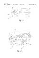
- FIG. 1shows a sensor device for acquiring personal feature scans, such as fingerprints.
- FIG. 2shows a detail of a cell of the sensor device shown in FIG. 1 .
- FIG. 3shows an electric equivalent of the cell shown in FIG. 2 .
- FIG. 4is an illustration showing a finger positioned on two adjacent cells of the sensor device shown in FIG. 1 .
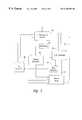
- FIG. 5is a block diagram of the sensor device shown in FIG. 1 .
- FIG. 6is a circuit diagram of one embodiment of the cell shown in FIG. 2 .
- FIG. 7is an image of a fingerprint obtained from the sensor device shown in FIG. 1 .
- FIG. 1shows a sensor device 1 , preferably embodied in an integrated chip, comprising a number of cells 2 arranged to form an array 3 and each constituting an elementary sensor.
- the simplicity of the individual cells 2enables the sensor device 1 to be implemented in integrated form on a single semiconductor chip.
- the sensor device 1also comprises a horizontal scanning stage 5 and a vertical scanning stage 6 for enabling one of the cells 2 at a time according to a predetermined scanning pattern.
- stages 5 , 6enable the outputs of the cells 2 sequentially, and comprise shift registers.
- other cell reading devicescould be employed, such as a random access decoder that reads addressed cells rather than sequentially scanning the cells 2 .
- the sensor device 1also comprises a supply and logic stage 7 , which supplies the components of the device with power (including the cells 2 ), feeds the necessary reference voltages, and controls the sequence of steps provided for (as explained in detail below).
- the supply and logic stage 7includes a voltage source 12 for generating a reference voltage variation ⁇ V R .
- a buffer 8is connected to the outputs of all the cells 2 , and supplies sequentially, at output 10 of the sensor array 3 , the signals present at the outputs of the cells 2 enabled by scanning stages 5 , 6 .
- each cell 2comprises a low-power inverting amplifier 13 of gain A, in turn presenting an input 16 at input voltage V i , and an output 17 , at output voltage V o , which also defines the output of cell 2 .
- Each cell 2also includes first and second armatures 23 , 24 of equal area positioned facing the skin surface 18 of the finger being printed. Preferably, the first and second armatures 23 , 24 are coplanar with respect to each other.
- a reset switch 19is connected between the input 16 and output 17 of the inverting amplifier 13 .
- An input capacitor 20is connected between an input 21 of the cell 2 and the input 16 of the inverting amplifier 13 .
- first and second armatures 23 and 24are respectively connected to the output 17 and the input 16 of the inverting amplifier 13 , thus realizing a charge integrator.
- the first and second armatures 23 and 24are covered with a dielectric insulating layer 25 that covers the face of integrated sensor device 1 , including the entire array 3 of cells 2 .
- skin surface 18forms a third armature facing the first and second armatures 23 , 24 , and defining with them a pair of series capacitors feedback connected between input 16 and output 17 of inverting amplifier 13 . Accordingly, a contact grid is not required to bias the skin surface at constant voltage.
- the switch 19is a controlled switch formed using any known technology (e.g., a MOS switch) and receives a control signal R from the supply and logic stage 7 .
- the input 21 of the cell 2is also connected to the supply and logic stage 7 to receive a voltage signal ⁇ V R as explained below.
- the skin surface 18is placed on the surface of integrated sensor device 1 , at array 3 , to complete the pairs of capacitors forming the feedback loops of amplifiers 13 of all the cells 2 .
- the switches 19 of all the cellsare closed, and the voltage level at each of inputs 21 is constant, so that the input voltage V i of all the cells 2 is brought to the same potential as the output voltage V o , between the supply and ground at a high-gain point or logical threshold V t of inverting amplifier 13 .
- the local distance “ d ”varies according to whether the point being measured corresponds to a groove, a ridge or a point between the two.
- Scanning stages 5 , 6then sequentially enable the reading of cells 2 , so that the voltage signal at the output 10 of the buffer 8 is supplied to a system for representing the distance, in known manner, by means of grey levels, and so providing a three-dimensional display of the skin surface.
- FIG. 3shows an equivalent input capacitance 30 and an equivalent output capacitance 31 of the inverting amplifier 13 and the charge flow direction (indicated by the arrows) corresponding to the voltage variations at the armatures.
- FIG. 3also shows a first feedbackcapacitor 33 formed by the first armature 23 and the skin surface 18 and a second feedback capacitor 34 formed by the second armature 24 and the skin surface 18 .
- the variation in output voltage as a result of the charge stepis directly proportional to the distance between the armatures 23 , 24 and the skin surface 18 , in turn dependent on the three-dimensional structure of the skin.
- the output voltage of the inverter 30will range between two extremes, depending on feedback capacitance value: (i) the upper saturation level if no feedback capacitance is present; (ii) a value close to the logical threshold when the feedback capacitance is large.
- the output signals of the device according to the inventionare therefore such, when converted into grey levels, as to provide a highly reliable representation of the three-dimensional structure of the skin surface.
- FIG. 4is an illustration of the skin surface 18 positioned on first and second adjacent cells 2 A, 2 B of the sensor device 1 . It is to be understood that the present invention will have application to thumbs, palms, and any contact surface where an image is desired.
- Each of the adjacent cells 2 A, 2 Bis substantially identical to the cell 2 shown in FIGS. 2-3, and thus, additional detailed discussions of the elements of cells 2 A, 2 B are being omitted for simplicity.
- the elements of the adjacent cells 2 A, 2 Bare marked with labels corresponding to the labels of FIGS. 2 and 3 with an “A” and a “B” added to the cells 2 A and 2 B, respectively.
- the skin surface 18 shown in FIG. 4includes a ridge 36 adjacent to the first cell 2 A and a valley 38 adjacent to the second cell 2 B.
- the first and second cells 2 A, 2 Bwill each produce different capacitive coupling responses in the sensor device 1 . Accordingly, the first cell 2 A will sense a smaller distance d 1 , signifying the ridge 36 , than the second cell 2 B, which senses a larger distance d 2 , signifying the valley 38 .
- the distance d 2 sensed by the second cell 2 Bwill be the average of a distance d 2 a between the first armature 23 B and the portion of the skin surface 18 directly above the first armature 23 B and a distance d 2 b between the second armature 24 B and the portion of the skin surface 18 directly above the second armature 24 B. From a lumped-model point of view, this structure realizes a two series-connected capacitors scheme that can sense the difference between a contacting member, a ridge, and a non-contacting member, a valley.
- FIG. 5A block diagram of the sensor device 1 according to one embodiment of the invention is shown in FIG. 5 .
- the sensor device 1includes the sensor array 3 which is coupled by a digital to analog (D/A) converter 40 to an I 2 C interface and control device 42 and a bias generator 44 .
- D/Adigital to analog
- the sensor device 1also includes an oscillator 46 and timing generator 48 coupled to the sensor array 3 .
- the D/A converter 40 , I 2 C interface and control device 42 , bias generator 44 , oscillator 46 , and timing generator 48together implement the functionality of the supply and logic unit 7 discussed above.
- the I 2 C interface and control device 42provides a bidirectional communication protocol that enables the sensor device 1 to communicate with a controller, such as a standard computer.
- the D/A converter 40converts digital control signals from the I 2 C interface and control device 42 into analog signals that are transmitted to the sensor array 3 to control the scanning of the cells 2 by the horizontal and vertical scanners 5 , 6 .
- the D/A converter 42also provides analog biases, such as the voltage step V r .
- the timing generator 48takes a single clock signal from the oscillator 46 and generates timing signals that are provided to the sensor array 3 under the control of the I 2 C interface and control device 42 .
- the sensor deviceincludes an analog to./digital (A/D) converter 50 coupled between the output 10 of the sensor array 3 and the computer.
- the A/D converter 50also is coupled to the bias generator 44 and timing generator 48 to enable the A/D converter 50 to convert the analog voltage measurements output by the sensor array 3 to digital signals that are recognized by the computer as distance measurements.
- the sensor array 3also is directly coupled to the computer by a synchronization line 52 that provides the computer with synchronization signals that help the computer properly interpret the digital distance measurements received from the A/D converter 50 .
- the cell 2includes first and second transistors M 1 , M 2 of the N-channel type and third and fourth transistors M 3 , M 4 of the P-channel type connected together in series to comprise a high gain cascode inverting amplifier 13 .
- a first horizontal scan line (hor 1 ) and a first vertical scan line (vert 1 )are coupled respectively from the horizontal and vertical scanners 5 , 6 to the second transistor M 2 and the third transistor M 3 to ensure that only one cell at a time is powered, thereby limiting power consumption of non-addressed cells.
- a gate terminal of the first transistor M 1is coupled by the input capacitor 20 of the cell 2 to the cell input 21 .
- the gate of the fourth transistor M 4is coupled to a fixed bias V p .
- the output 17 of the inverting amplifier 13is buffered by a source follower stage (fifth transistor M 5 ) into a vertical output line 54 by means of a sixth transistor M 6 .
- a seventh transistor M 7couples the vertical output line 54 to the output buffer 8 of the sensor device 1 .
- the gate of the sixth transistor M 6is coupled by a second horizontal scan line (hor 2 ) to the horizontal scanner 5 and the gate of the seventh transistor M 7 is coupled by a second vertical scan line (vert 2 ) to the vertical scanner 6 , which ensures that only one cell at a time is communicating with the output buffer 8 . This greatly reduces the output capacitance of the follower stage 46 since only one vertical output line at a time is connected to the output buffer 8 .
- the reset switch 19is connected between the input 16 and output 17 of the inverting amplifier 13 as discussed above.
- the reset switch 19is designed to prevent charge injection in the input 16 from saturating the inverting amplifier 13 . If the switch-off transient of the reset switch 19 is slow enough compared to the inverse of the gain bandwidth product of the inverting amplifier 13 , most of the channel charge of the reset switch is injected into the output node.
- the reset switch 19includes eighth and ninth transistors M 8 , M 9 with their drain terminals coupled together to the input 16 and their source terminals coupled together to the output 17 . The size of the eighth transistor M 8 is small in order to reduce the absolute amount of injected charge.
- the ninth transistor M 9is stronger than the eighth transistor M 8 and is activated at a different phase than the eighth transistor M 8 is introduced. During the reset phase, both transistors M 8 , M 9 are set, reducing resistance of the feedback loop so output ringing is contained. During charge integration, the ninth transistor M 9 is first opened so its channel charge is absorbed by the eighth transistor M 8 . Finally, the eighth transistor M 8 is opened by a slow gate transient to ensure low charge-injection on the input.
- the chipis made using a 0.7 ⁇ m CMOS digital process.
- the cell areais 65 ⁇ 65 ⁇ m 2 , giving a 390 dpi resolution.
- a sample image 56 produced for a 200 ⁇ 200 windowis shown in FIG. 7, which clearly shows grey levels. The image disappears as the finger is removed.
- the power consumption measured at 3 ⁇ s of a period cycleis 250 ⁇ W for the digital circuitry and 300 ⁇ W for the cell array 34 and buffer.
- the sensor cells 2 described aboveare preferably formed using conventional silicon integrated circuit methodology. More particularly, all of the elements of the sensor device 1 shown in FIGS. 1-6 can be integrated on a single chip. Alternatively, one or more of the elements, such as the oscillator 46 , can be made separately and coupled to the integrated elements of the sensor device 1 .
- the sensor device shown in FIGS. 1-6has at least the following advantages.
- the sensor deviceprovides for a high degree of precision with no need for complex processing of the output signal.
- the sensor devicemay be produced easily and integrated using current microelectronic technology and is highly reliable, compact, and cheap to produce.
- the sensor device according to the inventionmay also be used to advantage in other applications requiring precise detection of small distances.
- each cellenables a large number of cells to be accommodated in array structures for detecting two-dimensional physical quantities.
- inverting amplifier 13may be connected directly to the input or output of inverting amplifier 13 to eliminate one of armatures 23 , 24 .
- inverting amplifier 13may be implemented by any inverting or differential amplifier (e.g, an operational amplifier) in a charge amplifier configuration to increase the speed of the output signal.
Landscapes
- Physics & Mathematics (AREA)
- General Physics & Mathematics (AREA)
- Engineering & Computer Science (AREA)
- Human Computer Interaction (AREA)
- Multimedia (AREA)
- Theoretical Computer Science (AREA)
- Measurement Of Length, Angles, Or The Like Using Electric Or Magnetic Means (AREA)
- Image Input (AREA)
Abstract
Description


Claims (23)
Priority Applications (6)
| Application Number | Priority Date | Filing Date | Title |
|---|---|---|---|
| US09/019,496US6320394B1 (en) | 1996-02-14 | 1998-02-05 | Capacitive distance sensor |
| US09/040,261US6114862A (en) | 1996-02-14 | 1998-03-09 | Capacitive distance sensor |
| US09/614,093US6437583B1 (en) | 1996-02-14 | 2000-07-11 | Capacitive distance sensor |
| US09/999,065US6731120B2 (en) | 1996-02-14 | 2001-10-30 | Capacitive distance sensor |
| US10/054,182US6496021B2 (en) | 1996-02-14 | 2002-01-18 | Method for making a capacitive distance sensor |
| US10/829,403US6998855B2 (en) | 1996-02-14 | 2004-04-20 | Capacitive distance sensor |
Applications Claiming Priority (4)
| Application Number | Priority Date | Filing Date | Title |
|---|---|---|---|
| EP96830068 | 1996-02-14 | ||
| EP96830068AEP0790479B1 (en) | 1996-02-14 | 1996-02-14 | Capacitive distance sensor, particularly for acquiring fingerprints |
| US79954897A | 1997-02-13 | 1997-02-13 | |
| US09/019,496US6320394B1 (en) | 1996-02-14 | 1998-02-05 | Capacitive distance sensor |
Related Parent Applications (1)
| Application Number | Title | Priority Date | Filing Date |
|---|---|---|---|
| US79954897AContinuation-In-Part | 1996-02-14 | 1997-02-13 |
Related Child Applications (2)
| Application Number | Title | Priority Date | Filing Date |
|---|---|---|---|
| US09/040,261Continuation-In-PartUS6114862A (en) | 1996-02-14 | 1998-03-09 | Capacitive distance sensor |
| US09/999,065DivisionUS6731120B2 (en) | 1996-02-14 | 2001-10-30 | Capacitive distance sensor |
Publications (1)
| Publication Number | Publication Date |
|---|---|
| US6320394B1true US6320394B1 (en) | 2001-11-20 |
Family
ID=46255897
Family Applications (3)
| Application Number | Title | Priority Date | Filing Date |
|---|---|---|---|
| US09/019,496Expired - LifetimeUS6320394B1 (en) | 1996-02-14 | 1998-02-05 | Capacitive distance sensor |
| US09/999,065Expired - LifetimeUS6731120B2 (en) | 1996-02-14 | 2001-10-30 | Capacitive distance sensor |
| US10/829,403Expired - Fee RelatedUS6998855B2 (en) | 1996-02-14 | 2004-04-20 | Capacitive distance sensor |
Family Applications After (2)
| Application Number | Title | Priority Date | Filing Date |
|---|---|---|---|
| US09/999,065Expired - LifetimeUS6731120B2 (en) | 1996-02-14 | 2001-10-30 | Capacitive distance sensor |
| US10/829,403Expired - Fee RelatedUS6998855B2 (en) | 1996-02-14 | 2004-04-20 | Capacitive distance sensor |
Country Status (1)
| Country | Link |
|---|---|
| US (3) | US6320394B1 (en) |
Cited By (94)
| Publication number | Priority date | Publication date | Assignee | Title |
|---|---|---|---|---|
| US6442286B1 (en)* | 1998-12-22 | 2002-08-27 | Stmicroelectronics, Inc. | High security flash memory and method |
| US20030013328A1 (en)* | 2001-05-22 | 2003-01-16 | Andrade Thomas L. | Connection assembly for integrated circuit sensors |
| US20030020495A1 (en)* | 2001-05-22 | 2003-01-30 | Andrade Thomas L. | Surface capacitance sensor system using buried stimulus electrode |
| US20030035570A1 (en)* | 2000-12-05 | 2003-02-20 | Validity, Inc. | Swiped aperture capacitive fingerprint sensing systems and methods |
| US20030108226A1 (en)* | 2001-12-06 | 2003-06-12 | Motorola, Inc. | Method and apparatus for asperity sensing and storage |
| US6643389B1 (en)* | 2000-03-28 | 2003-11-04 | Stmicroelectronics, Inc. | Narrow array capacitive fingerprint imager |
| US20040247163A1 (en)* | 2003-04-17 | 2004-12-09 | Seiko Epson Corporation | Capacitance detection device and drive method thereof, fingerprint sensor, and biometrics authentication device |
| US20050077911A1 (en)* | 2003-08-29 | 2005-04-14 | Seiko Epson Corporation | Electrostatic capacitance detection device |
| US20050150947A1 (en)* | 2003-12-17 | 2005-07-14 | Goodman Cathryn E. | Fingerprint based smartcard |
| US20050244038A1 (en)* | 2004-04-16 | 2005-11-03 | Validity Sensors, Inc. | Finger position sensing methods and apparatus |
| US6970031B1 (en) | 2004-05-28 | 2005-11-29 | Hewlett-Packard Development Company, L.P. | Method and apparatus for reducing charge injection in control of MEMS electrostatic actuator array |
| US20060002789A1 (en)* | 2003-01-30 | 2006-01-05 | Alstom Technology Ltd | Method and an apparatus for determining the clearance between a turbine casing and the tip of a moving turbine blade |
| US20060083411A1 (en)* | 2004-10-04 | 2006-04-20 | Validity Sensors, Inc. | Fingerprint sensing assemblies and methods of making |
| US20060141804A1 (en)* | 2004-12-28 | 2006-06-29 | Goodman Cathryn E | Method and apparatus to facilitate electrostatic discharge resiliency |
| US20070025599A1 (en)* | 2005-07-26 | 2007-02-01 | Garcia Carl N | Sensor array spherical member barrier apparatus and method |
| US20070031011A1 (en)* | 2005-07-19 | 2007-02-08 | Validity Sensors, Inc. | Electronic fingerprint sensor with differential noise cancellation |
| US20070146376A1 (en)* | 1999-10-05 | 2007-06-28 | Idc, Llc. | Systems and methods of controlling micro-electromechanical devices |
| US7256589B2 (en) | 2001-04-27 | 2007-08-14 | Atrua Technologies, Inc. | Capacitive sensor system with improved capacitance measuring sensitivity |
| US7551159B2 (en) | 2004-08-27 | 2009-06-23 | Idc, Llc | System and method of sensing actuation and release voltages of an interferometric modulator |
| EP2074946A1 (en) | 2007-12-31 | 2009-07-01 | UPEK, Inc. | Hybrid Multi-Sensor Biometric Identification Device |
| US20090204349A1 (en)* | 2008-02-11 | 2009-08-13 | Qualcomm Mems Technologies, Inc. | Measurement and apparatus for electrical measurement of electrical drive parameters for a mems based display |
| US20100187422A1 (en)* | 2009-01-23 | 2010-07-29 | Qualcomm Mems Technologies, Inc. | Integrated light emitting and light detecting device |
| US7889163B2 (en) | 2004-08-27 | 2011-02-15 | Qualcomm Mems Technologies, Inc. | Drive method for MEMS devices |
| US8005276B2 (en) | 2008-04-04 | 2011-08-23 | Validity Sensors, Inc. | Apparatus and method for reducing parasitic capacitive coupling and noise in fingerprint sensing circuits |
| US8077935B2 (en) | 2004-04-23 | 2011-12-13 | Validity Sensors, Inc. | Methods and apparatus for acquiring a swiped fingerprint image |
| US8107212B2 (en) | 2007-04-30 | 2012-01-31 | Validity Sensors, Inc. | Apparatus and method for protecting fingerprint sensing circuitry from electrostatic discharge |
| US8116540B2 (en) | 2008-04-04 | 2012-02-14 | Validity Sensors, Inc. | Apparatus and method for reducing noise in fingerprint sensing circuits |
| US8131026B2 (en) | 2004-04-16 | 2012-03-06 | Validity Sensors, Inc. | Method and apparatus for fingerprint image reconstruction |
| US8165355B2 (en) | 2006-09-11 | 2012-04-24 | Validity Sensors, Inc. | Method and apparatus for fingerprint motion tracking using an in-line array for use in navigation applications |
| US8175345B2 (en) | 2004-04-16 | 2012-05-08 | Validity Sensors, Inc. | Unitized ergonomic two-dimensional fingerprint motion tracking device and method |
| US8204281B2 (en) | 2007-12-14 | 2012-06-19 | Validity Sensors, Inc. | System and method to remove artifacts from fingerprint sensor scans |
| US8229184B2 (en) | 2004-04-16 | 2012-07-24 | Validity Sensors, Inc. | Method and algorithm for accurate finger motion tracking |
| US8278946B2 (en) | 2009-01-15 | 2012-10-02 | Validity Sensors, Inc. | Apparatus and method for detecting finger activity on a fingerprint sensor |
| US8276816B2 (en) | 2007-12-14 | 2012-10-02 | Validity Sensors, Inc. | Smart card system with ergonomic fingerprint sensor and method of using |
| US8290150B2 (en) | 2007-05-11 | 2012-10-16 | Validity Sensors, Inc. | Method and system for electronically securing an electronic device using physically unclonable functions |
| US8331096B2 (en) | 2010-08-20 | 2012-12-11 | Validity Sensors, Inc. | Fingerprint acquisition expansion card apparatus |
| US8358815B2 (en) | 2004-04-16 | 2013-01-22 | Validity Sensors, Inc. | Method and apparatus for two-dimensional finger motion tracking and control |
| US8374407B2 (en) | 2009-01-28 | 2013-02-12 | Validity Sensors, Inc. | Live finger detection |
| US8391568B2 (en) | 2008-11-10 | 2013-03-05 | Validity Sensors, Inc. | System and method for improved scanning of fingerprint edges |
| US8421890B2 (en) | 2010-01-15 | 2013-04-16 | Picofield Technologies, Inc. | Electronic imager using an impedance sensor grid array and method of making |
| US8447077B2 (en) | 2006-09-11 | 2013-05-21 | Validity Sensors, Inc. | Method and apparatus for fingerprint motion tracking using an in-line array |
| US8538097B2 (en) | 2011-01-26 | 2013-09-17 | Validity Sensors, Inc. | User input utilizing dual line scanner apparatus and method |
| US8594393B2 (en) | 2011-01-26 | 2013-11-26 | Validity Sensors | System for and method of image reconstruction with dual line scanner using line counts |
| US8600122B2 (en) | 2009-01-15 | 2013-12-03 | Validity Sensors, Inc. | Apparatus and method for culling substantially redundant data in fingerprint sensing circuits |
| US8698594B2 (en) | 2008-07-22 | 2014-04-15 | Synaptics Incorporated | System, device and method for securing a user device component by authenticating the user of a biometric sensor by performance of a replication of a portion of an authentication process performed at a remote computing device |
| US8716613B2 (en) | 2010-03-02 | 2014-05-06 | Synaptics Incoporated | Apparatus and method for electrostatic discharge protection |
| US8724038B2 (en) | 2010-10-18 | 2014-05-13 | Qualcomm Mems Technologies, Inc. | Wraparound assembly for combination touch, handwriting and fingerprint sensor |
| US8791792B2 (en) | 2010-01-15 | 2014-07-29 | Idex Asa | Electronic imager using an impedance sensor grid array mounted on or about a switch and method of making |
| US8866347B2 (en) | 2010-01-15 | 2014-10-21 | Idex Asa | Biometric image sensing |
| US8970537B1 (en) | 2013-09-30 | 2015-03-03 | Synaptics Incorporated | Matrix sensor for image touch sensing |
| US9001040B2 (en) | 2010-06-02 | 2015-04-07 | Synaptics Incorporated | Integrated fingerprint sensor and navigation device |
| US9024910B2 (en) | 2012-04-23 | 2015-05-05 | Qualcomm Mems Technologies, Inc. | Touchscreen with bridged force-sensitive resistors |
| US9081453B2 (en) | 2012-01-12 | 2015-07-14 | Synaptics Incorporated | Single layer capacitive imaging sensors |
| US9081457B2 (en) | 2013-10-30 | 2015-07-14 | Synaptics Incorporated | Single-layer muti-touch capacitive imaging sensor |
| US9137438B2 (en) | 2012-03-27 | 2015-09-15 | Synaptics Incorporated | Biometric object sensor and method |
| US9152841B1 (en)* | 2014-03-24 | 2015-10-06 | Fingerprint Cards Ab | Capacitive fingerprint sensor with improved sensing element |
| US9152838B2 (en) | 2012-03-29 | 2015-10-06 | Synaptics Incorporated | Fingerprint sensor packagings and methods |
| US9195877B2 (en) | 2011-12-23 | 2015-11-24 | Synaptics Incorporated | Methods and devices for capacitive image sensing |
| US9251329B2 (en) | 2012-03-27 | 2016-02-02 | Synaptics Incorporated | Button depress wakeup and wakeup strategy |
| US20160041639A1 (en)* | 2010-03-25 | 2016-02-11 | Microchip Technology Germany Gmbh | Electrode Device, Circuit Arrangement And Method For The Approach And Touch Detection |
| US9268991B2 (en) | 2012-03-27 | 2016-02-23 | Synaptics Incorporated | Method of and system for enrolling and matching biometric data |
| US9274553B2 (en) | 2009-10-30 | 2016-03-01 | Synaptics Incorporated | Fingerprint sensor and integratable electronic display |
| US9274662B2 (en) | 2013-10-18 | 2016-03-01 | Synaptics Incorporated | Sensor matrix pad for performing multiple capacitive sensing techniques |
| US9298325B2 (en) | 2013-09-30 | 2016-03-29 | Synaptics Incorporated | Processing system for a capacitive sensing device |
| US9336428B2 (en) | 2009-10-30 | 2016-05-10 | Synaptics Incorporated | Integrated fingerprint sensor and display |
| US9400911B2 (en) | 2009-10-30 | 2016-07-26 | Synaptics Incorporated | Fingerprint sensor and integratable electronic display |
| US9406580B2 (en) | 2011-03-16 | 2016-08-02 | Synaptics Incorporated | Packaging for fingerprint sensors and methods of manufacture |
| US9459367B2 (en) | 2013-10-02 | 2016-10-04 | Synaptics Incorporated | Capacitive sensor driving technique that enables hybrid sensing or equalization |
| US9495046B2 (en) | 2013-10-23 | 2016-11-15 | Synaptics Incorporated | Parasitic capacitance filter for single-layer capacitive imaging sensors |
| US9542023B2 (en) | 2013-08-07 | 2017-01-10 | Synaptics Incorporated | Capacitive sensing using matrix electrodes driven by routing traces disposed in a source line layer |
| US9600709B2 (en) | 2012-03-28 | 2017-03-21 | Synaptics Incorporated | Methods and systems for enrolling biometric data |
| US9666635B2 (en) | 2010-02-19 | 2017-05-30 | Synaptics Incorporated | Fingerprint sensing circuit |
| US9665762B2 (en) | 2013-01-11 | 2017-05-30 | Synaptics Incorporated | Tiered wakeup strategy |
| US9690397B2 (en) | 2014-05-20 | 2017-06-27 | Synaptics Incorporated | System and method for detecting an active pen with a matrix sensor |
| US9715304B2 (en) | 2015-06-30 | 2017-07-25 | Synaptics Incorporated | Regular via pattern for sensor-based input device |
| CN107004121A (en)* | 2014-11-10 | 2017-08-01 | 森比斯股份有限公司 | The charge transfer circuit of capacitive sensing and the equipment for detecting fingerprint with it |
| US9720541B2 (en) | 2015-06-30 | 2017-08-01 | Synaptics Incorporated | Arrangement of sensor pads and display driver pads for input device |
| US9728567B2 (en) | 2013-12-02 | 2017-08-08 | United Microelectronics Corp. | Semiconductor sensor device |
| US9778713B2 (en) | 2015-01-05 | 2017-10-03 | Synaptics Incorporated | Modulating a reference voltage to preform capacitive sensing |
| US9785299B2 (en) | 2012-01-03 | 2017-10-10 | Synaptics Incorporated | Structures and manufacturing methods for glass covered electronic devices |
| US9798429B2 (en) | 2014-02-28 | 2017-10-24 | Synaptics Incorporated | Guard electrodes in a sensing stack |
| US9798917B2 (en) | 2012-04-10 | 2017-10-24 | Idex Asa | Biometric sensing |
| US9927832B2 (en) | 2014-04-25 | 2018-03-27 | Synaptics Incorporated | Input device having a reduced border region |
| US9939972B2 (en) | 2015-04-06 | 2018-04-10 | Synaptics Incorporated | Matrix sensor with via routing |
| US20180137327A1 (en)* | 2016-11-17 | 2018-05-17 | Fingerprint Cards Ab | Fingerprint sensing with different capacitive configurations |
| US10037112B2 (en) | 2015-09-30 | 2018-07-31 | Synaptics Incorporated | Sensing an active device'S transmission using timing interleaved with display updates |
| US10043052B2 (en) | 2011-10-27 | 2018-08-07 | Synaptics Incorporated | Electronic device packages and methods |
| US10042489B2 (en) | 2013-09-30 | 2018-08-07 | Synaptics Incorporated | Matrix sensor for image touch sensing |
| US10067587B2 (en) | 2015-12-29 | 2018-09-04 | Synaptics Incorporated | Routing conductors in an integrated display device and sensing device |
| US10095948B2 (en) | 2015-06-30 | 2018-10-09 | Synaptics Incorporated | Modulation scheme for fingerprint sensing |
| US10126890B2 (en) | 2015-12-31 | 2018-11-13 | Synaptics Incorporated | Single layer sensor pattern and sensing method |
| US10133421B2 (en) | 2014-04-02 | 2018-11-20 | Synaptics Incorporated | Display stackups for matrix sensor |
| US10175827B2 (en) | 2014-12-23 | 2019-01-08 | Synaptics Incorporated | Detecting an active pen using a capacitive sensing device |
| US10488994B2 (en) | 2015-09-07 | 2019-11-26 | Synaptics Incorporated | Single layer capacitive sensor pattern |
Families Citing this family (38)
| Publication number | Priority date | Publication date | Assignee | Title |
|---|---|---|---|---|
| US7953671B2 (en) | 1999-08-31 | 2011-05-31 | American Express Travel Related Services Company, Inc. | Methods and apparatus for conducting electronic transactions |
| US7505941B2 (en) | 1999-08-31 | 2009-03-17 | American Express Travel Related Services Company, Inc. | Methods and apparatus for conducting electronic transactions using biometrics |
| US7343351B1 (en) | 1999-08-31 | 2008-03-11 | American Express Travel Related Services Company, Inc. | Methods and apparatus for conducting electronic transactions |
| US7889052B2 (en) | 2001-07-10 | 2011-02-15 | Xatra Fund Mx, Llc | Authorizing payment subsequent to RF transactions |
| US7725427B2 (en) | 2001-05-25 | 2010-05-25 | Fred Bishop | Recurrent billing maintenance with radio frequency payment devices |
| US7705732B2 (en) | 2001-07-10 | 2010-04-27 | Fred Bishop | Authenticating an RF transaction using a transaction counter |
| US8294552B2 (en) | 2001-07-10 | 2012-10-23 | Xatra Fund Mx, Llc | Facial scan biometrics on a payment device |
| US7360689B2 (en) | 2001-07-10 | 2008-04-22 | American Express Travel Related Services Company, Inc. | Method and system for proffering multiple biometrics for use with a FOB |
| US9031880B2 (en) | 2001-07-10 | 2015-05-12 | Iii Holdings 1, Llc | Systems and methods for non-traditional payment using biometric data |
| US7668750B2 (en) | 2001-07-10 | 2010-02-23 | David S Bonalle | Securing RF transactions using a transactions counter |
| US9454752B2 (en) | 2001-07-10 | 2016-09-27 | Chartoleaux Kg Limited Liability Company | Reload protocol at a transaction processing entity |
| US9024719B1 (en) | 2001-07-10 | 2015-05-05 | Xatra Fund Mx, Llc | RF transaction system and method for storing user personal data |
| US7543738B1 (en) | 2001-07-10 | 2009-06-09 | American Express Travel Related Services Company, Inc. | System and method for secure transactions manageable by a transaction account provider |
| US8279042B2 (en) | 2001-07-10 | 2012-10-02 | Xatra Fund Mx, Llc | Iris scan biometrics on a payment device |
| US7735725B1 (en) | 2001-07-10 | 2010-06-15 | Fred Bishop | Processing an RF transaction using a routing number |
| US7303120B2 (en) | 2001-07-10 | 2007-12-04 | American Express Travel Related Services Company, Inc. | System for biometric security using a FOB |
| US20040236699A1 (en) | 2001-07-10 | 2004-11-25 | American Express Travel Related Services Company, Inc. | Method and system for hand geometry recognition biometrics on a fob |
| US8548927B2 (en) | 2001-07-10 | 2013-10-01 | Xatra Fund Mx, Llc | Biometric registration for facilitating an RF transaction |
| US7249112B2 (en) | 2002-07-09 | 2007-07-24 | American Express Travel Related Services Company, Inc. | System and method for assigning a funding source for a radio frequency identification device |
| US8001054B1 (en) | 2001-07-10 | 2011-08-16 | American Express Travel Related Services Company, Inc. | System and method for generating an unpredictable number using a seeded algorithm |
| US6805287B2 (en) | 2002-09-12 | 2004-10-19 | American Express Travel Related Services Company, Inc. | System and method for converting a stored value card to a credit card |
| JP2005069869A (en)* | 2003-08-25 | 2005-03-17 | Seiko Epson Corp | Capacitance detection device and driving method thereof, fingerprint sensor, and biometric authentication device |
| JP4432625B2 (en)* | 2003-09-05 | 2010-03-17 | セイコーエプソン株式会社 | Capacitance detection device |
| US20060016868A1 (en)* | 2004-07-01 | 2006-01-26 | American Express Travel Related Services Company, Inc. | Method and system for hand geometry recognition biometrics on a smartcard |
| US7363504B2 (en) | 2004-07-01 | 2008-04-22 | American Express Travel Related Services Company, Inc. | Method and system for keystroke scan recognition biometrics on a smartcard |
| US7341181B2 (en) | 2004-07-01 | 2008-03-11 | American Express Travel Related Services Company, Inc. | Method for biometric security using a smartcard |
| US7318550B2 (en) | 2004-07-01 | 2008-01-15 | American Express Travel Related Services Company, Inc. | Biometric safeguard method for use with a smartcard |
| US7325724B2 (en) | 2004-07-01 | 2008-02-05 | American Express Travel Related Services Company, Inc. | Method for registering a biometric for use with a smartcard |
| US7314165B2 (en) | 2004-07-01 | 2008-01-01 | American Express Travel Related Services Company, Inc. | Method and system for smellprint recognition biometrics on a smartcard |
| US7314164B2 (en) | 2004-07-01 | 2008-01-01 | American Express Travel Related Services Company, Inc. | System for biometric security using a smartcard |
| JP2009054993A (en)* | 2007-08-02 | 2009-03-12 | Tokyo Electron Ltd | Tool for detecting position |
| JP2009049662A (en)* | 2007-08-17 | 2009-03-05 | Toshiba Corp | Information processing device |
| US7863908B2 (en)* | 2007-11-16 | 2011-01-04 | Infineon Technologies Ag | Current measurement based on a charge in a capacitor |
| US8384399B2 (en)* | 2008-08-28 | 2013-02-26 | Infineon Technologies Ag | System including capacitively coupled electrodes and circuits in a network |
| US8487639B1 (en)* | 2008-11-21 | 2013-07-16 | Cypress Semiconductor Corporation | Receive demodulator for capacitive sensing |
| WO2010064423A1 (en)* | 2008-12-04 | 2010-06-10 | 三菱電機株式会社 | Display input device |
| US8866500B2 (en) | 2009-03-26 | 2014-10-21 | Cypress Semiconductor Corporation | Multi-functional capacitance sensing circuit with a current conveyor |
| US9268441B2 (en) | 2011-04-05 | 2016-02-23 | Parade Technologies, Ltd. | Active integrator for a capacitive sense array |
Citations (54)
| Publication number | Priority date | Publication date | Assignee | Title |
|---|---|---|---|---|
| US3493855A (en) | 1967-04-27 | 1970-02-03 | Industrial Nucleonics Corp | Capacitive moisture gauge with signal level control using a differential capacitor in the input and feedback circuits of an amplifier |
| US3641431A (en) | 1968-10-01 | 1972-02-08 | Gleason Works | Method for inspecting and adjusting cutter blades |
| US3781855A (en) | 1970-03-13 | 1973-12-25 | Identification Systems Inc | Fingerprint identification system and method |
| US3873927A (en) | 1973-11-05 | 1975-03-25 | Surface Systems | System for detecting wet and icy surface conditions |
| US3967310A (en) | 1968-10-09 | 1976-06-29 | Hitachi, Ltd. | Semiconductor device having controlled surface charges by passivation films formed thereon |
| US4016490A (en) | 1974-12-19 | 1977-04-05 | Robert Bosch G.M.B.H. | Capacitative proximity sensing system |
| US4096758A (en) | 1977-05-24 | 1978-06-27 | Moore Products Co. | Pressure to electric transducer |
| US4161743A (en) | 1977-03-28 | 1979-07-17 | Tokyo Shibaura Electric Co., Ltd. | Semiconductor device with silicon carbide-glass-silicon carbide passivating overcoat |
| US4183060A (en) | 1976-03-19 | 1980-01-08 | Rca Corporation | Capacitance distance sensor apparatus for video disc player/recorder |
| US4353056A (en) | 1980-06-05 | 1982-10-05 | Siemens Corporation | Capacitive fingerprint sensor |
| US4394773A (en) | 1980-07-21 | 1983-07-19 | Siemens Corporation | Fingerprint sensor |
| US4429413A (en) | 1981-07-30 | 1984-01-31 | Siemens Corporation | Fingerprint sensor |
| US4428670A (en) | 1980-08-11 | 1984-01-31 | Siemens Corporation | Fingerprint sensing device for deriving an electric signal |
| US4513298A (en) | 1983-05-25 | 1985-04-23 | Hewlett-Packard Company | Thermal ink jet printhead |
| US4571543A (en) | 1983-03-28 | 1986-02-18 | Southwest Medical Products, Inc. | Specific material detection and measuring device |
| US4577345A (en) | 1984-04-05 | 1986-03-18 | Igor Abramov | Fingerprint sensor |
| US4626774A (en) | 1982-08-27 | 1986-12-02 | Endress U. Hauser Gmbh U. Co. | Method and arrangement for measuring the contamination of a capacitive dew-point sensor |
| US4656871A (en) | 1985-07-16 | 1987-04-14 | Motorola, Inc. | Capacitor sensor and method |
| EP0226082A1 (en) | 1985-12-13 | 1987-06-24 | Flowtec Ag | Capacity measuring circuit |
| US4763063A (en) | 1985-07-26 | 1988-08-09 | Allied-Signal Inc. | Compact digital pressure sensor circuitry |
| US4814691A (en) | 1985-08-09 | 1989-03-21 | Washington Research Foundation | Fringe field capacitive sensor for measuring profile of a surface |
| US4935207A (en) | 1986-04-01 | 1990-06-19 | The Johns Hopkins University | Capacitive chemical sensor using an ion exchange surface |
| US4958129A (en) | 1989-03-07 | 1990-09-18 | Ade Corporation | Prealigner probe |
| EP0397244A2 (en) | 1989-05-08 | 1990-11-14 | Philips Electronics Uk Limited | Touch sensor array systems and display systems incorporating such |
| US5028876A (en) | 1989-01-30 | 1991-07-02 | Dresser Industries, Inc. | Precision capacitive transducer circuits and methods |
| EP0455070B1 (en) | 1990-05-02 | 1994-06-22 | Siemens Aktiengesellschaft | Capacitive sensor with frequency output |
| US5325442A (en) | 1990-05-18 | 1994-06-28 | U.S. Philips Corporation | Fingerprint sensing device and recognition system having predetermined electrode activation |
| EP0454883B1 (en) | 1990-05-02 | 1994-08-17 | Siemens Aktiengesellschaft | Capacitive sensor |
| US5373181A (en) | 1992-10-26 | 1994-12-13 | Siemens Aktiengesellschaft | Sensor for sensing fingerpaints and method for producing the sensor |
| GB2279756A (en) | 1990-11-16 | 1995-01-11 | Moonstone Technology Ltd | Device for determining the presence and/or characteristics of an object or a substance |
| GB2279757A (en) | 1990-11-16 | 1995-01-11 | Moonstone Technology Ltd | Device for determining the presence and/or characteristics of an object or a substance |
| US5430381A (en) | 1989-09-29 | 1995-07-04 | Antivision Systems Corp. | Apparatus for electrostatically imaging the surface of an object located nearby |
| US5467022A (en)* | 1992-01-16 | 1995-11-14 | Aisin Seiki Kabushiki Kaisha | Dielectric detecting system |
| EP0710593A1 (en) | 1994-11-07 | 1996-05-08 | Forschungszentrum Jülich Gmbh | Moisture sensor |
| US5530581A (en) | 1995-05-31 | 1996-06-25 | Eic Laboratories, Inc. | Protective overlayer material and electro-optical coating using same |
| EP0779497A2 (en) | 1995-12-15 | 1997-06-18 | Lucent Technologies Inc. | Fingerprint acquisition sensor |
| EP0786745A2 (en) | 1996-01-26 | 1997-07-30 | Harris Corporation | Enhanced security fingerprint sensor package and related methods |
| US5659626A (en) | 1994-10-20 | 1997-08-19 | Calspan Corporation | Fingerprint identification system |
| EP0790479A1 (en) | 1996-02-14 | 1997-08-20 | STMicroelectronics S.r.l. | Capacitive distance sensor, particularly for acquiring fingerprints |
| EP0791899A2 (en) | 1996-01-26 | 1997-08-27 | Harris Corporation | Electric field fingerprint sensor apparatus and related methods |
| GB2312514A (en) | 1996-02-13 | 1997-10-29 | Sensatech Ltd | Capacitive proximity or profile detector |
| WO1997040744A1 (en) | 1996-04-26 | 1997-11-06 | Philips Electronics N.V. | Fingerprint sensing devices and systems incorporating such |
| US5778089A (en) | 1996-03-04 | 1998-07-07 | Dew Engineering And Development Limited | Driver circuit for a contact imaging array |
| US5828773A (en) | 1996-01-26 | 1998-10-27 | Harris Corporation | Fingerprint sensing method with finger position indication |
| WO1998049691A2 (en) | 1997-04-29 | 1998-11-05 | Koninklijke Philips Electronics N.V. | Fingerprint sensing devices and systems incorporating such |
| US5844415A (en)* | 1994-02-03 | 1998-12-01 | Massachusetts Institute Of Technology | Method for three-dimensional positions, orientation and mass distribution |
| US5869791A (en) | 1995-04-18 | 1999-02-09 | U.S. Philips Corporation | Method and apparatus for a touch sensing device having a thin film insulation layer about the periphery of each sensing element |
| US5903225A (en) | 1997-05-16 | 1999-05-11 | Harris Corporation | Access control system including fingerprint sensor enrollment and associated methods |
| WO1999028701A1 (en) | 1997-12-04 | 1999-06-10 | Koninklijke Philips Electronics N.V. | Electronic apparatus comprising fingerprint sensing devices |
| US5920640A (en) | 1997-05-16 | 1999-07-06 | Harris Corporation | Fingerprint sensor and token reader and associated methods |
| US5936412A (en)* | 1994-02-03 | 1999-08-10 | Massachusetts Institute Of Technology | Method for resolving presence, orientation and activity in a defined space |
| US5973623A (en) | 1997-10-21 | 1999-10-26 | Stmicroelectronics, Inc. | Solid state capacitive switch |
| US6011859A (en) | 1997-07-02 | 2000-01-04 | Stmicroelectronics, Inc. | Solid state fingerprint sensor packaging apparatus and method |
| US6114862A (en)* | 1996-02-14 | 2000-09-05 | Stmicroelectronics, Inc. | Capacitive distance sensor |
Family Cites Families (3)
| Publication number | Priority date | Publication date | Assignee | Title |
|---|---|---|---|---|
| US378155A (en)* | 1888-02-21 | Edwaed t | ||
| GB8624531D0 (en) | 1986-10-13 | 1986-11-19 | Emco Wheaton | Fluid transport containers |
| JPH04348408A (en) | 1991-01-21 | 1992-12-03 | Toshiba Corp | information processing equipment |
- 1998
- 1998-02-05USUS09/019,496patent/US6320394B1/ennot_activeExpired - Lifetime
- 2001
- 2001-10-30USUS09/999,065patent/US6731120B2/ennot_activeExpired - Lifetime
- 2004
- 2004-04-20USUS10/829,403patent/US6998855B2/ennot_activeExpired - Fee Related
Patent Citations (60)
| Publication number | Priority date | Publication date | Assignee | Title |
|---|---|---|---|---|
| US3493855A (en) | 1967-04-27 | 1970-02-03 | Industrial Nucleonics Corp | Capacitive moisture gauge with signal level control using a differential capacitor in the input and feedback circuits of an amplifier |
| US3641431A (en) | 1968-10-01 | 1972-02-08 | Gleason Works | Method for inspecting and adjusting cutter blades |
| US3967310A (en) | 1968-10-09 | 1976-06-29 | Hitachi, Ltd. | Semiconductor device having controlled surface charges by passivation films formed thereon |
| US3781855A (en) | 1970-03-13 | 1973-12-25 | Identification Systems Inc | Fingerprint identification system and method |
| US3873927A (en) | 1973-11-05 | 1975-03-25 | Surface Systems | System for detecting wet and icy surface conditions |
| US4016490A (en) | 1974-12-19 | 1977-04-05 | Robert Bosch G.M.B.H. | Capacitative proximity sensing system |
| US4183060A (en) | 1976-03-19 | 1980-01-08 | Rca Corporation | Capacitance distance sensor apparatus for video disc player/recorder |
| US4161743A (en) | 1977-03-28 | 1979-07-17 | Tokyo Shibaura Electric Co., Ltd. | Semiconductor device with silicon carbide-glass-silicon carbide passivating overcoat |
| US4096758A (en) | 1977-05-24 | 1978-06-27 | Moore Products Co. | Pressure to electric transducer |
| US4353056A (en) | 1980-06-05 | 1982-10-05 | Siemens Corporation | Capacitive fingerprint sensor |
| US4394773A (en) | 1980-07-21 | 1983-07-19 | Siemens Corporation | Fingerprint sensor |
| US4428670A (en) | 1980-08-11 | 1984-01-31 | Siemens Corporation | Fingerprint sensing device for deriving an electric signal |
| US4429413A (en) | 1981-07-30 | 1984-01-31 | Siemens Corporation | Fingerprint sensor |
| US4626774A (en) | 1982-08-27 | 1986-12-02 | Endress U. Hauser Gmbh U. Co. | Method and arrangement for measuring the contamination of a capacitive dew-point sensor |
| US4571543A (en) | 1983-03-28 | 1986-02-18 | Southwest Medical Products, Inc. | Specific material detection and measuring device |
| US4513298A (en) | 1983-05-25 | 1985-04-23 | Hewlett-Packard Company | Thermal ink jet printhead |
| US4577345A (en) | 1984-04-05 | 1986-03-18 | Igor Abramov | Fingerprint sensor |
| US4656871A (en) | 1985-07-16 | 1987-04-14 | Motorola, Inc. | Capacitor sensor and method |
| US4763063A (en) | 1985-07-26 | 1988-08-09 | Allied-Signal Inc. | Compact digital pressure sensor circuitry |
| US4814691A (en) | 1985-08-09 | 1989-03-21 | Washington Research Foundation | Fringe field capacitive sensor for measuring profile of a surface |
| EP0226082A1 (en) | 1985-12-13 | 1987-06-24 | Flowtec Ag | Capacity measuring circuit |
| US4935207A (en) | 1986-04-01 | 1990-06-19 | The Johns Hopkins University | Capacitive chemical sensor using an ion exchange surface |
| US5028876A (en) | 1989-01-30 | 1991-07-02 | Dresser Industries, Inc. | Precision capacitive transducer circuits and methods |
| US4958129A (en) | 1989-03-07 | 1990-09-18 | Ade Corporation | Prealigner probe |
| EP0397244A2 (en) | 1989-05-08 | 1990-11-14 | Philips Electronics Uk Limited | Touch sensor array systems and display systems incorporating such |
| EP0397244B1 (en) | 1989-05-08 | 1995-12-13 | Philips Electronics Uk Limited | Touch sensor array systems and display systems incorporating such |
| US5430381A (en) | 1989-09-29 | 1995-07-04 | Antivision Systems Corp. | Apparatus for electrostatically imaging the surface of an object located nearby |
| EP0455070B1 (en) | 1990-05-02 | 1994-06-22 | Siemens Aktiengesellschaft | Capacitive sensor with frequency output |
| EP0454883B1 (en) | 1990-05-02 | 1994-08-17 | Siemens Aktiengesellschaft | Capacitive sensor |
| US5325442A (en) | 1990-05-18 | 1994-06-28 | U.S. Philips Corporation | Fingerprint sensing device and recognition system having predetermined electrode activation |
| GB2279756A (en) | 1990-11-16 | 1995-01-11 | Moonstone Technology Ltd | Device for determining the presence and/or characteristics of an object or a substance |
| GB2279757A (en) | 1990-11-16 | 1995-01-11 | Moonstone Technology Ltd | Device for determining the presence and/or characteristics of an object or a substance |
| US5467022A (en)* | 1992-01-16 | 1995-11-14 | Aisin Seiki Kabushiki Kaisha | Dielectric detecting system |
| US5373181A (en) | 1992-10-26 | 1994-12-13 | Siemens Aktiengesellschaft | Sensor for sensing fingerpaints and method for producing the sensor |
| US6025726A (en)* | 1994-02-03 | 2000-02-15 | Massachusetts Institute Of Technology | Method and apparatus for determining three-dimensional position, orientation and mass distribution |
| US5936412A (en)* | 1994-02-03 | 1999-08-10 | Massachusetts Institute Of Technology | Method for resolving presence, orientation and activity in a defined space |
| US6051981A (en)* | 1994-02-03 | 2000-04-18 | Massachusetts Institute Of Technology | Method and apparatus for characterizing movement of a mass within a defined space |
| US6066954A (en)* | 1994-02-03 | 2000-05-23 | Massachusetts Institute Of Technology | Apparatus for resolving presence and orientation within a defined space |
| US5844415A (en)* | 1994-02-03 | 1998-12-01 | Massachusetts Institute Of Technology | Method for three-dimensional positions, orientation and mass distribution |
| US5659626A (en) | 1994-10-20 | 1997-08-19 | Calspan Corporation | Fingerprint identification system |
| EP0710593A1 (en) | 1994-11-07 | 1996-05-08 | Forschungszentrum Jülich Gmbh | Moisture sensor |
| US5869791A (en) | 1995-04-18 | 1999-02-09 | U.S. Philips Corporation | Method and apparatus for a touch sensing device having a thin film insulation layer about the periphery of each sensing element |
| US5530581A (en) | 1995-05-31 | 1996-06-25 | Eic Laboratories, Inc. | Protective overlayer material and electro-optical coating using same |
| EP0779497A2 (en) | 1995-12-15 | 1997-06-18 | Lucent Technologies Inc. | Fingerprint acquisition sensor |
| US5828773A (en) | 1996-01-26 | 1998-10-27 | Harris Corporation | Fingerprint sensing method with finger position indication |
| US5852670A (en) | 1996-01-26 | 1998-12-22 | Harris Corporation | Fingerprint sensing apparatus with finger position indication |
| US5862248A (en) | 1996-01-26 | 1999-01-19 | Harris Corporation | Integrated circuit device having an opening exposing the integrated circuit die and related methods |
| EP0791899A2 (en) | 1996-01-26 | 1997-08-27 | Harris Corporation | Electric field fingerprint sensor apparatus and related methods |
| EP0786745A2 (en) | 1996-01-26 | 1997-07-30 | Harris Corporation | Enhanced security fingerprint sensor package and related methods |
| GB2312514A (en) | 1996-02-13 | 1997-10-29 | Sensatech Ltd | Capacitive proximity or profile detector |
| US6114862A (en)* | 1996-02-14 | 2000-09-05 | Stmicroelectronics, Inc. | Capacitive distance sensor |
| EP0790479A1 (en) | 1996-02-14 | 1997-08-20 | STMicroelectronics S.r.l. | Capacitive distance sensor, particularly for acquiring fingerprints |
| US5778089A (en) | 1996-03-04 | 1998-07-07 | Dew Engineering And Development Limited | Driver circuit for a contact imaging array |
| WO1997040744A1 (en) | 1996-04-26 | 1997-11-06 | Philips Electronics N.V. | Fingerprint sensing devices and systems incorporating such |
| WO1998049691A2 (en) | 1997-04-29 | 1998-11-05 | Koninklijke Philips Electronics N.V. | Fingerprint sensing devices and systems incorporating such |
| US5920640A (en) | 1997-05-16 | 1999-07-06 | Harris Corporation | Fingerprint sensor and token reader and associated methods |
| US5903225A (en) | 1997-05-16 | 1999-05-11 | Harris Corporation | Access control system including fingerprint sensor enrollment and associated methods |
| US6011859A (en) | 1997-07-02 | 2000-01-04 | Stmicroelectronics, Inc. | Solid state fingerprint sensor packaging apparatus and method |
| US5973623A (en) | 1997-10-21 | 1999-10-26 | Stmicroelectronics, Inc. | Solid state capacitive switch |
| WO1999028701A1 (en) | 1997-12-04 | 1999-06-10 | Koninklijke Philips Electronics N.V. | Electronic apparatus comprising fingerprint sensing devices |
Non-Patent Citations (4)
| Title |
|---|
| Sarma and Barranger, "Capacitance-Type Blade-Tip Clearance Measurement System Using a Dual Amplifier With Ramp/DC Inputs and Integration," IEEE 41(5):674-678, Oct. 1992. |
| Tartagni et al., "A 390dpi Live Fingerprint Imager Based on Feedback Capacitive Sensing Scheme," IEEE International Solid-State Circuits Conference, Feb. 7, 1997, 5 pp. |
| Woffenbuttel and Regtien, "Integrated Tactile Imager With an Intrinsic Contour Detection Option," Sensors and Actuators 16:141-153, Jan./Feb. 1989. |
| Young et al., "Novel Fingerprint Scanning Arrays Using Polysilicon TFT's on Glass and Polymer Substrates," IEEE Electron Device Letters, 8(1):19-20, 1997 (month unavailable). |
Cited By (162)
| Publication number | Priority date | Publication date | Assignee | Title |
|---|---|---|---|---|
| US6707935B2 (en) | 1998-12-22 | 2004-03-16 | Stmicroelectronics, Inc. | High security flash memory and method |
| US6442286B1 (en)* | 1998-12-22 | 2002-08-27 | Stmicroelectronics, Inc. | High security flash memory and method |
| US20090122036A1 (en)* | 1999-10-05 | 2009-05-14 | Idc, Llc | Controller and driver features for bi-stable display |
| US20070146376A1 (en)* | 1999-10-05 | 2007-06-28 | Idc, Llc. | Systems and methods of controlling micro-electromechanical devices |
| US7839559B2 (en) | 1999-10-05 | 2010-11-23 | Qualcomm Mems Technologies, Inc. | Controller and driver features for bi-stable display |
| US8264763B2 (en) | 1999-10-05 | 2012-09-11 | Qualcomm Mems Technologies, Inc. | Controller and driver features for bi-stable display |
| US7355782B2 (en)* | 1999-10-05 | 2008-04-08 | Idc, Llc | Systems and methods of controlling micro-electromechanical devices |
| US20110037907A1 (en)* | 1999-10-05 | 2011-02-17 | Qualcomm Mems Technologies, Inc. | Controller and driver features for bi-stable display |
| US6643389B1 (en)* | 2000-03-28 | 2003-11-04 | Stmicroelectronics, Inc. | Narrow array capacitive fingerprint imager |
| US20030035570A1 (en)* | 2000-12-05 | 2003-02-20 | Validity, Inc. | Swiped aperture capacitive fingerprint sensing systems and methods |
| US7146024B2 (en)* | 2000-12-05 | 2006-12-05 | Validity Sensors, Inc. | Swiped aperture capacitive fingerprint sensing systems and methods |
| US20040081339A1 (en)* | 2000-12-05 | 2004-04-29 | Benkley Fred G. | Swiped aperture capacitive fingerprint sensing systems and methods |
| US7099496B2 (en)* | 2000-12-05 | 2006-08-29 | Validity Sensors, Inc. | Swiped aperture capacitive fingerprint sensing systems and methods |
| US7256589B2 (en) | 2001-04-27 | 2007-08-14 | Atrua Technologies, Inc. | Capacitive sensor system with improved capacitance measuring sensitivity |
| US7259573B2 (en) | 2001-05-22 | 2007-08-21 | Atrua Technologies, Inc. | Surface capacitance sensor system using buried stimulus electrode |
| US20030020495A1 (en)* | 2001-05-22 | 2003-01-30 | Andrade Thomas L. | Surface capacitance sensor system using buried stimulus electrode |
| US20030013328A1 (en)* | 2001-05-22 | 2003-01-16 | Andrade Thomas L. | Connection assembly for integrated circuit sensors |
| US20050254694A1 (en)* | 2001-12-06 | 2005-11-17 | Motorola, Inc. | Method and apparatus for asperity sensing and storage |
| US6941004B2 (en) | 2001-12-06 | 2005-09-06 | Motorola, Inc. | Method and apparatus for asperity sensing and storage |
| WO2003050469A3 (en)* | 2001-12-06 | 2003-07-17 | Motorola Inc | Method and apparatus for asperity sensing and storage |
| US20030108226A1 (en)* | 2001-12-06 | 2003-06-12 | Motorola, Inc. | Method and apparatus for asperity sensing and storage |
| US20060002789A1 (en)* | 2003-01-30 | 2006-01-05 | Alstom Technology Ltd | Method and an apparatus for determining the clearance between a turbine casing and the tip of a moving turbine blade |
| US7400418B2 (en) | 2003-01-30 | 2008-07-15 | Alstom Technology Ltd | Method and an apparatus for determining the clearance between a turbine casing and the tip of a moving turbine blade |
| US7053633B2 (en)* | 2003-04-17 | 2006-05-30 | Seiko Epson Corporation | Capacitance detection device and drive method thereof, fingerprint sensor, and biometrics authentication device |
| US20040247163A1 (en)* | 2003-04-17 | 2004-12-09 | Seiko Epson Corporation | Capacitance detection device and drive method thereof, fingerprint sensor, and biometrics authentication device |
| US20050077911A1 (en)* | 2003-08-29 | 2005-04-14 | Seiko Epson Corporation | Electrostatic capacitance detection device |
| US7126350B2 (en)* | 2003-08-29 | 2006-10-24 | Seiko Epson Corporation | Electrostatic capacitance detection device |
| US7028893B2 (en) | 2003-12-17 | 2006-04-18 | Motorola, Inc. | Fingerprint based smartcard |
| US20050150947A1 (en)* | 2003-12-17 | 2005-07-14 | Goodman Cathryn E. | Fingerprint based smartcard |
| US8131026B2 (en) | 2004-04-16 | 2012-03-06 | Validity Sensors, Inc. | Method and apparatus for fingerprint image reconstruction |
| US8358815B2 (en) | 2004-04-16 | 2013-01-22 | Validity Sensors, Inc. | Method and apparatus for two-dimensional finger motion tracking and control |
| US8315444B2 (en) | 2004-04-16 | 2012-11-20 | Validity Sensors, Inc. | Unitized ergonomic two-dimensional fingerprint motion tracking device and method |
| US7463756B2 (en) | 2004-04-16 | 2008-12-09 | Validity Sensors, Inc. | Finger position sensing methods and apparatus |
| US20050244038A1 (en)* | 2004-04-16 | 2005-11-03 | Validity Sensors, Inc. | Finger position sensing methods and apparatus |
| US8229184B2 (en) | 2004-04-16 | 2012-07-24 | Validity Sensors, Inc. | Method and algorithm for accurate finger motion tracking |
| US8175345B2 (en) | 2004-04-16 | 2012-05-08 | Validity Sensors, Inc. | Unitized ergonomic two-dimensional fingerprint motion tracking device and method |
| US8811688B2 (en) | 2004-04-16 | 2014-08-19 | Synaptics Incorporated | Method and apparatus for fingerprint image reconstruction |
| US8077935B2 (en) | 2004-04-23 | 2011-12-13 | Validity Sensors, Inc. | Methods and apparatus for acquiring a swiped fingerprint image |
| US20050264340A1 (en)* | 2004-05-28 | 2005-12-01 | Hewlett-Packard Development Company, L.P. | Method and apparatus for reducing charge injection in control of mems electrostatic actuator array |
| US6970031B1 (en) | 2004-05-28 | 2005-11-29 | Hewlett-Packard Development Company, L.P. | Method and apparatus for reducing charge injection in control of MEMS electrostatic actuator array |
| US8207920B2 (en) | 2004-08-27 | 2012-06-26 | Qualcomm Mems Technologies, Inc. | System and method of sensing actuation and release voltages of an interferometric modulator |
| US20090224748A1 (en)* | 2004-08-27 | 2009-09-10 | Idc, Llc | System and method of sensing actuation and release voltages of an interferometric modulator |
| US7889163B2 (en) | 2004-08-27 | 2011-02-15 | Qualcomm Mems Technologies, Inc. | Drive method for MEMS devices |
| US8487846B2 (en) | 2004-08-27 | 2013-07-16 | Qualcomm Mems Technologies, Inc. | System and method of sensing actuation and release voltages of an interferometric modulator |
| US7551159B2 (en) | 2004-08-27 | 2009-06-23 | Idc, Llc | System and method of sensing actuation and release voltages of an interferometric modulator |
| US20060083411A1 (en)* | 2004-10-04 | 2006-04-20 | Validity Sensors, Inc. | Fingerprint sensing assemblies and methods of making |
| US7751601B2 (en) | 2004-10-04 | 2010-07-06 | Validity Sensors, Inc. | Fingerprint sensing assemblies and methods of making |
| US8867799B2 (en) | 2004-10-04 | 2014-10-21 | Synaptics Incorporated | Fingerprint sensing assemblies and methods of making |
| US8224044B2 (en) | 2004-10-04 | 2012-07-17 | Validity Sensors, Inc. | Fingerprint sensing assemblies and methods of making |
| US20060141804A1 (en)* | 2004-12-28 | 2006-06-29 | Goodman Cathryn E | Method and apparatus to facilitate electrostatic discharge resiliency |
| US7460697B2 (en) | 2005-07-19 | 2008-12-02 | Validity Sensors, Inc. | Electronic fingerprint sensor with differential noise cancellation |
| US20070031011A1 (en)* | 2005-07-19 | 2007-02-08 | Validity Sensors, Inc. | Electronic fingerprint sensor with differential noise cancellation |
| US20070025599A1 (en)* | 2005-07-26 | 2007-02-01 | Garcia Carl N | Sensor array spherical member barrier apparatus and method |
| US8447077B2 (en) | 2006-09-11 | 2013-05-21 | Validity Sensors, Inc. | Method and apparatus for fingerprint motion tracking using an in-line array |
| US8165355B2 (en) | 2006-09-11 | 2012-04-24 | Validity Sensors, Inc. | Method and apparatus for fingerprint motion tracking using an in-line array for use in navigation applications |
| US8693736B2 (en) | 2006-09-11 | 2014-04-08 | Synaptics Incorporated | System for determining the motion of a fingerprint surface with respect to a sensor surface |
| US8107212B2 (en) | 2007-04-30 | 2012-01-31 | Validity Sensors, Inc. | Apparatus and method for protecting fingerprint sensing circuitry from electrostatic discharge |
| US8290150B2 (en) | 2007-05-11 | 2012-10-16 | Validity Sensors, Inc. | Method and system for electronically securing an electronic device using physically unclonable functions |
| US8204281B2 (en) | 2007-12-14 | 2012-06-19 | Validity Sensors, Inc. | System and method to remove artifacts from fingerprint sensor scans |
| US8276816B2 (en) | 2007-12-14 | 2012-10-02 | Validity Sensors, Inc. | Smart card system with ergonomic fingerprint sensor and method of using |
| EP2074946A1 (en) | 2007-12-31 | 2009-07-01 | UPEK, Inc. | Hybrid Multi-Sensor Biometric Identification Device |
| US20090204349A1 (en)* | 2008-02-11 | 2009-08-13 | Qualcomm Mems Technologies, Inc. | Measurement and apparatus for electrical measurement of electrical drive parameters for a mems based display |
| US8204703B2 (en) | 2008-02-11 | 2012-06-19 | Qualcomm Mems Technologies, Inc. | Measurement and apparatus for electrical measurement of electrical drive parameters for a MEMS based display |
| US8355883B2 (en) | 2008-02-11 | 2013-01-15 | Qualcomm Mems Technologies, Inc. | Measurement and apparatus for electrical measurement of electrical drive parameters for a MEMS based display |
| US8775107B2 (en) | 2008-02-11 | 2014-07-08 | Qualcomm Mems Technologies, Inc. | Measurement and apparatus for electrical measurement of electrical drive parameters for a MEMS based display |
| US8787632B2 (en) | 2008-04-04 | 2014-07-22 | Synaptics Incorporated | Apparatus and method for reducing noise in fingerprint sensing circuits |
| USRE45650E1 (en) | 2008-04-04 | 2015-08-11 | Synaptics Incorporated | Apparatus and method for reducing parasitic capacitive coupling and noise in fingerprint sensing circuits |
| US8005276B2 (en) | 2008-04-04 | 2011-08-23 | Validity Sensors, Inc. | Apparatus and method for reducing parasitic capacitive coupling and noise in fingerprint sensing circuits |
| US8116540B2 (en) | 2008-04-04 | 2012-02-14 | Validity Sensors, Inc. | Apparatus and method for reducing noise in fingerprint sensing circuits |
| US8520913B2 (en) | 2008-04-04 | 2013-08-27 | Validity Sensors, Inc. | Apparatus and method for reducing noise in fingerprint sensing circuits |
| US8698594B2 (en) | 2008-07-22 | 2014-04-15 | Synaptics Incorporated | System, device and method for securing a user device component by authenticating the user of a biometric sensor by performance of a replication of a portion of an authentication process performed at a remote computing device |
| US8391568B2 (en) | 2008-11-10 | 2013-03-05 | Validity Sensors, Inc. | System and method for improved scanning of fingerprint edges |
| US8278946B2 (en) | 2009-01-15 | 2012-10-02 | Validity Sensors, Inc. | Apparatus and method for detecting finger activity on a fingerprint sensor |
| US8593160B2 (en) | 2009-01-15 | 2013-11-26 | Validity Sensors, Inc. | Apparatus and method for finger activity on a fingerprint sensor |
| US8600122B2 (en) | 2009-01-15 | 2013-12-03 | Validity Sensors, Inc. | Apparatus and method for culling substantially redundant data in fingerprint sensing circuits |
| US8138479B2 (en) | 2009-01-23 | 2012-03-20 | Qualcomm Mems Technologies, Inc. | Integrated light emitting and light detecting device |
| US20100187422A1 (en)* | 2009-01-23 | 2010-07-29 | Qualcomm Mems Technologies, Inc. | Integrated light emitting and light detecting device |
| US8374407B2 (en) | 2009-01-28 | 2013-02-12 | Validity Sensors, Inc. | Live finger detection |
| US9274553B2 (en) | 2009-10-30 | 2016-03-01 | Synaptics Incorporated | Fingerprint sensor and integratable electronic display |
| US9400911B2 (en) | 2009-10-30 | 2016-07-26 | Synaptics Incorporated | Fingerprint sensor and integratable electronic display |
| US9336428B2 (en) | 2009-10-30 | 2016-05-10 | Synaptics Incorporated | Integrated fingerprint sensor and display |
| US9659208B2 (en) | 2010-01-15 | 2017-05-23 | Idex Asa | Biometric image sensing |
| US11080504B2 (en) | 2010-01-15 | 2021-08-03 | Idex Biometrics Asa | Biometric image sensing |
| US9268988B2 (en) | 2010-01-15 | 2016-02-23 | Idex Asa | Biometric image sensing |
| US8421890B2 (en) | 2010-01-15 | 2013-04-16 | Picofield Technologies, Inc. | Electronic imager using an impedance sensor grid array and method of making |
| US8866347B2 (en) | 2010-01-15 | 2014-10-21 | Idex Asa | Biometric image sensing |
| US10592719B2 (en) | 2010-01-15 | 2020-03-17 | Idex Biometrics Asa | Biometric image sensing |
| US9600704B2 (en) | 2010-01-15 | 2017-03-21 | Idex Asa | Electronic imager using an impedance sensor grid array and method of making |
| US8791792B2 (en) | 2010-01-15 | 2014-07-29 | Idex Asa | Electronic imager using an impedance sensor grid array mounted on or about a switch and method of making |
| US10115001B2 (en) | 2010-01-15 | 2018-10-30 | Idex Asa | Biometric image sensing |
| US9666635B2 (en) | 2010-02-19 | 2017-05-30 | Synaptics Incorporated | Fingerprint sensing circuit |
| US8716613B2 (en) | 2010-03-02 | 2014-05-06 | Synaptics Incoporated | Apparatus and method for electrostatic discharge protection |
| US10198100B2 (en)* | 2010-03-25 | 2019-02-05 | Microchip Technology Germany Gmbh | Electrode device, circuit arrangement and method for the approach and touch detection |
| US20160041639A1 (en)* | 2010-03-25 | 2016-02-11 | Microchip Technology Germany Gmbh | Electrode Device, Circuit Arrangement And Method For The Approach And Touch Detection |
| US9001040B2 (en) | 2010-06-02 | 2015-04-07 | Synaptics Incorporated | Integrated fingerprint sensor and navigation device |
| US8331096B2 (en) | 2010-08-20 | 2012-12-11 | Validity Sensors, Inc. | Fingerprint acquisition expansion card apparatus |
| US8724038B2 (en) | 2010-10-18 | 2014-05-13 | Qualcomm Mems Technologies, Inc. | Wraparound assembly for combination touch, handwriting and fingerprint sensor |
| US8743082B2 (en) | 2010-10-18 | 2014-06-03 | Qualcomm Mems Technologies, Inc. | Controller architecture for combination touch, handwriting and fingerprint sensor |
| US8594393B2 (en) | 2011-01-26 | 2013-11-26 | Validity Sensors | System for and method of image reconstruction with dual line scanner using line counts |
| US8538097B2 (en) | 2011-01-26 | 2013-09-17 | Validity Sensors, Inc. | User input utilizing dual line scanner apparatus and method |
| US8811723B2 (en) | 2011-01-26 | 2014-08-19 | Synaptics Incorporated | User input utilizing dual line scanner apparatus and method |
| US8929619B2 (en) | 2011-01-26 | 2015-01-06 | Synaptics Incorporated | System and method of image reconstruction with dual line scanner using line counts |
| USRE47890E1 (en) | 2011-03-16 | 2020-03-03 | Amkor Technology, Inc. | Packaging for fingerprint sensors and methods of manufacture |
| US10636717B2 (en) | 2011-03-16 | 2020-04-28 | Amkor Technology, Inc. | Packaging for fingerprint sensors and methods of manufacture |
| US9406580B2 (en) | 2011-03-16 | 2016-08-02 | Synaptics Incorporated | Packaging for fingerprint sensors and methods of manufacture |
| US10043052B2 (en) | 2011-10-27 | 2018-08-07 | Synaptics Incorporated | Electronic device packages and methods |
| US9195877B2 (en) | 2011-12-23 | 2015-11-24 | Synaptics Incorporated | Methods and devices for capacitive image sensing |
| US9785299B2 (en) | 2012-01-03 | 2017-10-10 | Synaptics Incorporated | Structures and manufacturing methods for glass covered electronic devices |
| US9081453B2 (en) | 2012-01-12 | 2015-07-14 | Synaptics Incorporated | Single layer capacitive imaging sensors |
| US9182861B2 (en) | 2012-01-12 | 2015-11-10 | Synaptics Incoporated | Single layer capacitive imaging sensors |
| US9817533B2 (en) | 2012-01-12 | 2017-11-14 | Synaptics Incorporated | Single layer capacitive imaging sensors |
| US9137438B2 (en) | 2012-03-27 | 2015-09-15 | Synaptics Incorporated | Biometric object sensor and method |
| US9697411B2 (en) | 2012-03-27 | 2017-07-04 | Synaptics Incorporated | Biometric object sensor and method |
| US9824200B2 (en) | 2012-03-27 | 2017-11-21 | Synaptics Incorporated | Wakeup strategy using a biometric sensor |
| US9268991B2 (en) | 2012-03-27 | 2016-02-23 | Synaptics Incorporated | Method of and system for enrolling and matching biometric data |
| US9251329B2 (en) | 2012-03-27 | 2016-02-02 | Synaptics Incorporated | Button depress wakeup and wakeup strategy |
| US9600709B2 (en) | 2012-03-28 | 2017-03-21 | Synaptics Incorporated | Methods and systems for enrolling biometric data |
| US10346699B2 (en) | 2012-03-28 | 2019-07-09 | Synaptics Incorporated | Methods and systems for enrolling biometric data |
| US9152838B2 (en) | 2012-03-29 | 2015-10-06 | Synaptics Incorporated | Fingerprint sensor packagings and methods |
| US10088939B2 (en) | 2012-04-10 | 2018-10-02 | Idex Asa | Biometric sensing |
| US9798917B2 (en) | 2012-04-10 | 2017-10-24 | Idex Asa | Biometric sensing |
| US10101851B2 (en) | 2012-04-10 | 2018-10-16 | Idex Asa | Display with integrated touch screen and fingerprint sensor |
| US10114497B2 (en) | 2012-04-10 | 2018-10-30 | Idex Asa | Biometric sensing |
| US9024910B2 (en) | 2012-04-23 | 2015-05-05 | Qualcomm Mems Technologies, Inc. | Touchscreen with bridged force-sensitive resistors |
| US9665762B2 (en) | 2013-01-11 | 2017-05-30 | Synaptics Incorporated | Tiered wakeup strategy |
| US9552089B2 (en) | 2013-08-07 | 2017-01-24 | Synaptics Incorporated | Capacitive sensing using a matrix electrode pattern |
| US9542023B2 (en) | 2013-08-07 | 2017-01-10 | Synaptics Incorporated | Capacitive sensing using matrix electrodes driven by routing traces disposed in a source line layer |
| US9298325B2 (en) | 2013-09-30 | 2016-03-29 | Synaptics Incorporated | Processing system for a capacitive sensing device |
| US9760212B2 (en) | 2013-09-30 | 2017-09-12 | Synaptics Incorported | Matrix sensor for image touch sensing |
| US9778790B2 (en) | 2013-09-30 | 2017-10-03 | Synaptics Incorporated | Matrix sensor for image touch sensing |
| US8970537B1 (en) | 2013-09-30 | 2015-03-03 | Synaptics Incorporated | Matrix sensor for image touch sensing |
| US10088951B2 (en) | 2013-09-30 | 2018-10-02 | Synaptics Incorporated | Matrix sensor for image touch sensing |
| US10042489B2 (en) | 2013-09-30 | 2018-08-07 | Synaptics Incorporated | Matrix sensor for image touch sensing |
| US9459367B2 (en) | 2013-10-02 | 2016-10-04 | Synaptics Incorporated | Capacitive sensor driving technique that enables hybrid sensing or equalization |
| US9274662B2 (en) | 2013-10-18 | 2016-03-01 | Synaptics Incorporated | Sensor matrix pad for performing multiple capacitive sensing techniques |
| US9495046B2 (en) | 2013-10-23 | 2016-11-15 | Synaptics Incorporated | Parasitic capacitance filter for single-layer capacitive imaging sensors |
| US9483151B2 (en) | 2013-10-30 | 2016-11-01 | Synaptics Incorporated | Single layer multi-touch capacitive imaging sensor |
| US9081457B2 (en) | 2013-10-30 | 2015-07-14 | Synaptics Incorporated | Single-layer muti-touch capacitive imaging sensor |
| US9728567B2 (en) | 2013-12-02 | 2017-08-08 | United Microelectronics Corp. | Semiconductor sensor device |
| US9798429B2 (en) | 2014-02-28 | 2017-10-24 | Synaptics Incorporated | Guard electrodes in a sensing stack |
| US9152841B1 (en)* | 2014-03-24 | 2015-10-06 | Fingerprint Cards Ab | Capacitive fingerprint sensor with improved sensing element |
| US10133421B2 (en) | 2014-04-02 | 2018-11-20 | Synaptics Incorporated | Display stackups for matrix sensor |
| US9927832B2 (en) | 2014-04-25 | 2018-03-27 | Synaptics Incorporated | Input device having a reduced border region |
| US9690397B2 (en) | 2014-05-20 | 2017-06-27 | Synaptics Incorporated | System and method for detecting an active pen with a matrix sensor |
| CN107004121A (en)* | 2014-11-10 | 2017-08-01 | 森比斯股份有限公司 | The charge transfer circuit of capacitive sensing and the equipment for detecting fingerprint with it |
| US10175827B2 (en) | 2014-12-23 | 2019-01-08 | Synaptics Incorporated | Detecting an active pen using a capacitive sensing device |
| US11693462B2 (en) | 2015-01-05 | 2023-07-04 | Synaptics Incorporated | Central receiver for performing capacitive sensing |
| US9778713B2 (en) | 2015-01-05 | 2017-10-03 | Synaptics Incorporated | Modulating a reference voltage to preform capacitive sensing |
| US10990148B2 (en) | 2015-01-05 | 2021-04-27 | Synaptics Incorporated | Central receiver for performing capacitive sensing |
| US10795471B2 (en) | 2015-01-05 | 2020-10-06 | Synaptics Incorporated | Modulating a reference voltage to perform capacitive sensing |
| US9939972B2 (en) | 2015-04-06 | 2018-04-10 | Synaptics Incorporated | Matrix sensor with via routing |
| US9715304B2 (en) | 2015-06-30 | 2017-07-25 | Synaptics Incorporated | Regular via pattern for sensor-based input device |
| US9720541B2 (en) | 2015-06-30 | 2017-08-01 | Synaptics Incorporated | Arrangement of sensor pads and display driver pads for input device |
| US10095948B2 (en) | 2015-06-30 | 2018-10-09 | Synaptics Incorporated | Modulation scheme for fingerprint sensing |
| US10488994B2 (en) | 2015-09-07 | 2019-11-26 | Synaptics Incorporated | Single layer capacitive sensor pattern |
| US10037112B2 (en) | 2015-09-30 | 2018-07-31 | Synaptics Incorporated | Sensing an active device'S transmission using timing interleaved with display updates |
| US10067587B2 (en) | 2015-12-29 | 2018-09-04 | Synaptics Incorporated | Routing conductors in an integrated display device and sensing device |
| US10126890B2 (en) | 2015-12-31 | 2018-11-13 | Synaptics Incorporated | Single layer sensor pattern and sensing method |
| US11093058B2 (en) | 2015-12-31 | 2021-08-17 | Synaptics Incorporated | Single layer sensor pattern and sensing method |
| US20180137327A1 (en)* | 2016-11-17 | 2018-05-17 | Fingerprint Cards Ab | Fingerprint sensing with different capacitive configurations |
| TWI730183B (en)* | 2016-11-17 | 2021-06-11 | 瑞典商指紋卡公司 | Fingerprint sensing with different capacitive configurations |
| US10102412B2 (en)* | 2016-11-17 | 2018-10-16 | Fingerprint Cards Ab | Fingerprint sensing with different capacitive configurations |
Also Published As
| Publication number | Publication date |
|---|---|
| US6998855B2 (en) | 2006-02-14 |
| US20020180464A1 (en) | 2002-12-05 |
| US6731120B2 (en) | 2004-05-04 |
| US20040222803A1 (en) | 2004-11-11 |
Similar Documents
| Publication | Publication Date | Title |
|---|---|---|
| US6320394B1 (en) | Capacitive distance sensor | |
| US6496021B2 (en) | Method for making a capacitive distance sensor | |
| US6362633B1 (en) | Capacitive distance sensor | |
| US6538456B1 (en) | Capacitive fingerprint sensor with adjustable gain | |
| KR100658997B1 (en) | Input device, electronic apparatus, and method for driving input device | |
| TWI252302B (en) | Capacitance detection device and drive method thereof, fingerprint sensor, and biometrics authentication device | |
| EP1343111B1 (en) | Electrostatic capacitance detection device | |
| US6333989B1 (en) | Contact imaging device | |
| US6016355A (en) | Capacitive fingerprint acquisition sensor | |
| KR100393191B1 (en) | Fingerprint sensor using piezoelectric membrane | |
| US7486809B2 (en) | Capacitance detection device, fingerprint sensor, biometric authentication device, and method for searching capacitance detection condition | |
| US10078776B2 (en) | Noise reduced capacitive fingerprint sensor and capacitive sensing unit included therein | |
| Hashido et al. | A capacitive fingerprint sensor chip using low-temperature poly-Si TFTs on a glass substrate and a novel and unique sensing method | |
| KR100431750B1 (en) | Unit fixel for capacitive semiconductor fingerprint sensor and fingerprint sensing device having the same | |
| Tartagni et al. | A 390 dpi live fingerprint imager based on feedback capacitive sensing scheme | |
| JP2005049194A (en) | Capacitance detection device and electronic device | |
| Yan et al. | Characteristic Comparison between Passive and Active Capacitive Fingerprint Sensors | |
| JP2005049195A (en) | INPUT DEVICE, ELECTRONIC DEVICE, AND DRIVE METHOD FOR INPUT DEVICE | |
| JP2005234964A (en) | Fingerprint sensor, biometric authentication device, fingerprint detection condition search method, and fingerprint detection method |
Legal Events
| Date | Code | Title | Description |
|---|---|---|---|
| AS | Assignment | Owner name:SGS-THOMSON MICROELECTRONICS S.R.L., ITALY Free format text:ASSIGNMENT OF ASSIGNORS INTEREST;ASSIGNOR:TARTAGNI, MARCO;REEL/FRAME:008991/0301 Effective date:19980129 | |
| STCF | Information on status: patent grant | Free format text:PATENTED CASE | |
| FEPP | Fee payment procedure | Free format text:PAYOR NUMBER ASSIGNED (ORIGINAL EVENT CODE: ASPN); ENTITY STATUS OF PATENT OWNER: LARGE ENTITY | |
| CC | Certificate of correction | ||
| AS | Assignment | Owner name:UPEK, INC., CALIFORNIA Free format text:ASSIGNMENT OF ASSIGNORS INTEREST;ASSIGNORS:STMICROELECTRONICS SRL;STMICROELECTRONICS N.V.;REEL/FRAME:014499/0234 Effective date:20040304 | |
| FPAY | Fee payment | Year of fee payment:4 | |
| FEPP | Fee payment procedure | Free format text:PAT HOLDER CLAIMS SMALL ENTITY STATUS, ENTITY STATUS SET TO SMALL (ORIGINAL EVENT CODE: LTOS); ENTITY STATUS OF PATENT OWNER: LARGE ENTITY | |
| FPAY | Fee payment | Year of fee payment:8 | |
| AS | Assignment | Owner name:AUTHENTEC, INC., FLORIDA Free format text:ASSIGNMENT OF ASSIGNORS INTEREST;ASSIGNOR:UPEK, INC.;REEL/FRAME:026944/0942 Effective date:20110901 | |
| FEPP | Fee payment procedure | Free format text:PAT HOLDER NO LONGER CLAIMS SMALL ENTITY STATUS, ENTITY STATUS SET TO UNDISCOUNTED (ORIGINAL EVENT CODE: STOL); ENTITY STATUS OF PATENT OWNER: LARGE ENTITY | |
| FPAY | Fee payment | Year of fee payment:12 | |
| AS | Assignment | Owner name:APPLE INC., CALIFORNIA Free format text:ASSIGNMENT OF ASSIGNORS INTEREST;ASSIGNOR:AUTHENTEC, INC.;REEL/FRAME:035552/0286 Effective date:20130210 |