US6319451B1 - Method of molding a layer around a body - Google Patents
Method of molding a layer around a bodyDownload PDFInfo
- Publication number
- US6319451B1 US6319451B1US09/213,153US21315398AUS6319451B1US 6319451 B1US6319451 B1US 6319451B1US 21315398 AUS21315398 AUS 21315398AUS 6319451 B1US6319451 B1US 6319451B1
- Authority
- US
- United States
- Prior art keywords
- mold
- layer material
- mold portions
- golf ball
- cavity
- Prior art date
- Legal status (The legal status is an assumption and is not a legal conclusion. Google has not performed a legal analysis and makes no representation as to the accuracy of the status listed.)
- Expired - Fee Related
Links
- 238000000034methodMethods0.000titleclaimsabstractdescription28
- 238000000465mouldingMethods0.000titleclaimsabstractdescription15
- 239000000463materialSubstances0.000claimsabstractdescription92
- 230000006835compressionEffects0.000claimsabstractdescription21
- 238000007906compressionMethods0.000claimsabstractdescription21
- 238000000748compression mouldingMethods0.000claimsabstractdescription11
- 239000007924injectionSubstances0.000claimsdescription25
- 238000002347injectionMethods0.000claimsdescription23
- 238000001746injection mouldingMethods0.000claimsdescription18
- 230000008018meltingEffects0.000claimsdescription5
- 238000002844meltingMethods0.000claimsdescription5
- 238000013022ventingMethods0.000claimsdescription4
- 230000008014freezingEffects0.000claimsdescription2
- 238000007710freezingMethods0.000claimsdescription2
- 238000004519manufacturing processMethods0.000claims1
- 230000008569processEffects0.000description6
- 230000013011matingEffects0.000description3
- 229920005989resinPolymers0.000description3
- 239000011347resinSubstances0.000description3
- 238000012986modificationMethods0.000description2
- 230000004048modificationEffects0.000description2
- 238000012856packingMethods0.000description2
- 239000007787solidSubstances0.000description2
- 208000015943Coeliac diseaseDiseases0.000description1
- 229920003182Surlyn®Polymers0.000description1
- 239000005035Surlyn®Substances0.000description1
- 230000009471actionEffects0.000description1
- 244000001591balataSpecies0.000description1
- 235000016302balataNutrition0.000description1
- 230000008901benefitEffects0.000description1
- 230000015572biosynthetic processEffects0.000description1
- 230000003247decreasing effectEffects0.000description1
- 239000012530fluidSubstances0.000description1
- 239000007789gasSubstances0.000description1
- 229920000554ionomerPolymers0.000description1
- 239000007788liquidSubstances0.000description1
- 239000012778molding materialSubstances0.000description1
- 239000004033plasticSubstances0.000description1
- 229920001195polyisoprenePolymers0.000description1
- 230000009467reductionEffects0.000description1
- XLYOFNOQVPJJNP-UHFFFAOYSA-NwaterSubstancesOXLYOFNOQVPJJNP-UHFFFAOYSA-N0.000description1
Images


Classifications
- B—PERFORMING OPERATIONS; TRANSPORTING
- B29—WORKING OF PLASTICS; WORKING OF SUBSTANCES IN A PLASTIC STATE IN GENERAL
- B29C—SHAPING OR JOINING OF PLASTICS; SHAPING OF MATERIAL IN A PLASTIC STATE, NOT OTHERWISE PROVIDED FOR; AFTER-TREATMENT OF THE SHAPED PRODUCTS, e.g. REPAIRING
- B29C45/00—Injection moulding, i.e. forcing the required volume of moulding material through a nozzle into a closed mould; Apparatus therefor
- B29C45/14—Injection moulding, i.e. forcing the required volume of moulding material through a nozzle into a closed mould; Apparatus therefor incorporating preformed parts or layers, e.g. injection moulding around inserts or for coating articles
- B29C45/14819—Injection moulding, i.e. forcing the required volume of moulding material through a nozzle into a closed mould; Apparatus therefor incorporating preformed parts or layers, e.g. injection moulding around inserts or for coating articles the inserts being completely encapsulated
- B—PERFORMING OPERATIONS; TRANSPORTING
- B29—WORKING OF PLASTICS; WORKING OF SUBSTANCES IN A PLASTIC STATE IN GENERAL
- B29C—SHAPING OR JOINING OF PLASTICS; SHAPING OF MATERIAL IN A PLASTIC STATE, NOT OTHERWISE PROVIDED FOR; AFTER-TREATMENT OF THE SHAPED PRODUCTS, e.g. REPAIRING
- B29C45/00—Injection moulding, i.e. forcing the required volume of moulding material through a nozzle into a closed mould; Apparatus therefor
- B29C45/14—Injection moulding, i.e. forcing the required volume of moulding material through a nozzle into a closed mould; Apparatus therefor incorporating preformed parts or layers, e.g. injection moulding around inserts or for coating articles
- B29C45/14065—Positioning or centering articles in the mould
- B29C45/14073—Positioning or centering articles in the mould using means being retractable during injection
- B—PERFORMING OPERATIONS; TRANSPORTING
- B29—WORKING OF PLASTICS; WORKING OF SUBSTANCES IN A PLASTIC STATE IN GENERAL
- B29C—SHAPING OR JOINING OF PLASTICS; SHAPING OF MATERIAL IN A PLASTIC STATE, NOT OTHERWISE PROVIDED FOR; AFTER-TREATMENT OF THE SHAPED PRODUCTS, e.g. REPAIRING
- B29C45/00—Injection moulding, i.e. forcing the required volume of moulding material through a nozzle into a closed mould; Apparatus therefor
- B29C45/17—Component parts, details or accessories; Auxiliary operations
- B29C45/46—Means for plasticising or homogenising the moulding material or forcing it into the mould
- B29C45/56—Means for plasticising or homogenising the moulding material or forcing it into the mould using mould parts movable during or after injection, e.g. injection-compression moulding
- B29C45/561—Injection-compression moulding
- B29C2045/563—Enlarging the mould cavity during injection
- B—PERFORMING OPERATIONS; TRANSPORTING
- B29—WORKING OF PLASTICS; WORKING OF SUBSTANCES IN A PLASTIC STATE IN GENERAL
- B29L—INDEXING SCHEME ASSOCIATED WITH SUBCLASS B29C, RELATING TO PARTICULAR ARTICLES
- B29L2031/00—Other particular articles
- B29L2031/54—Balls
- B29L2031/545—Football balls
Definitions
- Golf ballsare typically comprised of a cover that is injection molded or compression molded around a golf ball core and which may include one or more wound or solid layers and also a liquid or solid center. Also, the individual layers within the cover are generally either compression or injection molded.
- Injection moldingis generally conducted between two mold halves that together define a mold cavity in which the core is supported with fixed or retractable pins.
- the support pinsare retractable. Resinous cover material is injected at high pressures into the mold cavity, around the core. The retractable pins are withdrawn from the cover material when it is solid enough to support the core, yet soft enough to fill pin holes remaining where the pins once were as further material is injected.
- Injection molding methodsare conducted with the mold closed. Injection molding generally takes place with plastic pressures upwards of about 12,000 psi. These high pressures tend to deform the golf ball core by compressing portions thereof which are disposed adjacent the injection ports, causing portions of the core disposed away from the ports to extend. Also, injection molding equipment typically includes extremely small vents through which air contained within the mold cavity may exit as molding material is injected. The very limited venting speed achievable through these vents can limit the injection speed of the cover material or layer material.
- the injected materialis injected from more than one port around the core to speed the injection process.
- weld lines, or knit linescan be formed, resulting in discontinuities and residual stresses across the weld lines. This produces poor finishes with poor definition of features that are molded into the layer or cover, such as dimples. Golf ball material failures also tend to occur at the weld lines after repeated use of the golf ball.
- covershave also been compression molded about golf ball cores.
- previously molded hemispheresare placed around a core to form a shell.
- the assemblyis then placed between two compression mold halves, which are then heated and pressed together.
- the shellsare often thickest at their deepest point to enhance good surface formation and evacuation of entrapped gases.
- the inventionprovides fast cycles for molding a layer around a body, preferably a golf ball core, with the finish quality of compression molding.
- this inventionmay be employed to mold any layer about a body, in the field of golf balls this layer may be a cover, for instance, or a mantle layer within the golf ball core, where the internal body comprises one or more inner layers of the core.
- Layer materialis injected around the body within a mold cavity that is formed by injection mold portions.
- the layer materialis injected when the mold portions are partially open, leaving a space therebetween. This space allows air to vent at a rapid rate from the cavity and permits the rapid injection of the layer material into the cavity and thus short cavity fill times.
- the mold portionsare preferably moved from an initial closed position to their partially open position by the pressure created within the mold cavity by the injected layer material.
- the mold portionsare then closed together to compression mold the layer material about the body.
- the compression moldingimproves packing of the material into the minute shape-features of the mold cavity, producing a sharper finish of the molded product.
- FIG. 1is a perspective view of an open mold constructed according to the invention
- FIG. 2is a diagrammatical cross-sectional view of the mold in a closed position
- FIG. 3is a diagrammatical cross-sectional view of the mold in a partially open position during an injection molding step
- FIG. 4is a diagrammatical cross-sectional view of the mold in the partially open position with support pins retracted;
- FIG. 5is a diagrammatical cross-sectional view of the mold in a closed position after a compression molding step
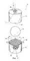
- FIG. 6is a diagrammatical perspective view of another lower mold half constructed according to the invention.
- FIG. 7is a diagrammatical perspective view of yet another lower mold half constructed according to the invention.
- FIG. 8is a diagrammatical cross-sectional view of the mold of FIG. 7 in a closed position.
- a bodywhich is a golf ball core 10 in the preferred embodiment, is placed into a mold 12 .
- the mold 12includes opposing mold portions, defined by two mold halves 14 .
- Each mold half 14defines a corresponding substantially hemispherical cavity 16 and has a mating surface 18 surrounding the hemispherical cavity 16 and facing the opposing mold half 14 .
- the two hemispherical cavities 16together define a substantially spherical mold cavity 20 .
- Inner surfaces 22 of the mold halves 14 , defining the hemispherical cavities 16include a negative dimple pattern with a plurality of protrusions 23 that form dimples in the finished golf ball cover.
- a fixed vent pin 24extends through each mold half 14 to the edge of the mold cavity 20 .
- the diameter of the vent pins 24is slightly smaller than the diameter of the bores 26 which they penetrate, providing a vent 27 defined by a gap of preferably 0.0002 to 0.0005 inches formed between the vent pins 24 and the bores 26 .
- the vent 27thus extends through each mold half 14 to communicate the cavity 20 with the exterior for venting air from the cavity 20 during molding cycles, particularly while the mold 12 is closed.
- Surface 31 of the vent pins 24face the mold cavity 20 and are preferably shaped to form a dimple in a cover molded therein.
- Support pins 28extend through each mold half 14 , into the mold cavity 20 .
- the support pins 28are configured to support the core 10 in a predetermined position within the mold cavity 20 when the core 10 is placed against them.
- the preferred predetermined positionis with the core 10 centered within the mold cavity 20 , to produce a golf ball with a centered core.
- the preferred embodimenthas ten parallel support pins 28 , five in each mold half 14 .
- Other types of support membersmay also be employed in alternative embodiments.
- the mold 12 of the preferred embodimenthas four injection gates 29 configured to receive injection nozzles 30 .
- the gates 29are preferably spaced at equal angles from each other around the mating surfaces 18 . In this case, as there are four gates 29 , they are spaced at about 90° from each other.
- the gates 29communicate the mold cavity 20 to the exterior of the mold 12 , and the nozzles 30 can seat tightly in the gates 29 .
- the nozzles 30can be moved into the gates 29 after the mold halves 14 are pressed together.
- the nozzles 30are configured to inject molten layer material, which in the preferred embodiment is cover material 32 .
- the cover material 32is injected into the mold cavity 20 through the gates 29 at a parting line 34 where the mold halves 14 abut.
- the cover material 32is heated at least to its melting point in a reservoir, and is then forced by a screw through the injection gates 29 , preferably at about 12,000 psi.
- a hot runner systemis preferably employed, where the nozzles 30 are maintained above the melting temperature of the cover material 32 , while the mold is maintained below the melting temperature of the material 32 .
- the flow of the molten cover material 32may be positively stopped after the cavity 20 is filled, and the cover material 32 is maintained in a molten state in runners that lead to the mold cavity 20 .
- the hot runner systemreduces or eliminates any sprues attached to the molded part.
- the cover materialis preferably a material such as engineering type resins, including ionomer resins, such as resins manufactured by Dupont under the trade name SURLYN®, and synthetic balata, a type of polyisoprene which is among the softest of cover materials used in modern golf balls.
- engineering type resinsincluding ionomer resins, such as resins manufactured by Dupont under the trade name SURLYN®, and synthetic balata, a type of polyisoprene which is among the softest of cover materials used in modern golf balls.
- the mold halvesare held together, preferably by a hydraulic press, with a first force.
- this first forceis about 40 kN for a molding machine that includes four individual golf ball molds 12 , although the molding machine preferably includes 4-8 mold cavities.
- FIG. 2shows the core 10 held concentrically within the mold cavity 20 by the support pins 28 .
- the cover material 32is injected in to the mold cavity 20 , the material 32 flows around the core 10 , through a space 36 remaining between the core 10 and the inner surfaces of the mold halves 14 , and air vents from the cavity 20 through vents 27 .
- the injecting of the cover material 32raises the pressure within the mold cavity 20 .
- the mold halves 14are allowed to separate such that the mold is in a partially open position, as shown in FIG. 3.
- a space 38remains between the mold halves 14 in this position.
- This space 38is preferably small enough to prevent the material 32 from flashing through the space 38 , thus keeping the material 32 contained within the mold cavity 20 .
- no extra cover material 32is injected beyond that necessary to fill the mold when it is closed.
- Space 38is preferably between about 0.0015 inches and about 0.0035 inches, and more preferably about 0.0018 inches.
- the space 38allows air, but not material 32 , to vent rapidly from the mold cavity 20 , preventing pressures within the cavity 20 from becoming excessive and from slowing the injection process.
- the pressure within the cavity 20preferably never reaches the magnitude of normal pressures reached in traditional injection molding methods, and thus allows the cover material 32 to flow more quickly.
- FIG. 3also shows cover material fronts 40 as the material 32 fills the space 36 remaining in the cavity 20 . Where these fronts 40 contact each other, they form weld lines. At this stage in the molding process, as in injection molding methods, the cover material 32 is discontinuous across the weld lines.
- Injection of cover material 32is preferably continued from between the mold halves 14 , with the mold 12 partially open.
- the support pins 28are retracted from the core 10 and the cavity 20 , as shown in FIG. 4 .
- the mold halves 14are then compressed towards each other, back to the closed mold position, to compression mold the cover material 32 , which is preferably still substantially in a molten state.
- This compression stepis preferably conducted by pressurizing the hydraulic press to force the mold halves together with a force of about 80 kN.
- this forceis at least about 50% greater than the force biasing the mold halves together during the injection of the material, and more preferably it is about twice the magnitude of the force during the injection of the material 32 .
- the compression molding of the cover material 32relieves a significant portion of the internal stresses therein, including those created at weld lines and by friction with the core 10 and the inner surfaces of the mold halves 14 .
- This compressionfuses the cover material 32 at weld lines and also significantly reduces imperfections in the cover material 32 as a whole and the discontinuities at the weld lines. In processes in which the support pins 28 are retracted after the material 32 has flowed around them, voids remaining where the support pins 28 had once been will be closed by the compression.
- Another advantage provided by the compression stepis the better packing achieved of the material 32 into the features of the mold cavity, compared to simple injection molding. For instance, the material 32 is packed more completely into corners around the protrusions 23 that form the dimples in the finished golf ball cover. This provides an improved finish to the molded product by forming sharper dimple edges.
- the compression stepis commenced once the material 32 has been injected to fill at least about 40% of the cavity 20 . More preferably, the cover material 32 is injected to fill at least about 50%, and most preferably at least about 80% of the cavity 20 before the compression is commenced, requiring little or no further injection of cover material 32 once the mold 12 is closed.
- the mold 12is preferably maintained at a substantially constant temperature of between about 40 and 90° F., most preferably about 50° F. This can be achieved by flowing a fluid such, as cool water, around or through passages within the mold halves 14 . This temperature should be below the freezing point of the cover material 32 . Thus, the material 32 begins to solidify as soon as it is injected. The golf ball can subsequently be removed from the mold 12 with a completed cover around its core 10 .
- FIGS. 6 and 7show a more preferred embodiment of lower mold halves 42 and 44 , each for molding two covers according to the invention.
- the mold halves 42 and 44are configured to mate with corresponding upper mold halves to form the cover around the cores.
- Mold halve 42 of FIG. 6employs a hot-to-cold runner system, in which nozzle 46 is placed against the mold half 42 to inject cover material 32 through internal, hot runner 48 within the mold half 42 to runner 50 in the parting line between the upper and lower mold halves.
- Runner 50feeds ten injection gates 52 surrounding each dimpled half-mold cavity 54 .
- the mold half 44 of FIG. 7uses a cold runner system, in which nozzle 56 injects the cover material 32 directly into a runner system of runners 58 that is disposed completely in the parting line of mold during the molding process. As in mold half 42 , the runners 58 lead into two mold cavities 59 with dimples 23 through gates 52 .
- FIG. 8shows the lower mold half 44 closed against upper mold half 60 at the start of the injection of the cover material 32 through gates 52 into the mold cavity 59 , before moving the mold halves 44 and 60 to the partially open position.
- the finished molded materialis more homogenous than in layers that are purely injection molded around cores, and weld lines are strengthened.
- molded ballsrelease better from the mold halves after the molding is complete than from similar mold halves after a pure injection molding process. Also, the time needed to inject the material is reduced by 15% when molding a golf ball cover around a core, and by 32% when molding a mantle layer around a more internal part of the core. These time reductions are primarily due to the rapid venting achieved by partially opening the mold.
- the adhesion of the molded layer to the body molded aroundis better in runs made according to the invention than in the straight injection molding. Also, better concentricity of the body within the molded layer was achieved. Furthermore, the surface produced had sharper details, improving aesthetic appearance among other things.
- the moldmay be opened by a controlled action of the hydraulic press instead of merely by the pressure produced in the mold cavity by the injected material.
- the initial closing force produced on the mold halvescan be held at about 80 kN, then reduced to about 40 kN to allow the mold 12 to partially open, and then increased again to about 80 kN to compression mold the layer material.
- the mold cavitymay be held open in a fixed position until the start of the compression step. All of these and other modifications are contemplated by the true spirit and scope of the following claims.
Landscapes
- Engineering & Computer Science (AREA)
- Manufacturing & Machinery (AREA)
- Mechanical Engineering (AREA)
- Injection Moulding Of Plastics Or The Like (AREA)
- Moulds For Moulding Plastics Or The Like (AREA)
Abstract
Description
Claims (20)
Priority Applications (4)
| Application Number | Priority Date | Filing Date | Title |
|---|---|---|---|
| US09/213,153US6319451B1 (en) | 1998-12-17 | 1998-12-17 | Method of molding a layer around a body |
| PCT/US1999/029069WO2000035649A1 (en) | 1998-12-17 | 1999-12-07 | Method of molding a layer around a body |
| AU21690/00AAU2169000A (en) | 1998-12-17 | 1999-12-07 | Method of molding a layer around a body |
| JP2000587942AJP3749665B2 (en) | 1998-12-17 | 1999-12-07 | How to mold a layer around the body |
Applications Claiming Priority (1)
| Application Number | Priority Date | Filing Date | Title |
|---|---|---|---|
| US09/213,153US6319451B1 (en) | 1998-12-17 | 1998-12-17 | Method of molding a layer around a body |
Publications (2)
| Publication Number | Publication Date |
|---|---|
| US20010038167A1 US20010038167A1 (en) | 2001-11-08 |
| US6319451B1true US6319451B1 (en) | 2001-11-20 |
Family
ID=22793938
Family Applications (1)
| Application Number | Title | Priority Date | Filing Date |
|---|---|---|---|
| US09/213,153Expired - Fee RelatedUS6319451B1 (en) | 1998-12-17 | 1998-12-17 | Method of molding a layer around a body |
Country Status (4)
| Country | Link |
|---|---|
| US (1) | US6319451B1 (en) |
| JP (1) | JP3749665B2 (en) |
| AU (1) | AU2169000A (en) |
| WO (1) | WO2000035649A1 (en) |
Cited By (128)
| Publication number | Priority date | Publication date | Assignee | Title |
|---|---|---|---|---|
| US20020079615A1 (en)* | 2000-12-22 | 2002-06-27 | Puniello Paul A. | Split vent pin for injection molding |
| US6503436B1 (en)* | 1999-01-11 | 2003-01-07 | Ddk Ltd. | Mold for use in method for producing a harness |
| US20030083152A1 (en)* | 2001-10-18 | 2003-05-01 | Kazushige Sugimoto | Method for manufacturing golf ball |
| US6605243B1 (en)* | 1999-02-23 | 2003-08-12 | Bridgestone Sports Co., Ltd. | Production method of golf ball |
| US20030153402A1 (en)* | 2001-12-04 | 2003-08-14 | Simonds Vincent J. | Molding processes and equipment for forming golf balls with deep dimples |
| US6787091B2 (en) | 2002-10-23 | 2004-09-07 | Acushnet Company | Reaction injection and compression molding of a golf ball |
| US7442194B2 (en) | 2003-11-17 | 2008-10-28 | Covidien Ag | Bipolar forceps having monopolar extension |
| US7458972B2 (en) | 2002-12-10 | 2008-12-02 | Covidien Ag | Electrosurgical electrode having a non-conductive porous ceramic coating |
| US7491201B2 (en) | 2003-05-15 | 2009-02-17 | Covidien Ag | Tissue sealer with non-conductive variable stop members and method of sealing tissue |
| US7491202B2 (en) | 2005-03-31 | 2009-02-17 | Covidien Ag | Electrosurgical forceps with slow closure sealing plates and method of sealing tissue |
| US7500975B2 (en) | 2003-11-19 | 2009-03-10 | Covidien Ag | Spring loaded reciprocating tissue cutting mechanism in a forceps-style electrosurgical instrument |
| US7510556B2 (en) | 1998-10-23 | 2009-03-31 | Coviden Ag | Vessel sealing instrument |
| US7513898B2 (en) | 1998-10-23 | 2009-04-07 | Covidien Ag | Vessel sealing instrument |
| US7540872B2 (en) | 2004-09-21 | 2009-06-02 | Covidien Ag | Articulating bipolar electrosurgical instrument |
| US20090140463A1 (en)* | 2004-06-07 | 2009-06-04 | Puniello Paul A | Golf ball mixing and dispensing process |
| US7553312B2 (en) | 1998-10-23 | 2009-06-30 | Covidien Ag | Vessel sealing instrument |
| US7582087B2 (en) | 1998-10-23 | 2009-09-01 | Covidien Ag | Vessel sealing instrument |
| US7594916B2 (en) | 2005-11-22 | 2009-09-29 | Covidien Ag | Electrosurgical forceps with energy based tissue division |
| US7597693B2 (en) | 2003-06-13 | 2009-10-06 | Covidien Ag | Vessel sealer and divider for use with small trocars and cannulas |
| US7628791B2 (en) | 2005-08-19 | 2009-12-08 | Covidien Ag | Single action tissue sealer |
| US7641653B2 (en) | 2006-05-04 | 2010-01-05 | Covidien Ag | Open vessel sealing forceps disposable handswitch |
| US7655007B2 (en) | 2003-05-01 | 2010-02-02 | Covidien Ag | Method of fusing biomaterials with radiofrequency energy |
| US7661148B2 (en) | 2003-08-21 | 2010-02-16 | Xo Athletic, Co. | Human limb/joint protective pad and method of making |
| US7686804B2 (en) | 2005-01-14 | 2010-03-30 | Covidien Ag | Vessel sealer and divider with rotating sealer and cutter |
| US7686827B2 (en) | 2004-10-21 | 2010-03-30 | Covidien Ag | Magnetic closure mechanism for hemostat |
| US7708735B2 (en) | 2003-05-01 | 2010-05-04 | Covidien Ag | Incorporating rapid cooling in tissue fusion heating processes |
| US7722607B2 (en) | 2005-09-30 | 2010-05-25 | Covidien Ag | In-line vessel sealer and divider |
| US7731717B2 (en) | 2006-08-08 | 2010-06-08 | Covidien Ag | System and method for controlling RF output during tissue sealing |
| US7744615B2 (en) | 2006-07-18 | 2010-06-29 | Covidien Ag | Apparatus and method for transecting tissue on a bipolar vessel sealing instrument |
| US7766910B2 (en) | 2006-01-24 | 2010-08-03 | Tyco Healthcare Group Lp | Vessel sealer and divider for large tissue structures |
| US7771425B2 (en) | 2003-06-13 | 2010-08-10 | Covidien Ag | Vessel sealer and divider having a variable jaw clamping mechanism |
| US7776037B2 (en) | 2006-07-07 | 2010-08-17 | Covidien Ag | System and method for controlling electrode gap during tissue sealing |
| US7776036B2 (en) | 2003-03-13 | 2010-08-17 | Covidien Ag | Bipolar concentric electrode assembly for soft tissue fusion |
| US7789878B2 (en) | 2005-09-30 | 2010-09-07 | Covidien Ag | In-line vessel sealer and divider |
| US20100244318A1 (en)* | 2009-03-31 | 2010-09-30 | Honda Motor Co., Ltd. | Insert molding method and device |
| US7811283B2 (en) | 2003-11-19 | 2010-10-12 | Covidien Ag | Open vessel sealing instrument with hourglass cutting mechanism and over-ratchet safety |
| US7819872B2 (en) | 2005-09-30 | 2010-10-26 | Covidien Ag | Flexible endoscopic catheter with ligasure |
| US7828798B2 (en) | 1997-11-14 | 2010-11-09 | Covidien Ag | Laparoscopic bipolar electrosurgical instrument |
| US7837685B2 (en) | 2005-07-13 | 2010-11-23 | Covidien Ag | Switch mechanisms for safe activation of energy on an electrosurgical instrument |
| US7846158B2 (en) | 2006-05-05 | 2010-12-07 | Covidien Ag | Apparatus and method for electrode thermosurgery |
| US7846161B2 (en) | 2005-09-30 | 2010-12-07 | Covidien Ag | Insulating boot for electrosurgical forceps |
| US7857812B2 (en) | 2003-06-13 | 2010-12-28 | Covidien Ag | Vessel sealer and divider having elongated knife stroke and safety for cutting mechanism |
| US7877852B2 (en) | 2007-09-20 | 2011-02-01 | Tyco Healthcare Group Lp | Method of manufacturing an end effector assembly for sealing tissue |
| US7877853B2 (en) | 2007-09-20 | 2011-02-01 | Tyco Healthcare Group Lp | Method of manufacturing end effector assembly for sealing tissue |
| US7879035B2 (en) | 2005-09-30 | 2011-02-01 | Covidien Ag | Insulating boot for electrosurgical forceps |
| US7887535B2 (en) | 1999-10-18 | 2011-02-15 | Covidien Ag | Vessel sealing wave jaw |
| US7909823B2 (en) | 2005-01-14 | 2011-03-22 | Covidien Ag | Open vessel sealing instrument |
| US20110081437A1 (en)* | 2009-10-05 | 2011-04-07 | Just Add Technology Solutions, Llc | Insulated mold cavity assembly and method for golf ball manufacturing |
| US7922718B2 (en) | 2003-11-19 | 2011-04-12 | Covidien Ag | Open vessel sealing instrument with cutting mechanism |
| US7922953B2 (en) | 2005-09-30 | 2011-04-12 | Covidien Ag | Method for manufacturing an end effector assembly |
| US7931649B2 (en) | 2002-10-04 | 2011-04-26 | Tyco Healthcare Group Lp | Vessel sealing instrument with electrical cutting mechanism |
| US7935052B2 (en) | 2004-09-09 | 2011-05-03 | Covidien Ag | Forceps with spring loaded end effector assembly |
| US7951149B2 (en) | 2006-10-17 | 2011-05-31 | Tyco Healthcare Group Lp | Ablative material for use with tissue treatment device |
| US7955332B2 (en) | 2004-10-08 | 2011-06-07 | Covidien Ag | Mechanism for dividing tissue in a hemostat-style instrument |
| US7963965B2 (en) | 1997-11-12 | 2011-06-21 | Covidien Ag | Bipolar electrosurgical instrument for sealing vessels |
| US8016827B2 (en) | 2008-10-09 | 2011-09-13 | Tyco Healthcare Group Lp | Apparatus, system, and method for performing an electrosurgical procedure |
| USD649249S1 (en) | 2007-02-15 | 2011-11-22 | Tyco Healthcare Group Lp | End effectors of an elongated dissecting and dividing instrument |
| US8070746B2 (en) | 2006-10-03 | 2011-12-06 | Tyco Healthcare Group Lp | Radiofrequency fusion of cardiac tissue |
| US8128624B2 (en) | 2003-05-01 | 2012-03-06 | Covidien Ag | Electrosurgical instrument that directs energy delivery and protects adjacent tissue |
| US8142473B2 (en) | 2008-10-03 | 2012-03-27 | Tyco Healthcare Group Lp | Method of transferring rotational motion in an articulating surgical instrument |
| US8162940B2 (en) | 2002-10-04 | 2012-04-24 | Covidien Ag | Vessel sealing instrument with electrical cutting mechanism |
| US8162973B2 (en) | 2008-08-15 | 2012-04-24 | Tyco Healthcare Group Lp | Method of transferring pressure in an articulating surgical instrument |
| US8192433B2 (en) | 2002-10-04 | 2012-06-05 | Covidien Ag | Vessel sealing instrument with electrical cutting mechanism |
| US8197479B2 (en) | 2008-12-10 | 2012-06-12 | Tyco Healthcare Group Lp | Vessel sealer and divider |
| US20120161363A1 (en)* | 2010-12-23 | 2012-06-28 | Bridgestone Sports Co., Ltd. | Golf ball mold and golf ball manufacturing method |
| US8211105B2 (en) | 1997-11-12 | 2012-07-03 | Covidien Ag | Electrosurgical instrument which reduces collateral damage to adjacent tissue |
| US8221416B2 (en) | 2007-09-28 | 2012-07-17 | Tyco Healthcare Group Lp | Insulating boot for electrosurgical forceps with thermoplastic clevis |
| US8235992B2 (en) | 2007-09-28 | 2012-08-07 | Tyco Healthcare Group Lp | Insulating boot with mechanical reinforcement for electrosurgical forceps |
| US8236025B2 (en) | 2007-09-28 | 2012-08-07 | Tyco Healthcare Group Lp | Silicone insulated electrosurgical forceps |
| US8235993B2 (en) | 2007-09-28 | 2012-08-07 | Tyco Healthcare Group Lp | Insulating boot for electrosurgical forceps with exohinged structure |
| US8241284B2 (en) | 2001-04-06 | 2012-08-14 | Covidien Ag | Vessel sealer and divider with non-conductive stop members |
| US8241283B2 (en) | 2007-09-28 | 2012-08-14 | Tyco Healthcare Group Lp | Dual durometer insulating boot for electrosurgical forceps |
| US8241282B2 (en) | 2006-01-24 | 2012-08-14 | Tyco Healthcare Group Lp | Vessel sealing cutting assemblies |
| US8251996B2 (en) | 2007-09-28 | 2012-08-28 | Tyco Healthcare Group Lp | Insulating sheath for electrosurgical forceps |
| US8257387B2 (en) | 2008-08-15 | 2012-09-04 | Tyco Healthcare Group Lp | Method of transferring pressure in an articulating surgical instrument |
| US8257352B2 (en) | 2003-11-17 | 2012-09-04 | Covidien Ag | Bipolar forceps having monopolar extension |
| US8267935B2 (en) | 2007-04-04 | 2012-09-18 | Tyco Healthcare Group Lp | Electrosurgical instrument reducing current densities at an insulator conductor junction |
| US8267936B2 (en) | 2007-09-28 | 2012-09-18 | Tyco Healthcare Group Lp | Insulating mechanically-interfaced adhesive for electrosurgical forceps |
| US8298232B2 (en) | 2006-01-24 | 2012-10-30 | Tyco Healthcare Group Lp | Endoscopic vessel sealer and divider for large tissue structures |
| US8298228B2 (en) | 1997-11-12 | 2012-10-30 | Coviden Ag | Electrosurgical instrument which reduces collateral damage to adjacent tissue |
| US8303582B2 (en) | 2008-09-15 | 2012-11-06 | Tyco Healthcare Group Lp | Electrosurgical instrument having a coated electrode utilizing an atomic layer deposition technique |
| US8317787B2 (en) | 2008-08-28 | 2012-11-27 | Covidien Lp | Tissue fusion jaw angle improvement |
| US8348948B2 (en) | 2004-03-02 | 2013-01-08 | Covidien Ag | Vessel sealing system using capacitive RF dielectric heating |
| US8361071B2 (en) | 1999-10-22 | 2013-01-29 | Covidien Ag | Vessel sealing forceps with disposable electrodes |
| USD680220S1 (en) | 2012-01-12 | 2013-04-16 | Coviden IP | Slider handle for laparoscopic device |
| US8454602B2 (en) | 2009-05-07 | 2013-06-04 | Covidien Lp | Apparatus, system, and method for performing an electrosurgical procedure |
| US8469957B2 (en) | 2008-10-07 | 2013-06-25 | Covidien Lp | Apparatus, system, and method for performing an electrosurgical procedure |
| US8469956B2 (en) | 2008-07-21 | 2013-06-25 | Covidien Lp | Variable resistor jaw |
| US8486107B2 (en) | 2008-10-20 | 2013-07-16 | Covidien Lp | Method of sealing tissue using radiofrequency energy |
| US8523898B2 (en) | 2009-07-08 | 2013-09-03 | Covidien Lp | Endoscopic electrosurgical jaws with offset knife |
| US8535312B2 (en) | 2008-09-25 | 2013-09-17 | Covidien Lp | Apparatus, system and method for performing an electrosurgical procedure |
| US8540711B2 (en) | 2001-04-06 | 2013-09-24 | Covidien Ag | Vessel sealer and divider |
| US20130256946A1 (en)* | 2012-03-30 | 2013-10-03 | Nike, Inc. | Mold With Midplate And Method Of Molding Golf Ball |
| US8591506B2 (en) | 1998-10-23 | 2013-11-26 | Covidien Ag | Vessel sealing system |
| US8597297B2 (en) | 2006-08-29 | 2013-12-03 | Covidien Ag | Vessel sealing instrument with multiple electrode configurations |
| WO2013181475A1 (en)* | 2012-05-31 | 2013-12-05 | Nike International Ltd | Recyclable golf ball |
| US8623276B2 (en) | 2008-02-15 | 2014-01-07 | Covidien Lp | Method and system for sterilizing an electrosurgical instrument |
| US8636761B2 (en) | 2008-10-09 | 2014-01-28 | Covidien Lp | Apparatus, system, and method for performing an endoscopic electrosurgical procedure |
| US8647341B2 (en) | 2003-06-13 | 2014-02-11 | Covidien Ag | Vessel sealer and divider for use with small trocars and cannulas |
| US20140077414A1 (en)* | 2012-09-18 | 2014-03-20 | Taylor Made Golf Company, Inc. | Golf ball molds and related systems |
| US8734443B2 (en) | 2006-01-24 | 2014-05-27 | Covidien Lp | Vessel sealer and divider for large tissue structures |
| US8764748B2 (en) | 2008-02-06 | 2014-07-01 | Covidien Lp | End effector assembly for electrosurgical device and method for making the same |
| US8784417B2 (en) | 2008-08-28 | 2014-07-22 | Covidien Lp | Tissue fusion jaw angle improvement |
| US8795274B2 (en) | 2008-08-28 | 2014-08-05 | Covidien Lp | Tissue fusion jaw angle improvement |
| US8852228B2 (en) | 2009-01-13 | 2014-10-07 | Covidien Lp | Apparatus, system, and method for performing an electrosurgical procedure |
| US8882766B2 (en) | 2006-01-24 | 2014-11-11 | Covidien Ag | Method and system for controlling delivery of energy to divide tissue |
| US8898888B2 (en) | 2009-09-28 | 2014-12-02 | Covidien Lp | System for manufacturing electrosurgical seal plates |
| US8945125B2 (en) | 2002-11-14 | 2015-02-03 | Covidien Ag | Compressible jaw configuration with bipolar RF output electrodes for soft tissue fusion |
| US8968314B2 (en) | 2008-09-25 | 2015-03-03 | Covidien Lp | Apparatus, system and method for performing an electrosurgical procedure |
| US9023043B2 (en) | 2007-09-28 | 2015-05-05 | Covidien Lp | Insulating mechanically-interfaced boot and jaws for electrosurgical forceps |
| US9028493B2 (en) | 2009-09-18 | 2015-05-12 | Covidien Lp | In vivo attachable and detachable end effector assembly and laparoscopic surgical instrument and methods therefor |
| US9095347B2 (en) | 2003-11-20 | 2015-08-04 | Covidien Ag | Electrically conductive/insulative over shoe for tissue fusion |
| US9107672B2 (en) | 1998-10-23 | 2015-08-18 | Covidien Ag | Vessel sealing forceps with disposable electrodes |
| US9113940B2 (en) | 2011-01-14 | 2015-08-25 | Covidien Lp | Trigger lockout and kickback mechanism for surgical instruments |
| US9375254B2 (en) | 2008-09-25 | 2016-06-28 | Covidien Lp | Seal and separate algorithm |
| US9603652B2 (en) | 2008-08-21 | 2017-03-28 | Covidien Lp | Electrosurgical instrument including a sensor |
| US9848938B2 (en) | 2003-11-13 | 2017-12-26 | Covidien Ag | Compressible jaw configuration with bipolar RF output electrodes for soft tissue fusion |
| US9987078B2 (en) | 2015-07-22 | 2018-06-05 | Covidien Lp | Surgical forceps |
| US10213250B2 (en) | 2015-11-05 | 2019-02-26 | Covidien Lp | Deployment and safety mechanisms for surgical instruments |
| US10231777B2 (en) | 2014-08-26 | 2019-03-19 | Covidien Lp | Methods of manufacturing jaw members of an end-effector assembly for a surgical instrument |
| US10646267B2 (en) | 2013-08-07 | 2020-05-12 | Covidien LLP | Surgical forceps |
| US10710287B2 (en) | 2014-10-17 | 2020-07-14 | Taiwan Green Point Enterprises Co., Ltd. | Injection molding method and mold mechanism |
| US10835309B1 (en) | 2002-06-25 | 2020-11-17 | Covidien Ag | Vessel sealer and divider |
| US10856933B2 (en) | 2016-08-02 | 2020-12-08 | Covidien Lp | Surgical instrument housing incorporating a channel and methods of manufacturing the same |
| US10918407B2 (en) | 2016-11-08 | 2021-02-16 | Covidien Lp | Surgical instrument for grasping, treating, and/or dividing tissue |
| US10987159B2 (en) | 2015-08-26 | 2021-04-27 | Covidien Lp | Electrosurgical end effector assemblies and electrosurgical forceps configured to reduce thermal spread |
| US11166759B2 (en) | 2017-05-16 | 2021-11-09 | Covidien Lp | Surgical forceps |
| USD956973S1 (en) | 2003-06-13 | 2022-07-05 | Covidien Ag | Movable handle for endoscopic vessel sealer and divider |
Families Citing this family (8)
| Publication number | Priority date | Publication date | Assignee | Title |
|---|---|---|---|---|
| US7402271B2 (en)* | 2004-12-01 | 2008-07-22 | Acushnet Company | Castable liquid rubber compositions for golf balls |
| US20070031532A1 (en)* | 2005-08-05 | 2007-02-08 | Fa-Shen Chen | Adjustment structure for mold cavity capacity |
| US9101800B2 (en) | 2011-07-08 | 2015-08-11 | Rawlings Sporting Goods Company, Inc. | Molded game ball |
| CN102689379B (en)* | 2011-03-25 | 2014-03-26 | 台慧(厦门)运动器材有限公司 | Baseball and softball manufacturing method and ball coat manufacturing mold thereof |
| CN102553182A (en)* | 2012-02-13 | 2012-07-11 | 台慧(厦门)运动器材有限公司 | Baseball and softball processing method |
| ES2980274T3 (en)* | 2017-06-06 | 2024-09-30 | West Pharmaceutical Services Inc | Manufacturing process for elastomer articles with built-in electronics |
| US10675838B2 (en)* | 2017-11-29 | 2020-06-09 | Fourté International, Sdn. Bhd | Molding processes for metallic foams, apparatuses, and products |
| US12151415B1 (en)* | 2021-05-07 | 2024-11-26 | Acushnet Company | Hot to cold runner system for golf ball injection mold and methods of using same |
Citations (12)
| Publication number | Priority date | Publication date | Assignee | Title |
|---|---|---|---|---|
| US3016574A (en) | 1958-08-06 | 1962-01-16 | Colgate Palmolive Co | Casting apparatus |
| US3068522A (en)* | 1960-07-19 | 1962-12-18 | David L Nickerson | Method and apparatus for molding covers on spherical bodies |
| US3177280A (en)* | 1960-05-23 | 1965-04-06 | Dunlop Rubber Co | Process for the manufacture of polyurethane coated balls |
| US3787159A (en)* | 1969-08-21 | 1974-01-22 | Eckert & Ziegler Gmbh | Apparatus for injection molding with thermosetting resins |
| US4501715A (en) | 1983-05-18 | 1985-02-26 | Gilbert Barfield | Mold and method for forming golf balls |
| US5059364A (en)* | 1988-03-24 | 1991-10-22 | Kabushiki Kaisha Komatsu Seisakusha | Injection-compression molding machine and method of molding by using the machine |
| US5147657A (en) | 1989-10-31 | 1992-09-15 | John Giza | Retractable pin for an injection mold |
| US5221509A (en)* | 1988-10-27 | 1993-06-22 | Kabushiki Kaisha Komatsu Seisakusho | Method and apparatus for injection and compression molding |
| US5415817A (en) | 1993-10-22 | 1995-05-16 | Industrial Technology Research Institute | Process for molding plastic lenses |
| US5424017A (en)* | 1993-04-12 | 1995-06-13 | Hinduja; Murli L. | Method for forming fiber-reinforced articles |
| US5798071A (en)* | 1995-06-07 | 1998-08-25 | Acushnet Company | Method for the combined injection and compression molding of golf balls |
| US5945047A (en)* | 1997-03-13 | 1999-08-31 | The Japan Steel Works, Ltd. | Method of injection-compression molding |
- 1998
- 1998-12-17USUS09/213,153patent/US6319451B1/ennot_activeExpired - Fee Related
- 1999
- 1999-12-07AUAU21690/00Apatent/AU2169000A/ennot_activeAbandoned
- 1999-12-07WOPCT/US1999/029069patent/WO2000035649A1/enactiveApplication Filing
- 1999-12-07JPJP2000587942Apatent/JP3749665B2/ennot_activeExpired - Fee Related
Patent Citations (12)
| Publication number | Priority date | Publication date | Assignee | Title |
|---|---|---|---|---|
| US3016574A (en) | 1958-08-06 | 1962-01-16 | Colgate Palmolive Co | Casting apparatus |
| US3177280A (en)* | 1960-05-23 | 1965-04-06 | Dunlop Rubber Co | Process for the manufacture of polyurethane coated balls |
| US3068522A (en)* | 1960-07-19 | 1962-12-18 | David L Nickerson | Method and apparatus for molding covers on spherical bodies |
| US3787159A (en)* | 1969-08-21 | 1974-01-22 | Eckert & Ziegler Gmbh | Apparatus for injection molding with thermosetting resins |
| US4501715A (en) | 1983-05-18 | 1985-02-26 | Gilbert Barfield | Mold and method for forming golf balls |
| US5059364A (en)* | 1988-03-24 | 1991-10-22 | Kabushiki Kaisha Komatsu Seisakusha | Injection-compression molding machine and method of molding by using the machine |
| US5221509A (en)* | 1988-10-27 | 1993-06-22 | Kabushiki Kaisha Komatsu Seisakusho | Method and apparatus for injection and compression molding |
| US5147657A (en) | 1989-10-31 | 1992-09-15 | John Giza | Retractable pin for an injection mold |
| US5424017A (en)* | 1993-04-12 | 1995-06-13 | Hinduja; Murli L. | Method for forming fiber-reinforced articles |
| US5415817A (en) | 1993-10-22 | 1995-05-16 | Industrial Technology Research Institute | Process for molding plastic lenses |
| US5798071A (en)* | 1995-06-07 | 1998-08-25 | Acushnet Company | Method for the combined injection and compression molding of golf balls |
| US5945047A (en)* | 1997-03-13 | 1999-08-31 | The Japan Steel Works, Ltd. | Method of injection-compression molding |
Non-Patent Citations (1)
| Title |
|---|
| "Coining" in Injection Molding Handbook, 2nd ed. pp. 1005-1006, 1995.* |
Cited By (224)
| Publication number | Priority date | Publication date | Assignee | Title |
|---|---|---|---|---|
| US8298228B2 (en) | 1997-11-12 | 2012-10-30 | Coviden Ag | Electrosurgical instrument which reduces collateral damage to adjacent tissue |
| US7963965B2 (en) | 1997-11-12 | 2011-06-21 | Covidien Ag | Bipolar electrosurgical instrument for sealing vessels |
| US8211105B2 (en) | 1997-11-12 | 2012-07-03 | Covidien Ag | Electrosurgical instrument which reduces collateral damage to adjacent tissue |
| US7828798B2 (en) | 1997-11-14 | 2010-11-09 | Covidien Ag | Laparoscopic bipolar electrosurgical instrument |
| US9375271B2 (en) | 1998-10-23 | 2016-06-28 | Covidien Ag | Vessel sealing system |
| US7896878B2 (en) | 1998-10-23 | 2011-03-01 | Coviden Ag | Vessel sealing instrument |
| US7553312B2 (en) | 1998-10-23 | 2009-06-30 | Covidien Ag | Vessel sealing instrument |
| US9107672B2 (en) | 1998-10-23 | 2015-08-18 | Covidien Ag | Vessel sealing forceps with disposable electrodes |
| US7513898B2 (en) | 1998-10-23 | 2009-04-07 | Covidien Ag | Vessel sealing instrument |
| US7510556B2 (en) | 1998-10-23 | 2009-03-31 | Coviden Ag | Vessel sealing instrument |
| US7887536B2 (en) | 1998-10-23 | 2011-02-15 | Covidien Ag | Vessel sealing instrument |
| US8591506B2 (en) | 1998-10-23 | 2013-11-26 | Covidien Ag | Vessel sealing system |
| US7582087B2 (en) | 1998-10-23 | 2009-09-01 | Covidien Ag | Vessel sealing instrument |
| US9375270B2 (en) | 1998-10-23 | 2016-06-28 | Covidien Ag | Vessel sealing system |
| US9463067B2 (en) | 1998-10-23 | 2016-10-11 | Covidien Ag | Vessel sealing system |
| US7947041B2 (en) | 1998-10-23 | 2011-05-24 | Covidien Ag | Vessel sealing instrument |
| US6503436B1 (en)* | 1999-01-11 | 2003-01-07 | Ddk Ltd. | Mold for use in method for producing a harness |
| US6605243B1 (en)* | 1999-02-23 | 2003-08-12 | Bridgestone Sports Co., Ltd. | Production method of golf ball |
| US7887535B2 (en) | 1999-10-18 | 2011-02-15 | Covidien Ag | Vessel sealing wave jaw |
| US8361071B2 (en) | 1999-10-22 | 2013-01-29 | Covidien Ag | Vessel sealing forceps with disposable electrodes |
| US20020079615A1 (en)* | 2000-12-22 | 2002-06-27 | Puniello Paul A. | Split vent pin for injection molding |
| US7341687B2 (en) | 2000-12-22 | 2008-03-11 | Acushnet Company | Method of forming a golf ball |
| US20050173832A1 (en)* | 2000-12-22 | 2005-08-11 | Acushnet Company | Split vent pin for injection molding |
| US6877974B2 (en)* | 2000-12-22 | 2005-04-12 | Acushnet Company | Split vent pin for injection molding |
| US10265121B2 (en) | 2001-04-06 | 2019-04-23 | Covidien Ag | Vessel sealer and divider |
| US8540711B2 (en) | 2001-04-06 | 2013-09-24 | Covidien Ag | Vessel sealer and divider |
| US10251696B2 (en) | 2001-04-06 | 2019-04-09 | Covidien Ag | Vessel sealer and divider with stop members |
| US10568682B2 (en) | 2001-04-06 | 2020-02-25 | Covidien Ag | Vessel sealer and divider |
| US10849681B2 (en) | 2001-04-06 | 2020-12-01 | Covidien Ag | Vessel sealer and divider |
| US9861430B2 (en) | 2001-04-06 | 2018-01-09 | Covidien Ag | Vessel sealer and divider |
| US10687887B2 (en) | 2001-04-06 | 2020-06-23 | Covidien Ag | Vessel sealer and divider |
| US10881453B1 (en) | 2001-04-06 | 2021-01-05 | Covidien Ag | Vessel sealer and divider |
| US9737357B2 (en) | 2001-04-06 | 2017-08-22 | Covidien Ag | Vessel sealer and divider |
| US8241284B2 (en) | 2001-04-06 | 2012-08-14 | Covidien Ag | Vessel sealer and divider with non-conductive stop members |
| US6838036B2 (en)* | 2001-10-18 | 2005-01-04 | Sumitomo Rubber Industries, Ltd. | Method for manufacturing golf ball |
| US20030083152A1 (en)* | 2001-10-18 | 2003-05-01 | Kazushige Sugimoto | Method for manufacturing golf ball |
| US6817853B2 (en)* | 2001-12-04 | 2004-11-16 | Callaway Golf Company | Molding processes and equipment for forming golf balls with deep dimples |
| US20050006815A1 (en)* | 2001-12-04 | 2005-01-13 | Callaway Golf Company | Molding processes and equipment for forming golf balls with deep dimples |
| US20030153402A1 (en)* | 2001-12-04 | 2003-08-14 | Simonds Vincent J. | Molding processes and equipment for forming golf balls with deep dimples |
| US10918436B2 (en) | 2002-06-25 | 2021-02-16 | Covidien Ag | Vessel sealer and divider |
| US10835309B1 (en) | 2002-06-25 | 2020-11-17 | Covidien Ag | Vessel sealer and divider |
| US8333765B2 (en) | 2002-10-04 | 2012-12-18 | Covidien Ag | Vessel sealing instrument with electrical cutting mechanism |
| US8162940B2 (en) | 2002-10-04 | 2012-04-24 | Covidien Ag | Vessel sealing instrument with electrical cutting mechanism |
| US9585716B2 (en) | 2002-10-04 | 2017-03-07 | Covidien Ag | Vessel sealing instrument with electrical cutting mechanism |
| US8192433B2 (en) | 2002-10-04 | 2012-06-05 | Covidien Ag | Vessel sealing instrument with electrical cutting mechanism |
| US8740901B2 (en) | 2002-10-04 | 2014-06-03 | Covidien Ag | Vessel sealing instrument with electrical cutting mechanism |
| US10537384B2 (en) | 2002-10-04 | 2020-01-21 | Covidien Lp | Vessel sealing instrument with electrical cutting mechanism |
| US8551091B2 (en) | 2002-10-04 | 2013-10-08 | Covidien Ag | Vessel sealing instrument with electrical cutting mechanism |
| US7931649B2 (en) | 2002-10-04 | 2011-04-26 | Tyco Healthcare Group Lp | Vessel sealing instrument with electrical cutting mechanism |
| US10987160B2 (en) | 2002-10-04 | 2021-04-27 | Covidien Ag | Vessel sealing instrument with cutting mechanism |
| US6787091B2 (en) | 2002-10-23 | 2004-09-07 | Acushnet Company | Reaction injection and compression molding of a golf ball |
| US8945125B2 (en) | 2002-11-14 | 2015-02-03 | Covidien Ag | Compressible jaw configuration with bipolar RF output electrodes for soft tissue fusion |
| US7458972B2 (en) | 2002-12-10 | 2008-12-02 | Covidien Ag | Electrosurgical electrode having a non-conductive porous ceramic coating |
| US7776036B2 (en) | 2003-03-13 | 2010-08-17 | Covidien Ag | Bipolar concentric electrode assembly for soft tissue fusion |
| US8128624B2 (en) | 2003-05-01 | 2012-03-06 | Covidien Ag | Electrosurgical instrument that directs energy delivery and protects adjacent tissue |
| US7753909B2 (en) | 2003-05-01 | 2010-07-13 | Covidien Ag | Electrosurgical instrument which reduces thermal damage to adjacent tissue |
| US7655007B2 (en) | 2003-05-01 | 2010-02-02 | Covidien Ag | Method of fusing biomaterials with radiofrequency energy |
| US9149323B2 (en) | 2003-05-01 | 2015-10-06 | Covidien Ag | Method of fusing biomaterials with radiofrequency energy |
| US7708735B2 (en) | 2003-05-01 | 2010-05-04 | Covidien Ag | Incorporating rapid cooling in tissue fusion heating processes |
| US8679114B2 (en) | 2003-05-01 | 2014-03-25 | Covidien Ag | Incorporating rapid cooling in tissue fusion heating processes |
| USRE47375E1 (en) | 2003-05-15 | 2019-05-07 | Coviden Ag | Tissue sealer with non-conductive variable stop members and method of sealing tissue |
| US8496656B2 (en) | 2003-05-15 | 2013-07-30 | Covidien Ag | Tissue sealer with non-conductive variable stop members and method of sealing tissue |
| US7491201B2 (en) | 2003-05-15 | 2009-02-17 | Covidien Ag | Tissue sealer with non-conductive variable stop members and method of sealing tissue |
| USD956973S1 (en) | 2003-06-13 | 2022-07-05 | Covidien Ag | Movable handle for endoscopic vessel sealer and divider |
| US8647341B2 (en) | 2003-06-13 | 2014-02-11 | Covidien Ag | Vessel sealer and divider for use with small trocars and cannulas |
| US10918435B2 (en) | 2003-06-13 | 2021-02-16 | Covidien Ag | Vessel sealer and divider |
| US7597693B2 (en) | 2003-06-13 | 2009-10-06 | Covidien Ag | Vessel sealer and divider for use with small trocars and cannulas |
| US7771425B2 (en) | 2003-06-13 | 2010-08-10 | Covidien Ag | Vessel sealer and divider having a variable jaw clamping mechanism |
| US10278772B2 (en) | 2003-06-13 | 2019-05-07 | Covidien Ag | Vessel sealer and divider |
| US10842553B2 (en) | 2003-06-13 | 2020-11-24 | Covidien Ag | Vessel sealer and divider |
| US7857812B2 (en) | 2003-06-13 | 2010-12-28 | Covidien Ag | Vessel sealer and divider having elongated knife stroke and safety for cutting mechanism |
| US9492225B2 (en) | 2003-06-13 | 2016-11-15 | Covidien Ag | Vessel sealer and divider for use with small trocars and cannulas |
| US20100100995A1 (en)* | 2003-08-21 | 2010-04-29 | Xo Athletic, Co. | Human limb/joint protective pad and method of making |
| US7661148B2 (en) | 2003-08-21 | 2010-02-16 | Xo Athletic, Co. | Human limb/joint protective pad and method of making |
| US8353062B2 (en) | 2003-08-21 | 2013-01-15 | Xo Athletic, Co. | Human limb/joint protective pad and method of making |
| US9848938B2 (en) | 2003-11-13 | 2017-12-26 | Covidien Ag | Compressible jaw configuration with bipolar RF output electrodes for soft tissue fusion |
| US7445621B2 (en) | 2003-11-17 | 2008-11-04 | Covidien Ag | Bipolar forceps having monopolar extension |
| US8257352B2 (en) | 2003-11-17 | 2012-09-04 | Covidien Ag | Bipolar forceps having monopolar extension |
| US7481810B2 (en) | 2003-11-17 | 2009-01-27 | Covidien Ag | Bipolar forceps having monopolar extension |
| US10441350B2 (en) | 2003-11-17 | 2019-10-15 | Covidien Ag | Bipolar forceps having monopolar extension |
| US7442194B2 (en) | 2003-11-17 | 2008-10-28 | Covidien Ag | Bipolar forceps having monopolar extension |
| US8597296B2 (en) | 2003-11-17 | 2013-12-03 | Covidien Ag | Bipolar forceps having monopolar extension |
| US8394096B2 (en) | 2003-11-19 | 2013-03-12 | Covidien Ag | Open vessel sealing instrument with cutting mechanism |
| US7500975B2 (en) | 2003-11-19 | 2009-03-10 | Covidien Ag | Spring loaded reciprocating tissue cutting mechanism in a forceps-style electrosurgical instrument |
| US7811283B2 (en) | 2003-11-19 | 2010-10-12 | Covidien Ag | Open vessel sealing instrument with hourglass cutting mechanism and over-ratchet safety |
| US8303586B2 (en) | 2003-11-19 | 2012-11-06 | Covidien Ag | Spring loaded reciprocating tissue cutting mechanism in a forceps-style electrosurgical instrument |
| US8623017B2 (en) | 2003-11-19 | 2014-01-07 | Covidien Ag | Open vessel sealing instrument with hourglass cutting mechanism and overratchet safety |
| US7922718B2 (en) | 2003-11-19 | 2011-04-12 | Covidien Ag | Open vessel sealing instrument with cutting mechanism |
| US9980770B2 (en) | 2003-11-20 | 2018-05-29 | Covidien Ag | Electrically conductive/insulative over-shoe for tissue fusion |
| US9095347B2 (en) | 2003-11-20 | 2015-08-04 | Covidien Ag | Electrically conductive/insulative over shoe for tissue fusion |
| US8348948B2 (en) | 2004-03-02 | 2013-01-08 | Covidien Ag | Vessel sealing system using capacitive RF dielectric heating |
| US7655171B2 (en)* | 2004-06-07 | 2010-02-02 | Acushnet Company | Golf ball mixing and dispensing process |
| US20090140463A1 (en)* | 2004-06-07 | 2009-06-04 | Puniello Paul A | Golf ball mixing and dispensing process |
| US7935052B2 (en) | 2004-09-09 | 2011-05-03 | Covidien Ag | Forceps with spring loaded end effector assembly |
| US8366709B2 (en) | 2004-09-21 | 2013-02-05 | Covidien Ag | Articulating bipolar electrosurgical instrument |
| US7799028B2 (en) | 2004-09-21 | 2010-09-21 | Covidien Ag | Articulating bipolar electrosurgical instrument |
| US7540872B2 (en) | 2004-09-21 | 2009-06-02 | Covidien Ag | Articulating bipolar electrosurgical instrument |
| US7955332B2 (en) | 2004-10-08 | 2011-06-07 | Covidien Ag | Mechanism for dividing tissue in a hemostat-style instrument |
| US8123743B2 (en) | 2004-10-08 | 2012-02-28 | Covidien Ag | Mechanism for dividing tissue in a hemostat-style instrument |
| US7686827B2 (en) | 2004-10-21 | 2010-03-30 | Covidien Ag | Magnetic closure mechanism for hemostat |
| US8147489B2 (en) | 2005-01-14 | 2012-04-03 | Covidien Ag | Open vessel sealing instrument |
| US7951150B2 (en) | 2005-01-14 | 2011-05-31 | Covidien Ag | Vessel sealer and divider with rotating sealer and cutter |
| US7686804B2 (en) | 2005-01-14 | 2010-03-30 | Covidien Ag | Vessel sealer and divider with rotating sealer and cutter |
| US7909823B2 (en) | 2005-01-14 | 2011-03-22 | Covidien Ag | Open vessel sealing instrument |
| US8382754B2 (en) | 2005-03-31 | 2013-02-26 | Covidien Ag | Electrosurgical forceps with slow closure sealing plates and method of sealing tissue |
| US7491202B2 (en) | 2005-03-31 | 2009-02-17 | Covidien Ag | Electrosurgical forceps with slow closure sealing plates and method of sealing tissue |
| US7837685B2 (en) | 2005-07-13 | 2010-11-23 | Covidien Ag | Switch mechanisms for safe activation of energy on an electrosurgical instrument |
| US8945127B2 (en) | 2005-08-19 | 2015-02-03 | Covidien Ag | Single action tissue sealer |
| US8277447B2 (en) | 2005-08-19 | 2012-10-02 | Covidien Ag | Single action tissue sealer |
| US8945126B2 (en) | 2005-08-19 | 2015-02-03 | Covidien Ag | Single action tissue sealer |
| US9198717B2 (en) | 2005-08-19 | 2015-12-01 | Covidien Ag | Single action tissue sealer |
| US10188452B2 (en) | 2005-08-19 | 2019-01-29 | Covidien Ag | Single action tissue sealer |
| US7628791B2 (en) | 2005-08-19 | 2009-12-08 | Covidien Ag | Single action tissue sealer |
| US8939973B2 (en) | 2005-08-19 | 2015-01-27 | Covidien Ag | Single action tissue sealer |
| US8394095B2 (en) | 2005-09-30 | 2013-03-12 | Covidien Ag | Insulating boot for electrosurgical forceps |
| US7722607B2 (en) | 2005-09-30 | 2010-05-25 | Covidien Ag | In-line vessel sealer and divider |
| US8668689B2 (en) | 2005-09-30 | 2014-03-11 | Covidien Ag | In-line vessel sealer and divider |
| US9579145B2 (en) | 2005-09-30 | 2017-02-28 | Covidien Ag | Flexible endoscopic catheter with ligasure |
| US9549775B2 (en) | 2005-09-30 | 2017-01-24 | Covidien Ag | In-line vessel sealer and divider |
| US8197633B2 (en) | 2005-09-30 | 2012-06-12 | Covidien Ag | Method for manufacturing an end effector assembly |
| US7922953B2 (en) | 2005-09-30 | 2011-04-12 | Covidien Ag | Method for manufacturing an end effector assembly |
| US8641713B2 (en) | 2005-09-30 | 2014-02-04 | Covidien Ag | Flexible endoscopic catheter with ligasure |
| US7879035B2 (en) | 2005-09-30 | 2011-02-01 | Covidien Ag | Insulating boot for electrosurgical forceps |
| US7846161B2 (en) | 2005-09-30 | 2010-12-07 | Covidien Ag | Insulating boot for electrosurgical forceps |
| US7819872B2 (en) | 2005-09-30 | 2010-10-26 | Covidien Ag | Flexible endoscopic catheter with ligasure |
| US8361072B2 (en) | 2005-09-30 | 2013-01-29 | Covidien Ag | Insulating boot for electrosurgical forceps |
| US7789878B2 (en) | 2005-09-30 | 2010-09-07 | Covidien Ag | In-line vessel sealer and divider |
| USRE44834E1 (en) | 2005-09-30 | 2014-04-08 | Covidien Ag | Insulating boot for electrosurgical forceps |
| US7594916B2 (en) | 2005-11-22 | 2009-09-29 | Covidien Ag | Electrosurgical forceps with energy based tissue division |
| US8241282B2 (en) | 2006-01-24 | 2012-08-14 | Tyco Healthcare Group Lp | Vessel sealing cutting assemblies |
| US7766910B2 (en) | 2006-01-24 | 2010-08-03 | Tyco Healthcare Group Lp | Vessel sealer and divider for large tissue structures |
| US8298232B2 (en) | 2006-01-24 | 2012-10-30 | Tyco Healthcare Group Lp | Endoscopic vessel sealer and divider for large tissue structures |
| US9539053B2 (en) | 2006-01-24 | 2017-01-10 | Covidien Lp | Vessel sealer and divider for large tissue structures |
| US9918782B2 (en) | 2006-01-24 | 2018-03-20 | Covidien Lp | Endoscopic vessel sealer and divider for large tissue structures |
| US9113903B2 (en) | 2006-01-24 | 2015-08-25 | Covidien Lp | Endoscopic vessel sealer and divider for large tissue structures |
| US8882766B2 (en) | 2006-01-24 | 2014-11-11 | Covidien Ag | Method and system for controlling delivery of energy to divide tissue |
| US8734443B2 (en) | 2006-01-24 | 2014-05-27 | Covidien Lp | Vessel sealer and divider for large tissue structures |
| US7641653B2 (en) | 2006-05-04 | 2010-01-05 | Covidien Ag | Open vessel sealing forceps disposable handswitch |
| US7846158B2 (en) | 2006-05-05 | 2010-12-07 | Covidien Ag | Apparatus and method for electrode thermosurgery |
| US8034052B2 (en) | 2006-05-05 | 2011-10-11 | Covidien Ag | Apparatus and method for electrode thermosurgery |
| US7776037B2 (en) | 2006-07-07 | 2010-08-17 | Covidien Ag | System and method for controlling electrode gap during tissue sealing |
| US7744615B2 (en) | 2006-07-18 | 2010-06-29 | Covidien Ag | Apparatus and method for transecting tissue on a bipolar vessel sealing instrument |
| US7731717B2 (en) | 2006-08-08 | 2010-06-08 | Covidien Ag | System and method for controlling RF output during tissue sealing |
| US8597297B2 (en) | 2006-08-29 | 2013-12-03 | Covidien Ag | Vessel sealing instrument with multiple electrode configurations |
| US8425504B2 (en) | 2006-10-03 | 2013-04-23 | Covidien Lp | Radiofrequency fusion of cardiac tissue |
| US8070746B2 (en) | 2006-10-03 | 2011-12-06 | Tyco Healthcare Group Lp | Radiofrequency fusion of cardiac tissue |
| US7951149B2 (en) | 2006-10-17 | 2011-05-31 | Tyco Healthcare Group Lp | Ablative material for use with tissue treatment device |
| USD649249S1 (en) | 2007-02-15 | 2011-11-22 | Tyco Healthcare Group Lp | End effectors of an elongated dissecting and dividing instrument |
| US8267935B2 (en) | 2007-04-04 | 2012-09-18 | Tyco Healthcare Group Lp | Electrosurgical instrument reducing current densities at an insulator conductor junction |
| US7877853B2 (en) | 2007-09-20 | 2011-02-01 | Tyco Healthcare Group Lp | Method of manufacturing end effector assembly for sealing tissue |
| US7877852B2 (en) | 2007-09-20 | 2011-02-01 | Tyco Healthcare Group Lp | Method of manufacturing an end effector assembly for sealing tissue |
| US8236025B2 (en) | 2007-09-28 | 2012-08-07 | Tyco Healthcare Group Lp | Silicone insulated electrosurgical forceps |
| US8696667B2 (en) | 2007-09-28 | 2014-04-15 | Covidien Lp | Dual durometer insulating boot for electrosurgical forceps |
| US8241283B2 (en) | 2007-09-28 | 2012-08-14 | Tyco Healthcare Group Lp | Dual durometer insulating boot for electrosurgical forceps |
| US8235993B2 (en) | 2007-09-28 | 2012-08-07 | Tyco Healthcare Group Lp | Insulating boot for electrosurgical forceps with exohinged structure |
| US9554841B2 (en) | 2007-09-28 | 2017-01-31 | Covidien Lp | Dual durometer insulating boot for electrosurgical forceps |
| US9023043B2 (en) | 2007-09-28 | 2015-05-05 | Covidien Lp | Insulating mechanically-interfaced boot and jaws for electrosurgical forceps |
| US8221416B2 (en) | 2007-09-28 | 2012-07-17 | Tyco Healthcare Group Lp | Insulating boot for electrosurgical forceps with thermoplastic clevis |
| US8267936B2 (en) | 2007-09-28 | 2012-09-18 | Tyco Healthcare Group Lp | Insulating mechanically-interfaced adhesive for electrosurgical forceps |
| US8235992B2 (en) | 2007-09-28 | 2012-08-07 | Tyco Healthcare Group Lp | Insulating boot with mechanical reinforcement for electrosurgical forceps |
| US8251996B2 (en) | 2007-09-28 | 2012-08-28 | Tyco Healthcare Group Lp | Insulating sheath for electrosurgical forceps |
| US8764748B2 (en) | 2008-02-06 | 2014-07-01 | Covidien Lp | End effector assembly for electrosurgical device and method for making the same |
| US8623276B2 (en) | 2008-02-15 | 2014-01-07 | Covidien Lp | Method and system for sterilizing an electrosurgical instrument |
| US9113905B2 (en) | 2008-07-21 | 2015-08-25 | Covidien Lp | Variable resistor jaw |
| US8469956B2 (en) | 2008-07-21 | 2013-06-25 | Covidien Lp | Variable resistor jaw |
| US9247988B2 (en) | 2008-07-21 | 2016-02-02 | Covidien Lp | Variable resistor jaw |
| US8257387B2 (en) | 2008-08-15 | 2012-09-04 | Tyco Healthcare Group Lp | Method of transferring pressure in an articulating surgical instrument |
| US8162973B2 (en) | 2008-08-15 | 2012-04-24 | Tyco Healthcare Group Lp | Method of transferring pressure in an articulating surgical instrument |
| US9603652B2 (en) | 2008-08-21 | 2017-03-28 | Covidien Lp | Electrosurgical instrument including a sensor |
| US8784417B2 (en) | 2008-08-28 | 2014-07-22 | Covidien Lp | Tissue fusion jaw angle improvement |
| US8317787B2 (en) | 2008-08-28 | 2012-11-27 | Covidien Lp | Tissue fusion jaw angle improvement |
| US8795274B2 (en) | 2008-08-28 | 2014-08-05 | Covidien Lp | Tissue fusion jaw angle improvement |
| US8303582B2 (en) | 2008-09-15 | 2012-11-06 | Tyco Healthcare Group Lp | Electrosurgical instrument having a coated electrode utilizing an atomic layer deposition technique |
| US9375254B2 (en) | 2008-09-25 | 2016-06-28 | Covidien Lp | Seal and separate algorithm |
| US8535312B2 (en) | 2008-09-25 | 2013-09-17 | Covidien Lp | Apparatus, system and method for performing an electrosurgical procedure |
| US8968314B2 (en) | 2008-09-25 | 2015-03-03 | Covidien Lp | Apparatus, system and method for performing an electrosurgical procedure |
| US8568444B2 (en) | 2008-10-03 | 2013-10-29 | Covidien Lp | Method of transferring rotational motion in an articulating surgical instrument |
| US8142473B2 (en) | 2008-10-03 | 2012-03-27 | Tyco Healthcare Group Lp | Method of transferring rotational motion in an articulating surgical instrument |
| US8469957B2 (en) | 2008-10-07 | 2013-06-25 | Covidien Lp | Apparatus, system, and method for performing an electrosurgical procedure |
| US9113898B2 (en) | 2008-10-09 | 2015-08-25 | Covidien Lp | Apparatus, system, and method for performing an electrosurgical procedure |
| US8016827B2 (en) | 2008-10-09 | 2011-09-13 | Tyco Healthcare Group Lp | Apparatus, system, and method for performing an electrosurgical procedure |
| US8636761B2 (en) | 2008-10-09 | 2014-01-28 | Covidien Lp | Apparatus, system, and method for performing an endoscopic electrosurgical procedure |
| US8486107B2 (en) | 2008-10-20 | 2013-07-16 | Covidien Lp | Method of sealing tissue using radiofrequency energy |
| US8197479B2 (en) | 2008-12-10 | 2012-06-12 | Tyco Healthcare Group Lp | Vessel sealer and divider |
| US8852228B2 (en) | 2009-01-13 | 2014-10-07 | Covidien Lp | Apparatus, system, and method for performing an electrosurgical procedure |
| US9655674B2 (en) | 2009-01-13 | 2017-05-23 | Covidien Lp | Apparatus, system and method for performing an electrosurgical procedure |
| US20100244318A1 (en)* | 2009-03-31 | 2010-09-30 | Honda Motor Co., Ltd. | Insert molding method and device |
| US9345535B2 (en) | 2009-05-07 | 2016-05-24 | Covidien Lp | Apparatus, system and method for performing an electrosurgical procedure |
| US8454602B2 (en) | 2009-05-07 | 2013-06-04 | Covidien Lp | Apparatus, system, and method for performing an electrosurgical procedure |
| US10085794B2 (en) | 2009-05-07 | 2018-10-02 | Covidien Lp | Apparatus, system and method for performing an electrosurgical procedure |
| US8858554B2 (en) | 2009-05-07 | 2014-10-14 | Covidien Lp | Apparatus, system, and method for performing an electrosurgical procedure |
| US8523898B2 (en) | 2009-07-08 | 2013-09-03 | Covidien Lp | Endoscopic electrosurgical jaws with offset knife |
| US9028493B2 (en) | 2009-09-18 | 2015-05-12 | Covidien Lp | In vivo attachable and detachable end effector assembly and laparoscopic surgical instrument and methods therefor |
| US9931131B2 (en) | 2009-09-18 | 2018-04-03 | Covidien Lp | In vivo attachable and detachable end effector assembly and laparoscopic surgical instrument and methods therefor |
| US11490955B2 (en) | 2009-09-28 | 2022-11-08 | Covidien Lp | Electrosurgical seal plates |
| US9265552B2 (en) | 2009-09-28 | 2016-02-23 | Covidien Lp | Method of manufacturing electrosurgical seal plates |
| US10188454B2 (en) | 2009-09-28 | 2019-01-29 | Covidien Lp | System for manufacturing electrosurgical seal plates |
| US11026741B2 (en) | 2009-09-28 | 2021-06-08 | Covidien Lp | Electrosurgical seal plates |
| US9750561B2 (en) | 2009-09-28 | 2017-09-05 | Covidien Lp | System for manufacturing electrosurgical seal plates |
| US8898888B2 (en) | 2009-09-28 | 2014-12-02 | Covidien Lp | System for manufacturing electrosurgical seal plates |
| US8882490B2 (en)* | 2009-10-05 | 2014-11-11 | Just Add Technology Solutions Llc | Insulated mold cavity assembly and method for golf ball manufacturing |
| US20110081437A1 (en)* | 2009-10-05 | 2011-04-07 | Just Add Technology Solutions, Llc | Insulated mold cavity assembly and method for golf ball manufacturing |
| US8408891B2 (en)* | 2010-12-23 | 2013-04-02 | Bridgestone Sports Co., Ltd | Golf ball mold and golf ball manufacturing method |
| US9108347B2 (en) | 2010-12-23 | 2015-08-18 | Bridgestone Sports Co., Ltd. | Golf ball mold and golf ball manufacturing method |
| US20120161363A1 (en)* | 2010-12-23 | 2012-06-28 | Bridgestone Sports Co., Ltd. | Golf ball mold and golf ball manufacturing method |
| US9113940B2 (en) | 2011-01-14 | 2015-08-25 | Covidien Lp | Trigger lockout and kickback mechanism for surgical instruments |
| US11660108B2 (en) | 2011-01-14 | 2023-05-30 | Covidien Lp | Trigger lockout and kickback mechanism for surgical instruments |
| US10383649B2 (en) | 2011-01-14 | 2019-08-20 | Covidien Lp | Trigger lockout and kickback mechanism for surgical instruments |
| USD680220S1 (en) | 2012-01-12 | 2013-04-16 | Coviden IP | Slider handle for laparoscopic device |
| US9211662B2 (en)* | 2012-03-30 | 2015-12-15 | Nike, Inc. | Mold with midplate and method of molding golf ball |
| US20130256946A1 (en)* | 2012-03-30 | 2013-10-03 | Nike, Inc. | Mold With Midplate And Method Of Molding Golf Ball |
| WO2013181475A1 (en)* | 2012-05-31 | 2013-12-05 | Nike International Ltd | Recyclable golf ball |
| US20140077414A1 (en)* | 2012-09-18 | 2014-03-20 | Taylor Made Golf Company, Inc. | Golf ball molds and related systems |
| US9409362B2 (en)* | 2012-09-18 | 2016-08-09 | Taylor Made Golf Company, Inc. | Golf ball molds and related systems |
| US10646267B2 (en) | 2013-08-07 | 2020-05-12 | Covidien LLP | Surgical forceps |
| US10231777B2 (en) | 2014-08-26 | 2019-03-19 | Covidien Lp | Methods of manufacturing jaw members of an end-effector assembly for a surgical instrument |
| US10710287B2 (en) | 2014-10-17 | 2020-07-14 | Taiwan Green Point Enterprises Co., Ltd. | Injection molding method and mold mechanism |
| US9987078B2 (en) | 2015-07-22 | 2018-06-05 | Covidien Lp | Surgical forceps |
| US11382686B2 (en) | 2015-07-22 | 2022-07-12 | Covidien Lp | Surgical forceps |
| US10987159B2 (en) | 2015-08-26 | 2021-04-27 | Covidien Lp | Electrosurgical end effector assemblies and electrosurgical forceps configured to reduce thermal spread |
| US10213250B2 (en) | 2015-11-05 | 2019-02-26 | Covidien Lp | Deployment and safety mechanisms for surgical instruments |
| US10856933B2 (en) | 2016-08-02 | 2020-12-08 | Covidien Lp | Surgical instrument housing incorporating a channel and methods of manufacturing the same |
| US10918407B2 (en) | 2016-11-08 | 2021-02-16 | Covidien Lp | Surgical instrument for grasping, treating, and/or dividing tissue |
| US11166759B2 (en) | 2017-05-16 | 2021-11-09 | Covidien Lp | Surgical forceps |
Also Published As
| Publication number | Publication date |
|---|---|
| US20010038167A1 (en) | 2001-11-08 |
| WO2000035649A1 (en) | 2000-06-22 |
| JP2002532280A (en) | 2002-10-02 |
| AU2169000A (en) | 2000-07-03 |
| JP3749665B2 (en) | 2006-03-01 |
Similar Documents
| Publication | Publication Date | Title |
|---|---|---|
| US6319451B1 (en) | Method of molding a layer around a body | |
| US5112556A (en) | Golf ball apparatus and method for manufacture | |
| US5201523A (en) | Molded seamless golf ball | |
| US6787091B2 (en) | Reaction injection and compression molding of a golf ball | |
| US5798071A (en) | Method for the combined injection and compression molding of golf balls | |
| AU647781B2 (en) | Golf ball injection mold | |
| US6235230B1 (en) | Ring gate for retractable pin injection molding | |
| JP2711796B2 (en) | How to make a new-like golf ball using a recovered golf ball | |
| US6817852B2 (en) | Direct cavity gate golf ball injection mold | |
| JPH09313647A (en) | Mold for injection molding of golf ball and method for manufacturing golf ball using the mold | |
| JP3743457B2 (en) | Golf ball injection molding method and golf ball injection mold | |
| US20010048180A1 (en) | Golf ball mold cavity with subgates | |
| JPH03178415A (en) | Retracting type pin mold and its retracting type pin | |
| JPH06297501A (en) | Molding method and die for hollow article | |
| JPH07110523B2 (en) | Multilayer sphere manufacturing apparatus and manufacturing method | |
| US6893362B2 (en) | Mold and method of molding golf ball having dimples on the equator | |
| JP2973869B2 (en) | Golf ball manufacturing method and golf ball manufacturing mold | |
| JP2000271972A (en) | Production of golf ball and injection mold therefor | |
| JP3582179B2 (en) | Method for producing injection molded article having hollow shape | |
| KR101973630B1 (en) | Resin molding manufacturing method using the resin backflow gas injection | |
| JPH05200786A (en) | Manifold device for hot runner mold | |
| JP2722370B2 (en) | Molding method and molding die for synthetic resin products | |
| JPH0136767B2 (en) | ||
| CA2063366C (en) | Golf ball injection mold | |
| CN113510901A (en) | Product mold and injection molding method using same |
Legal Events
| Date | Code | Title | Description |
|---|---|---|---|
| AS | Assignment | Owner name:ACUSHNET COMPANY, MASSACHUSETTS Free format text:ASSIGNMENT OF ASSIGNORS INTEREST;ASSIGNOR:BRUNE, GARY J.;REEL/FRAME:009660/0140 Effective date:19981216 | |
| FEPP | Fee payment procedure | Free format text:PAYOR NUMBER ASSIGNED (ORIGINAL EVENT CODE: ASPN); ENTITY STATUS OF PATENT OWNER: LARGE ENTITY | |
| FPAY | Fee payment | Year of fee payment:4 | |
| FPAY | Fee payment | Year of fee payment:8 | |
| AS | Assignment | Owner name:KOREA DEVELOPMENT BANK, NEW YORK BRANCH, NEW YORK Free format text:SECURITY AGREEMENT;ASSIGNOR:ACUSHNET COMPANY;REEL/FRAME:027346/0075 Effective date:20111031 | |
| REMI | Maintenance fee reminder mailed | ||
| LAPS | Lapse for failure to pay maintenance fees | ||
| STCH | Information on status: patent discontinuation | Free format text:PATENT EXPIRED DUE TO NONPAYMENT OF MAINTENANCE FEES UNDER 37 CFR 1.362 | |
| FP | Lapsed due to failure to pay maintenance fee | Effective date:20131120 | |
| AS | Assignment | Owner name:ACUSHNET COMPANY, MASSACHUSETTS Free format text:RELEASE OF SECURITY INTEREST IN PATENTS PREVIOUSLY RECORDED AT REEL/FRAME (027346/0075);ASSIGNOR:KOREA DEVELOPMENT BANK, NEW YORK BRANCH;REEL/FRAME:039939/0098 Effective date:20160728 |