US6319227B1 - Automatic/manual longitudinal position translator and rotary drive system for catheters - Google Patents
Automatic/manual longitudinal position translator and rotary drive system for cathetersDownload PDFInfo
- Publication number
- US6319227B1 US6319227B1US09/130,198US13019898AUS6319227B1US 6319227 B1US6319227 B1US 6319227B1US 13019898 AUS13019898 AUS 13019898AUS 6319227 B1US6319227 B1US 6319227B1
- Authority
- US
- United States
- Prior art keywords
- drive
- connectors
- assembly
- combined
- rotary
- Prior art date
- Legal status (The legal status is an assumption and is not a legal conclusion. Google has not performed a legal analysis and makes no representation as to the accuracy of the status listed.)
- Expired - Lifetime
Links
Images


Classifications
- A—HUMAN NECESSITIES
- A61—MEDICAL OR VETERINARY SCIENCE; HYGIENE
- A61B—DIAGNOSIS; SURGERY; IDENTIFICATION
- A61B8/00—Diagnosis using ultrasonic, sonic or infrasonic waves
- A61B8/12—Diagnosis using ultrasonic, sonic or infrasonic waves in body cavities or body tracts, e.g. by using catheters
- A—HUMAN NECESSITIES
- A61—MEDICAL OR VETERINARY SCIENCE; HYGIENE
- A61B—DIAGNOSIS; SURGERY; IDENTIFICATION
- A61B8/00—Diagnosis using ultrasonic, sonic or infrasonic waves
- A61B8/44—Constructional features of the ultrasonic, sonic or infrasonic diagnostic device
- A61B8/4444—Constructional features of the ultrasonic, sonic or infrasonic diagnostic device related to the probe
- A61B8/4461—Features of the scanning mechanism, e.g. for moving the transducer within the housing of the probe
Definitions
- the present inventionrelates generally to catheters systems.
- the present inventionis directed to a catheter system that provides for the controlled longitudinal movement of an elongate element—such as a rotatable imaging core with an ultrasonic transducer or an optical fiber imaging device at its distal end, or a drive cable with an atherectomy cutter at its distal end-housed within a sheath positioned within a patient.
- an elongate elementsuch as a rotatable imaging core with an ultrasonic transducer or an optical fiber imaging device at its distal end, or a drive cable with an atherectomy cutter at its distal end-housed within a sheath positioned within a patient.
- Arteriosclerosisalso known as atherosclerosis, is a common human ailment arising from the deposition of fatty-like substances, referred to as atheromas or plaque, on the walls of blood vessels. Such deposits occur in both peripheral blood vessels which feed the limbs of the body and the coronary vessels which feed the heart. When the deposits accumulate in localized regions of a blood vessel, stenosis, or narrowing of the vascular channel, occurs. Blood flow is restricted and the person's health is at serious risk.
- Generally depositsextend some longitudinal distance along the length of a vessel.
- a physiciantypically moves a handle attached to a proximal end of the imaging catheter along the vessel, for example, by pushing or pulling the catheter.
- Imaging using computer-assisted reconstruction algorithmsenables physicians to view a representation of the patient's interior intravascular structures in two or three dimensions (i.e., so-called three-dimensional or longitudinal view reconstruction).
- image reconstruction algorithmstypically employ data-averaging techniques which assume that the intravascular structure between an adjacent pair of data samples will simply be an average of each such data sample.
- the algorithmsuse graphical “fill in” techniques to depict a selected section of a patient's vascular system under investigation.
- lesions and/or other vessel abnormalitiesmay in fact remain undetected (i.e., since they might lie between a pair of data samples and thereby be “masked” by the image reconstruction algorithms mentioned previously).
- U.S. Pat. No. 5,485,486discloses an ultrasound imaging transducer which is capable of being translated longitudinally within a section of a patient's vascular system at a precise constant rate through the use of a longitudinal translation assembly.
- the longitudinal translation assemblymoves the entire rotary drive assembly to provide the desired longitudinal movement of the transducer.
- Such an assemblycan be operated in a “hands-off” manner which allows the physician to devote his or her attention entirely to the real-time images with the assurance that all sections of the vessel are displayed.
- a longitudinal translation assemblycan work well, it is relatively large, bulky and heavy; it is expensive; and it is cumbersome to set up, in part because the rotary drive and longitudinal translation assemblies are wrapped in separate sterile drapes (plastic bags) for sterility.
- the catheter assemblyis mounted to a draped pullback assembly for use, used and then discarded after use.
- the catheter assemblyincludes the electronics necessary to send, receive and filter signals. These electronic components are disposed of with the rest of the catheter assembly which raises the cost of the procedure.
- the present inventionprovides an automatic pullback catheter system in which costly electronic signal processing components can be removed from the disposable catheter assembly and incorporated into the drive assembly. This helps reduce the cost of each use.
- the catheter assemblyneed only include the sheath, the elongate operative element within the sheath, the drive connector, and the data/information connector, typically a coaxial electrical connector.
- the drive and data/information connectorsare preferably combined into a combined connector. The resulting structure is compact, simple to use, and reduces the cost of the disposable catheter assembly.
- the drive assemblyincludes a body to which a drive chassis is mounted for movement along a longitudinal path by a longitudinal driver.
- the longitudinal drivertypically includes a motor which rotates a longitudinal drive screw selectively coupled to the drive chassis by a threaded clamp or clutch.
- the drive assemblyalso includes a rotary driver mounted to the drive chassis and movable with the drive chassis along the longitudinal path.
- the rotary driverincludes a rotary drive motor and a first combined connector rotatable by the rotary drive motor.
- the catheter assemblyincludes a hollow sheath housing an elongate operative element, typically a rotatable imaging core or cable having an imaging element at its distal end.
- the sheathincludes a proximal portion removably mounted to the body.
- the catheter assemblyalso includes a rotatable and axially movable second combined connector connected to the proximal end of the cable or other operative element.
- the second combined connectoris preferably housed within the proximal portion of the sheath.
- the first and second combined connectorsare preferably blind matable connectors to facilitate mounting the catheter assembly to and dismounting the catheter assembly from the drive assembly.
- the combined connectorsprovide for the transfer of information/data from the operative element to the drive assembly as well as for both the longitudinal movement coupling of the two combined connectors and the rotary movement coupling of the two combined connectors. Therefore, rotating the first combined connector by the rotary drive motor mounted to the drive chassis rotates the second combined connector thereby rotating the elongate operative element.
- actuating the longitudinal driverdrives the drive chassis along the longitudinal path which causes the longitudinal movement of the operative element within the sheath.
- the drive chassisis preferably mounted to the body along a linear bearing.
- a linear bearinghelps to ensure that the longitudinal movement of the drive chassis is smooth, encounters little friction and is very stable.
- Using a manually actuated threaded clamp to selectively secure the drive chassis to the longitudinal drive screwpermits the user to decouple the drive chassis from the longitudinal drive shaft when desired and manually move the drive chassis, and thus the imaging element at the distal end of the imaging core, to the desired longitudinal position.
- connection between the first and second combined connectorsis a blind matable connection. That is, the connectors need only be properly aligned so pushing the two connectors together causes them to properly mate.
- the data/information connectionis made using coaxial plug and socket connectors which not only provide the desired electrical, optical or other type of connection, but also provides sufficient frictional engagement between the first and second combined connectors to permit the longitudinal movement of the elongate operative element (e.g. cable) within the sheath. While the frictional engagement between the two data/information connectors may be enough to provide an acceptable rotary drive interface, it is preferred that the first and second combined connectors include first and second rotary drive connectors including rotary drive surfaces. These rotary drive surfaces are preferably arranged to guide the two connectors into proper rotary alignment when engaged.
- the proximal portion of the cableis preferably much stiffer than the remainder of the cable. This helps to ensure a fluid-tight seal can be provided between the cable and the proximal portion of the sheath. This is important when a fluid or flush port is provided distally of such seal; the seal helps to prevent the fluid from entering into the drive assembly.
- this stiff, proximal portioncan be made sufficiently long so that when the rotary driver is in the longitudinally pulled-back or proximal position, only the stiff proximal portion of the cable is exterior of the sheath and inside the drive assembly.
- the stiff portion of the cableis stiff enough to be self-supporting and does not droop within the drive assembly. Pushing the cable distally is also facilitated by the use of a cable with a stiff proximal portion.
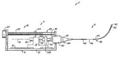
- FIG. 1is a simplified schematic view of a catheter system made according to the invention
- FIG. 2is a perspective view of a prototype of the drive assembly and the proximal portion of the catheter assembly of FIG. 1 with the drive assembly in a distal, extended position and with the sides of the body of the drive assembly removed for convenient access;
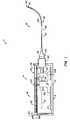
- FIG. 2Ais similar to FIG. 2 with the drive assembly in a proximal, pulled-back or retracted position;
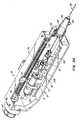
- FIG. 3is a partial cross-sectional view of the catheter assembly of FIGS. 1 and 2 with the cable assembly in a distal position, the bellows collapsed and the imaging element at the tip of the sheath;
- FIG. 3Ais a view similar to FIG. 3 with the cable assembly in the proximal position of FIG. 2A, the bellows expanded and the imaging element pulled back away from the tip of the sheath;
- FIG. 4is an isometric view of the cable assembly of FIG. 3;
- FIG. 5is an exploded isometric view of the cable assembly of FIG. 4;
- FIG. 6is an isometric view of the first combined connector and bearing assembly of FIG. 1;
- FIG. 7is an exploded isometric view of the first combined connector and bearing assembly of FIG. 6 .
- FIG. 1illustrates, in schematic form, a catheter system 2 including a drive assembly 4 to which a typically disposable catheter assembly 6 is removably mounted.
- drive assembly 4includes a body 8 having a base 10 supporting a linear bearing track 12 .
- a drive chassis 14is mounted for linear movement along a longitudinal path 16 by a longitudinal driver 18 .
- Longitudinal driver 18includes a longitudinal drive motor 20 which rotates a longitudinal drive screw 22 rotatably supported at each end by body 8 .
- Driver 18also includes a threaded clamp 24 having threads which match the threads on drive screw 22 .
- Clamp 24is mounted to and moves with drive chassis 14 .
- Clamp 24is normally biased into engagement with drive screw 22 , but can be moved out of engagement with drive shaft 22 by the user moving a drive clamp handle 26 ; doing so disengages clamp 24 from drive screw 22 and permits the user to move drive chassis 14 along longitudinal path 16 .
- Releasing drive clamp handle 26allows clamp 24 to again engage drive screw 22 ; this secures drive chassis 14 in position along longitudinal path 16 , subject to any subsequent rotation of drive screw 22 .
- Drive assembly 4also includes a rotary driver 28 mounted to and carried by drive chassis 14 .
- Rotary driver 28includes a rotary drive motor 30 , mounted to drive chassis 14 , which rotates a drive shaft 32 .
- drive shaft 32rotates a first combined connector 34 .
- First combined connector 34moves with drive chassis 14 along longitudinal path 16 .
- First combined connector 34operably engages a second combined connector 36 , also discussed below, the second combined connector being a part of catheter assembly 6 .
- Catheter assembly 6includes a hollow sheath 38 extending between a tip 40 at its distal end and a hub 42 at its proximal end with a main portion 43 in between.
- Sheath 38houses a cable assembly 44 , see FIGS. 4 and 5.
- Cable assembly 44includes second combined connector 36 from which a cable 46 (the elongate operative element) extends.
- Cable 46includes a stiff initial section 48 extending from second combined connector 36 and an image element 50 at the distal end of cable 46 .
- Stiff initial section 48is typically made by securing a length of hypotube (a thin-walled stainless steel tube) over the proximal end of the cable.
- Cable assembly 44can be used for ultrasonic imaging, laser imaging or other imaging purposes. Also, cable assembly 44 could be used for purposes other than imaging such as ablation, photodynamic therapy, delivery of therapeutic or diagnostic fluids, delivery of devices such as stents, and for other purposes.
- tip 40is open to permit fluid to be flushed through the interior of sheath 44 ; in some situations tip 40 may be sealed. In some cases image element 50 may be positioned past tip 40 and external of sheath 38 .
- Second combined connector 36includes a second rotary drive connector 52 and a second electrical connector or plug 54 (a data/information connector).
- a drive joint 56has three spring fingers 58 which engage recesses 60 formed in drive connector 52 to secure plug 54 in place.
- Plug 54has spring finger electrical contacts 62 surrounding a center pin 64 .
- Initial section 48 of cable 46is secured to the interior of a rotary shaft coupler 66 , coupler 66 being affixed to a hub portion 68 of drive joint 56 .
- Appropriate electrical connections between drive cable 46 and plug 54are made in a conventional manner.
- Hub 42 of sheath 38includes a main cavity 70 which houses second combined connector 36 .
- Catheter assembly 6also includes a bearing washer 74 mounted between second combined connector 36 and the proximal end of main cavity 70 .
- Bellows 78typically made of polyester shrink or PTFE, is fastened at its proximal edge 80 to drive joint 56 and its distal edge 82 to hub 42 . Bellows 78 is used to help prevent contamination of the interior of sheath 38 .
- Bearing washer 74used to secure the distal end of a bellows 78 to hub 42 , is made of a low friction polymer.
- Hub 42also includes a fluid or flush port 84 coupled to the interior of sheath 38 to permit the sheath interior to be flushed with a saline solution or other suitable fluid.
- An O-ring fluid seal 86is used between hub 42 and coupler 66 (in position of FIG. 2) or stiff initial section 48 (in position of FIG. 2A) to prevent the flow of fluid from flush port 84 back into cavity 70 and thus into the interior of drive assembly 4 .
- Catheter assembly 6is quickly and easily mounted to drive assembly 4 .
- the proximal end of hub 42is inserted into a through-hole 88 formed in a proximal portion mount 90 of body 8 of drive assembly 4 until latched into place. This occurs by the engagement of an upwardly-extending, spring-biased latch pin, not shown, engaging a recess 94 formed in hub 42 ; the latch pin can be removed from recess 94 by the user pressing on a release button 92 .
- Mounting catheter assembly 6 to drive assembly 4preferably occurs when rotary driver 28 is in the distal-most or fully-extended position of FIGS. 1 and 2.
- second combined connector 36automatically blind matably connects with first combined connector 34 to provide for longitudinal and rotational driving connection and for electrical connection.
- First combined connector assembly 34includes a first rotary drive connector 96 configured for complementary mating engagement with second rotary drive connector 52 .
- Assembly 34also includes a first electrical connector or socket 98 secured between connector 96 and a second drive joint 100 .
- Socket 98 and plug 54are configured to mate with one another in a coaxial mating arrangement in a manner similar to connector 22 , electrical connector 54 and drive joint 56 of FIG. 5 .
- First combined connector 34is coupled to a bearing assembly 102 .
- Bearing assembly 102includes first and second housing portions 104 , 106 which house drive shaft 32 .
- Electrical wires 107extend from socket 98 , through housing portion 104 , and through a cut-out 109 in housing portion 106 for connection to appropriate circuitry, not shown.
- Bearing assembly 102is supported by the front end 108 of drive chassis 14 engaging housing portion 104 .
- Drive shaft 32is supported within housing portions 104 , 106 by a pair of bearings 110 , 112 .
- Drive shaft 32passes freely through a non-rotating ferrite 114 which is fixed within distal housing portion 104 , typically through a light press fit or through the use of an adhesive.
- Non-rotating ferrite 114is positioned at a necked down portion 116 of drive shaft 108 .
- a rotating ferrite 118is mounted to drive shaft 32 to be positioned adjacent to non-rotating ferrite 114 .
- Rotating ferrite 118is secured to drive shaft 32 , such as through a light press fit, and rotates with the drive shaft.
- Rotating and non-rotating ferrites 118 , 114are used to monitor the rotation of drive shaft 32 and, thus, of cable assembly 44 .
- the hub portion 120 of drive joint 100is housed within the distal end of distal housing portion 104 .
- the distal end 122 of drive shaft 32is keyed or otherwise fixed to hub portion 120 so that rotating drive shaft 32 causes first rotary drive connector 96 to rotate, thus rotating cable assembly 44 .
- the proximal end 124 of drive shaft 32extends beyond housing portion 106 and into driven engagement with rotary drive motor 30 .
- rotary motion of rotary drive motor 30causes drive shaft 32 to rotate, thus rotating cable assembly 44 .
- Longitudinal movement of drive chassis 14 through the engagement of clamp 24 with drive screw 22causes rotary driver 28 to move along longitudinal path 16 .
- the frictional connection between plug 54 and socket 98causes cable assembly 44 , see FIG. 4, to be pulled along longitudinal path 16 with the longitudinal movement of rotary driver 28 .
- the use of stiffened section 48 as the initial portion of cable 46provides the necessary support for the cable during this longitudinal movement.
- an appropriate catheter assembly 6is selected to be used during a procedure. If rotary driver 28 is not in its distal-most position of FIGS. 1 and 2, the user will place rotary driver 28 at its distal-most position, typically by grasping drive clamp handle 26 , temporarily disengaging clamp 24 from drive screw 22 , and then manually moving the rotary driver in the distal direction to its distal-most position. Once in position, drive clamp handle 26 is released, permitting the reengagement of threaded clamp 24 with drive screw 22 , thus securing rotary driver 28 in place. Spring biased release button 92 is then depressed and the proximal end of hub 42 is inserted into through-hole 88 formed in proximal portion mount 90 .
- hub 42Once hub 42 is partially inserted, release button 92 is released and hub 42 is continued to be inserted into mount 90 until the locking pin attached to release button 92 engages recess 94 formed in hub 42 . When this occurs, hub 42 becomes properly secured to drive assembly 4 .
- first and second combined connectors 34 , 36blind matably connect to one another.
- First and second rotary drive connectors 96 , 52have alignment/drive surfaces 126 , 128 which extend both circumferentially and longitudinally so to provide the proper rotary orientation upon engagement of the connectors.
- plug 54 and socket 98are axially aligned during this movement and become electrically coupled to one another as the first and second rotary drive connectors 96 , 52 mate.
- Tip 40 of catheter assembly 6is then transluminally positioned to the target area within the patient.
- rotary driver 28With rotary driver 28 in its distal-most position, which causes imaging element 50 to be in its distal-most position, rotary drive motor 30 and longitudinal drive motor 20 can be simultaneously or sequentially actuated to permit 360° images to be obtained along a length of vessel or other cavity within a patient. Excessive proximal movement is prevented when drive chassis 14 engages a limit switch 130 mounted to body 8 .
- imaging element 50The movements of imaging element 50 are controlled in a very stable manner through the use of motors 20 , 30 to provide superior imaging than could otherwise be obtained.
- rotary driver 28can be manually longitudinally positioned through the disengagement of clamp 24 , the manual movement of rotary actuator 28 along longitudinal path 16 and the reengagement of clamp 24 with drive screw 22 .
- the length of longitudinal travelwill be about 10 cm.
- Drive assembly 4can be made to accommodate other lengths of longitudinal travel as well.
- Alignment/drive surfaces 126 , 128are basically dual V-shaped surfaces so that cable assembly 44 ends up at one of two different rotary orientations, 180° apart, relative to the rotary orientation of first combined connector 34 .
- Body 8is shown in a very simple form. In a commercial embodiment, body 8 would preferably have a more ergonomic shape, and may have fixed or extendable legs to allow drive assembly to rest comfortably but securely on, for example, the patient's leg or chest. While it is expected that drive assembly 4 will be connected to remote power and control assemblies, it may be desirable to include a controller, input panel, and a battery pack as a part of drive assembly 4 to make the drive assembly substantially self-contained.
- Data from catheter system 2could be then provided to an external recorder and/or monitor through hardwire or telemetry, such as by using radio frequency transmitters and receivers. While the invention is particularly adapted for imaging of vascular regions, the invention is suitable types of diagnostic and therapeutic procedures in vascular and other body structures.
- bellows 78other structures, such as telescoping tubing, can be used to help prevent contamination of the interior of sheath 38 ; the bellows or tubing could have round, rectangular or other cross-sectioned shapes.
Landscapes
- Life Sciences & Earth Sciences (AREA)
- Health & Medical Sciences (AREA)
- Biomedical Technology (AREA)
- Biophysics (AREA)
- Nuclear Medicine, Radiotherapy & Molecular Imaging (AREA)
- Pathology (AREA)
- Radiology & Medical Imaging (AREA)
- Engineering & Computer Science (AREA)
- Physics & Mathematics (AREA)
- Heart & Thoracic Surgery (AREA)
- Medical Informatics (AREA)
- Molecular Biology (AREA)
- Surgery (AREA)
- Animal Behavior & Ethology (AREA)
- General Health & Medical Sciences (AREA)
- Public Health (AREA)
- Veterinary Medicine (AREA)
- Ultra Sonic Daignosis Equipment (AREA)
- Surgical Instruments (AREA)
Abstract
Description
Claims (22)
Priority Applications (10)
| Application Number | Priority Date | Filing Date | Title |
|---|---|---|---|
| US09/130,198US6319227B1 (en) | 1998-08-05 | 1998-08-05 | Automatic/manual longitudinal position translator and rotary drive system for catheters |
| EP99933068AEP1100376B1 (en) | 1998-08-05 | 1999-07-30 | Automatic/manual longitudinal position translator and rotary drive system for catheters |
| PCT/IB1999/001363WO2000007500A1 (en) | 1998-08-05 | 1999-07-30 | Automatic/manual longitudinal position translator and rotary drive system for catheters |
| CA002339491ACA2339491A1 (en) | 1998-08-05 | 1999-07-30 | Automatic/manual longitudinal position translator and rotary drive system for catheters |
| JP2000563188AJP4637355B2 (en) | 1998-08-05 | 1999-07-30 | Automatic / manual longitudinal position transducer and rotary drive system for catheters |
| ES99933068TES2251206T3 (en) | 1998-08-05 | 1999-07-30 | AUTOMATIC / MANUAL LONGITUDINAL POSITION TRANSFER DEVICE AND ROTARY PROPULSION SYSTEM FOR CATHETERS. |
| DE69927980TDE69927980T2 (en) | 1998-08-05 | 1999-07-30 | AUTOMATIC / MANUAL LENGTH POSITION ADJUSTMENT AND TURN DRIVE SYSTEM FOR CATHETERS |
| US09/970,314US6814727B2 (en) | 1998-08-05 | 2001-10-02 | Automatic/manual longitudinal position translator and rotary drive system for catheters |
| US10/956,783US7613493B2 (en) | 1998-08-05 | 2004-10-01 | Automatic/manual longitudinal position translator and rotary drive system for catheters |
| JP2008258989AJP5430902B2 (en) | 1998-08-05 | 2008-10-03 | Automatic / manual longitudinal position transducer for catheter and rotary drive system |
Applications Claiming Priority (1)
| Application Number | Priority Date | Filing Date | Title |
|---|---|---|---|
| US09/130,198US6319227B1 (en) | 1998-08-05 | 1998-08-05 | Automatic/manual longitudinal position translator and rotary drive system for catheters |
Related Child Applications (1)
| Application Number | Title | Priority Date | Filing Date |
|---|---|---|---|
| US09/970,314ContinuationUS6814727B2 (en) | 1998-08-05 | 2001-10-02 | Automatic/manual longitudinal position translator and rotary drive system for catheters |
Publications (1)
| Publication Number | Publication Date |
|---|---|
| US6319227B1true US6319227B1 (en) | 2001-11-20 |
Family
ID=22443521
Family Applications (3)
| Application Number | Title | Priority Date | Filing Date |
|---|---|---|---|
| US09/130,198Expired - LifetimeUS6319227B1 (en) | 1998-08-05 | 1998-08-05 | Automatic/manual longitudinal position translator and rotary drive system for catheters |
| US09/970,314Expired - LifetimeUS6814727B2 (en) | 1998-08-05 | 2001-10-02 | Automatic/manual longitudinal position translator and rotary drive system for catheters |
| US10/956,783Expired - Fee RelatedUS7613493B2 (en) | 1998-08-05 | 2004-10-01 | Automatic/manual longitudinal position translator and rotary drive system for catheters |
Family Applications After (2)
| Application Number | Title | Priority Date | Filing Date |
|---|---|---|---|
| US09/970,314Expired - LifetimeUS6814727B2 (en) | 1998-08-05 | 2001-10-02 | Automatic/manual longitudinal position translator and rotary drive system for catheters |
| US10/956,783Expired - Fee RelatedUS7613493B2 (en) | 1998-08-05 | 2004-10-01 | Automatic/manual longitudinal position translator and rotary drive system for catheters |
Country Status (7)
| Country | Link |
|---|---|
| US (3) | US6319227B1 (en) |
| EP (1) | EP1100376B1 (en) |
| JP (2) | JP4637355B2 (en) |
| CA (1) | CA2339491A1 (en) |
| DE (1) | DE69927980T2 (en) |
| ES (1) | ES2251206T3 (en) |
| WO (1) | WO2000007500A1 (en) |
Cited By (69)
| Publication number | Priority date | Publication date | Assignee | Title |
|---|---|---|---|---|
| US6485482B1 (en)* | 1999-07-30 | 2002-11-26 | Scimed Life Systems, Inc. | Rotational and translational drive coupling for catheter assembly |
| US20020183723A1 (en)* | 1998-10-06 | 2002-12-05 | Scimed Life Systems, Inc. | Driveable catheter system |
| US20030187369A1 (en)* | 2002-03-28 | 2003-10-02 | Lewis Stephen B. | Optical pullback sensor for measuring linear displacement of a catheter or other elongate member |
| US6783524B2 (en)* | 2001-04-19 | 2004-08-31 | Intuitive Surgical, Inc. | Robotic surgical tool with ultrasound cauterizing and cutting instrument |
| US6827693B2 (en)* | 1998-09-08 | 2004-12-07 | Scimed Life Systems, Inc. | System and method for intraluminal imaging |
| US20050043618A1 (en)* | 1998-08-05 | 2005-02-24 | Scimed Life Systems, Inc. | Automatic/manual longitudinal position translator and rotary drive system for catheters |
| US20050216033A1 (en)* | 2001-02-15 | 2005-09-29 | Endo Via Medical Inc. | Robotically controlled medical instrument with a flexible section |
| US20060041245A1 (en)* | 2001-05-06 | 2006-02-23 | Ferry Steven J | Systems and methods for medical device a dvancement and rotation |
| US20060107612A1 (en)* | 2004-10-01 | 2006-05-25 | Pelc Robert J | Anchoring device |
| WO2006135551A2 (en) | 2005-06-08 | 2006-12-21 | Xtent, Inc. | Devices and methods for operating and controlling interventional apparatus |
| US20070178767A1 (en)* | 2006-01-30 | 2007-08-02 | Harshman E S | Electrical connector |
| US7276044B2 (en) | 2001-05-06 | 2007-10-02 | Stereotaxis, Inc. | System and methods for advancing a catheter |
| US20070233045A1 (en)* | 2001-02-15 | 2007-10-04 | Hansen Medical, Inc. | Coaxial catheter system |
| US20080097223A1 (en)* | 2006-10-20 | 2008-04-24 | Infraredx, Inc. | Optical Catheter Carriage Interlock System and Method |
| US20080097158A1 (en)* | 2006-10-20 | 2008-04-24 | Infraredx, Inc. | Noise Suppression System and Method in Catheter Pullback and Rotation System |
| US20080097408A1 (en)* | 2006-10-20 | 2008-04-24 | Infraredx, Inc. | Pullback Carriage Interlock System and Method for Catheter System |
| US20080097224A1 (en)* | 2006-10-20 | 2008-04-24 | Infraredx, Inc. | Manual and Motor Driven Optical Pullback and Rotation System and Method |
| US7371210B2 (en) | 1998-02-24 | 2008-05-13 | Hansen Medical, Inc. | Flexible instrument |
| US7553323B1 (en) | 2004-01-08 | 2009-06-30 | Perez Juan I | Steerable endovascular graft delivery system |
| US7699835B2 (en) | 2001-02-15 | 2010-04-20 | Hansen Medical, Inc. | Robotically controlled surgical instruments |
| US7713190B2 (en) | 1998-02-24 | 2010-05-11 | Hansen Medical, Inc. | Flexible instrument |
| US20100152590A1 (en)* | 2008-12-08 | 2010-06-17 | Silicon Valley Medical Instruments, Inc. | System and catheter for image guidance and methods thereof |
| US7766856B2 (en) | 2001-05-06 | 2010-08-03 | Stereotaxis, Inc. | System and methods for advancing a catheter |
| US7775972B2 (en) | 1998-02-24 | 2010-08-17 | Hansen Medical, Inc. | Flexible instrument |
| US20120016346A1 (en)* | 2010-04-08 | 2012-01-19 | BiO2 Medical, Inc. | Catheter hub |
| US20120035596A1 (en)* | 2010-08-04 | 2012-02-09 | Tegg Troy T | Disposable Drive Interface for Longitudinal Movement of an Elongate Medical Device |
| US8177760B2 (en) | 2004-05-12 | 2012-05-15 | C. R. Bard, Inc. | Valved connector |
| US8257267B2 (en) | 2007-01-09 | 2012-09-04 | Boston Scientific Scimed, Inc. | Self-aligning IVUS catheter rotational core connector |
| US8414505B1 (en) | 2001-02-15 | 2013-04-09 | Hansen Medical, Inc. | Catheter driver system |
| US8414598B2 (en) | 1998-02-24 | 2013-04-09 | Hansen Medical, Inc. | Flexible instrument |
| US20130144263A1 (en)* | 2011-12-02 | 2013-06-06 | Eyal Teichman | Balloon catheter system |
| US20140052104A1 (en)* | 2011-07-25 | 2014-02-20 | Terumo Kabushiki Kaisha | Treatment device |
| US20150065952A1 (en)* | 2013-08-27 | 2015-03-05 | Catheter Robotics Inc. | Components for multiple axis control of a catheter in a catheter positioning system |
| US20160045709A1 (en)* | 2013-03-15 | 2016-02-18 | Corindus, Inc. | Guide wire or working catheter with modified drive surface |
| US20160287209A1 (en)* | 2015-04-03 | 2016-10-06 | Moshe Ein-Gal | Target enhancement in imaging |
| WO2017007853A1 (en)* | 2015-07-06 | 2017-01-12 | Avinger, Inc. | Self-alignment mechanism for imaging catheter and drive assembly |
| WO2017062371A1 (en) | 2015-10-09 | 2017-04-13 | Boston Scientific Scimed, Inc. | Intravascular ultrasound systems, catheters, and methods with a manual pullback arrangement |
| US9713456B2 (en) | 2013-12-30 | 2017-07-25 | Acist Medical Systems, Inc. | Position sensing in intravascular imaging |
| US20190083259A1 (en)* | 2008-05-09 | 2019-03-21 | Edwards Lifesciences Corporation | Low profile delivery system for transcatheter heart valve |
| US10463388B2 (en) | 2006-09-13 | 2019-11-05 | Merit Medical Systems, Inc. | Wire and device for vascular treatment |
| US11109833B2 (en) | 2016-05-19 | 2021-09-07 | Acist Medical Systems, Inc. | Position sensing in intravascular processes |
| US11406352B2 (en) | 2016-05-19 | 2022-08-09 | Acist Medical Systems, Inc. | Position sensing in intravascular processes |
| US11474310B2 (en)* | 2020-02-28 | 2022-10-18 | Bard Access Systems, Inc. | Optical connection systems and methods thereof |
| US11525670B2 (en) | 2019-11-25 | 2022-12-13 | Bard Access Systems, Inc. | Shape-sensing systems with filters and methods thereof |
| US11624677B2 (en) | 2020-07-10 | 2023-04-11 | Bard Access Systems, Inc. | Continuous fiber optic functionality monitoring and self-diagnostic reporting system |
| US11622816B2 (en) | 2020-06-26 | 2023-04-11 | Bard Access Systems, Inc. | Malposition detection system |
| US11630009B2 (en) | 2020-08-03 | 2023-04-18 | Bard Access Systems, Inc. | Bragg grated fiber optic fluctuation sensing and monitoring system |
| US11696793B2 (en) | 2021-03-19 | 2023-07-11 | Crossfire Medical Inc | Vascular ablation |
| US11850338B2 (en) | 2019-11-25 | 2023-12-26 | Bard Access Systems, Inc. | Optical tip-tracking systems and methods thereof |
| US11883609B2 (en) | 2020-06-29 | 2024-01-30 | Bard Access Systems, Inc. | Automatic dimensional frame reference for fiber optic |
| US11899249B2 (en) | 2020-10-13 | 2024-02-13 | Bard Access Systems, Inc. | Disinfecting covers for functional connectors of medical devices and methods thereof |
| US11911581B1 (en) | 2022-11-04 | 2024-02-27 | Controlled Delivery Systems, Inc. | Catheters and related methods for the aspiration controlled delivery of closure agents |
| US11931179B2 (en) | 2020-03-30 | 2024-03-19 | Bard Access Systems, Inc. | Optical and electrical diagnostic systems and methods thereof |
| US11931112B2 (en) | 2019-08-12 | 2024-03-19 | Bard Access Systems, Inc. | Shape-sensing system and methods for medical devices |
| US12064569B2 (en) | 2020-09-25 | 2024-08-20 | Bard Access Systems, Inc. | Fiber optics oximetry system for detection and confirmation |
| US12089815B2 (en) | 2022-03-17 | 2024-09-17 | Bard Access Systems, Inc. | Fiber optic medical systems and devices with atraumatic tip |
| US12140487B2 (en) | 2017-04-07 | 2024-11-12 | Bard Access Systems, Inc. | Optical fiber-based medical device tracking and monitoring system |
| US12220219B2 (en) | 2020-11-24 | 2025-02-11 | Bard Access Systems, Inc. | Steerable fiber optic shape sensing enabled elongated medical instrument |
| US12232818B2 (en) | 2020-03-03 | 2025-02-25 | Bard Access Systems, Inc. | System and method for optic shape sensing and electrical signal conduction |
| US12232821B2 (en) | 2021-01-06 | 2025-02-25 | Bard Access Systems, Inc. | Needle guidance using fiber optic shape sensing |
| US12246139B2 (en) | 2020-02-28 | 2025-03-11 | Bard Access Systems, Inc. | Catheter with optic shape sensing capabilities |
| US12285174B2 (en) | 2022-11-04 | 2025-04-29 | Solvein, Inc. | Two balloon catheters for aspiration and controlled delivery of closure agents |
| US12285572B2 (en) | 2020-11-18 | 2025-04-29 | Bard Access Systems, Inc. | Optical-fiber stylet holders and methods thereof |
| US12318149B2 (en) | 2022-03-08 | 2025-06-03 | Bard Access Systems, Inc. | Medical shape sensing devices and systems |
| US12343117B2 (en) | 2022-06-28 | 2025-07-01 | Bard Access Systems, Inc. | Fiber optic medical systems and methods for identifying blood vessels |
| US12349984B2 (en) | 2022-06-29 | 2025-07-08 | Bard Access Systems, Inc. | System, method, and apparatus for improved confirm of an anatomical position of a medical instrument |
| US12419694B2 (en) | 2021-10-25 | 2025-09-23 | Bard Access Systems, Inc. | Reference plane for medical device placement |
| US12426956B2 (en) | 2022-03-16 | 2025-09-30 | Bard Access Systems, Inc. | Medical system and method for monitoring medical device insertion and illumination patterns |
| US12426954B2 (en) | 2021-01-26 | 2025-09-30 | Bard Access Systems, Inc. | Fiber optic shape sensing system associated with port placement |
Families Citing this family (124)
| Publication number | Priority date | Publication date | Assignee | Title |
|---|---|---|---|---|
| US6368877B1 (en)* | 1997-06-25 | 2002-04-09 | Massachusetts Institute Of Technology | Self-assembling peptide surfaces for cell patterning and interactions |
| GB9908427D0 (en)* | 1999-04-13 | 1999-06-09 | Deltex Guernsey Ltd | Improvements in or relating to ultrasound devices |
| US9955994B2 (en) | 2002-08-02 | 2018-05-01 | Flowcardia, Inc. | Ultrasound catheter having protective feature against breakage |
| US7335180B2 (en) | 2003-11-24 | 2008-02-26 | Flowcardia, Inc. | Steerable ultrasound catheter |
| WO2004071352A1 (en)* | 2003-02-14 | 2004-08-26 | Salviac Limited | Stent delivery and deployment system |
| US7794489B2 (en)* | 2003-09-02 | 2010-09-14 | Abbott Laboratories | Delivery system for a medical device |
| US7780716B2 (en)* | 2003-09-02 | 2010-08-24 | Abbott Laboratories | Delivery system for a medical device |
| ATE418306T1 (en)* | 2003-09-02 | 2009-01-15 | Abbott Lab | INTRODUCTION SYSTEM FOR A MEDICAL DEVICE |
| US7758510B2 (en) | 2003-09-19 | 2010-07-20 | Flowcardia, Inc. | Connector for securing ultrasound catheter to transducer |
| US8046049B2 (en)* | 2004-02-23 | 2011-10-25 | Biosense Webster, Inc. | Robotically guided catheter |
| WO2005113051A2 (en)* | 2004-05-14 | 2005-12-01 | Ethicon Endo-Surgery, Inc. | Medical instrument having a medical guidewire |
| US7758564B2 (en)* | 2004-05-14 | 2010-07-20 | Ethicon Endo-Surgery, Inc. | Medical instrument having a catheter and a medical guidewire |
| EP2272421A1 (en)* | 2004-08-24 | 2011-01-12 | The General Hospital Corporation | Method and apparatus for imaging of vessel segments |
| US7666143B2 (en)* | 2004-12-14 | 2010-02-23 | Siemens Medical Solutions Usa, Inc. | Array rotation for ultrasound catheters |
| WO2006086700A2 (en)* | 2005-02-10 | 2006-08-17 | Lightlab Imaging, Inc. | Optical coherence tomography apparatus and methods |
| US8052609B2 (en)* | 2005-04-15 | 2011-11-08 | Imacor Inc. | Connectorized probe with serial engagement mechanism |
| US8070685B2 (en)* | 2005-04-15 | 2011-12-06 | Imacor Inc. | Connectorized probe for transesophageal echocardiography |
| WO2007005799A1 (en)* | 2005-06-30 | 2007-01-11 | Abbott Laboratories | Delivery system for a medical device |
| EP1907041B1 (en)* | 2005-07-11 | 2019-02-20 | Catheter Precision, Inc. | Remotely controlled catheter insertion system |
| JP2009515606A (en)* | 2005-11-12 | 2009-04-16 | ボストン サイエンティフィック リミテッド | System and method for fixed detection |
| US11026822B2 (en) | 2006-01-13 | 2021-06-08 | C. R. Bard, Inc. | Stent delivery system |
| US8808346B2 (en) | 2006-01-13 | 2014-08-19 | C. R. Bard, Inc. | Stent delivery system |
| EP1986563B1 (en)* | 2006-02-22 | 2012-12-26 | Hansen Medical, Inc. | System and apparatus for measuring distal forces on a working instrument |
| GB0615658D0 (en) | 2006-08-07 | 2006-09-13 | Angiomed Ag | Hand-held actuator device |
| US20080064920A1 (en)* | 2006-09-08 | 2008-03-13 | Ethicon Endo-Surgery, Inc. | Medical drive system for providing motion to at least a portion of a medical apparatus |
| NZ567463A (en)* | 2007-04-23 | 2009-10-30 | Cathrx Pty Ltd | Catheter control |
| EP2160217A1 (en) | 2007-06-08 | 2010-03-10 | Prescient Medical, Inc. | Optical catheter configurations combining raman spectroscopy with optical fiber-based low coherence reflectometry |
| GB0713497D0 (en) | 2007-07-11 | 2007-08-22 | Angiomed Ag | Device for catheter sheath retraction |
| WO2009011873A1 (en)* | 2007-07-18 | 2009-01-22 | Prescient Medical, Inc. | Sterile catheter pullback mechanism assemblies |
| US20090099638A1 (en)* | 2007-10-11 | 2009-04-16 | Med Institute, Inc. | Motorized deployment system |
| US8114144B2 (en) | 2007-10-17 | 2012-02-14 | Abbott Cardiovascular Systems Inc. | Rapid-exchange retractable sheath self-expanding delivery system with incompressible inner member and flexible distal assembly |
| WO2009092059A2 (en) | 2008-01-16 | 2009-07-23 | Catheter Robotics, Inc. | Remotely controlled catheter insertion system |
| US8323203B2 (en)* | 2008-02-28 | 2012-12-04 | Boston Scientific Scimed, Inc. | Imaging catheter |
| US9241768B2 (en)* | 2008-03-27 | 2016-01-26 | St. Jude Medical, Atrial Fibrillation Division, Inc. | Intelligent input device controller for a robotic catheter system |
| US8684962B2 (en) | 2008-03-27 | 2014-04-01 | St. Jude Medical, Atrial Fibrillation Division, Inc. | Robotic catheter device cartridge |
| US8317744B2 (en) | 2008-03-27 | 2012-11-27 | St. Jude Medical, Atrial Fibrillation Division, Inc. | Robotic catheter manipulator assembly |
| US8641664B2 (en)* | 2008-03-27 | 2014-02-04 | St. Jude Medical, Atrial Fibrillation Division, Inc. | Robotic catheter system with dynamic response |
| US8343096B2 (en) | 2008-03-27 | 2013-01-01 | St. Jude Medical, Atrial Fibrillation Division, Inc. | Robotic catheter system |
| US8317745B2 (en) | 2008-03-27 | 2012-11-27 | St. Jude Medical, Atrial Fibrillation Division, Inc. | Robotic catheter rotatable device cartridge |
| US9161817B2 (en)* | 2008-03-27 | 2015-10-20 | St. Jude Medical, Atrial Fibrillation Division, Inc. | Robotic catheter system |
| US8641663B2 (en)* | 2008-03-27 | 2014-02-04 | St. Jude Medical, Atrial Fibrillation Division, Inc. | Robotic catheter system input device |
| US9451929B2 (en)* | 2008-04-17 | 2016-09-27 | Boston Scientific Scimed, Inc. | Degassing intravascular ultrasound imaging systems with sealed catheters filled with an acoustically-favorable medium and methods of making and using |
| US9125562B2 (en) | 2009-07-01 | 2015-09-08 | Avinger, Inc. | Catheter-based off-axis optical coherence tomography imaging system |
| US8062316B2 (en) | 2008-04-23 | 2011-11-22 | Avinger, Inc. | Catheter system and method for boring through blocked vascular passages |
| US8696695B2 (en) | 2009-04-28 | 2014-04-15 | Avinger, Inc. | Guidewire positioning catheter |
| US9788790B2 (en) | 2009-05-28 | 2017-10-17 | Avinger, Inc. | Optical coherence tomography for biological imaging |
| FR2931599A1 (en)* | 2008-05-26 | 2009-11-27 | Univ Pasteur | DEVICE FOR DISPLACING CONTROL IN TRANSLATION OF AN ELONGATED MEMBER |
| US8267873B2 (en)* | 2008-09-02 | 2012-09-18 | Olympus Medical Systems Corp. | Guidewire catheter |
| US8460214B2 (en)* | 2008-10-14 | 2013-06-11 | The Cleveland Clinic Foundation | Vascular guidewire system and method |
| US20110238010A1 (en)* | 2008-12-31 | 2011-09-29 | Kirschenman Mark B | Robotic catheter system input device |
| ITBO20090004U1 (en)* | 2009-02-11 | 2010-08-12 | Tre Esse Progettazione Biomedica S R L | ROBOTIC MANIPULATOR FOR DISTANCE MANEUVERING OF STEERABLE CATHETERS IN THE HUMAN CARDIOVASCULAR SYSTEM. |
| US8298149B2 (en)* | 2009-03-31 | 2012-10-30 | Boston Scientific Scimed, Inc. | Systems and methods for making and using a motor distally-positioned within a catheter of an intravascular ultrasound imaging system |
| US20100249604A1 (en)* | 2009-03-31 | 2010-09-30 | Boston Scientific Corporation | Systems and methods for making and using a motor distally-positioned within a catheter of an intravascular ultrasound imaging system |
| US8647281B2 (en) | 2009-03-31 | 2014-02-11 | Boston Scientific Scimed, Inc. | Systems and methods for making and using an imaging core of an intravascular ultrasound imaging system |
| WO2010138499A1 (en)* | 2009-05-25 | 2010-12-02 | Stereotaxis, Inc. | Remote manipulator device |
| US10537713B2 (en) | 2009-05-25 | 2020-01-21 | Stereotaxis, Inc. | Remote manipulator device |
| WO2011003006A2 (en) | 2009-07-01 | 2011-01-06 | Avinger, Inc. | Atherectomy catheter with laterally-displaceable tip |
| US9439736B2 (en) | 2009-07-22 | 2016-09-13 | St. Jude Medical, Atrial Fibrillation Division, Inc. | System and method for controlling a remote medical device guidance system in three-dimensions using gestures |
| US9330497B2 (en) | 2011-08-12 | 2016-05-03 | St. Jude Medical, Atrial Fibrillation Division, Inc. | User interface devices for electrophysiology lab diagnostic and therapeutic equipment |
| US20110071400A1 (en)* | 2009-09-23 | 2011-03-24 | Boston Scientific Scimed, Inc. | Systems and methods for making and using intravascular ultrasound imaging systems with sealed imaging cores |
| US20110071401A1 (en)* | 2009-09-24 | 2011-03-24 | Boston Scientific Scimed, Inc. | Systems and methods for making and using a stepper motor for an intravascular ultrasound imaging system |
| US9888973B2 (en) | 2010-03-31 | 2018-02-13 | St. Jude Medical, Atrial Fibrillation Division, Inc. | Intuitive user interface control for remote catheter navigation and 3D mapping and visualization systems |
| US11382653B2 (en) | 2010-07-01 | 2022-07-12 | Avinger, Inc. | Atherectomy catheter |
| US10548478B2 (en) | 2010-07-01 | 2020-02-04 | Avinger, Inc. | Balloon atherectomy catheters with imaging |
| WO2014039096A1 (en) | 2012-09-06 | 2014-03-13 | Avinger, Inc. | Re-entry stylet for catheter |
| US9345510B2 (en) | 2010-07-01 | 2016-05-24 | Avinger, Inc. | Atherectomy catheters with longitudinally displaceable drive shafts |
| MX350734B (en) | 2010-09-08 | 2017-09-15 | Covidien Lp | Catheter with imaging assembly. |
| GB201017834D0 (en) | 2010-10-21 | 2010-12-01 | Angiomed Ag | System to deliver a bodily implant |
| US9585667B2 (en) | 2010-11-15 | 2017-03-07 | Vascular Insights Llc | Sclerotherapy catheter with lumen having wire rotated by motor and simultaneous withdrawal from vein |
| US20120184850A1 (en)* | 2011-01-14 | 2012-07-19 | Antonio Gutierrez | Imaging and directed phototherapy catheter |
| JP5662846B2 (en)* | 2011-03-01 | 2015-02-04 | テルモ株式会社 | catheter |
| EP2691038B1 (en) | 2011-03-28 | 2016-07-20 | Avinger, Inc. | Occlusion-crossing devices, imaging, and atherectomy devices |
| US9949754B2 (en) | 2011-03-28 | 2018-04-24 | Avinger, Inc. | Occlusion-crossing devices |
| EP3653151A1 (en) | 2011-10-17 | 2020-05-20 | Avinger, Inc. | Atherectomy catheters and non-contact actuation mechanism for catheters |
| US9345406B2 (en) | 2011-11-11 | 2016-05-24 | Avinger, Inc. | Occlusion-crossing devices, atherectomy devices, and imaging |
| WO2013172970A1 (en) | 2012-05-14 | 2013-11-21 | Avinger, Inc. | Atherectomy catheters with imaging |
| US9557156B2 (en) | 2012-05-14 | 2017-01-31 | Avinger, Inc. | Optical coherence tomography with graded index fiber for biological imaging |
| EP2849660B1 (en) | 2012-05-14 | 2021-08-25 | Avinger, Inc. | Atherectomy catheter drive assemblies |
| RU2640564C2 (en) | 2012-08-02 | 2018-01-09 | Бард Периферэл Васкьюлар | Ultrasonic catheter system |
| US20140066900A1 (en) | 2012-09-06 | 2014-03-06 | Corindus, Inc. | System for guide catheter control |
| US11284916B2 (en) | 2012-09-06 | 2022-03-29 | Avinger, Inc. | Atherectomy catheters and occlusion crossing devices |
| US9498247B2 (en) | 2014-02-06 | 2016-11-22 | Avinger, Inc. | Atherectomy catheters and occlusion crossing devices |
| USD735343S1 (en) | 2012-09-07 | 2015-07-28 | Covidien Lp | Console |
| USD717340S1 (en) | 2012-09-07 | 2014-11-11 | Covidien Lp | Display screen with enteral feeding icon |
| US9517184B2 (en) | 2012-09-07 | 2016-12-13 | Covidien Lp | Feeding tube with insufflation device and related methods therefor |
| US9198835B2 (en) | 2012-09-07 | 2015-12-01 | Covidien Lp | Catheter with imaging assembly with placement aid and related methods therefor |
| USD716841S1 (en) | 2012-09-07 | 2014-11-04 | Covidien Lp | Display screen with annotate file icon |
| EP2919658B1 (en) | 2012-11-19 | 2024-03-20 | Lightlab Imaging, Inc. | Interface devices, systems and methods for multimodal probes |
| US9533121B2 (en) | 2013-02-26 | 2017-01-03 | Catheter Precision, Inc. | Components and methods for accommodating guidewire catheters on a catheter controller system |
| US11096717B2 (en) | 2013-03-15 | 2021-08-24 | Avinger, Inc. | Tissue collection device for catheter |
| WO2014143064A1 (en) | 2013-03-15 | 2014-09-18 | Avinger, Inc. | Chronic total occlusion crossing devices with imaging |
| CN105228514B (en) | 2013-03-15 | 2019-01-22 | 阿维格公司 | Optical Pressure Sensor Assembly |
| JP6568334B2 (en)* | 2013-03-28 | 2019-08-28 | 住友ベークライト株式会社 | Catheter and catheter operation part |
| JP6221300B2 (en)* | 2013-03-28 | 2017-11-01 | 住友ベークライト株式会社 | Catheter and catheter operation part |
| EP3019096B1 (en) | 2013-07-08 | 2023-07-05 | Avinger, Inc. | System for identification of elastic lamina to guide interventional therapy |
| US9439674B2 (en)* | 2013-07-25 | 2016-09-13 | Cardiovascular Systems, Inc. | Rotational atherectomy device with exchangeable drive shaft and meshing gears |
| US9724493B2 (en) | 2013-08-27 | 2017-08-08 | Catheter Precision, Inc. | Components and methods for balancing a catheter controller system with a counterweight |
| US9750577B2 (en) | 2013-09-06 | 2017-09-05 | Catheter Precision, Inc. | Single hand operated remote controller for remote catheter positioning system |
| US9999751B2 (en) | 2013-09-06 | 2018-06-19 | Catheter Precision, Inc. | Adjustable nose cone for a catheter positioning system |
| US9700698B2 (en) | 2013-09-27 | 2017-07-11 | Catheter Precision, Inc. | Components and methods for a catheter positioning system with a spreader and track |
| US9795764B2 (en) | 2013-09-27 | 2017-10-24 | Catheter Precision, Inc. | Remote catheter positioning system with hoop drive assembly |
| MX2016010141A (en) | 2014-02-06 | 2017-04-06 | Avinger Inc | Atherectomy catheters and occlusion crossing devices. |
| US10357277B2 (en) | 2014-07-08 | 2019-07-23 | Avinger, Inc. | High speed chronic total occlusion crossing devices |
| JP5749877B1 (en)* | 2014-10-22 | 2015-07-15 | ウイトコオブジュピター電通株式会社 | connector |
| US10568520B2 (en) | 2015-07-13 | 2020-02-25 | Avinger, Inc. | Micro-molded anamorphic reflector lens for image guided therapeutic/diagnostic catheters |
| JP6927986B2 (en) | 2016-01-25 | 2021-09-01 | アビンガー・インコーポレイテッドAvinger, Inc. | OCT imaging catheter with delay compensation |
| JP6612665B2 (en)* | 2016-03-17 | 2019-11-27 | テルモ株式会社 | Catheter and diagnostic imaging apparatus |
| EP3435892B1 (en) | 2016-04-01 | 2024-04-03 | Avinger, Inc. | Atherectomy catheter with serrated cutter |
| US11344327B2 (en) | 2016-06-03 | 2022-05-31 | Avinger, Inc. | Catheter device with detachable distal end |
| WO2018006041A1 (en) | 2016-06-30 | 2018-01-04 | Avinger, Inc. | Atherectomy catheter with shapeable distal tip |
| US20180140321A1 (en) | 2016-11-23 | 2018-05-24 | C. R. Bard, Inc. | Catheter With Retractable Sheath And Methods Thereof |
| FR3059888A1 (en) | 2016-12-08 | 2018-06-15 | Philippe Rochon | ENDOVENOUS TREATMENT DEVICE WITH GUIDED SOFT WIRED ELEMENT |
| US11596726B2 (en) | 2016-12-17 | 2023-03-07 | C.R. Bard, Inc. | Ultrasound devices for removing clots from catheters and related methods |
| JP6749852B2 (en)* | 2017-01-31 | 2020-09-02 | テルモ株式会社 | catheter |
| US10582983B2 (en) | 2017-02-06 | 2020-03-10 | C. R. Bard, Inc. | Ultrasonic endovascular catheter with a controllable sheath |
| FR3073387B1 (en) | 2017-11-13 | 2025-09-05 | Lso Medical | ENDOVEINOUS TREATMENT ASSEMBLY AND DEVICE |
| US10773051B2 (en)* | 2018-01-24 | 2020-09-15 | Covidien Lp | Methods of manufacturing a catheter having a sensor |
| US10773053B2 (en)* | 2018-01-24 | 2020-09-15 | Covidien Lp | Methods of manufacturing a catheter having a sensor |
| US12167867B2 (en) | 2018-04-19 | 2024-12-17 | Avinger, Inc. | Occlusion-crossing devices |
| CN114746033B (en) | 2019-10-18 | 2025-01-10 | 阿维格公司 | Blocking crossing device |
| CN110721380B (en)* | 2019-11-18 | 2022-07-05 | 北京大学人民医院(北京大学第二临床医学院) | Device capable of automatically implementing trachea cannula |
| BR202020024105U2 (en)* | 2020-11-25 | 2022-06-07 | Daniel Amatuzi | Constructive arrangement applied in fiber optic control device |
| KR102642933B1 (en)* | 2021-11-09 | 2024-03-06 | 주식회사 로엔서지컬 | Endoscope insertion apparatus having buckling prevention |
| CN114376611B (en)* | 2022-03-24 | 2022-05-27 | 深圳市三维医疗设备有限公司 | Reinforcing device for ultrasonic imaging |
Citations (9)
| Publication number | Priority date | Publication date | Assignee | Title |
|---|---|---|---|---|
| US4870970A (en)* | 1986-08-12 | 1989-10-03 | Fulmer Limited | Ultrasonic investigation apparatus |
| WO1992003095A1 (en) | 1990-08-21 | 1992-03-05 | Boston Scientific Corporation | Acoustic imaging catheter and the like |
| US5211176A (en)* | 1990-11-30 | 1993-05-18 | Fuji Photo Optical Co., Ltd. | Ultrasound examination system |
| US5358485A (en)* | 1992-01-13 | 1994-10-25 | Schneider (Usa) Inc. | Cutter for atherectomy catheter |
| US5485846A (en) | 1992-06-30 | 1996-01-23 | Cardiovascular Imaging Systems, Inc. | Automated longitudinal position translator for ultrasonic imaging probes, and methods of using same |
| US5546947A (en) | 1993-09-30 | 1996-08-20 | Terumo Kabushiki Kaisha | Ultrasonic endoprobe |
| US5797858A (en)* | 1997-03-14 | 1998-08-25 | Hewlett-Packard Company | Spooling pullback for catheter imaging and therapy cores |
| US5827313A (en)* | 1996-09-27 | 1998-10-27 | Boston Scientific Corporation | Device for controlled longitudinal movement of an operative element within a catheter sheath and method |
| US5865748A (en)* | 1998-01-16 | 1999-02-02 | Guidant Corporation | Guided directional coronary atherectomy distal linear encoder |
Family Cites Families (24)
| Publication number | Priority date | Publication date | Assignee | Title |
|---|---|---|---|---|
| US4149419A (en)* | 1977-11-25 | 1979-04-17 | Smith Kline Instruments, Inc. | Ultrasonic transducer probe |
| US5000185A (en) | 1986-02-28 | 1991-03-19 | Cardiovascular Imaging Systems, Inc. | Method for intravascular two-dimensional ultrasonography and recanalization |
| US4794931A (en) | 1986-02-28 | 1989-01-03 | Cardiovascular Imaging Systems, Inc. | Catheter apparatus, system and method for intravascular two-dimensional ultrasonography |
| US4887606A (en)* | 1986-09-18 | 1989-12-19 | Yock Paul G | Apparatus for use in cannulation of blood vessels |
| US5058570A (en)* | 1986-11-27 | 1991-10-22 | Sumitomo Bakelite Company Limited | Ultrasonic surgical apparatus |
| US4841977A (en) | 1987-05-26 | 1989-06-27 | Inter Therapy, Inc. | Ultra-thin acoustic transducer and balloon catheter using same in imaging array subassembly |
| AU605225B2 (en)* | 1987-06-15 | 1991-01-10 | Bell Helicopter Textron Inc. | Self-aligning electrical connector |
| US4917097A (en) | 1987-10-27 | 1990-04-17 | Endosonics Corporation | Apparatus and method for imaging small cavities |
| US4951667A (en)* | 1987-11-25 | 1990-08-28 | Medtronic, Inc. | Dual chamber activity responsive pacer |
| US5372138A (en)* | 1988-03-21 | 1994-12-13 | Boston Scientific Corporation | Acousting imaging catheters and the like |
| US5049130A (en) | 1988-12-23 | 1991-09-17 | Cardiovascular Imaging Systems, Inc. | System and method for pressure filling of catheters |
| US5125410A (en)* | 1989-10-13 | 1992-06-30 | Olympus Optical Co., Ltd. | Integrated ultrasonic diagnosis device utilizing intra-blood-vessel probe |
| US5024234A (en) | 1989-10-17 | 1991-06-18 | Cardiovascular Imaging Systems, Inc. | Ultrasonic imaging catheter with guidewire channel |
| US5485486A (en) | 1989-11-07 | 1996-01-16 | Qualcomm Incorporated | Method and apparatus for controlling transmission power in a CDMA cellular mobile telephone system |
| US5485848A (en)* | 1991-01-31 | 1996-01-23 | Jackson; Sandra R. | Portable blood pressure measuring device and method of measuring blood pressure |
| US5383460A (en)* | 1992-10-05 | 1995-01-24 | Cardiovascular Imaging Systems, Inc. | Method and apparatus for ultrasound imaging and atherectomy |
| JPH07255726A (en)* | 1994-03-18 | 1995-10-09 | Terumo Corp | Intra-coelom ultrasonic probe |
| US5544660A (en)* | 1995-03-30 | 1996-08-13 | Boston Scientific Corp. | Acoustic imaging catheter and method of operation |
| JP3519181B2 (en)* | 1995-06-30 | 2004-04-12 | テルモ株式会社 | Ultrasound catheter |
| US5957941A (en)* | 1996-09-27 | 1999-09-28 | Boston Scientific Corporation | Catheter system and drive assembly thereof |
| US5842993A (en) | 1997-12-10 | 1998-12-01 | The Whitaker Corporation | Navigable ultrasonic imaging probe assembly |
| US6004271A (en)* | 1998-05-07 | 1999-12-21 | Boston Scientific Corporation | Combined motor drive and automated longitudinal position translator for ultrasonic imaging system |
| US6319227B1 (en)* | 1998-08-05 | 2001-11-20 | Scimed Life Systems, Inc. | Automatic/manual longitudinal position translator and rotary drive system for catheters |
| DE60020566T2 (en) | 1999-07-30 | 2006-05-04 | Boston Scientific Ltd., St. Michael | CATHETER WITH DRIVE AND CLUTCH FOR TURNING AND LENGTH SHIFTING |
- 1998
- 1998-08-05USUS09/130,198patent/US6319227B1/ennot_activeExpired - Lifetime
- 1999
- 1999-07-30DEDE69927980Tpatent/DE69927980T2/ennot_activeExpired - Fee Related
- 1999-07-30JPJP2000563188Apatent/JP4637355B2/ennot_activeExpired - Lifetime
- 1999-07-30WOPCT/IB1999/001363patent/WO2000007500A1/enactiveIP Right Grant
- 1999-07-30EPEP99933068Apatent/EP1100376B1/ennot_activeExpired - Lifetime
- 1999-07-30ESES99933068Tpatent/ES2251206T3/ennot_activeExpired - Lifetime
- 1999-07-30CACA002339491Apatent/CA2339491A1/ennot_activeAbandoned
- 2001
- 2001-10-02USUS09/970,314patent/US6814727B2/ennot_activeExpired - Lifetime
- 2004
- 2004-10-01USUS10/956,783patent/US7613493B2/ennot_activeExpired - Fee Related
- 2008
- 2008-10-03JPJP2008258989Apatent/JP5430902B2/ennot_activeExpired - Lifetime
Patent Citations (10)
| Publication number | Priority date | Publication date | Assignee | Title |
|---|---|---|---|---|
| US4870970A (en)* | 1986-08-12 | 1989-10-03 | Fulmer Limited | Ultrasonic investigation apparatus |
| WO1992003095A1 (en) | 1990-08-21 | 1992-03-05 | Boston Scientific Corporation | Acoustic imaging catheter and the like |
| US5211176A (en)* | 1990-11-30 | 1993-05-18 | Fuji Photo Optical Co., Ltd. | Ultrasound examination system |
| US5358485A (en)* | 1992-01-13 | 1994-10-25 | Schneider (Usa) Inc. | Cutter for atherectomy catheter |
| US5485846A (en) | 1992-06-30 | 1996-01-23 | Cardiovascular Imaging Systems, Inc. | Automated longitudinal position translator for ultrasonic imaging probes, and methods of using same |
| US5759153A (en) | 1992-06-30 | 1998-06-02 | Cardiovascular Imaging Systems, Inc. | Automated longitudinal position translator for ultrasonic imaging probes, and methods of using same |
| US5546947A (en) | 1993-09-30 | 1996-08-20 | Terumo Kabushiki Kaisha | Ultrasonic endoprobe |
| US5827313A (en)* | 1996-09-27 | 1998-10-27 | Boston Scientific Corporation | Device for controlled longitudinal movement of an operative element within a catheter sheath and method |
| US5797858A (en)* | 1997-03-14 | 1998-08-25 | Hewlett-Packard Company | Spooling pullback for catheter imaging and therapy cores |
| US5865748A (en)* | 1998-01-16 | 1999-02-02 | Guidant Corporation | Guided directional coronary atherectomy distal linear encoder |
Cited By (126)
| Publication number | Priority date | Publication date | Assignee | Title |
|---|---|---|---|---|
| US7713190B2 (en) | 1998-02-24 | 2010-05-11 | Hansen Medical, Inc. | Flexible instrument |
| US7371210B2 (en) | 1998-02-24 | 2008-05-13 | Hansen Medical, Inc. | Flexible instrument |
| US8114097B2 (en) | 1998-02-24 | 2012-02-14 | Hansen Medical, Inc. | Flexible instrument |
| US7931586B2 (en) | 1998-02-24 | 2011-04-26 | Hansen Medical, Inc. | Flexible instrument |
| US8414598B2 (en) | 1998-02-24 | 2013-04-09 | Hansen Medical, Inc. | Flexible instrument |
| US7918861B2 (en) | 1998-02-24 | 2011-04-05 | Hansen Medical, Inc. | Flexible instrument |
| US7905828B2 (en) | 1998-02-24 | 2011-03-15 | Hansen Medical, Inc. | Flexible instrument |
| US7867241B2 (en) | 1998-02-24 | 2011-01-11 | Hansen Medical, Inc. | Flexible instrument |
| US7775972B2 (en) | 1998-02-24 | 2010-08-17 | Hansen Medical, Inc. | Flexible instrument |
| US20050043618A1 (en)* | 1998-08-05 | 2005-02-24 | Scimed Life Systems, Inc. | Automatic/manual longitudinal position translator and rotary drive system for catheters |
| US7613493B2 (en)* | 1998-08-05 | 2009-11-03 | Boston Scientific Scimed, Inc. | Automatic/manual longitudinal position translator and rotary drive system for catheters |
| US6827693B2 (en)* | 1998-09-08 | 2004-12-07 | Scimed Life Systems, Inc. | System and method for intraluminal imaging |
| US7686816B2 (en)* | 1998-10-06 | 2010-03-30 | Boston Scientific Scimed, Inc. | Driveable catheter systems and methods |
| US20060084911A1 (en)* | 1998-10-06 | 2006-04-20 | Boston Scientific Scimed, Inc. | Driveable catheter systems and methods |
| US20020183723A1 (en)* | 1998-10-06 | 2002-12-05 | Scimed Life Systems, Inc. | Driveable catheter system |
| US6485482B1 (en)* | 1999-07-30 | 2002-11-26 | Scimed Life Systems, Inc. | Rotational and translational drive coupling for catheter assembly |
| US7766894B2 (en) | 2001-02-15 | 2010-08-03 | Hansen Medical, Inc. | Coaxial catheter system |
| US10695536B2 (en) | 2001-02-15 | 2020-06-30 | Auris Health, Inc. | Catheter driver system |
| US8603068B2 (en)* | 2001-02-15 | 2013-12-10 | Hansen Medical Inc. | Coaxial catheter system |
| US20070233045A1 (en)* | 2001-02-15 | 2007-10-04 | Hansen Medical, Inc. | Coaxial catheter system |
| US8414505B1 (en) | 2001-02-15 | 2013-04-09 | Hansen Medical, Inc. | Catheter driver system |
| US20050216033A1 (en)* | 2001-02-15 | 2005-09-29 | Endo Via Medical Inc. | Robotically controlled medical instrument with a flexible section |
| US8187229B2 (en) | 2001-02-15 | 2012-05-29 | Hansen Medical, Inc. | Coaxial catheter system |
| US7854738B2 (en) | 2001-02-15 | 2010-12-21 | Hansen Medical, Inc. | Robotically controlled medical instrument |
| US7608083B2 (en) | 2001-02-15 | 2009-10-27 | Hansen Medical, Inc. | Robotically controlled medical instrument with a flexible section |
| US7819884B2 (en) | 2001-02-15 | 2010-10-26 | Hansen Medical, Inc. | Robotically controlled medical instrument |
| US7744608B2 (en) | 2001-02-15 | 2010-06-29 | Hansen Medical, Inc. | Robotically controlled medical instrument |
| US8684952B2 (en) | 2001-02-15 | 2014-04-01 | Hansen Medical, Inc. | Catheter driver system |
| US7699835B2 (en) | 2001-02-15 | 2010-04-20 | Hansen Medical, Inc. | Robotically controlled surgical instruments |
| US7955316B2 (en)* | 2001-02-15 | 2011-06-07 | Han Sen Medical, Inc. | Coaxial catheter system |
| US7727185B2 (en) | 2001-02-15 | 2010-06-01 | Hansen Medical, Inc. | Coaxial catheter system |
| US6783524B2 (en)* | 2001-04-19 | 2004-08-31 | Intuitive Surgical, Inc. | Robotic surgical tool with ultrasound cauterizing and cutting instrument |
| US20060041245A1 (en)* | 2001-05-06 | 2006-02-23 | Ferry Steven J | Systems and methods for medical device a dvancement and rotation |
| US7635342B2 (en) | 2001-05-06 | 2009-12-22 | Stereotaxis, Inc. | System and methods for medical device advancement and rotation |
| US8114032B2 (en)* | 2001-05-06 | 2012-02-14 | Stereotaxis, Inc. | Systems and methods for medical device advancement and rotation |
| US7766856B2 (en) | 2001-05-06 | 2010-08-03 | Stereotaxis, Inc. | System and methods for advancing a catheter |
| US7276044B2 (en) | 2001-05-06 | 2007-10-02 | Stereotaxis, Inc. | System and methods for advancing a catheter |
| US20030187369A1 (en)* | 2002-03-28 | 2003-10-02 | Lewis Stephen B. | Optical pullback sensor for measuring linear displacement of a catheter or other elongate member |
| US7553323B1 (en) | 2004-01-08 | 2009-06-30 | Perez Juan I | Steerable endovascular graft delivery system |
| US8177760B2 (en) | 2004-05-12 | 2012-05-15 | C. R. Bard, Inc. | Valved connector |
| WO2005117688A3 (en)* | 2004-06-01 | 2006-03-09 | Stereotaxis Inc | Systems and methods for medical device advancement and rotation |
| US20060107612A1 (en)* | 2004-10-01 | 2006-05-25 | Pelc Robert J | Anchoring device |
| US7938851B2 (en) | 2005-06-08 | 2011-05-10 | Xtent, Inc. | Devices and methods for operating and controlling interventional apparatus |
| WO2006135551A2 (en) | 2005-06-08 | 2006-12-21 | Xtent, Inc. | Devices and methods for operating and controlling interventional apparatus |
| WO2006135551A3 (en)* | 2005-06-08 | 2007-09-27 | Xtent Inc | Devices and methods for operating and controlling interventional apparatus |
| US8273028B2 (en) | 2006-01-30 | 2012-09-25 | Boston Scientific Scimed, Inc. | Electrical connector |
| US8591422B2 (en) | 2006-01-30 | 2013-11-26 | Boston Scientific Scimed, Inc. | Electrical connector |
| US20070178767A1 (en)* | 2006-01-30 | 2007-08-02 | Harshman E S | Electrical connector |
| US7530953B2 (en)* | 2006-01-30 | 2009-05-12 | Boston Scientific Neuromodulation Corporation | Electrical connector |
| US20070178717A1 (en)* | 2006-01-30 | 2007-08-02 | Boston Scientific Scimed, Inc. | Electrical Connector |
| US10463388B2 (en) | 2006-09-13 | 2019-11-05 | Merit Medical Systems, Inc. | Wire and device for vascular treatment |
| US11903608B2 (en) | 2006-09-13 | 2024-02-20 | Merit Medical Systems, Inc. | Wire and device for vascular treatment |
| US20080097224A1 (en)* | 2006-10-20 | 2008-04-24 | Infraredx, Inc. | Manual and Motor Driven Optical Pullback and Rotation System and Method |
| US20080097158A1 (en)* | 2006-10-20 | 2008-04-24 | Infraredx, Inc. | Noise Suppression System and Method in Catheter Pullback and Rotation System |
| US20080097223A1 (en)* | 2006-10-20 | 2008-04-24 | Infraredx, Inc. | Optical Catheter Carriage Interlock System and Method |
| US20080097408A1 (en)* | 2006-10-20 | 2008-04-24 | Infraredx, Inc. | Pullback Carriage Interlock System and Method for Catheter System |
| US8257267B2 (en) | 2007-01-09 | 2012-09-04 | Boston Scientific Scimed, Inc. | Self-aligning IVUS catheter rotational core connector |
| US10441419B2 (en)* | 2008-05-09 | 2019-10-15 | Edwards Lifesciences Corporation | Low profile delivery system for transcatheter heart valve |
| US10456253B2 (en) | 2008-05-09 | 2019-10-29 | Edwards Lifesciences Corporation | Low profile delivery system for transcatheter heart valve |
| US10478296B2 (en)* | 2008-05-09 | 2019-11-19 | Edwards Lifesciences Corporation | Low profile delivery system for transcatheter heart valve |
| US20190083259A1 (en)* | 2008-05-09 | 2019-03-21 | Edwards Lifesciences Corporation | Low profile delivery system for transcatheter heart valve |
| US9554774B2 (en) | 2008-12-08 | 2017-01-31 | Acist Medical Systems, Inc. | System and catheter for image guidance and methods thereof |
| US11109838B2 (en) | 2008-12-08 | 2021-09-07 | Acist Medical Systems, Inc. | System and catheter for image guidance and methods thereof |
| US20100152590A1 (en)* | 2008-12-08 | 2010-06-17 | Silicon Valley Medical Instruments, Inc. | System and catheter for image guidance and methods thereof |
| US9539412B2 (en) | 2010-04-08 | 2017-01-10 | BiO2 Medical, Inc. | Catheter hub |
| US8870849B2 (en)* | 2010-04-08 | 2014-10-28 | BiO2 Medical, Inc. | Catheter hub |
| US20120016346A1 (en)* | 2010-04-08 | 2012-01-19 | BiO2 Medical, Inc. | Catheter hub |
| US20120035596A1 (en)* | 2010-08-04 | 2012-02-09 | Tegg Troy T | Disposable Drive Interface for Longitudinal Movement of an Elongate Medical Device |
| US9616202B2 (en)* | 2011-07-25 | 2017-04-11 | Terumo Kabushiki Kaisha | Self-expanding interposed member spacing protective sleeve from restenosis restraining agent coated balloon catheter |
| US20140052104A1 (en)* | 2011-07-25 | 2014-02-20 | Terumo Kabushiki Kaisha | Treatment device |
| US20130144263A1 (en)* | 2011-12-02 | 2013-06-06 | Eyal Teichman | Balloon catheter system |
| US20160045709A1 (en)* | 2013-03-15 | 2016-02-18 | Corindus, Inc. | Guide wire or working catheter with modified drive surface |
| US9981109B2 (en)* | 2013-03-15 | 2018-05-29 | Corindus, Inc. | Guide wire or working catheter with modified drive surface |
| US10426926B2 (en)* | 2013-03-15 | 2019-10-01 | Corindus, Inc. | Guide wire or working catheter with modified drive surface |
| US20150065952A1 (en)* | 2013-08-27 | 2015-03-05 | Catheter Robotics Inc. | Components for multiple axis control of a catheter in a catheter positioning system |
| US9993614B2 (en)* | 2013-08-27 | 2018-06-12 | Catheter Precision, Inc. | Components for multiple axis control of a catheter in a catheter positioning system |
| US10779796B2 (en) | 2013-12-30 | 2020-09-22 | Acist Medical Systems, Inc. | Position sensing in intravascular imaging |
| US9713456B2 (en) | 2013-12-30 | 2017-07-25 | Acist Medical Systems, Inc. | Position sensing in intravascular imaging |
| US20160287209A1 (en)* | 2015-04-03 | 2016-10-06 | Moshe Ein-Gal | Target enhancement in imaging |
| WO2017007853A1 (en)* | 2015-07-06 | 2017-01-12 | Avinger, Inc. | Self-alignment mechanism for imaging catheter and drive assembly |
| WO2017062371A1 (en) | 2015-10-09 | 2017-04-13 | Boston Scientific Scimed, Inc. | Intravascular ultrasound systems, catheters, and methods with a manual pullback arrangement |
| EP4505946A2 (en) | 2015-10-09 | 2025-02-12 | Boston Scientific Scimed Inc. | Intravascular ultrasound systems and catheters with a manual pullback arrangement |
| US12343200B2 (en) | 2015-10-09 | 2025-07-01 | Boston Scientific Scimed, Inc. | Intravascular ultrasound systems, catheters, and methods with a manual pullback arrangement |
| US11109833B2 (en) | 2016-05-19 | 2021-09-07 | Acist Medical Systems, Inc. | Position sensing in intravascular processes |
| US11406352B2 (en) | 2016-05-19 | 2022-08-09 | Acist Medical Systems, Inc. | Position sensing in intravascular processes |
| US12140487B2 (en) | 2017-04-07 | 2024-11-12 | Bard Access Systems, Inc. | Optical fiber-based medical device tracking and monitoring system |
| US11931112B2 (en) | 2019-08-12 | 2024-03-19 | Bard Access Systems, Inc. | Shape-sensing system and methods for medical devices |
| US11525670B2 (en) | 2019-11-25 | 2022-12-13 | Bard Access Systems, Inc. | Shape-sensing systems with filters and methods thereof |
| US12403288B2 (en) | 2019-11-25 | 2025-09-02 | Bard Access Systems, Inc. | Optical tip-tracking systems and methods thereof |
| US12130127B2 (en) | 2019-11-25 | 2024-10-29 | Bard Access Systems, Inc. | Shape-sensing systems with filters and methods thereof |
| US11850338B2 (en) | 2019-11-25 | 2023-12-26 | Bard Access Systems, Inc. | Optical tip-tracking systems and methods thereof |
| US11474310B2 (en)* | 2020-02-28 | 2022-10-18 | Bard Access Systems, Inc. | Optical connection systems and methods thereof |
| US11638536B1 (en)* | 2020-02-28 | 2023-05-02 | Bard Access Systems, Inc. | Optical connection systems and methods thereof |
| US12246139B2 (en) | 2020-02-28 | 2025-03-11 | Bard Access Systems, Inc. | Catheter with optic shape sensing capabilities |
| US12287520B2 (en)* | 2020-02-28 | 2025-04-29 | Bard Access Systems, Inc. | Optical connection systems and methods thereof |
| US20230266543A1 (en)* | 2020-02-28 | 2023-08-24 | Bard Access Systems, Inc. | Optical Connection Systems and Methods Thereof |
| US12232818B2 (en) | 2020-03-03 | 2025-02-25 | Bard Access Systems, Inc. | System and method for optic shape sensing and electrical signal conduction |
| US11931179B2 (en) | 2020-03-30 | 2024-03-19 | Bard Access Systems, Inc. | Optical and electrical diagnostic systems and methods thereof |
| US12376794B2 (en) | 2020-03-30 | 2025-08-05 | Bard Access Systems, Inc. | Optical and electrical diagnostic systems and methods thereof |
| US12390283B2 (en) | 2020-06-26 | 2025-08-19 | Bard Access Systems, Inc. | Malposition detection system |
| US11622816B2 (en) | 2020-06-26 | 2023-04-11 | Bard Access Systems, Inc. | Malposition detection system |
| US12397131B2 (en) | 2020-06-29 | 2025-08-26 | Bard Access Systems, Inc. | Automatic dimensional frame reference for fiber optic |
| US11883609B2 (en) | 2020-06-29 | 2024-01-30 | Bard Access Systems, Inc. | Automatic dimensional frame reference for fiber optic |
| US11624677B2 (en) | 2020-07-10 | 2023-04-11 | Bard Access Systems, Inc. | Continuous fiber optic functionality monitoring and self-diagnostic reporting system |
| US12264996B2 (en) | 2020-07-10 | 2025-04-01 | Bard Access Systems, Inc. | Continuous fiber optic functionality monitoring and self-diagnostic reporting system |
| US12038338B2 (en) | 2020-08-03 | 2024-07-16 | Bard Access Systems, Inc. | Bragg grated fiber optic fluctuation sensing and monitoring system |
| US11630009B2 (en) | 2020-08-03 | 2023-04-18 | Bard Access Systems, Inc. | Bragg grated fiber optic fluctuation sensing and monitoring system |
| US12064569B2 (en) | 2020-09-25 | 2024-08-20 | Bard Access Systems, Inc. | Fiber optics oximetry system for detection and confirmation |
| US12181720B2 (en) | 2020-10-13 | 2024-12-31 | Bard Access Systems, Inc. | Disinfecting covers for functional connectors of medical devices and methods thereof |
| US11899249B2 (en) | 2020-10-13 | 2024-02-13 | Bard Access Systems, Inc. | Disinfecting covers for functional connectors of medical devices and methods thereof |
| US12285572B2 (en) | 2020-11-18 | 2025-04-29 | Bard Access Systems, Inc. | Optical-fiber stylet holders and methods thereof |
| US12220219B2 (en) | 2020-11-24 | 2025-02-11 | Bard Access Systems, Inc. | Steerable fiber optic shape sensing enabled elongated medical instrument |
| US12232821B2 (en) | 2021-01-06 | 2025-02-25 | Bard Access Systems, Inc. | Needle guidance using fiber optic shape sensing |
| US12426954B2 (en) | 2021-01-26 | 2025-09-30 | Bard Access Systems, Inc. | Fiber optic shape sensing system associated with port placement |
| US12357365B2 (en) | 2021-03-19 | 2025-07-15 | Verge Medical Inc. | Vascular ablation |
| US11696793B2 (en) | 2021-03-19 | 2023-07-11 | Crossfire Medical Inc | Vascular ablation |
| US12419694B2 (en) | 2021-10-25 | 2025-09-23 | Bard Access Systems, Inc. | Reference plane for medical device placement |
| US12318149B2 (en) | 2022-03-08 | 2025-06-03 | Bard Access Systems, Inc. | Medical shape sensing devices and systems |
| US12426956B2 (en) | 2022-03-16 | 2025-09-30 | Bard Access Systems, Inc. | Medical system and method for monitoring medical device insertion and illumination patterns |
| US12089815B2 (en) | 2022-03-17 | 2024-09-17 | Bard Access Systems, Inc. | Fiber optic medical systems and devices with atraumatic tip |
| US12343117B2 (en) | 2022-06-28 | 2025-07-01 | Bard Access Systems, Inc. | Fiber optic medical systems and methods for identifying blood vessels |
| US12349984B2 (en) | 2022-06-29 | 2025-07-08 | Bard Access Systems, Inc. | System, method, and apparatus for improved confirm of an anatomical position of a medical instrument |
| US11911581B1 (en) | 2022-11-04 | 2024-02-27 | Controlled Delivery Systems, Inc. | Catheters and related methods for the aspiration controlled delivery of closure agents |
| US12420071B2 (en) | 2022-11-04 | 2025-09-23 | Solvein, Inc. | Catheters and related methods for the aspiration controlled delivery of closure agents |
| US12329386B2 (en) | 2022-11-04 | 2025-06-17 | Controlled Delivery Systems, Inc. | Two balloon catheter methods for aspiration and controlled delivery of closure agents |
| US12285174B2 (en) | 2022-11-04 | 2025-04-29 | Solvein, Inc. | Two balloon catheters for aspiration and controlled delivery of closure agents |
Also Published As
| Publication number | Publication date |
|---|---|
| JP4637355B2 (en) | 2011-02-23 |
| DE69927980T2 (en) | 2006-07-27 |
| WO2000007500A1 (en) | 2000-02-17 |
| US20050043618A1 (en) | 2005-02-24 |
| EP1100376B1 (en) | 2005-10-26 |
| US6814727B2 (en) | 2004-11-09 |
| DE69927980D1 (en) | 2005-12-01 |
| JP2002522105A (en) | 2002-07-23 |
| JP5430902B2 (en) | 2014-03-05 |
| EP1100376A1 (en) | 2001-05-23 |
| US7613493B2 (en) | 2009-11-03 |
| CA2339491A1 (en) | 2000-02-17 |
| ES2251206T3 (en) | 2006-04-16 |
| JP2009078150A (en) | 2009-04-16 |
| US20020072704A1 (en) | 2002-06-13 |
Similar Documents
| Publication | Publication Date | Title |
|---|---|---|
| US6319227B1 (en) | Automatic/manual longitudinal position translator and rotary drive system for catheters | |
| JP2002522105A5 (en) | ||
| JP4624618B2 (en) | Rotation / translation drive coupling of catheter assembly | |
| US7686816B2 (en) | Driveable catheter systems and methods | |
| US5957941A (en) | Catheter system and drive assembly thereof | |
| US10512446B2 (en) | Method and system for imaging, diagnosing, and/or treating an area of interest in a patient's body | |
| EP1397996B1 (en) | Device for controlled longitudinal movement of an operative element within a catheter sheath | |
| US7485127B2 (en) | Tubular torque transmitting system for medical device | |
| JP2763525B2 (en) | Catheter device for two-dimensional ultrasonography in blood vessels | |
| JP4372351B2 (en) | Combined motor drive and longitudinal position automatic translator for ultrasound imaging systems | |
| CA2139422C (en) | Automated longitudinal position translator for ultrasonic imaging probes, and method of using same | |
| US20020107447A1 (en) | Imaging catheter and methods of use for ultrasound-guided ablation |
Legal Events
| Date | Code | Title | Description |
|---|---|---|---|
| AS | Assignment | Owner name:SCIMED LIFE SYSTEMS, INC., MINNESOTA Free format text:ASSIGNMENT OF ASSIGNORS INTEREST;ASSIGNOR:RUIZ, IDRISS MANSOURI;REEL/FRAME:009726/0614 Effective date:19981123 | |
| AS | Assignment | Owner name:SCIMED LIFE SYSTEMS, INC., MINNESOTA Free format text:DOCUMENT PREVIOUSLY RECORDED AT REEL 9726 FRAME 0614 CONTAINED ERRORS IN PROPERTY NUMBER 09/103,198, DOCUMENT RERECORDED TO CORRECT ERRORS ON STATED REEL.;ASSIGNOR:RUIZ, IDRISS MANSOURI;REEL/FRAME:010131/0785 Effective date:19981123 | |
| STCF | Information on status: patent grant | Free format text:PATENTED CASE | |
| FPAY | Fee payment | Year of fee payment:4 | |
| AS | Assignment | Owner name:BOSTON SCIENTIFIC SCIMED, INC., MINNESOTA Free format text:CHANGE OF NAME;ASSIGNOR:SCIMED LIFE SYSTEMS, INC.;REEL/FRAME:018505/0868 Effective date:20050101 Owner name:BOSTON SCIENTIFIC SCIMED, INC.,MINNESOTA Free format text:CHANGE OF NAME;ASSIGNOR:SCIMED LIFE SYSTEMS, INC.;REEL/FRAME:018505/0868 Effective date:20050101 | |
| FPAY | Fee payment | Year of fee payment:8 | |
| FPAY | Fee payment | Year of fee payment:12 |