US6319191B1 - Implantable body fluid flow control device - Google Patents
Implantable body fluid flow control deviceDownload PDFInfo
- Publication number
- US6319191B1 US6319191B1US09/048,823US4882398AUS6319191B1US 6319191 B1US6319191 B1US 6319191B1US 4882398 AUS4882398 AUS 4882398AUS 6319191 B1US6319191 B1US 6319191B1
- Authority
- US
- United States
- Prior art keywords
- canal
- implantable
- plunger
- fluid flow
- constricting
- Prior art date
- Legal status (The legal status is an assumption and is not a legal conclusion. Google has not performed a legal analysis and makes no representation as to the accuracy of the status listed.)
- Expired - Lifetime
Links
- 210000001124body fluidAnatomy0.000titleclaimsdescription9
- 239000010839body fluidSubstances0.000titleclaimsdescription9
- 239000012530fluidSubstances0.000claimsabstractdescription34
- 210000003708urethraAnatomy0.000claimsabstractdescription32
- 206010021639IncontinenceDiseases0.000claimsabstractdescription13
- 230000008878couplingEffects0.000claimsabstractdescription5
- 238000010168coupling processMethods0.000claimsabstractdescription5
- 238000005859coupling reactionMethods0.000claimsabstractdescription5
- 238000002513implantationMethods0.000claimsdescription16
- 238000000034methodMethods0.000claimsdescription7
- 210000005070sphincterAnatomy0.000claimsdescription6
- 210000003205muscleAnatomy0.000claimsdescription5
- 230000008467tissue growthEffects0.000claimsdescription3
- 238000003825pressingMethods0.000claimsdescription2
- 239000007943implantSubstances0.000claims7
- 230000003213activating effectEffects0.000claims6
- 210000002700urineAnatomy0.000claims4
- 230000005672electromagnetic fieldEffects0.000claims2
- 230000004913activationEffects0.000abstractdescription2
- 230000007246mechanismEffects0.000description7
- 210000001519tissueAnatomy0.000description3
- 230000002485urinary effectEffects0.000description3
- 210000001015abdomenAnatomy0.000description2
- 230000007797corrosionEffects0.000description2
- 238000005260corrosionMethods0.000description2
- 230000033001locomotionEffects0.000description2
- 239000000463materialSubstances0.000description2
- 230000017074necrotic cell deathEffects0.000description2
- 230000035764nutritionEffects0.000description2
- 235000016709nutritionNutrition0.000description2
- 230000002441reversible effectEffects0.000description2
- 230000002747voluntary effectEffects0.000description2
- 208000008589ObesityDiseases0.000description1
- 235000014676Phragmites communisNutrition0.000description1
- XUIMIQQOPSSXEZ-UHFFFAOYSA-NSiliconChemical compound[Si]XUIMIQQOPSSXEZ-UHFFFAOYSA-N0.000description1
- 239000004809TeflonSubstances0.000description1
- 229920006362Teflon®Polymers0.000description1
- 230000032683agingEffects0.000description1
- 238000004873anchoringMethods0.000description1
- 238000012937correctionMethods0.000description1
- 230000003247decreasing effectEffects0.000description1
- 230000006866deteriorationEffects0.000description1
- 201000010099diseaseDiseases0.000description1
- 208000037265diseases, disorders, signs and symptomsDiseases0.000description1
- 239000003814drugSubstances0.000description1
- 229940079593drugDrugs0.000description1
- 239000007788liquidSubstances0.000description1
- 239000010808liquid wasteSubstances0.000description1
- 239000003589local anesthetic agentSubstances0.000description1
- 238000012986modificationMethods0.000description1
- 230000004048modificationEffects0.000description1
- 235000020824obesityNutrition0.000description1
- 239000004033plasticSubstances0.000description1
- 229920003023plasticPolymers0.000description1
- 229910052710siliconInorganic materials0.000description1
- 239000010703siliconSubstances0.000description1
- 229910001220stainless steelInorganic materials0.000description1
- 239000010935stainless steelSubstances0.000description1
- 238000007920subcutaneous administrationMethods0.000description1
- 210000001635urinary tractAnatomy0.000description1
- 238000007879vasectomyMethods0.000description1
Images


Classifications
- A—HUMAN NECESSITIES
- A61—MEDICAL OR VETERINARY SCIENCE; HYGIENE
- A61F—FILTERS IMPLANTABLE INTO BLOOD VESSELS; PROSTHESES; DEVICES PROVIDING PATENCY TO, OR PREVENTING COLLAPSING OF, TUBULAR STRUCTURES OF THE BODY, e.g. STENTS; ORTHOPAEDIC, NURSING OR CONTRACEPTIVE DEVICES; FOMENTATION; TREATMENT OR PROTECTION OF EYES OR EARS; BANDAGES, DRESSINGS OR ABSORBENT PADS; FIRST-AID KITS
- A61F2/00—Filters implantable into blood vessels; Prostheses, i.e. artificial substitutes or replacements for parts of the body; Appliances for connecting them with the body; Devices providing patency to, or preventing collapsing of, tubular structures of the body, e.g. stents
- A61F2/0004—Closure means for urethra or rectum, i.e. anti-incontinence devices or support slings against pelvic prolapse
- A61F2/0031—Closure means for urethra or rectum, i.e. anti-incontinence devices or support slings against pelvic prolapse for constricting the lumen; Support slings for the urethra
- A61F2/0036—Closure means for urethra or rectum, i.e. anti-incontinence devices or support slings against pelvic prolapse for constricting the lumen; Support slings for the urethra implantable
- A—HUMAN NECESSITIES
- A61—MEDICAL OR VETERINARY SCIENCE; HYGIENE
- A61F—FILTERS IMPLANTABLE INTO BLOOD VESSELS; PROSTHESES; DEVICES PROVIDING PATENCY TO, OR PREVENTING COLLAPSING OF, TUBULAR STRUCTURES OF THE BODY, e.g. STENTS; ORTHOPAEDIC, NURSING OR CONTRACEPTIVE DEVICES; FOMENTATION; TREATMENT OR PROTECTION OF EYES OR EARS; BANDAGES, DRESSINGS OR ABSORBENT PADS; FIRST-AID KITS
- A61F2/00—Filters implantable into blood vessels; Prostheses, i.e. artificial substitutes or replacements for parts of the body; Appliances for connecting them with the body; Devices providing patency to, or preventing collapsing of, tubular structures of the body, e.g. stents
- A—HUMAN NECESSITIES
- A61—MEDICAL OR VETERINARY SCIENCE; HYGIENE
- A61F—FILTERS IMPLANTABLE INTO BLOOD VESSELS; PROSTHESES; DEVICES PROVIDING PATENCY TO, OR PREVENTING COLLAPSING OF, TUBULAR STRUCTURES OF THE BODY, e.g. STENTS; ORTHOPAEDIC, NURSING OR CONTRACEPTIVE DEVICES; FOMENTATION; TREATMENT OR PROTECTION OF EYES OR EARS; BANDAGES, DRESSINGS OR ABSORBENT PADS; FIRST-AID KITS
- A61F2250/00—Special features of prostheses classified in groups A61F2/00 - A61F2/26 or A61F2/82 or A61F9/00 or A61F11/00 or subgroups thereof
- A61F2250/0001—Means for transferring electromagnetic energy to implants
Definitions
- the invention disclosedbroadly relates to the field of medical devices, and more particularly relates to the field of devices for the control of fluid flow within the urethra.
- Incontinenceis a condition wherein persons lose control over their voluntary, urinary function.
- the conditioncan arise from various causes. These causes include a variety of related and unrelated diseases, aging, and deterioration of the voluntary urethra sphincter muscle. The costs and inconvenience to persons suffering from this condition are great.
- Several remedies exist for this that are known in the prior artAmong these, the most common are surgical corrections (minor and major), drugs, and devices which serve to capture discharges (i.e., “capture” or diaper systems).
- Another solutionis to place a patch over the urinary orifice to prevent unwanted discharge. Possibly the most effective solution to date is the use of artificial sphincters.
- an implantable apparatus for controlling fluid flow within a host bodycomprises: engaging means for engaging a canal within the body, said canal having a diameter; constricting means for reducing the diameter of the canal; and control means for causing the constriction means to reduce the diameter of the canal.
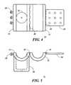
- FIG. 1is an oblique view of a fluid flow control device according to the present invention.
- FIG. 2is a front view of a body fluid flow control device in a closed position.
- FIG. 3is a cross section of the device shown in FIG. 2 .
- FIG. 4is a top view of a device in an open position according to the present invention.
- FIG. 5is a front view of the device in its open position.
- FIG. 6is a front view of the device with the plunger in a constricting position.
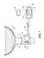
- FIG. 7is an illustration of a device according to the invention shown engaging a human urethra.
- FIG. 1there is shown an oblique view of a body fluid flow control device 10 according to the invention.
- the device 10has many possible applications including use as a remedy for incontinence.
- the fluid flow control device 10is a two piece assembly comprising a hollow cylindrical shape formed by coupling a first cylinder casing shell 12 and a second cylinder casing shell 14 .
- a host body canali.e., any tube within the human body
- the device 10is designed such that it engages the canal through which flow is to be controlled.
- the devicealso comprises a casing 16 containing a piston-like mechanism for driving a plunger (shown in other Figures) into the hollow portion of the device to restrict fluid flow through the canal enveloped by the device 10 .
- the piston-like mechanismis preferably an electromechanical solenoid but any hydraulic, pneumatic, or equivalent piston-like mechanism can be used.
- a surgeonwould introduce the device 10 into a host by making an incision providing access to the urethra. This is done according to a commonly used surgical protocol for exposing and “freeing” the urethra from its surrounding tissue. The removal of sphincter muscle is optional to the surgeon. Then cylinder shells 12 and 14 are placed around the exposed and freed portion of the urethra with the hinged side of the device 10 being placed on the back side of the urethra. The device 10 is locked into a closed position. The device 10 is then anchored in place by suturing the urethra (in that area) using a surgical grade mesh embedded in the device's bottom collar. Once this is done the host can be “closed up” and the device 10 can then be controlled remotely from outside the host.
- FIG. 2there is shown a front view of the device 10 .
- the device 10is in the closed position such that portion 12 is locked with portion 14 by means of a hinge lock comprising a strap 26 and snap pin 28 . Any other equivalent locking means can also be used for this purpose.
- the device 10forms a hollow cylinder having an inner diameter 20 adapted to fit over the canal to be constricted.
- the dimension of the diameteris controlled by that of the urethra.
- Portion 14also includes a casing 16 for an electromechanical solenoid (shown in FIG. 3 ). The solenoid moves a plunger 18 from a free flow (or retracted) position (shown in FIG. 2) to a constricting (extended) position (shown in FIG. 6 ).
- the device 10comprises a plurality of holes or portals 15 (shown in broken lines) to allow for fluid flow into the inner portion of the device 10 allowing additional tissue growth in and around the area occupied by the device 10 .
- the holesare preferably 0.031 inches in diameter and are randomly located. However, other dimensions can also be effective. This tissue growth provides additional anchoring support and prevents necrosis of the affected original tissue in the area.
- FIG. 3there is shown a cross section taken along line 3 — 3 in FIG. 2 .
- This viewreveals the structure of a piston-like contricting device with a plunger 18 attached to a shaft 24 activated by the solenoid 22 .
- the plungerpresses against the urethra while the other side of the device 10 acts as a “back wall” to restrict or prevent fluid flow.
- the plunger 18can be electronically activated in a series of increased power surges such that the device 10 can be programmed to open or close via a series of ever increasing (or decreasing) stepping motions.
- the plunger 18is designed with ridges that provide three pressure points against the urethra. As in the case of the holes 15 , this structure prevents necrosis of the affected tissue and affords more positive fluid shut off.
- a pair of teflon-coated electrical wires 30are used to conduct electrical current into the solenoid to activate the movement of the plunger 18 .
- Lead wireswill run (internally) from the internally installed device 10 to the internally installed “switching” mechanism and power supply 50 (shown in FIG. 7 ).
- the connection of wires 30is made such that the entry points of the wires into the device 10 are hermetically sealed to prevent fluid from entering into device 10 .
- the implantation site of the power supplye.g., batteries
- the power supplyis such that the power supply can be replaced with a simple outpatient procedure using only local anesthetic.
- FIG. 4is a top view of an open device 10 .
- Device portion 14is pivotally attached to portion 12 by means of a hinge 32 and can be locked into the closed position by pivoting the two halves together and then snapping the clamp 26 into snapping pins 28 (which are aligned to their corresponding holes in the clamp 26 ).
- the clamp 26is pivotally attached to the shell 12 by means of a hinge 34 .
- portion 12would not be pivotally attached to portion 14 but could be placed together and then clamped into place with two clamps such as clamp 26 , or other equivalent means.
- any known locking meanshaving the desired function can also be used.
- the device 10is preferably made from a light, corrosion-resistant material such as durable inert plastics or stainless steel, chosen to maximize its useful life.
- the casingmust be impervious to liquids.
- the device 10is powered by a power supply installed in a nearby area of the lower abdomen and is controlled by a switch embedded in the subcutaneous wall of the patient's abdomen. The switch is operated by an external triggering unit commanded by the patient.
- the device 10is shown having a cylindrical shape, it can comprise any other shape that is suitable for engaging an interior body tube such as the urethra. Moreover, the device 10 can be designed in other embodiments to engage other body tubes or canals. Thus, other possible applications for devices in accordance with the invention include a reversible vasectomy device, a nutrition absorbtion device, or a reversible nutrition absobtion device to treat extreme obesity.
- the device 10engages a urethra 40 .
- the device 10preferably surrounds the urethra in the general location of the sphincter muscle.
- the urethrais part of the urinary tract which also comprises a bladder 42 which contains liquid waste matter 44 .
- the device 10is coupled to a control device 50 which comprises a reed switch 52 that is controlled from a magnetic device 60 outside the host body.
- the device 50is hermetically sealed and preferably has a Silicon casing.
- the control device 50also comprises a battery 54 which is easily removable and replacable.
- the device 10may comprise a number of triggering mechanism options from a touch sensor to infrared, voice or sound activation.
- control devicescan be used to control the operation of device 10 by a user.
- the device 10is surgically implanted into a human host such that the host will require a control mechanism that can be operated from outside the host.
- a control mechanismthat can be operated from outside the host.
- One simple examplewould be a switch implanted just underneath the host's skin such that the host can activate it by pressing on the skin above the switch.
- Any of several known pressure-activated switcheswill do provided that they are made from a suitable corrosion resistant material.
- Another control mechanismcould be a smart card having a coil or other means for generating electromagnetic signals that control a control device inside the host.
Landscapes
- Health & Medical Sciences (AREA)
- Urology & Nephrology (AREA)
- General Health & Medical Sciences (AREA)
- Public Health (AREA)
- Engineering & Computer Science (AREA)
- Biomedical Technology (AREA)
- Heart & Thoracic Surgery (AREA)
- Vascular Medicine (AREA)
- Life Sciences & Earth Sciences (AREA)
- Animal Behavior & Ethology (AREA)
- Oral & Maxillofacial Surgery (AREA)
- Transplantation (AREA)
- Veterinary Medicine (AREA)
- Cardiology (AREA)
- Prostheses (AREA)
- Flow Control (AREA)
- Paper (AREA)
- External Artificial Organs (AREA)
- Infusion, Injection, And Reservoir Apparatuses (AREA)
- Cyclones (AREA)
Abstract
Description
Not applicable.
1. Field of the Invention
The invention disclosed broadly relates to the field of medical devices, and more particularly relates to the field of devices for the control of fluid flow within the urethra.
2. Description of the Related Art
Incontinence is a condition wherein persons lose control over their voluntary, urinary function. The condition can arise from various causes. These causes include a variety of related and unrelated diseases, aging, and deterioration of the voluntary urethra sphincter muscle. The costs and inconvenience to persons suffering from this condition are great. Several remedies exist for this that are known in the prior art. Among these, the most common are surgical corrections (minor and major), drugs, and devices which serve to capture discharges (i.e., “capture” or diaper systems). Another solution is to place a patch over the urinary orifice to prevent unwanted discharge. Possibly the most effective solution to date is the use of artificial sphincters. These devices are surgically installed and are hydraulically or pneumatically driven, operating by inflation of ballasts to suppress fluid flow. However, control of these devices is not always easy and is often inconvenient. Accordingly, there is a need for an improved method and apparatus to control the urinary function.
Briefly, in accordance with the invention, an implantable apparatus for controlling fluid flow within a host body comprises: engaging means for engaging a canal within the body, said canal having a diameter; constricting means for reducing the diameter of the canal; and control means for causing the constriction means to reduce the diameter of the canal.
FIG. 1 is an oblique view of a fluid flow control device according to the present invention.
FIG. 2 is a front view of a body fluid flow control device in a closed position.
FIG. 3 is a cross section of the device shown in FIG.2.
FIG. 4 is a top view of a device in an open position according to the present invention.
FIG. 5 is a front view of the device in its open position.
FIG. 6 is a front view of the device with the plunger in a constricting position.
FIG. 7 is an illustration of a device according to the invention shown engaging a human urethra.
Referring to FIG. 1, there is shown an oblique view of a body fluidflow control device 10 according to the invention. Thedevice 10 has many possible applications including use as a remedy for incontinence.
The fluidflow control device 10 is a two piece assembly comprising a hollow cylindrical shape formed by coupling a firstcylinder casing shell 12 and a secondcylinder casing shell 14. When thefirst shell 12 is coupled with thesecond shell 14, there is assembled a cylindrical tube with aninner diameter 20 which is well suited for fitting around a host body canal (i.e., any tube within the human body) such as the urethra. Thedevice 10 is designed such that it engages the canal through which flow is to be controlled. The device also comprises acasing 16 containing a piston-like mechanism for driving a plunger (shown in other Figures) into the hollow portion of the device to restrict fluid flow through the canal enveloped by thedevice 10. The piston-like mechanism is preferably an electromechanical solenoid but any hydraulic, pneumatic, or equivalent piston-like mechanism can be used.
A surgeon would introduce thedevice 10 into a host by making an incision providing access to the urethra. This is done according to a commonly used surgical protocol for exposing and “freeing” the urethra from its surrounding tissue. The removal of sphincter muscle is optional to the surgeon. Thencylinder shells device 10 being placed on the back side of the urethra. Thedevice 10 is locked into a closed position. Thedevice 10 is then anchored in place by suturing the urethra (in that area) using a surgical grade mesh embedded in the device's bottom collar. Once this is done the host can be “closed up” and thedevice 10 can then be controlled remotely from outside the host.
Referring to FIG. 2, there is shown a front view of thedevice 10. Thedevice 10 is in the closed position such thatportion 12 is locked withportion 14 by means of a hinge lock comprising astrap 26 andsnap pin 28. Any other equivalent locking means can also be used for this purpose.
In the preferred embodiment, thedevice 10 forms a hollow cylinder having aninner diameter 20 adapted to fit over the canal to be constricted. When designed as an incontinence remedy, the dimension of the diameter is controlled by that of the urethra.Portion 14 also includes acasing 16 for an electromechanical solenoid (shown in FIG.3). The solenoid moves aplunger 18 from a free flow (or retracted) position (shown in FIG. 2) to a constricting (extended) position (shown in FIG.6).
Thedevice 10 comprises a plurality of holes or portals15 (shown in broken lines) to allow for fluid flow into the inner portion of thedevice 10 allowing additional tissue growth in and around the area occupied by thedevice 10. The holes are preferably 0.031 inches in diameter and are randomly located. However, other dimensions can also be effective. This tissue growth provides additional anchoring support and prevents necrosis of the affected original tissue in the area.
Referring to FIG. 3, there is shown a cross section taken along line3—3 in FIG.2. This view reveals the structure of a piston-like contricting device with aplunger 18 attached to ashaft 24 activated by thesolenoid 22. The plunger presses against the urethra while the other side of thedevice 10 acts as a “back wall” to restrict or prevent fluid flow. Theplunger 18 can be electronically activated in a series of increased power surges such that thedevice 10 can be programmed to open or close via a series of ever increasing (or decreasing) stepping motions. Theplunger 18 is designed with ridges that provide three pressure points against the urethra. As in the case of theholes 15, this structure prevents necrosis of the affected tissue and affords more positive fluid shut off.
A pair of teflon-coatedelectrical wires 30 are used to conduct electrical current into the solenoid to activate the movement of theplunger 18. Lead wires will run (internally) from the internally installeddevice 10 to the internally installed “switching” mechanism and power supply50 (shown in FIG.7). The connection ofwires 30 is made such that the entry points of the wires into thedevice 10 are hermetically sealed to prevent fluid from entering intodevice 10. The implantation site of the power supply (e.g., batteries) is such that the power supply can be replaced with a simple outpatient procedure using only local anesthetic.
Referring to FIGS. 4 and 5, the open position of thedevice 10 is illustrated. When thedevice 10 is first introduced into a host, it is in the open position to enable the engagement of the device to the urethra. FIG. 4 is a top view of anopen device 10.Device portion 14 is pivotally attached toportion 12 by means of ahinge 32 and can be locked into the closed position by pivoting the two halves together and then snapping theclamp 26 into snapping pins28 (which are aligned to their corresponding holes in the clamp26). Theclamp 26 is pivotally attached to theshell 12 by means of ahinge 34. In another embodiment,portion 12 would not be pivotally attached toportion 14 but could be placed together and then clamped into place with two clamps such asclamp 26, or other equivalent means. Moreover, any known locking means having the desired function can also be used.
Thedevice 10 is preferably made from a light, corrosion-resistant material such as durable inert plastics or stainless steel, chosen to maximize its useful life. The casing must be impervious to liquids. Thedevice 10 is powered by a power supply installed in a nearby area of the lower abdomen and is controlled by a switch embedded in the subcutaneous wall of the patient's abdomen. The switch is operated by an external triggering unit commanded by the patient.
Although thedevice 10 is shown having a cylindrical shape, it can comprise any other shape that is suitable for engaging an interior body tube such as the urethra. Moreover, thedevice 10 can be designed in other embodiments to engage other body tubes or canals. Thus, other possible applications for devices in accordance with the invention include a reversible vasectomy device, a nutrition absorbtion device, or a reversible nutrition absobtion device to treat extreme obesity.
Referring to FIG. 7, there is shown an illustration of thedevice 10 engaging aurethra 40. Thedevice 10 preferably surrounds the urethra in the general location of the sphincter muscle. The urethra is part of the urinary tract which also comprises abladder 42 which containsliquid waste matter 44. Thedevice 10 is coupled to acontrol device 50 which comprises areed switch 52 that is controlled from amagnetic device 60 outside the host body. Thedevice 50 is hermetically sealed and preferably has a Silicon casing. Thecontrol device 50 also comprises abattery 54 which is easily removable and replacable. Thedevice 10 may comprise a number of triggering mechanism options from a touch sensor to infrared, voice or sound activation. Any of several well-known control devices can be used to control the operation ofdevice 10 by a user. As mentioned above, thedevice 10 is surgically implanted into a human host such that the host will require a control mechanism that can be operated from outside the host. One simple example would be a switch implanted just underneath the host's skin such that the host can activate it by pressing on the skin above the switch. Any of several known pressure-activated switches will do provided that they are made from a suitable corrosion resistant material. Another control mechanism could be a smart card having a coil or other means for generating electromagnetic signals that control a control device inside the host.
Although a specific embodiment of the invention has been disclosed, it will be understood by those having skill in the art that changes can be made to this specific embodiment without departing from the spirit and scope of the invention. The scope of the invention is not to be restricted, therefore, to the specific embodiment, and it is intended that the appended claims cover any and all such applications, modifications, and embodiments within the scope of the present invention.
Claims (30)
1. An implantable apparatus for controlling fluid flow through a canal within a host body without having to sever the canal (i) to implant said implantable apparatus inside the host body or (ii) to operate said implantable apparatus following implantation thereof, said implantable apparatus comprising:
a hollow housing for positioning around a selected area of a canal within the host body;
an electrically operated piston comprising a slidable shaft connected to a plunger positioned within said hollow housing for driving the plunger to an extended position and for retracting the plunger to a retracted position; and
a control device for selectively moving said electrically operated piston between the extended position to constrict a portion of the selected area of the canal to reduce or stop fluid flow through the canal and the retracted positioned to open the constricted portion of the selected area of the canal to permit fluid flow through the canal to control fluid flow through the canal.
2. An implantable apparatus of claim1 wherein said hollow housing comprises a first engaging element and a second engaging element for coupling to the first engaging element, so that said hollow housing completely encircles the canal following implantation of said implantable apparatus.
3. An implantable apparatus of claim2 wherein the first engaging element comprises a first cylindrical half shell and the second engaging element comprises a second cylindrical half shell movable from an open position to a closed position wherein the first and second cylinder half shells when coupled together form a hollow cylinder having an inner diameter adapted to generally fit around the canal.
4. An implantable apparatus of claim3 wherein the first cylindrical half shell is pivotally connected to the second cylindrical half shell such that the second cylindrical half shell is movable from an open position to a closed position.
5. An implantable apparatus of claim4 further comprising a locking member for locking the first and second cylindrical half shells into the locked position when the first and second cylindrical half shells are coupled together.
6. An implantable apparatus of claim1 wherein said hollow housing comprises a generally cylindrical shape having an inner diameter suitable for surrounding a human urethra.
7. An implantable apparatus of claim1, wherein said implantable apparatus further comprises a solenoid for activating said electrically operated piston.
8. An implantable apparatus of claim7, wherein said implantable apparatus further includes a hollow casing connected perpendicular to said hollow housing for housing said electrically operated piston.
9. An implantable apparatus of claim7, wherein said hollow housing further includes a mesh embedded therein to which a portion of the selected area of the canal is sutured following implantation thereof, so that said implantable device is anchored in place.
10. An implantable apparatus of claim1, wherein the plunger includes a front face for engaging the canal, the front face having thereon more than one pressure point for contacting and applying pressure to the portion of the selected area of the canal when said electrically operated piston is engaged with the canal.
11. An implantable apparatus of claim10, wherein the pressure points are in the form of ridges.
12. An implantable apparatus of claim1, wherein said hollow housing comprises at least two cylindrical shells that fit together to form a hollow cylindrical casing wherein the cylindrical shells include a plurality of portals for allowing body fluids, from outside the canal, to flow into the hollow cylindrical casing.
13. An implantable apparatus of claim1 wherein said control device comprises an electromagnetic field generator for generating an electromagnetic field comprising a code for activating said electrically operated piston.
14. An implantable apparatus of claim1, wherein said control device comprises a magnet for activating said electrically operated piston, said control device further including a switch activated by the magnet being waved in the proximity of the switch to activate said electrically operated piston.
15. A method for controlling the flow of a body fluid within a canal in a host body comprising the steps of:
making an incision in the host body at a selected location to provide access to a selected canal;
placing an implantable body fluid control device having an electrically operated piston at a selected location around the selected canal to implant said implantable device inside the host body without severing the selected canal to implant said implantable device around the selected canal or operate said implantable device following said implantation thereof; and
locking said implantable device in a closed position following said implantation, so that said constricting piston when operated engages and sufficiently constricts a selected portion of the selected canal to control the flow of the body fluid through the selected canal.
16. A method of claim15, wherein said method further comprises removing the sphincter muscle from the host.
17. A method of claim15, wherein said step of placing said implantable device at a selected location around the selected canal further comprises placing a first shell at the selected location around the selected canal and coupling a second shell to the first shell, so that said implantable device surrounds at least a portion of the selected canal.
18. An implantable fluid flow control device for fitting around a body tube without having to sever the body tube to implant said implantable device or to operate said implantable device following implantation thereof, said implantable device comprising:
a first shell;
a second shell;
a hinge for pivotally coupling the first shell to the second shell to form a hollow assembly around the body tube having an open position and a closed position;
a lock for locking said hollow assembly into the closed position;
a constricting device for restricting fluid flow through the body tube; and
a control device for selectively moving said constricting device between an extended position to constrict a portion of the selected area of the canal to reduce or stop fluid flow through the canal and a retracted positioned to open the constricted portion of the selected area of the canal to permit fluid flow through the canal, following the implantation of the implantable fluid flow control device.
19. An implantable device of claim18, wherein said first and second shells include portals for permitting fluid from outside the canal to flow therethrough.
20. The device of claim19, wherein said constricting device comprises a plunger and a solenoid for moving the plunger against the body tube to constrict the body tube when activated, so that fluid flow through the constricted body tube is restricted or stopped.
21. An implantable apparatus for controlling fluid flow through a canal within a host body without having to sever the canal to implant said implantable apparatus, said implantable apparatus comprising:
an engaging component for engaging a canal within the body, the canal having a diameter, said engaging component comprising a plurality of portals for allowing body fluid flow outside the canal;
a constricting element for restricting fluid flow through the canal when said constricting element is activated; and
a control device for activating said constriction element to reduce the diameter of the canal.
22. An implantable apparatus of claim21 wherein said control device includes a magnetic switch.
23. An implantable apparatus of claim21, wherein said constricting element includes a sliding cylindrical shaft that reciprocates in a tubular housing.
24. A method for controlling the flow of a body fluid within a canal in a host body comprising the steps of:
making an incision in the host body to provide access to a selected canal;
placing a controllable constricting device around the selected canal without severing the selected canal;
locking the controllable constricting device in a closed position, wherein the canal is engaged by the constricting device, so that, when the constricting device is activated, fluid flow through the selected canal is controlled; and
removing the sphincter muscle from the host.
25. An implantable apparatus for selectively controlling fluid flow through a canal having internal and external walls and diameters, respectively, in a host body without having to sever the canal to implant said implantable apparatus in the host body or to operate said implantable apparatus following implantation thereof, said implantable apparatus comprising:
a stop device positioned adjacent a selected portion of the external wall of a selected canal through which fluid flows following implantation of said implantable apparatus into the body host;
an electrically operated constricting piston having a sliding plunger for engaging a certain area of the external wall of the selected canal which is opposite the selected area of the external wall against which said stop device is located when said constricting piston is activated; and
a control device for selectively activating said electrically operated constricting piston,
whereby, when said control device is activated, the plunger when retracted extends to an extended position to restrict the certain area of the exterior wall of the selected canal against said stop device to reduce the internal diameter of the selected canal located between the plunger and said stop device to reduce or stop fluid flow through the selected canal, and the plunger when extended retracts to a retracted position to open the selected canal to permit fluid flow there through.
26. An implantable device of claim25 further comprising a hollow cylinder for surrounding the selected canal of which said stop device and said constricting piston are a part, said hollow cylinder having a plurality of portals for allowing fluid outside of the selected canal to flow through said portals.
27. An implantable device of claim25, wherein said implantable device further includes a mesh embedded therein to which a portion of the selected canal is sutured following implantation thereof to anchor said implantable device.
28. An implantable incontinence apparatus for selectively controlling urine flow from a bladder through an urethra having internal and external walls and diameters, respectively, in a host body without having to sever the urethra to implant said implantable apparatus in the host body or to operate said implantable device following implantation thereof, said implantable apparatus comprising:
a hollow housing, wherein said hollow housing has a plurality of portals for permitting fluid from outside of the urethra to flow into said hollow housing to promote tissue growth and anchor said implantable incontinence device following implantation thereof,
a stop device within said hollow housing and positioned adjacent a selected portion of the external wall of the urethra through which urine flows following implantation of said implantable incontinence apparatus into the body host;
an electrically operated constricting piston having a sliding shaft connected to a plunger for engaging a certain area of the external wall of the urethra which is opposite the selected area of the external wall of the urethra against which said stop device is located when said electrically operated constricting piston is activated, said plunger having a front on which more than one ridge is formed to create separate pressure points against the urethra when the plunger engages the urethra;
a control device for selectively activating said constricting piston;
whereby, when said control device is activated, the plunger when retracted extends to an extended position to restrict to restrict the certain area of the exterior wall of the urethra against said stop device to reduce the internal diameter of the urethra located between the plunger and said stop device to reduce or stop urine flow through the urethra, and the plunger when extended retracts to a retracted position to open the urethral to permit urine flow there through.
29. An incontinence implantable device of claim28, wherein said implantable incontinence device further includes a mesh embedded therein to which the urethra is sutured following implantation thereof to anchor said implantable incontinence device.
30. An incontinence implantable device of claim25, wherein said implantable incontinence device further includes a mesh embedded therein to which the urethra is sutured following implantation thereof to anchor said implantable incontinence device.
Priority Applications (13)
| Application Number | Priority Date | Filing Date | Title |
|---|---|---|---|
| US09/048,823US6319191B1 (en) | 1998-03-26 | 1998-03-26 | Implantable body fluid flow control device |
| AU32008/99AAU757862B2 (en) | 1998-03-26 | 1999-03-23 | Body fluid flow control device |
| KR1019997010975AKR20010013002A (en) | 1998-03-26 | 1999-03-23 | Body fluid flow control device |
| MXPA99010974AMXPA99010974A (en) | 1998-03-26 | 1999-03-23 | Body fluid flow control device. |
| BRPI9904891ABR9904891B8 (en) | 1998-03-26 | 1999-03-23 | an implantable fluid flow control device for installation around a body tube. |
| PCT/US1999/006394WO1999048438A1 (en) | 1998-03-26 | 1999-03-23 | Body fluid flow control device |
| CA2291726ACA2291726C (en) | 1998-03-26 | 1999-03-23 | Body fluid flow control device |
| ES99914083TES2324505T3 (en) | 1998-03-26 | 1999-03-23 | BODY FLUID FLOW CONTROL DEVICE. |
| EP99914083AEP0981307B1 (en) | 1998-03-26 | 1999-03-23 | Body fluid flow control device |
| DE69940585TDE69940585D1 (en) | 1998-03-26 | 1999-03-23 | FLOW RATE DEVICE FOR BODY FLUID |
| AT99914083TATE425717T1 (en) | 1998-03-26 | 1999-03-23 | FLOW CONTROL DEVICE FOR BODY FLUID |
| JP54848099AJP4339933B2 (en) | 1998-03-26 | 1999-03-23 | Body fluid flow control device |
| NO995773ANO995773L (en) | 1998-03-26 | 1999-11-25 | Device for controlling flow of body fluid |
Applications Claiming Priority (1)
| Application Number | Priority Date | Filing Date | Title |
|---|---|---|---|
| US09/048,823US6319191B1 (en) | 1998-03-26 | 1998-03-26 | Implantable body fluid flow control device |
Publications (1)
| Publication Number | Publication Date |
|---|---|
| US6319191B1true US6319191B1 (en) | 2001-11-20 |
Family
ID=21956633
Family Applications (1)
| Application Number | Title | Priority Date | Filing Date |
|---|---|---|---|
| US09/048,823Expired - LifetimeUS6319191B1 (en) | 1998-03-26 | 1998-03-26 | Implantable body fluid flow control device |
Country Status (13)
| Country | Link |
|---|---|
| US (1) | US6319191B1 (en) |
| EP (1) | EP0981307B1 (en) |
| JP (1) | JP4339933B2 (en) |
| KR (1) | KR20010013002A (en) |
| AT (1) | ATE425717T1 (en) |
| AU (1) | AU757862B2 (en) |
| BR (1) | BR9904891B8 (en) |
| CA (1) | CA2291726C (en) |
| DE (1) | DE69940585D1 (en) |
| ES (1) | ES2324505T3 (en) |
| MX (1) | MXPA99010974A (en) |
| NO (1) | NO995773L (en) |
| WO (1) | WO1999048438A1 (en) |
Cited By (46)
| Publication number | Priority date | Publication date | Assignee | Title |
|---|---|---|---|---|
| US20030144648A1 (en)* | 2000-02-14 | 2003-07-31 | Peter Forsell | Hydraulic urinary incontinence treatment apparatus |
| US6689046B2 (en)* | 2000-09-29 | 2004-02-10 | Precision Medical Devices, Inc. | Body fluid flow control method and device |
| US20040133219A1 (en)* | 2002-07-29 | 2004-07-08 | Peter Forsell | Multi-material constriction device for forming stoma opening |
| US20040147886A1 (en)* | 2002-11-06 | 2004-07-29 | Aram Bonni | Patient-adjustable incontinence device (AID) |
| US20040176797A1 (en)* | 2003-03-04 | 2004-09-09 | Nmt Medical, Inc. | Magnetic attachment systems |
| US6805687B2 (en) | 2002-03-22 | 2004-10-19 | Codman & Shurtleff, Inc. | Infusion pump with access regulator |
| US20040242956A1 (en)* | 2002-07-29 | 2004-12-02 | Scorvo Sean K. | System for controlling fluid in a body |
| US20050267324A1 (en)* | 2004-05-07 | 2005-12-01 | Novatek Medical, Llc | Urethral occlusive assembly for preventing urinary incontinence |
| US20060167337A1 (en)* | 2003-01-31 | 2006-07-27 | Peter Forsell | Careful incontinence treatment apparatus |
| US20060195009A1 (en)* | 2004-12-06 | 2006-08-31 | Sam Drager | Apparatus and method for correcting urinary incontinence |
| WO2009000081A1 (en)* | 2007-06-28 | 2008-12-31 | Antoine Trubiano | Urethra pressure control valve to control incontinence |
| US20100179376A1 (en)* | 2007-05-29 | 2010-07-15 | Kassab Ghassan S | Devices, systems, and methods for deforming a body channel |
| US7931582B2 (en) | 2000-02-11 | 2011-04-26 | Obtech Medical Ag | Controlled impotence treatment |
| US8096939B2 (en) | 2000-02-10 | 2012-01-17 | Obtech Medical Ag | Urinary incontinence treatment with wireless energy supply |
| US8096938B2 (en) | 1999-08-12 | 2012-01-17 | Obtech Medical Ag | Controlled anal incontinence disease treatment |
| US8126558B2 (en) | 2000-02-14 | 2012-02-28 | Obtech Medical Ag | Controlled penile prosthesis |
| US8287444B2 (en) | 2000-02-10 | 2012-10-16 | Obtech Medical Ag | Mechanical impotence treatment apparatus |
| US8290594B2 (en) | 2000-02-11 | 2012-10-16 | Obtech Medical Ag | Impotence treatment apparatus with energy transforming means |
| US8313423B2 (en) | 2000-02-14 | 2012-11-20 | Peter Forsell | Hydraulic anal incontinence treatment |
| US20130197316A1 (en)* | 2010-10-05 | 2013-08-01 | Johnathan A. Engh | Endoscopic ports for minimally invasive surgical access and methods of use thereof |
| US8509894B2 (en) | 2008-10-10 | 2013-08-13 | Milux Holding Sa | Heart help device, system, and method |
| US8545384B2 (en) | 1999-08-12 | 2013-10-01 | Obtech Medical Ag | Anal incontinence disease treatment with controlled wireless energy supply |
| US8556796B2 (en) | 2000-02-10 | 2013-10-15 | Obtech Medical Ag | Controlled urinary incontinence treatment |
| US8600510B2 (en) | 2008-10-10 | 2013-12-03 | Milux Holding Sa | Apparatus, system and operation method for the treatment of female sexual dysfunction |
| US8636809B2 (en) | 2008-01-29 | 2014-01-28 | Milux Holding Sa | Device for treating obesity |
| US8678997B2 (en) | 2000-02-14 | 2014-03-25 | Obtech Medical Ag | Male impotence prosthesis apparatus with wireless energy supply |
| US8696745B2 (en) | 2008-10-10 | 2014-04-15 | Kirk Promotion Ltd. | Heart help device, system, and method |
| US8734318B2 (en) | 2000-02-11 | 2014-05-27 | Obtech Medical Ag | Mechanical anal incontinence |
| US8740766B2 (en) | 2010-03-16 | 2014-06-03 | Pelvalon, Inc. | Intra-vaginal devices and methods for treating fecal incontinence |
| US8764627B2 (en) | 2000-02-14 | 2014-07-01 | Obtech Medical Ag | Penile prosthesis |
| US8874215B2 (en) | 2008-10-10 | 2014-10-28 | Peter Forsell | System, an apparatus, and a method for treating a sexual dysfunctional female patient |
| US8961448B2 (en) | 2008-01-28 | 2015-02-24 | Peter Forsell | Implantable drainage device |
| US9072578B2 (en) | 2010-03-16 | 2015-07-07 | Pelvalon, Inc. | Intra-vaginal device for fecal incontinence |
| US20160015392A1 (en)* | 2013-03-15 | 2016-01-21 | Mayo Foundation For Medical Education And Research | Luminal compression device |
| US9278158B2 (en) | 2002-07-29 | 2016-03-08 | Peter Forsell | Multi-material incontinence treatment construction device |
| US9289278B2 (en) | 2010-03-16 | 2016-03-22 | Pelvalon, Inc. | Intra-vaginal devices and methods for treating fecal incontinence |
| US9427301B2 (en) | 2002-07-29 | 2016-08-30 | Peter Forsell | Durable implant |
| EP2967871A4 (en)* | 2013-03-14 | 2016-12-21 | Univ Texas | IMPLANTABLE MEDICAL APPARATUS AND SYSTEMS |
| US9855125B2 (en) | 2009-11-30 | 2018-01-02 | Cvdevices, Llc | Devices, systems, and methods for deforming a body channel |
| US9949812B2 (en) | 2009-07-17 | 2018-04-24 | Peter Forsell | Vaginal operation method for the treatment of anal incontinence in women |
| US9974635B2 (en) | 2013-02-14 | 2018-05-22 | Pelvalon, Inc. | Intra-vaginal devices and methods for treating fecal incontinence |
| US10219898B2 (en) | 2008-10-10 | 2019-03-05 | Peter Forsell | Artificial valve |
| US10684154B2 (en) | 2016-12-12 | 2020-06-16 | Ventbuster Holdings Inc. | Gas meter and associated methods |
| US10952836B2 (en) | 2009-07-17 | 2021-03-23 | Peter Forsell | Vaginal operation method for the treatment of urinary incontinence in women |
| US11123171B2 (en) | 2008-10-10 | 2021-09-21 | Peter Forsell | Fastening means for implantable medical control assembly |
| US20210378811A1 (en)* | 2008-10-10 | 2021-12-09 | Peter Forsell | Fastening means for implantable medical control assembly |
Families Citing this family (8)
| Publication number | Priority date | Publication date | Assignee | Title |
|---|---|---|---|---|
| US7011621B2 (en)* | 2000-09-29 | 2006-03-14 | Precision Medical Devices, Inc. | Body fluid flow control method and device |
| EP1343112A1 (en)* | 2002-03-08 | 2003-09-10 | EndoArt S.A. | Implantable device |
| ES2876250T3 (en)* | 2007-10-11 | 2021-11-12 | Implantica Patent Ltd | Apparatus for controlling flow in a body organ |
| WO2013091730A1 (en) | 2011-12-23 | 2013-06-27 | Myopowers Medical Technologies Sa | Medical device comprising an artificial contractile structure |
| US11246695B2 (en) | 2011-12-23 | 2022-02-15 | MyoPowers Medical Technologies France SAS | Medical device comprising an artificial contractile structure |
| US10441399B2 (en) | 2012-12-21 | 2019-10-15 | MyoPowers Medical Technologies France SAS | Medical device comprising an artificial contractile structure |
| US11896823B2 (en) | 2017-04-04 | 2024-02-13 | Btl Healthcare Technologies A.S. | Method and device for pelvic floor tissue treatment |
| KR102405316B1 (en)* | 2020-07-08 | 2022-06-02 | 가톨릭대학교 산학협력단 | Artificial Urethral Sphincter With Hinge Structure |
Citations (21)
| Publication number | Priority date | Publication date | Assignee | Title |
|---|---|---|---|---|
| US3357434A (en) | 1964-04-06 | 1967-12-12 | Avco Corp | Inductively linked receiver |
| US3419008A (en)* | 1966-02-24 | 1968-12-31 | Paul J. Plishner | Magnetically actuated valve clamp for urethra control |
| FR1566202A (en) | 1967-12-27 | 1969-05-09 | ||
| GB1174814A (en) | 1966-02-10 | 1969-12-17 | Rolf Dieter Grunert | Device for Occlusion and Release of Natural or Artificially Constructed Ducts in the Human or Animal Body |
| US3924631A (en) | 1973-12-06 | 1975-12-09 | Altair Inc | Magnetic clamp |
| US3926175A (en) | 1974-06-03 | 1975-12-16 | James H Allen | Implantable valve for medical purposes |
| US4024855A (en) | 1974-12-30 | 1977-05-24 | Louis Bucalo | Magnetic filamentary structure and method for using the same |
| US4053952A (en) | 1975-10-10 | 1977-10-18 | The United States Of America As Represented By The Secretary Of The Department Of Health, Education And Welfare | Magnetic fluid actuated control valve, relief valve and pump |
| US4352960A (en) | 1980-09-30 | 1982-10-05 | Baptist Medical Center Of Oklahoma, Inc. | Magnetic transcutaneous mount for external device of an associated implant |
| US4387705A (en)* | 1980-07-15 | 1983-06-14 | Medical Engineering Corporation | Penile implant |
| US4553271A (en) | 1980-10-06 | 1985-11-19 | University Of Utah Research Institute | Artificial sphincter apparatus and method |
| WO1987007132A1 (en) | 1986-05-22 | 1987-12-03 | Ballobes Aps | Method and device for performing a puncturing work on an inflated balloon-like object implanted in a patient |
| US4777949A (en) | 1987-05-08 | 1988-10-18 | Metatech Corporation | Surgical clip for clamping small blood vessels in brain surgery and the like |
| US4994019A (en) | 1989-07-28 | 1991-02-19 | Micro-Magnetics, Inc. | Magnetic occluding device |
| FR2658084A1 (en) | 1990-02-14 | 1991-08-16 | Chouard Claude Henri | Improvements to stimulating devices comprising elements implanted in living organisms |
| WO1992016162A1 (en)* | 1991-03-13 | 1992-10-01 | Greater Glasgow Health Board | Prosthetic anal sphincter |
| FR2688693A1 (en) | 1992-03-19 | 1993-09-24 | Ferriere Xavier | Artificial sphincter, especially urethral (urinary) sphincter |
| US5509888A (en)* | 1994-07-26 | 1996-04-23 | Conceptek Corporation | Controller valve device and method |
| US5562598A (en) | 1994-09-20 | 1996-10-08 | Whalen Biomedical Inc. | Artificial urethral sphincter |
| WO1998023232A1 (en)* | 1996-11-29 | 1998-06-04 | Claude Cusset | Prosthetic urinary sphincter with external control |
| FR2769491A1 (en) | 1997-10-15 | 1999-04-16 | Patrick Sangouard | Artificial sphincter for medical use in control of incontinence |
- 1998
- 1998-03-26USUS09/048,823patent/US6319191B1/ennot_activeExpired - Lifetime
- 1999
- 1999-03-23ATAT99914083Tpatent/ATE425717T1/ennot_activeIP Right Cessation
- 1999-03-23KRKR1019997010975Apatent/KR20010013002A/ennot_activeAbandoned
- 1999-03-23DEDE69940585Tpatent/DE69940585D1/ennot_activeExpired - Lifetime
- 1999-03-23ESES99914083Tpatent/ES2324505T3/ennot_activeExpired - Lifetime
- 1999-03-23MXMXPA99010974Apatent/MXPA99010974A/enactiveIP Right Grant
- 1999-03-23BRBRPI9904891Apatent/BR9904891B8/ennot_activeIP Right Cessation
- 1999-03-23EPEP99914083Apatent/EP0981307B1/ennot_activeExpired - Lifetime
- 1999-03-23AUAU32008/99Apatent/AU757862B2/ennot_activeExpired
- 1999-03-23WOPCT/US1999/006394patent/WO1999048438A1/enactiveIP Right Grant
- 1999-03-23JPJP54848099Apatent/JP4339933B2/ennot_activeExpired - Lifetime
- 1999-03-23CACA2291726Apatent/CA2291726C/ennot_activeExpired - Lifetime
- 1999-11-25NONO995773Apatent/NO995773L/ennot_activeApplication Discontinuation
Patent Citations (21)
| Publication number | Priority date | Publication date | Assignee | Title |
|---|---|---|---|---|
| US3357434A (en) | 1964-04-06 | 1967-12-12 | Avco Corp | Inductively linked receiver |
| GB1174814A (en) | 1966-02-10 | 1969-12-17 | Rolf Dieter Grunert | Device for Occlusion and Release of Natural or Artificially Constructed Ducts in the Human or Animal Body |
| US3419008A (en)* | 1966-02-24 | 1968-12-31 | Paul J. Plishner | Magnetically actuated valve clamp for urethra control |
| FR1566202A (en) | 1967-12-27 | 1969-05-09 | ||
| US3924631A (en) | 1973-12-06 | 1975-12-09 | Altair Inc | Magnetic clamp |
| US3926175A (en) | 1974-06-03 | 1975-12-16 | James H Allen | Implantable valve for medical purposes |
| US4024855A (en) | 1974-12-30 | 1977-05-24 | Louis Bucalo | Magnetic filamentary structure and method for using the same |
| US4053952A (en) | 1975-10-10 | 1977-10-18 | The United States Of America As Represented By The Secretary Of The Department Of Health, Education And Welfare | Magnetic fluid actuated control valve, relief valve and pump |
| US4387705A (en)* | 1980-07-15 | 1983-06-14 | Medical Engineering Corporation | Penile implant |
| US4352960A (en) | 1980-09-30 | 1982-10-05 | Baptist Medical Center Of Oklahoma, Inc. | Magnetic transcutaneous mount for external device of an associated implant |
| US4553271A (en) | 1980-10-06 | 1985-11-19 | University Of Utah Research Institute | Artificial sphincter apparatus and method |
| WO1987007132A1 (en) | 1986-05-22 | 1987-12-03 | Ballobes Aps | Method and device for performing a puncturing work on an inflated balloon-like object implanted in a patient |
| US4777949A (en) | 1987-05-08 | 1988-10-18 | Metatech Corporation | Surgical clip for clamping small blood vessels in brain surgery and the like |
| US4994019A (en) | 1989-07-28 | 1991-02-19 | Micro-Magnetics, Inc. | Magnetic occluding device |
| FR2658084A1 (en) | 1990-02-14 | 1991-08-16 | Chouard Claude Henri | Improvements to stimulating devices comprising elements implanted in living organisms |
| WO1992016162A1 (en)* | 1991-03-13 | 1992-10-01 | Greater Glasgow Health Board | Prosthetic anal sphincter |
| FR2688693A1 (en) | 1992-03-19 | 1993-09-24 | Ferriere Xavier | Artificial sphincter, especially urethral (urinary) sphincter |
| US5509888A (en)* | 1994-07-26 | 1996-04-23 | Conceptek Corporation | Controller valve device and method |
| US5562598A (en) | 1994-09-20 | 1996-10-08 | Whalen Biomedical Inc. | Artificial urethral sphincter |
| WO1998023232A1 (en)* | 1996-11-29 | 1998-06-04 | Claude Cusset | Prosthetic urinary sphincter with external control |
| FR2769491A1 (en) | 1997-10-15 | 1999-04-16 | Patrick Sangouard | Artificial sphincter for medical use in control of incontinence |
Non-Patent Citations (6)
| Title |
|---|
| Derwent Summary for EP 1023002A1: Artificial Sphincter with Magnetic Control-Two Pages. |
| Derwent Summary for EP 1023002A1: Artificial Sphincter with Magnetic Control—Two Pages. |
| English abstract of FR 2658084-One Page. |
| English abstract of FR 2658084—One Page. |
| English abstract of FR 2688693-One Page. |
| English abstract of FR 2688693—One Page. |
Cited By (73)
| Publication number | Priority date | Publication date | Assignee | Title |
|---|---|---|---|---|
| US8545384B2 (en) | 1999-08-12 | 2013-10-01 | Obtech Medical Ag | Anal incontinence disease treatment with controlled wireless energy supply |
| US8096938B2 (en) | 1999-08-12 | 2012-01-17 | Obtech Medical Ag | Controlled anal incontinence disease treatment |
| US8096939B2 (en) | 2000-02-10 | 2012-01-17 | Obtech Medical Ag | Urinary incontinence treatment with wireless energy supply |
| US8602966B2 (en) | 2000-02-10 | 2013-12-10 | Obtech Medical, AG | Mechanical impotence treatment apparatus |
| US8556796B2 (en) | 2000-02-10 | 2013-10-15 | Obtech Medical Ag | Controlled urinary incontinence treatment |
| US8287444B2 (en) | 2000-02-10 | 2012-10-16 | Obtech Medical Ag | Mechanical impotence treatment apparatus |
| US7931582B2 (en) | 2000-02-11 | 2011-04-26 | Obtech Medical Ag | Controlled impotence treatment |
| US8290594B2 (en) | 2000-02-11 | 2012-10-16 | Obtech Medical Ag | Impotence treatment apparatus with energy transforming means |
| US8734318B2 (en) | 2000-02-11 | 2014-05-27 | Obtech Medical Ag | Mechanical anal incontinence |
| US9655724B2 (en) | 2000-02-11 | 2017-05-23 | Peter Forsell | Controlled impotence treatment |
| US9883934B2 (en)* | 2000-02-11 | 2018-02-06 | Peter Forsell | Mechanical anal incontinence apparatus |
| US8678997B2 (en) | 2000-02-14 | 2014-03-25 | Obtech Medical Ag | Male impotence prosthesis apparatus with wireless energy supply |
| US8126558B2 (en) | 2000-02-14 | 2012-02-28 | Obtech Medical Ag | Controlled penile prosthesis |
| US8764627B2 (en) | 2000-02-14 | 2014-07-01 | Obtech Medical Ag | Penile prosthesis |
| US20030144648A1 (en)* | 2000-02-14 | 2003-07-31 | Peter Forsell | Hydraulic urinary incontinence treatment apparatus |
| US6953429B2 (en)* | 2000-02-14 | 2005-10-11 | Obtech Medical Ag | Hydraulic urinary incontinence treatment apparatus |
| US8313423B2 (en) | 2000-02-14 | 2012-11-20 | Peter Forsell | Hydraulic anal incontinence treatment |
| US6689046B2 (en)* | 2000-09-29 | 2004-02-10 | Precision Medical Devices, Inc. | Body fluid flow control method and device |
| US6805687B2 (en) | 2002-03-22 | 2004-10-19 | Codman & Shurtleff, Inc. | Infusion pump with access regulator |
| US9278158B2 (en) | 2002-07-29 | 2016-03-08 | Peter Forsell | Multi-material incontinence treatment construction device |
| US20040133219A1 (en)* | 2002-07-29 | 2004-07-08 | Peter Forsell | Multi-material constriction device for forming stoma opening |
| US9427301B2 (en) | 2002-07-29 | 2016-08-30 | Peter Forsell | Durable implant |
| US20040242956A1 (en)* | 2002-07-29 | 2004-12-02 | Scorvo Sean K. | System for controlling fluid in a body |
| US20100016652A1 (en)* | 2002-11-06 | 2010-01-21 | Aram Bonni | Patient-adjustable incontinence device (aid) |
| US20040147886A1 (en)* | 2002-11-06 | 2004-07-29 | Aram Bonni | Patient-adjustable incontinence device (AID) |
| US7608067B2 (en) | 2002-11-06 | 2009-10-27 | Aram Bonni | Patient-adjustable incontinence device (AID) |
| US7371208B2 (en)* | 2003-01-31 | 2008-05-13 | Potencia Medical Ag | Careful incontinence treatment apparatus |
| US20060167337A1 (en)* | 2003-01-31 | 2006-07-27 | Peter Forsell | Careful incontinence treatment apparatus |
| US20040176797A1 (en)* | 2003-03-04 | 2004-09-09 | Nmt Medical, Inc. | Magnetic attachment systems |
| US7618435B2 (en) | 2003-03-04 | 2009-11-17 | Nmt Medical, Inc. | Magnetic attachment systems |
| US7223228B2 (en) | 2004-05-07 | 2007-05-29 | Gt Urological, Llc | Urethral occlusive assembly for preventing urinary incontinence |
| US20050267324A1 (en)* | 2004-05-07 | 2005-12-01 | Novatek Medical, Llc | Urethral occlusive assembly for preventing urinary incontinence |
| US20060195009A1 (en)* | 2004-12-06 | 2006-08-31 | Sam Drager | Apparatus and method for correcting urinary incontinence |
| US7666133B2 (en) | 2004-12-06 | 2010-02-23 | Sam Drager | Apparatus and method for correcting urinary incontinence |
| US20100179376A1 (en)* | 2007-05-29 | 2010-07-15 | Kassab Ghassan S | Devices, systems, and methods for deforming a body channel |
| US8876690B2 (en) | 2007-05-29 | 2014-11-04 | Cvdevices, Llc | Devices, systems, and methods for deforming a body channel |
| US20090018385A1 (en)* | 2007-06-28 | 2009-01-15 | Antoine Trubiano | Urethra pressure control valve to control incontinence |
| WO2009000081A1 (en)* | 2007-06-28 | 2008-12-31 | Antoine Trubiano | Urethra pressure control valve to control incontinence |
| US9694165B2 (en)* | 2008-01-28 | 2017-07-04 | Peter Mats Forsell | Implantable drainage device |
| US20150157836A1 (en)* | 2008-01-28 | 2015-06-11 | Peter Mats Forsell | Implantable drainage device |
| US8961448B2 (en) | 2008-01-28 | 2015-02-24 | Peter Forsell | Implantable drainage device |
| US8636809B2 (en) | 2008-01-29 | 2014-01-28 | Milux Holding Sa | Device for treating obesity |
| US9060771B2 (en) | 2008-01-29 | 2015-06-23 | Peter Forsell | Method and instrument for treating obesity |
| US8696745B2 (en) | 2008-10-10 | 2014-04-15 | Kirk Promotion Ltd. | Heart help device, system, and method |
| US9370656B2 (en) | 2008-10-10 | 2016-06-21 | Peter Forsell | System, an apparatus, and a method for treating a sexual dysfunctional female patient |
| US10583234B2 (en) | 2008-10-10 | 2020-03-10 | Peter Forsell | Heart help device, system and method |
| US9072907B2 (en) | 2008-10-10 | 2015-07-07 | Peter Forsell | Heart help device, system, and method |
| US20210378811A1 (en)* | 2008-10-10 | 2021-12-09 | Peter Forsell | Fastening means for implantable medical control assembly |
| US10219898B2 (en) | 2008-10-10 | 2019-03-05 | Peter Forsell | Artificial valve |
| US8509894B2 (en) | 2008-10-10 | 2013-08-13 | Milux Holding Sa | Heart help device, system, and method |
| US8600510B2 (en) | 2008-10-10 | 2013-12-03 | Milux Holding Sa | Apparatus, system and operation method for the treatment of female sexual dysfunction |
| US8874215B2 (en) | 2008-10-10 | 2014-10-28 | Peter Forsell | System, an apparatus, and a method for treating a sexual dysfunctional female patient |
| US9526649B2 (en) | 2008-10-10 | 2016-12-27 | Peter Forsell | Method and instrument for treating obesity |
| US11123171B2 (en) | 2008-10-10 | 2021-09-21 | Peter Forsell | Fastening means for implantable medical control assembly |
| US10952836B2 (en) | 2009-07-17 | 2021-03-23 | Peter Forsell | Vaginal operation method for the treatment of urinary incontinence in women |
| US9949812B2 (en) | 2009-07-17 | 2018-04-24 | Peter Forsell | Vaginal operation method for the treatment of anal incontinence in women |
| US9855125B2 (en) | 2009-11-30 | 2018-01-02 | Cvdevices, Llc | Devices, systems, and methods for deforming a body channel |
| US8740767B2 (en) | 2010-03-16 | 2014-06-03 | Pelvalon, Inc. | Intra-vaginal devices and methods for treating fecal incontinence |
| US9707067B2 (en) | 2010-03-16 | 2017-07-18 | Pelvalon, Inc. | Intra-vaginal devices and methods for treating fecal incontinence |
| US8740766B2 (en) | 2010-03-16 | 2014-06-03 | Pelvalon, Inc. | Intra-vaginal devices and methods for treating fecal incontinence |
| US10617503B2 (en) | 2010-03-16 | 2020-04-14 | Pelvalon, Inc. | Intra-vaginal devices and methods for treating fecal incontinence |
| US9289278B2 (en) | 2010-03-16 | 2016-03-22 | Pelvalon, Inc. | Intra-vaginal devices and methods for treating fecal incontinence |
| US9072578B2 (en) | 2010-03-16 | 2015-07-07 | Pelvalon, Inc. | Intra-vaginal device for fecal incontinence |
| US9386972B2 (en)* | 2010-10-05 | 2016-07-12 | University of Pittsburgh—of the Commonwealth System of Higher Education | Endoscopic ports for minimally invasive surgical access and methods of use thereof |
| US20130197316A1 (en)* | 2010-10-05 | 2013-08-01 | Johnathan A. Engh | Endoscopic ports for minimally invasive surgical access and methods of use thereof |
| US9833226B2 (en) | 2010-10-05 | 2017-12-05 | University of Pittsburgh—of the Commonwealth System of Higher Education | Endoscopic ports for minimally invasive surgical access and methods of use thereof |
| US9999490B2 (en) | 2013-02-14 | 2018-06-19 | Pelvalon, Inc. | Intra-vaginal devices and methods for treating fecal incontinence |
| US9974635B2 (en) | 2013-02-14 | 2018-05-22 | Pelvalon, Inc. | Intra-vaginal devices and methods for treating fecal incontinence |
| EP2967871A4 (en)* | 2013-03-14 | 2016-12-21 | Univ Texas | IMPLANTABLE MEDICAL APPARATUS AND SYSTEMS |
| US20160015392A1 (en)* | 2013-03-15 | 2016-01-21 | Mayo Foundation For Medical Education And Research | Luminal compression device |
| US10684154B2 (en) | 2016-12-12 | 2020-06-16 | Ventbuster Holdings Inc. | Gas meter and associated methods |
| US11486751B2 (en) | 2016-12-12 | 2022-11-01 | Ventbuster Holdings Inc. | Gas meter and associated methods |
| US11713992B2 (en) | 2016-12-12 | 2023-08-01 | Ventbuster Holdings Inc. | Gas meter and associated methods |
Also Published As
| Publication number | Publication date |
|---|---|
| CA2291726C (en) | 2010-02-09 |
| ES2324505T3 (en) | 2009-08-07 |
| JP2002500541A (en) | 2002-01-08 |
| MXPA99010974A (en) | 2002-07-22 |
| EP0981307A1 (en) | 2000-03-01 |
| JP4339933B2 (en) | 2009-10-07 |
| NO995773D0 (en) | 1999-11-25 |
| KR20010013002A (en) | 2001-02-26 |
| BR9904891A (en) | 2000-10-17 |
| EP0981307B1 (en) | 2009-03-18 |
| WO1999048438A1 (en) | 1999-09-30 |
| DE69940585D1 (en) | 2009-04-30 |
| AU757862B2 (en) | 2003-03-06 |
| BR9904891B8 (en) | 2021-06-22 |
| ATE425717T1 (en) | 2009-04-15 |
| BR9904891B1 (en) | 2011-05-31 |
| AU3200899A (en) | 1999-10-18 |
| NO995773L (en) | 2000-01-05 |
| CA2291726A1 (en) | 1999-09-30 |
Similar Documents
| Publication | Publication Date | Title |
|---|---|---|
| US6319191B1 (en) | Implantable body fluid flow control device | |
| US8382652B2 (en) | Body fluid flow control method and device | |
| EP1587464B1 (en) | Careful incontinence treatment apparatus | |
| EP1587463B1 (en) | Electrically operable incontinence treatment apparatus | |
| US6689046B2 (en) | Body fluid flow control method and device | |
| US6162238A (en) | Apparatus and methods for control of body lumens | |
| US9655705B1 (en) | Body canal contacting means for body fluid flow control methods and devices | |
| HK1085900B (en) | Careful incontinence treatment apparatus | |
| HK1085901B (en) | Electrically operable incontinence treatment apparatus |
Legal Events
| Date | Code | Title | Description |
|---|---|---|---|
| AS | Assignment | Owner name:GLOBAL MEDICAL DEVICES, INC., FLORIDA Free format text:ASSIGNMENT OF ASSIGNORS INTEREST;ASSIGNORS:SAYET, PETER H.;SUTHERLAND, LLOYD A.;POLITANO, VICTOR;REEL/FRAME:009322/0010;SIGNING DATES FROM 19970323 TO 19970324 | |
| STCF | Information on status: patent grant | Free format text:PATENTED CASE | |
| REMI | Maintenance fee reminder mailed | ||
| FPAY | Fee payment | Year of fee payment:4 | |
| SULP | Surcharge for late payment | ||
| FPAY | Fee payment | Year of fee payment:8 | |
| REMI | Maintenance fee reminder mailed | ||
| FPAY | Fee payment | Year of fee payment:12 | |
| SULP | Surcharge for late payment | Year of fee payment:11 |