US6318824B1 - Hinged tracking system - Google Patents
Hinged tracking systemDownload PDFInfo
- Publication number
- US6318824B1 US6318824B1US09/181,868US18186898AUS6318824B1US 6318824 B1US6318824 B1US 6318824B1US 18186898 AUS18186898 AUS 18186898AUS 6318824 B1US6318824 B1US 6318824B1
- Authority
- US
- United States
- Prior art keywords
- edge portions
- slide
- slide member
- curved edge
- enclosure
- Prior art date
- Legal status (The legal status is an assumption and is not a legal conclusion. Google has not performed a legal analysis and makes no representation as to the accuracy of the status listed.)
- Expired - Lifetime
Links
Images


Classifications
- H—ELECTRICITY
- H02—GENERATION; CONVERSION OR DISTRIBUTION OF ELECTRIC POWER
- H02B—BOARDS, SUBSTATIONS OR SWITCHING ARRANGEMENTS FOR THE SUPPLY OR DISTRIBUTION OF ELECTRIC POWER
- H02B1/00—Frameworks, boards, panels, desks, casings; Details of substations or switching arrangements
- H02B1/26—Casings; Parts thereof or accessories therefor
- H02B1/30—Cabinet-type casings; Parts thereof or accessories therefor
- H02B1/38—Hinged covers or doors
- E—FIXED CONSTRUCTIONS
- E05—LOCKS; KEYS; WINDOW OR DOOR FITTINGS; SAFES
- E05D—HINGES OR SUSPENSION DEVICES FOR DOORS, WINDOWS OR WINGS
- E05D15/00—Suspension arrangements for wings
- E05D15/56—Suspension arrangements for wings with successive different movements
- E05D15/58—Suspension arrangements for wings with successive different movements with both swinging and sliding movements
- E—FIXED CONSTRUCTIONS
- E05—LOCKS; KEYS; WINDOW OR DOOR FITTINGS; SAFES
- E05D—HINGES OR SUSPENSION DEVICES FOR DOORS, WINDOWS OR WINGS
- E05D3/00—Hinges with pins
- E05D3/02—Hinges with pins with one pin
- E05D3/022—Hinges with pins with one pin allowing an additional lateral movement, e.g. for sealing
- E—FIXED CONSTRUCTIONS
- E06—DOORS, WINDOWS, SHUTTERS, OR ROLLER BLINDS IN GENERAL; LADDERS
- E06B—FIXED OR MOVABLE CLOSURES FOR OPENINGS IN BUILDINGS, VEHICLES, FENCES OR LIKE ENCLOSURES IN GENERAL, e.g. DOORS, WINDOWS, BLINDS, GATES
- E06B3/00—Window sashes, door leaves, or like elements for closing wall or like openings; Layout of fixed or moving closures, e.g. windows in wall or like openings; Features of rigidly-mounted outer frames relating to the mounting of wing frames
- E06B3/32—Arrangements of wings characterised by the manner of movement; Arrangements of movable wings in openings; Features of wings or frames relating solely to the manner of movement of the wing
- E06B3/50—Arrangements of wings characterised by the manner of movement; Arrangements of movable wings in openings; Features of wings or frames relating solely to the manner of movement of the wing with more than one kind of movement
- E06B3/5045—Arrangements of wings characterised by the manner of movement; Arrangements of movable wings in openings; Features of wings or frames relating solely to the manner of movement of the wing with more than one kind of movement specially adapted for furniture
- E—FIXED CONSTRUCTIONS
- E05—LOCKS; KEYS; WINDOW OR DOOR FITTINGS; SAFES
- E05D—HINGES OR SUSPENSION DEVICES FOR DOORS, WINDOWS OR WINGS
- E05D15/00—Suspension arrangements for wings
- E05D15/56—Suspension arrangements for wings with successive different movements
- E05D15/58—Suspension arrangements for wings with successive different movements with both swinging and sliding movements
- E05D2015/586—Suspension arrangements for wings with successive different movements with both swinging and sliding movements with travelling hinge parts
- E—FIXED CONSTRUCTIONS
- E05—LOCKS; KEYS; WINDOW OR DOOR FITTINGS; SAFES
- E05Y—INDEXING SCHEME ASSOCIATED WITH SUBCLASSES E05D AND E05F, RELATING TO CONSTRUCTION ELEMENTS, ELECTRIC CONTROL, POWER SUPPLY, POWER SIGNAL OR TRANSMISSION, USER INTERFACES, MOUNTING OR COUPLING, DETAILS, ACCESSORIES, AUXILIARY OPERATIONS NOT OTHERWISE PROVIDED FOR, APPLICATION THEREOF
- E05Y2201/00—Constructional elements; Accessories therefor
- E05Y2201/60—Suspension or transmission members; Accessories therefor
- E05Y2201/622—Suspension or transmission members elements
- E05Y2201/684—Rails; Tracks
- E—FIXED CONSTRUCTIONS
- E05—LOCKS; KEYS; WINDOW OR DOOR FITTINGS; SAFES
- E05Y—INDEXING SCHEME ASSOCIATED WITH SUBCLASSES E05D AND E05F, RELATING TO CONSTRUCTION ELEMENTS, ELECTRIC CONTROL, POWER SUPPLY, POWER SIGNAL OR TRANSMISSION, USER INTERFACES, MOUNTING OR COUPLING, DETAILS, ACCESSORIES, AUXILIARY OPERATIONS NOT OTHERWISE PROVIDED FOR, APPLICATION THEREOF
- E05Y2800/00—Details, accessories and auxiliary operations not otherwise provided for
- E05Y2800/10—Additional functions
- E05Y2800/122—Telescopic action
- E—FIXED CONSTRUCTIONS
- E05—LOCKS; KEYS; WINDOW OR DOOR FITTINGS; SAFES
- E05Y—INDEXING SCHEME ASSOCIATED WITH SUBCLASSES E05D AND E05F, RELATING TO CONSTRUCTION ELEMENTS, ELECTRIC CONTROL, POWER SUPPLY, POWER SIGNAL OR TRANSMISSION, USER INTERFACES, MOUNTING OR COUPLING, DETAILS, ACCESSORIES, AUXILIARY OPERATIONS NOT OTHERWISE PROVIDED FOR, APPLICATION THEREOF
- E05Y2800/00—Details, accessories and auxiliary operations not otherwise provided for
- E05Y2800/20—Combinations of elements
- E05Y2800/21—Combinations of elements of identical elements, e.g. of identical compression springs
- E—FIXED CONSTRUCTIONS
- E05—LOCKS; KEYS; WINDOW OR DOOR FITTINGS; SAFES
- E05Y—INDEXING SCHEME ASSOCIATED WITH SUBCLASSES E05D AND E05F, RELATING TO CONSTRUCTION ELEMENTS, ELECTRIC CONTROL, POWER SUPPLY, POWER SIGNAL OR TRANSMISSION, USER INTERFACES, MOUNTING OR COUPLING, DETAILS, ACCESSORIES, AUXILIARY OPERATIONS NOT OTHERWISE PROVIDED FOR, APPLICATION THEREOF
- E05Y2900/00—Application of doors, windows, wings or fittings thereof
- E05Y2900/20—Application of doors, windows, wings or fittings thereof for furniture, e.g. cabinets
- E05Y2900/208—Application of doors, windows, wings or fittings thereof for furniture, e.g. cabinets for metal cabinets
- E—FIXED CONSTRUCTIONS
- E05—LOCKS; KEYS; WINDOW OR DOOR FITTINGS; SAFES
- E05Y—INDEXING SCHEME ASSOCIATED WITH SUBCLASSES E05D AND E05F, RELATING TO CONSTRUCTION ELEMENTS, ELECTRIC CONTROL, POWER SUPPLY, POWER SIGNAL OR TRANSMISSION, USER INTERFACES, MOUNTING OR COUPLING, DETAILS, ACCESSORIES, AUXILIARY OPERATIONS NOT OTHERWISE PROVIDED FOR, APPLICATION THEREOF
- E05Y2900/00—Application of doors, windows, wings or fittings thereof
- E05Y2900/20—Application of doors, windows, wings or fittings thereof for furniture, e.g. cabinets
- E05Y2900/212—Doors disappearing in pockets in the furniture body
Definitions
- the present inventionrelates to a hinged tracking system for attaching a door to a cabinet, and more particularly, to a hinged tracking system for a cabinet which encloses electronics used in the telecommunications industry.
- Various cabinet arrangementsare known for enclosing electronics, for example, electronics used in the telecommunications industry, in a weather-tight manner.
- the known cabinetsinclude a front door pivotally attached to the cabinet by a standard hinge.
- utilizing only a front doorlimits access to certain portions of the interior of the cabinet. Accordingly, because access to certain portions of the interior of the cabinet is limited, electronics within the cabinet cannot be as densely packed.
- the present inventionfulfills the aforementioned need in the art by providing a hinged tracking system for attaching a door to a cabinet which allows the door to translate rectilinearly away from the cabinet, as well as rotate with respect to the cabinet.
- the hinged tracking systemincludes a sliding portion having a track member attachable to the cabinet, and a slide member slidable relative to the first member.
- a pivoting portion including a hinge having a first memberis attached to the slide member of the sliding portion, and a second member is attachable to the door.
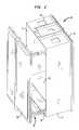
- FIG. 1is a left perspective view of a cabinet including the hinged tracking system of the present invention showing the door in a translated and rotated position;
- FIG. 2is a right perspective view of the cabinet of FIG. 1 showing the door in a translated position only;
- FIG. 3is a perspective view of the hinged tracking system in an extended position
- FIG. 4is a cross-sectional view of the hinged tracking system taken along line 4 — 4 of FIG. 3;
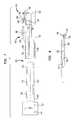
- FIG. 5is an exploded side view of a second embodiment of the hinged tracking system of the present invention.
- FIG. 6is an exploded top view of the second embodiment of the hinged tracking system
- FIG. 7is an exploded side view of a third embodiment of the hinged tracking system of the present invention.
- FIG. 8is a top view of a locking portion of the third embodiment of the hinged tracking system.
- the cabinet 10is preferably used to enclose electronics, for example, electronics used in the telecommunications industry, in a weather-tight manner.
- the cabinet 10includes a back wall 12 , a pair of side walls 14 , a top wall 16 and a bottom wall 18 .
- One or more shelves 20may be located within the cabinet 10 .
- Apertures 22may be located in any of the walls 12 , 14 , 16 , 18 of the cabinet 10 for allowing conductors or the like to pass therethrough.
- An upper mounting bracket 24is fixed to the top wall 16
- a lower mounting bracket 26is fixed to the bottom wall 18 for fastening the cabinet 10 to a suitable structure (not shown) such as a building wall.
- the approximate dimensions of the cabinet 10are 17 inches wide, 24 inches high, and 9 1 ⁇ 4 inches deep.
- a door 28is located on the front of the cabinet 10 .
- the door 28is attached to the cabinet 10 by a hinged tracking system 30 .
- the hinged tracking system 30allows the door 28 to translate rectilinearly away from the cabinet 10 , as well as rotate with respect to the cabinet 10 .
- the door 28translates at least 6 1 ⁇ 4 inches, and rotates 90 degrees, although any desired amount of translation and rotation may be utilized depending on the particular application of the cabinet 10 . For example, it may be desirable to allow the door 28 to rotate 180 degrees.
- the hinged tracking system 30includes a track member 32 , an intermediate member 34 , and a slide member 36 .
- the intermediate member 34is slidably received within the track member 32
- the slide member 36is slidably received within the intermediate member 34 .
- the track member 32includes a flat central portion 38 and a pair of opposing inwardly-curved edge portions 40 .
- a mounting plate 42may be attached to the flat portion 38 of the track member 32 , preferably near one end thereof
- the mounting plate 42contains a plurality of mounting holes 44 therein which receive fasteners (not shown) for attaching the track member 32 to the side wall 19 of the cabinet 10 .
- the track member 32may be directly attached to the side wall 14 of the cabinet 10 utilizing suitable fasteners, such as screws, rivets, or spot welds.
- the intermediate member 34includes a flat central portion 46 , a pair of opposing outwardly-curved edge portions 48 , and a pair of opposing inwardly-curved edge portions 50 .
- the outwardly-curved edge portions 48 of the intermediate member 34are positioned adjacent to the inwardly-curved edge portions 40 of the track member 32 .
- a plurality of balls 52are located between the outwardly-curved edge portions 48 of the intermediate member 34 and the inwardly-curved edge portions 40 of the track member 32 to allow the intermediate member 34 to roll along the track member 32 during extension and retraction of the intermediate member 34 .
- the slide member 36includes a flat central portion 54 , and a pair of opposing outwardly-curved edge portions 56 .
- the outwardly-curved edge portions 56 of the slide member 36are positioned adjacent to the inwardly-curved edge portions 50 of the intermediate member 34 .
- a plurality of balls 52are located between the outwardly-curved edge portions 56 of the slide member 36 and the inwardly-curved edge portions 50 of the intermediate member 34 to allow the slide member 36 to roll along the intermediate member 34 during extension and retraction of the slide member 36 .
- the hinge 58Located at one end of the slide member 36 is a hinge 58 .
- the hinge 58has a fixed leaf 60 pivotally attached to a rotating leaf 62 by a pivot pin 64 .
- the fixed leaf 60is fixed to the flat portion 54 of the slide member 36 by any suitable fastening method, such as screws, rivets, or spot welds.
- the door 28(see FIGS. 1 or 2 ) is attached to the rotating leaf 62 by any suitable fastening method, such as screws, rivets, or spot welds.
- the door 28may be moved linearly from the closed position to a spaced position, as shown in FIG. 2, and then pivoted from the spaced position to a spaced/rotated position, as shown in FIG. 1, whereby the cabinet 10 is open and the contents therein are easily accessible.
- the door 28may be pivoted from the closed position to a rotated position, and then moved linearly from the rotated position to a spaced/rotated position shown in FIG. 1 .
- the door 28may be moved in any combination of translation and rotation.
- the hinged tracking system 130 of the second embodimentdoes not include the intermediate member 34 as did the first embodiment. Instead, the second embodiment includes a track member 132 having a slide member 136 slidably mounted therein.
- the track member 132includes a flat central portion 138 and a pair of opposing side edge portions 140 which are curved around to form a hollow substantially tubular configuration.
- a mounting plate 142 having a plurality of mounting holes 144 thereinis formed as an enlarged extension of one end of the flat central portion 138 of the track member 132 for attaching the track member 132 to the cabinet 10 .
- the mounting plate 142may be attached to the flat portion 138 of the track member 132 , preferably near one end thereof, as described above with respect to the first embodiment.
- the slide member 136includes a flat central portion 154 , and a pair of opposing side edge portions 156 which are curved around and flattened. The slide member 136 slides along the interior of the track member 132 during extension and retraction of the slide member 136 .
- the track member 132 and the slide member 136each include stoppers which prevent overtravel of the slide member 136 with respect to the track member 132 , so that the slide member 136 does not inadvertently slide completely out of the track member 132 .
- a first stopper 166is located interiorly of the tubular configuration of the track member 132 near one end thereof, preferably on the curved portion.
- a second stopper 168is located on the exterior of the slide member 136 near one end thereof, preferably on the curved portion also.
- a hinge 158is located at one end of the slide member 136 , in the manner described above with respect to the first embodiment. However, the hinge 158 in the second embodiment is somewhat shorter than the hinge 158 in the first embodiment.
- the track member 132is fixed to the cabinet 10 , and the door 28 is attached to the hinge 158 . Translational and rotational operation of the door 28 is the same as described above with respect to the first embodiment, except that the stoppers 166 , 168 prevent overtravel of the slide member 136 with respect to the track member 132 , so that the slide member 136 does not inadvertently slide completely out of the track member 132 .
- the hinged tracking system 230 of the third embodimentdoes not include the intermediate member 34 as did the first embodiment Instead, the third embodiment includes a track member 232 and a slide member 236 as did the second embodiment However, unlike the second embodiment where the slide member 136 is sidably mounted within the track member 132 , in the third embodiment, the slide member 236 is slidably mounted around the track member 232 .
- the track member 232includes a flat central portion 238 and a pair of opposing side edge portions 240 which are curved around and flattened.
- a mounting plate 242 having a plurality of mounting holes 244 thereinmay be formed as an extension of the flat portion 238 of the track member 232 , as described above with respect to the first and second embodiments, for attaching the track member 232 to the cabinet 10 .
- the slide member 236includes a flat central portion 254 , and a pair of opposing side edge portions 256 which are curved around to fonn a hollow substantially tubular configuration.
- the slide member 236slides around the exterior of the track member 232 during extension and retraction of the slide member 236 .
- a hinge 258is located at one end of the slide member 236 , in the manner described above with respect to the second embodiment.
- the track member 232is fixed to the cabinet 10 , and the door 28 is attached to the hinge 258 .
- Translational and rotational operation of the door 28is the same as described above with respect to the first and second embodiments.
- the slide member 236includes a slide locking system 270 which allows the slide member 236 to be locked in a fully extended maximum position.
- the slide locking system 270includes a slide locking pin 272 movably attached to the slide member 236 .
- the slide locking pin 272is movable within an aperture 274 in the curved portion of the slide member 236 between an engaged position and a disengaged position.
- a leaf spring 276biases the slide locking pin 272 toward the engaged position.
- a slide locking indentation 278is provided in the curved portion of the track member 232 which defines the maximum allowable translation of the slide member 236 .
- the end of the slide locking pin 272slides along the surface of the curved portion of the track member 232 until the maximum allowable translation position is reached.
- the slide locking pin 272become aligned with the slide locking indentation 278 , and is moved thereinto by the biasing force provided by the leaf spring 276 .
- a knob 280is attached to the slide locking pin 272 which may be grasped by a user to move the slide locking pin 272 to a disengaged position against the biasing force provided by the leaf spring 276 , and the slide member 236 may then be slid along the track member 232 to a retracted position. Alterative, with the slide locking pin 272 in a disengaged position, the door 28 may be completely removed from the cabinet 10 by sliding the slide member 236 completely off of the track member 232 .
- the slide member 236further includes a hinge locking system 282 which allows the hinge 258 to be locked in a filly closed position or in a fully open position, which may be defined as a position rotated approximately 90 degrees from the closed position.
- the hinge locking system 282includes a hinge locking pin 284 movably attached to the slide member 236 .
- the hinge locking pin 284is movable within an aperture 286 in the curved portion of the slide member 236 between an engaged position and a disengaged position.
- a leaf spring 288biases the hinge locking pin 284 toward the engaged position.
- a stop member 290is pivotally mounted to the rotating leaf 262 of the hinge 258 , and is slidably mounted within the slide member 236 . As the rotating leaf 262 is rotated between the closed position and the open position, the stop member 290 slides back and forth along the slide member 236 .
- First and second hinge locking indentations 292 , 294are provided in the top portion of the stop member 290 which define the closed and the fully open positions of the hinge 258 .
- the end of the hinge locking pin 284slides along the surface of the top portion of the stop member 290 until the filly open position is reached.
- the hinge locking pin 284become aligned with the first hinge locking indentation 292 , and is moved thereinto by the biasing force provided by the leaf spring 288 .
- a knob 296is attached to the hinge locking pin 284 which may be grasped by a user to move the hinge locking pin 284 to a disengaged position against the biasing force provided by the leaf spring 288 , and the rotating leaf 262 of the hinge 258 may then be rotated toward the closed position. Once in the closed position, the hinge locking pin 284 becomes aligned with the second hinge locking indentation 294 , and is moved thereinto by the biasing force provided by the leaf spring 288 .
- locking systems 270 , 282 of the present inventionhave been described with reference to a third embodiment, it should be understood that these locking systems 270 , 282 can also be incorporated into the first and second embodiments.
Landscapes
- Engineering & Computer Science (AREA)
- Mechanical Engineering (AREA)
- Civil Engineering (AREA)
- Structural Engineering (AREA)
- Power Engineering (AREA)
- Hinges (AREA)
Abstract
Description
Claims (23)
Priority Applications (1)
| Application Number | Priority Date | Filing Date | Title |
|---|---|---|---|
| US09/181,868US6318824B1 (en) | 1998-10-29 | 1998-10-29 | Hinged tracking system |
Applications Claiming Priority (1)
| Application Number | Priority Date | Filing Date | Title |
|---|---|---|---|
| US09/181,868US6318824B1 (en) | 1998-10-29 | 1998-10-29 | Hinged tracking system |
Publications (1)
| Publication Number | Publication Date |
|---|---|
| US6318824B1true US6318824B1 (en) | 2001-11-20 |
Family
ID=22666146
Family Applications (1)
| Application Number | Title | Priority Date | Filing Date |
|---|---|---|---|
| US09/181,868Expired - LifetimeUS6318824B1 (en) | 1998-10-29 | 1998-10-29 | Hinged tracking system |
Country Status (1)
| Country | Link |
|---|---|
| US (1) | US6318824B1 (en) |
Cited By (64)
| Publication number | Priority date | Publication date | Assignee | Title |
|---|---|---|---|---|
| US20040080244A1 (en)* | 2002-10-28 | 2004-04-29 | Lowther Robert J. | Expandable server cabinet |
| US6841422B2 (en) | 1997-06-19 | 2005-01-11 | Micron Technology, Inc. | Plastic lead frames for semiconductor devices, packages including same, and methods of fabrication |
| FR2896946A1 (en)* | 2006-02-01 | 2007-08-03 | Legrand France | Closing part`s e.g. door, pivoting axle support e.g. hinge, for terminal box, has support clutching system that allows to mount support on notched support foot that is integrated to base of terminal box |
| US20100108683A1 (en)* | 2007-04-16 | 2010-05-06 | Roylan Developments Limited | Storage enclosures |
| US20100283367A1 (en)* | 2009-05-07 | 2010-11-11 | Whirlpool Corporation | Articulated hinges using non-circular gears |
| US20100283366A1 (en)* | 2009-05-07 | 2010-11-11 | Whirlpool Corporation | Method of routing utilities through an articulated hinge |
| US20110001410A1 (en)* | 2009-07-03 | 2011-01-06 | Wan-Lai Chen | Hinged slide rail with buffering function |
| GB2472243A (en)* | 2009-07-30 | 2011-02-02 | Usystems Limied | A cabinet door which slides outwardly in a horizontal plane |
| US20110150407A1 (en)* | 2009-12-18 | 2011-06-23 | Beamon Hubert B | Rotary Locking Apparatus for Fiber Optic Equipment Trays and Related Methods |
| US20110248611A1 (en)* | 2010-04-13 | 2011-10-13 | Whirlpool Corporation | Appliance cabinet and method of assembling same |
| US20120062092A1 (en)* | 2010-09-09 | 2012-03-15 | Yongki Jung | Guide rail attaching structure for sliding door and refrigerator having the same |
| US8433171B2 (en) | 2009-06-19 | 2013-04-30 | Corning Cable Systems Llc | High fiber optic cable packing density apparatus |
| US20130145547A1 (en)* | 2010-06-16 | 2013-06-13 | Wonderland Nurserygoods Company Limited | Baby Crib |
| US8538226B2 (en) | 2009-05-21 | 2013-09-17 | Corning Cable Systems Llc | Fiber optic equipment guides and rails configured with stopping position(s), and related equipment and methods |
| US8542973B2 (en) | 2010-04-23 | 2013-09-24 | Ccs Technology, Inc. | Fiber optic distribution device |
| US8593828B2 (en) | 2010-02-04 | 2013-11-26 | Corning Cable Systems Llc | Communications equipment housings, assemblies, and related alignment features and methods |
| US8660397B2 (en) | 2010-04-30 | 2014-02-25 | Corning Cable Systems Llc | Multi-layer module |
| US8662760B2 (en) | 2010-10-29 | 2014-03-04 | Corning Cable Systems Llc | Fiber optic connector employing optical fiber guide member |
| US8699838B2 (en) | 2009-05-14 | 2014-04-15 | Ccs Technology, Inc. | Fiber optic furcation module |
| US8705926B2 (en) | 2010-04-30 | 2014-04-22 | Corning Optical Communications LLC | Fiber optic housings having a removable top, and related components and methods |
| US8712206B2 (en) | 2009-06-19 | 2014-04-29 | Corning Cable Systems Llc | High-density fiber optic modules and module housings and related equipment |
| US8718436B2 (en) | 2010-08-30 | 2014-05-06 | Corning Cable Systems Llc | Methods, apparatuses for providing secure fiber optic connections |
| US8879881B2 (en) | 2010-04-30 | 2014-11-04 | Corning Cable Systems Llc | Rotatable routing guide and assembly |
| US8913866B2 (en) | 2010-03-26 | 2014-12-16 | Corning Cable Systems Llc | Movable adapter panel |
| US8953924B2 (en) | 2011-09-02 | 2015-02-10 | Corning Cable Systems Llc | Removable strain relief brackets for securing fiber optic cables and/or optical fibers to fiber optic equipment, and related assemblies and methods |
| US8965168B2 (en) | 2010-04-30 | 2015-02-24 | Corning Cable Systems Llc | Fiber management devices for fiber optic housings, and related components and methods |
| US8989547B2 (en) | 2011-06-30 | 2015-03-24 | Corning Cable Systems Llc | Fiber optic equipment assemblies employing non-U-width-sized housings and related methods |
| US8985862B2 (en) | 2013-02-28 | 2015-03-24 | Corning Cable Systems Llc | High-density multi-fiber adapter housings |
| US8995812B2 (en) | 2012-10-26 | 2015-03-31 | Ccs Technology, Inc. | Fiber optic management unit and fiber optic distribution device |
| US9008485B2 (en) | 2011-05-09 | 2015-04-14 | Corning Cable Systems Llc | Attachment mechanisms employed to attach a rear housing section to a fiber optic housing, and related assemblies and methods |
| US9020320B2 (en) | 2008-08-29 | 2015-04-28 | Corning Cable Systems Llc | High density and bandwidth fiber optic apparatuses and related equipment and methods |
| US9022814B2 (en) | 2010-04-16 | 2015-05-05 | Ccs Technology, Inc. | Sealing and strain relief device for data cables |
| US9038832B2 (en) | 2011-11-30 | 2015-05-26 | Corning Cable Systems Llc | Adapter panel support assembly |
| US9042702B2 (en) | 2012-09-18 | 2015-05-26 | Corning Cable Systems Llc | Platforms and systems for fiber optic cable attachment |
| US9059578B2 (en) | 2009-02-24 | 2015-06-16 | Ccs Technology, Inc. | Holding device for a cable or an assembly for use with a cable |
| US9075217B2 (en) | 2010-04-30 | 2015-07-07 | Corning Cable Systems Llc | Apparatuses and related components and methods for expanding capacity of fiber optic housings |
| US9116324B2 (en) | 2010-10-29 | 2015-08-25 | Corning Cable Systems Llc | Stacked fiber optic modules and fiber optic equipment configured to support stacked fiber optic modules |
| US9213161B2 (en) | 2010-11-05 | 2015-12-15 | Corning Cable Systems Llc | Fiber body holder and strain relief device |
| US9250409B2 (en) | 2012-07-02 | 2016-02-02 | Corning Cable Systems Llc | Fiber-optic-module trays and drawers for fiber-optic equipment |
| US9279951B2 (en) | 2010-10-27 | 2016-03-08 | Corning Cable Systems Llc | Fiber optic module for limited space applications having a partially sealed module sub-assembly |
| US20160264246A1 (en)* | 2015-03-13 | 2016-09-15 | The Boeing Company | Folding galley unit |
| US9519118B2 (en) | 2010-04-30 | 2016-12-13 | Corning Optical Communications LLC | Removable fiber management sections for fiber optic housings, and related components and methods |
| US9632270B2 (en) | 2010-04-30 | 2017-04-25 | Corning Optical Communications LLC | Fiber optic housings configured for tool-less assembly, and related components and methods |
| US9645317B2 (en) | 2011-02-02 | 2017-05-09 | Corning Optical Communications LLC | Optical backplane extension modules, and related assemblies suitable for establishing optical connections to information processing modules disposed in equipment racks |
| GB2545256A (en)* | 2015-12-11 | 2017-06-14 | Electrix Int Ltd | An electrical component enclosure with a hygienic hinge |
| US9720195B2 (en) | 2010-04-30 | 2017-08-01 | Corning Optical Communications LLC | Apparatuses and related components and methods for attachment and release of fiber optic housings to and from an equipment rack |
| WO2017151050A1 (en)* | 2016-03-04 | 2017-09-08 | Hans-Erik Johansson I Hagstad Ab | Lockable electronics cabinet |
| US20170350177A1 (en)* | 2015-02-26 | 2017-12-07 | Huawei Technologies Co., Ltd. | Door and Suspension Mechanism Assembly and An Assembly of An Elongated Housing and A Door and Suspension Mechanism Assembly |
| US9872420B1 (en)* | 2016-08-15 | 2018-01-16 | Rohde & Schwarz Gmbh & Co. Kg | Shielding box for providing high frequency electromagnetic shielding |
| CN108065646A (en)* | 2018-01-05 | 2018-05-25 | 广东东泰五金精密制造有限公司 | A kind of revolution open and close locking structure for furniture |
| CN108513474A (en)* | 2018-05-28 | 2018-09-07 | 新利同创(天津)电子设备有限公司 | A kind of switch board that cabinet door translation rotarily opens |
| US10094996B2 (en) | 2008-08-29 | 2018-10-09 | Corning Optical Communications, Llc | Independently translatable modules and fiber optic equipment trays in fiber optic equipment |
| US20180313122A1 (en)* | 2015-10-21 | 2018-11-01 | Faraday&Future Inc. | Door hinge mechanism for a vehicle |
| US20190208661A1 (en)* | 2016-05-24 | 2019-07-04 | Meidensha Corporation | Casing separation mechanism |
| US20190301218A1 (en)* | 2017-01-13 | 2019-10-03 | Julius Blum Gmbh | Guide system for furniture parts |
| US11089711B2 (en)* | 2017-05-19 | 2021-08-10 | Meidensha Corporation | Workbench and wiring duct |
| US11234512B2 (en)* | 2017-03-02 | 2022-02-01 | Hettich Holding Gmbh & Co. Ohg | Cupboard or household appliance and method for opening and closing a cupboard or household appliance |
| CN114268028A (en)* | 2021-12-24 | 2022-04-01 | 江西三龙电气有限公司 | Three-dimensionally distributed multi-element integrated power distribution cabinet |
| US11294136B2 (en) | 2008-08-29 | 2022-04-05 | Corning Optical Communications LLC | High density and bandwidth fiber optic apparatuses and related equipment and methods |
| CN114336355A (en)* | 2022-01-04 | 2022-04-12 | 冯剑茹 | A convenient power cabinet |
| US20220232725A1 (en)* | 2021-01-21 | 2022-07-21 | Dell Products L.P. | Mechanisms and methods for two-sided rack access |
| US20220408914A1 (en)* | 2021-06-25 | 2022-12-29 | Patrick J. Callahan | Storage system |
| IT202100024824A1 (en)* | 2021-09-28 | 2023-03-28 | Paolo Fornasari | SUPPORT, HANDLING AND CONCEALMENT SYSTEM FOR AT LEAST TWO DOORS |
| CN116786252A (en)* | 2023-07-24 | 2023-09-22 | 江苏省群飞机械制造有限公司 | Crusher with rapid feeding mechanism and using method thereof |
Citations (12)
| Publication number | Priority date | Publication date | Assignee | Title |
|---|---|---|---|---|
| GB191316749A (en)* | 1913-07-21 | 1913-11-06 | Gilbert Henry Pledge | Improvements in and connected with Show Cases, Wardrobes, Cupboards and the like. |
| GB546905A (en)* | 1942-01-21 | 1942-08-05 | Emil Kaufmann | Improved door for furniture, buildings and the like |
| FR1075079A (en)* | 1953-02-27 | 1954-10-12 | Cie Ind Des Telephones | Cabinet with re-entrant door |
| US2739024A (en)* | 1953-02-20 | 1956-03-20 | Elman Jerome | Storage cabinet construction |
| US3966273A (en)* | 1974-09-13 | 1976-06-29 | Hagen Magnus F | Synchronized and precision sequencing of ball retainer relationship to the inner and outer slide members |
| FR2469149A1 (en)* | 1979-11-15 | 1981-05-22 | France H K | Store container for keys - consists of frame open at front, containing vertical panels pivot mounted on top and bottom slide pieces |
| US4516813A (en)* | 1983-04-11 | 1985-05-14 | Grant Hardware Company | Cabinet door mounting mechanism |
| US4709972A (en)* | 1986-08-27 | 1987-12-01 | Eastman Kodak Company | Keyboard cabinet with sliding tray |
| US4945972A (en)* | 1988-08-31 | 1990-08-07 | Nec Home Electronics Ltd. | Containable door of folding type |
| US4974912A (en)* | 1989-04-05 | 1990-12-04 | Standard Precision, Inc. | Pocket door suspension system |
| US5169221A (en)* | 1990-09-04 | 1992-12-08 | General Devices Co., Inc. | Pivotable drawer slide mount with pivot controlling guide slot |
| US5775786A (en)* | 1997-02-05 | 1998-07-07 | Haworth, Inc. | Drawer slide |
- 1998
- 1998-10-29USUS09/181,868patent/US6318824B1/ennot_activeExpired - Lifetime
Patent Citations (12)
| Publication number | Priority date | Publication date | Assignee | Title |
|---|---|---|---|---|
| GB191316749A (en)* | 1913-07-21 | 1913-11-06 | Gilbert Henry Pledge | Improvements in and connected with Show Cases, Wardrobes, Cupboards and the like. |
| GB546905A (en)* | 1942-01-21 | 1942-08-05 | Emil Kaufmann | Improved door for furniture, buildings and the like |
| US2739024A (en)* | 1953-02-20 | 1956-03-20 | Elman Jerome | Storage cabinet construction |
| FR1075079A (en)* | 1953-02-27 | 1954-10-12 | Cie Ind Des Telephones | Cabinet with re-entrant door |
| US3966273A (en)* | 1974-09-13 | 1976-06-29 | Hagen Magnus F | Synchronized and precision sequencing of ball retainer relationship to the inner and outer slide members |
| FR2469149A1 (en)* | 1979-11-15 | 1981-05-22 | France H K | Store container for keys - consists of frame open at front, containing vertical panels pivot mounted on top and bottom slide pieces |
| US4516813A (en)* | 1983-04-11 | 1985-05-14 | Grant Hardware Company | Cabinet door mounting mechanism |
| US4709972A (en)* | 1986-08-27 | 1987-12-01 | Eastman Kodak Company | Keyboard cabinet with sliding tray |
| US4945972A (en)* | 1988-08-31 | 1990-08-07 | Nec Home Electronics Ltd. | Containable door of folding type |
| US4974912A (en)* | 1989-04-05 | 1990-12-04 | Standard Precision, Inc. | Pocket door suspension system |
| US5169221A (en)* | 1990-09-04 | 1992-12-08 | General Devices Co., Inc. | Pivotable drawer slide mount with pivot controlling guide slot |
| US5775786A (en)* | 1997-02-05 | 1998-07-07 | Haworth, Inc. | Drawer slide |
Cited By (107)
| Publication number | Priority date | Publication date | Assignee | Title |
|---|---|---|---|---|
| US6841422B2 (en) | 1997-06-19 | 2005-01-11 | Micron Technology, Inc. | Plastic lead frames for semiconductor devices, packages including same, and methods of fabrication |
| US20040080244A1 (en)* | 2002-10-28 | 2004-04-29 | Lowther Robert J. | Expandable server cabinet |
| FR2896946A1 (en)* | 2006-02-01 | 2007-08-03 | Legrand France | Closing part`s e.g. door, pivoting axle support e.g. hinge, for terminal box, has support clutching system that allows to mount support on notched support foot that is integrated to base of terminal box |
| US20100108683A1 (en)* | 2007-04-16 | 2010-05-06 | Roylan Developments Limited | Storage enclosures |
| US8511509B2 (en)* | 2007-04-16 | 2013-08-20 | Roylan Developments Limited | Storage enclosures |
| US9910236B2 (en) | 2008-08-29 | 2018-03-06 | Corning Optical Communications LLC | High density and bandwidth fiber optic apparatuses and related equipment and methods |
| US11754796B2 (en) | 2008-08-29 | 2023-09-12 | Corning Optical Communications LLC | Independently translatable modules and fiber optic equipment trays in fiber optic equipment |
| US10120153B2 (en) | 2008-08-29 | 2018-11-06 | Corning Optical Communications, Llc | Independently translatable modules and fiber optic equipment trays in fiber optic equipment |
| US10126514B2 (en) | 2008-08-29 | 2018-11-13 | Corning Optical Communications, Llc | Independently translatable modules and fiber optic equipment trays in fiber optic equipment |
| US10222570B2 (en) | 2008-08-29 | 2019-03-05 | Corning Optical Communications LLC | Independently translatable modules and fiber optic equipment trays in fiber optic equipment |
| US10416405B2 (en) | 2008-08-29 | 2019-09-17 | Corning Optical Communications LLC | Independently translatable modules and fiber optic equipment trays in fiber optic equipment |
| US10422971B2 (en) | 2008-08-29 | 2019-09-24 | Corning Optical Communicatinos LLC | High density and bandwidth fiber optic apparatuses and related equipment and methods |
| US10094996B2 (en) | 2008-08-29 | 2018-10-09 | Corning Optical Communications, Llc | Independently translatable modules and fiber optic equipment trays in fiber optic equipment |
| US10444456B2 (en) | 2008-08-29 | 2019-10-15 | Corning Optical Communications LLC | High density and bandwidth fiber optic apparatuses and related equipment and methods |
| US11609396B2 (en) | 2008-08-29 | 2023-03-21 | Corning Optical Communications LLC | High density and bandwidth fiber optic apparatuses and related equipment and methods |
| US11294135B2 (en) | 2008-08-29 | 2022-04-05 | Corning Optical Communications LLC | High density and bandwidth fiber optic apparatuses and related equipment and methods |
| US12072545B2 (en) | 2008-08-29 | 2024-08-27 | Corning Optical Communications LLC | High density and bandwidth fiber optic apparatuses and related equipment and methods |
| US10459184B2 (en) | 2008-08-29 | 2019-10-29 | Corning Optical Communications LLC | High density and bandwidth fiber optic apparatuses and related equipment and methods |
| US11294136B2 (en) | 2008-08-29 | 2022-04-05 | Corning Optical Communications LLC | High density and bandwidth fiber optic apparatuses and related equipment and methods |
| US11092767B2 (en) | 2008-08-29 | 2021-08-17 | Corning Optical Communications LLC | High density and bandwidth fiber optic apparatuses and related equipment and methods |
| US10564378B2 (en) | 2008-08-29 | 2020-02-18 | Corning Optical Communications LLC | High density and bandwidth fiber optic apparatuses and related equipment and methods |
| US10606014B2 (en) | 2008-08-29 | 2020-03-31 | Corning Optical Communications LLC | Independently translatable modules and fiber optic equipment trays in fiber optic equipment |
| US9020320B2 (en) | 2008-08-29 | 2015-04-28 | Corning Cable Systems Llc | High density and bandwidth fiber optic apparatuses and related equipment and methods |
| US11086089B2 (en) | 2008-08-29 | 2021-08-10 | Corning Optical Communications LLC | High density and bandwidth fiber optic apparatuses and related equipment and methods |
| US10852499B2 (en) | 2008-08-29 | 2020-12-01 | Corning Optical Communications LLC | High density and bandwidth fiber optic apparatuses and related equipment and methods |
| US9059578B2 (en) | 2009-02-24 | 2015-06-16 | Ccs Technology, Inc. | Holding device for a cable or an assembly for use with a cable |
| US8186781B2 (en) | 2009-05-07 | 2012-05-29 | Whirlpool Corporation | Articulated hinges using non-circular gears |
| US20100283367A1 (en)* | 2009-05-07 | 2010-11-11 | Whirlpool Corporation | Articulated hinges using non-circular gears |
| US8267492B2 (en) | 2009-05-07 | 2012-09-18 | Whirlpool Corporation | Method of routing utilities through an articulated hinge |
| US20100283366A1 (en)* | 2009-05-07 | 2010-11-11 | Whirlpool Corporation | Method of routing utilities through an articulated hinge |
| US8699838B2 (en) | 2009-05-14 | 2014-04-15 | Ccs Technology, Inc. | Fiber optic furcation module |
| US9075216B2 (en) | 2009-05-21 | 2015-07-07 | Corning Cable Systems Llc | Fiber optic housings configured to accommodate fiber optic modules/cassettes and fiber optic panels, and related components and methods |
| US8538226B2 (en) | 2009-05-21 | 2013-09-17 | Corning Cable Systems Llc | Fiber optic equipment guides and rails configured with stopping position(s), and related equipment and methods |
| US8433171B2 (en) | 2009-06-19 | 2013-04-30 | Corning Cable Systems Llc | High fiber optic cable packing density apparatus |
| US8712206B2 (en) | 2009-06-19 | 2014-04-29 | Corning Cable Systems Llc | High-density fiber optic modules and module housings and related equipment |
| US7987555B2 (en)* | 2009-07-03 | 2011-08-02 | Martas Precision Slide Co., Ltd. | Hinged slide rail with buffering function |
| US20110001410A1 (en)* | 2009-07-03 | 2011-01-06 | Wan-Lai Chen | Hinged slide rail with buffering function |
| GB2472243A (en)* | 2009-07-30 | 2011-02-02 | Usystems Limied | A cabinet door which slides outwardly in a horizontal plane |
| US20110150407A1 (en)* | 2009-12-18 | 2011-06-23 | Beamon Hubert B | Rotary Locking Apparatus for Fiber Optic Equipment Trays and Related Methods |
| US8625950B2 (en)* | 2009-12-18 | 2014-01-07 | Corning Cable Systems Llc | Rotary locking apparatus for fiber optic equipment trays and related methods |
| US8992099B2 (en) | 2010-02-04 | 2015-03-31 | Corning Cable Systems Llc | Optical interface cards, assemblies, and related methods, suited for installation and use in antenna system equipment |
| US8593828B2 (en) | 2010-02-04 | 2013-11-26 | Corning Cable Systems Llc | Communications equipment housings, assemblies, and related alignment features and methods |
| US8913866B2 (en) | 2010-03-26 | 2014-12-16 | Corning Cable Systems Llc | Movable adapter panel |
| US8215729B2 (en)* | 2010-04-13 | 2012-07-10 | Whirlpool Corporation | Appliance cabinet and method of assembling same |
| US20110248611A1 (en)* | 2010-04-13 | 2011-10-13 | Whirlpool Corporation | Appliance cabinet and method of assembling same |
| US20120217853A1 (en)* | 2010-04-13 | 2012-08-30 | Whirlpool Corporation | Appliance cabinet and method of assembling same |
| US8550577B2 (en)* | 2010-04-13 | 2013-10-08 | Whirlpool Corporation | Appliance cabinet and method of assembling same |
| US9022814B2 (en) | 2010-04-16 | 2015-05-05 | Ccs Technology, Inc. | Sealing and strain relief device for data cables |
| US8542973B2 (en) | 2010-04-23 | 2013-09-24 | Ccs Technology, Inc. | Fiber optic distribution device |
| US8705926B2 (en) | 2010-04-30 | 2014-04-22 | Corning Optical Communications LLC | Fiber optic housings having a removable top, and related components and methods |
| US9720195B2 (en) | 2010-04-30 | 2017-08-01 | Corning Optical Communications LLC | Apparatuses and related components and methods for attachment and release of fiber optic housings to and from an equipment rack |
| US9519118B2 (en) | 2010-04-30 | 2016-12-13 | Corning Optical Communications LLC | Removable fiber management sections for fiber optic housings, and related components and methods |
| US9632270B2 (en) | 2010-04-30 | 2017-04-25 | Corning Optical Communications LLC | Fiber optic housings configured for tool-less assembly, and related components and methods |
| US8660397B2 (en) | 2010-04-30 | 2014-02-25 | Corning Cable Systems Llc | Multi-layer module |
| US9075217B2 (en) | 2010-04-30 | 2015-07-07 | Corning Cable Systems Llc | Apparatuses and related components and methods for expanding capacity of fiber optic housings |
| US8879881B2 (en) | 2010-04-30 | 2014-11-04 | Corning Cable Systems Llc | Rotatable routing guide and assembly |
| US8965168B2 (en) | 2010-04-30 | 2015-02-24 | Corning Cable Systems Llc | Fiber management devices for fiber optic housings, and related components and methods |
| US20130145547A1 (en)* | 2010-06-16 | 2013-06-13 | Wonderland Nurserygoods Company Limited | Baby Crib |
| US8745780B2 (en)* | 2010-06-16 | 2014-06-10 | Wonderland Nurserygoods Company Limited | Baby crib |
| US8718436B2 (en) | 2010-08-30 | 2014-05-06 | Corning Cable Systems Llc | Methods, apparatuses for providing secure fiber optic connections |
| US8544970B2 (en)* | 2010-09-09 | 2013-10-01 | Lg Electronics Inc. | Guide rail attaching structure for sliding door and refrigerator having the same |
| US20120062092A1 (en)* | 2010-09-09 | 2012-03-15 | Yongki Jung | Guide rail attaching structure for sliding door and refrigerator having the same |
| US9279951B2 (en) | 2010-10-27 | 2016-03-08 | Corning Cable Systems Llc | Fiber optic module for limited space applications having a partially sealed module sub-assembly |
| US9116324B2 (en) | 2010-10-29 | 2015-08-25 | Corning Cable Systems Llc | Stacked fiber optic modules and fiber optic equipment configured to support stacked fiber optic modules |
| US8662760B2 (en) | 2010-10-29 | 2014-03-04 | Corning Cable Systems Llc | Fiber optic connector employing optical fiber guide member |
| US9213161B2 (en) | 2010-11-05 | 2015-12-15 | Corning Cable Systems Llc | Fiber body holder and strain relief device |
| US9645317B2 (en) | 2011-02-02 | 2017-05-09 | Corning Optical Communications LLC | Optical backplane extension modules, and related assemblies suitable for establishing optical connections to information processing modules disposed in equipment racks |
| US10481335B2 (en) | 2011-02-02 | 2019-11-19 | Corning Optical Communications, Llc | Dense shuttered fiber optic connectors and assemblies suitable for establishing optical connections for optical backplanes in equipment racks |
| US9008485B2 (en) | 2011-05-09 | 2015-04-14 | Corning Cable Systems Llc | Attachment mechanisms employed to attach a rear housing section to a fiber optic housing, and related assemblies and methods |
| US8989547B2 (en) | 2011-06-30 | 2015-03-24 | Corning Cable Systems Llc | Fiber optic equipment assemblies employing non-U-width-sized housings and related methods |
| US8953924B2 (en) | 2011-09-02 | 2015-02-10 | Corning Cable Systems Llc | Removable strain relief brackets for securing fiber optic cables and/or optical fibers to fiber optic equipment, and related assemblies and methods |
| US9038832B2 (en) | 2011-11-30 | 2015-05-26 | Corning Cable Systems Llc | Adapter panel support assembly |
| US9250409B2 (en) | 2012-07-02 | 2016-02-02 | Corning Cable Systems Llc | Fiber-optic-module trays and drawers for fiber-optic equipment |
| US9042702B2 (en) | 2012-09-18 | 2015-05-26 | Corning Cable Systems Llc | Platforms and systems for fiber optic cable attachment |
| US8995812B2 (en) | 2012-10-26 | 2015-03-31 | Ccs Technology, Inc. | Fiber optic management unit and fiber optic distribution device |
| US8985862B2 (en) | 2013-02-28 | 2015-03-24 | Corning Cable Systems Llc | High-density multi-fiber adapter housings |
| US20170350177A1 (en)* | 2015-02-26 | 2017-12-07 | Huawei Technologies Co., Ltd. | Door and Suspension Mechanism Assembly and An Assembly of An Elongated Housing and A Door and Suspension Mechanism Assembly |
| US10526831B2 (en)* | 2015-02-26 | 2020-01-07 | Huawei Technologies Co., Ltd. | Door and suspension mechanism assembly and an assembly of an elongated housing and a door and suspension mechanism assembly |
| US10953986B2 (en)* | 2015-03-13 | 2021-03-23 | The Boeing Company | Folding galley unit |
| US9802704B2 (en)* | 2015-03-13 | 2017-10-31 | The Boeing Company | Folding galley unit |
| US20160264246A1 (en)* | 2015-03-13 | 2016-09-15 | The Boeing Company | Folding galley unit |
| US20180313122A1 (en)* | 2015-10-21 | 2018-11-01 | Faraday&Future Inc. | Door hinge mechanism for a vehicle |
| US11118387B2 (en)* | 2015-10-21 | 2021-09-14 | Faraday & Future Inc. | Door hinge mechanism for a vehicle |
| GB2545256B (en)* | 2015-12-11 | 2019-01-09 | Electrix International Ltd | An electrical component enclosure with a hygienic hinge |
| US10034394B2 (en)* | 2015-12-11 | 2018-07-24 | Electrix International Ltd. | Electrical component enclosure with a hygienic hinge |
| GB2545256A (en)* | 2015-12-11 | 2017-06-14 | Electrix Int Ltd | An electrical component enclosure with a hygienic hinge |
| US20200296846A1 (en)* | 2016-03-04 | 2020-09-17 | Hans-Erik Johansson I Hagstad Ab | Lockable Electronics Cabinet |
| WO2017151050A1 (en)* | 2016-03-04 | 2017-09-08 | Hans-Erik Johansson I Hagstad Ab | Lockable electronics cabinet |
| EP3424285B1 (en)* | 2016-03-04 | 2022-10-26 | Hans-Erik Johansson I Hagstad AB | Lockable electronics cabinet |
| US10617030B2 (en)* | 2016-05-24 | 2020-04-07 | Meidensha Corporation | Casing separation mechanism |
| US20190208661A1 (en)* | 2016-05-24 | 2019-07-04 | Meidensha Corporation | Casing separation mechanism |
| US9872420B1 (en)* | 2016-08-15 | 2018-01-16 | Rohde & Schwarz Gmbh & Co. Kg | Shielding box for providing high frequency electromagnetic shielding |
| US11008791B2 (en)* | 2017-01-13 | 2021-05-18 | Julius Blum Gmbh | Guide system for furniture parts |
| US20190301218A1 (en)* | 2017-01-13 | 2019-10-03 | Julius Blum Gmbh | Guide system for furniture parts |
| US11234512B2 (en)* | 2017-03-02 | 2022-02-01 | Hettich Holding Gmbh & Co. Ohg | Cupboard or household appliance and method for opening and closing a cupboard or household appliance |
| US11089711B2 (en)* | 2017-05-19 | 2021-08-10 | Meidensha Corporation | Workbench and wiring duct |
| CN108065646A (en)* | 2018-01-05 | 2018-05-25 | 广东东泰五金精密制造有限公司 | A kind of revolution open and close locking structure for furniture |
| CN108513474B (en)* | 2018-05-28 | 2024-04-02 | 新利同创(天津)电子设备有限公司 | Cabinet door translation rotation opening control cabinet |
| CN108513474A (en)* | 2018-05-28 | 2018-09-07 | 新利同创(天津)电子设备有限公司 | A kind of switch board that cabinet door translation rotarily opens |
| US20220232725A1 (en)* | 2021-01-21 | 2022-07-21 | Dell Products L.P. | Mechanisms and methods for two-sided rack access |
| US11985785B2 (en)* | 2021-01-21 | 2024-05-14 | Dell Products L.P. | Mechanisms and methods for two-sided rack access |
| US20220408914A1 (en)* | 2021-06-25 | 2022-12-29 | Patrick J. Callahan | Storage system |
| US12369710B2 (en)* | 2021-06-25 | 2025-07-29 | Patrick J. Callahan | Storage system |
| IT202100024824A1 (en)* | 2021-09-28 | 2023-03-28 | Paolo Fornasari | SUPPORT, HANDLING AND CONCEALMENT SYSTEM FOR AT LEAST TWO DOORS |
| CN114268028A (en)* | 2021-12-24 | 2022-04-01 | 江西三龙电气有限公司 | Three-dimensionally distributed multi-element integrated power distribution cabinet |
| CN114336355A (en)* | 2022-01-04 | 2022-04-12 | 冯剑茹 | A convenient power cabinet |
| CN116786252A (en)* | 2023-07-24 | 2023-09-22 | 江苏省群飞机械制造有限公司 | Crusher with rapid feeding mechanism and using method thereof |
Similar Documents
| Publication | Publication Date | Title |
|---|---|---|
| US6318824B1 (en) | Hinged tracking system | |
| US6814244B1 (en) | Ramped latch closure system | |
| EP1704294B1 (en) | Rack-mounted door assembly | |
| US8250993B2 (en) | Laptop computer storage assembly for a work surface | |
| US5634701A (en) | Multi-drawer cabinet having a drawer lock-out mechanism | |
| US8235475B2 (en) | Anti-tip interlocking linkage mechanism for vertical cabinets | |
| US5871265A (en) | Two-way slide | |
| US7708357B2 (en) | Automatic locking apparatus used in guide rail for drawer | |
| US7959242B2 (en) | Pocket door cabinet and slide assembly | |
| CA2495387C (en) | Anti-tip interlocking linkage mechanism for vertical cabinets | |
| US6481586B1 (en) | Reversible shelving unit | |
| US20060289530A1 (en) | Hideaway oven door | |
| US4425013A (en) | Apparatus for locking cabinet drawers | |
| US7001001B1 (en) | Cabinet | |
| US4959582A (en) | Video storage cabinet | |
| US5368377A (en) | Flip-top computer workstation | |
| US8147008B2 (en) | Interlock system for multi-door enclosures | |
| US6966618B2 (en) | Furniture unit using dual slider mechanism | |
| US4662690A (en) | Filing cabinet with pivotal drawer | |
| US20040128915A1 (en) | Door for automated machine | |
| US4726637A (en) | Door support devices for cupboards | |
| US20200389989A1 (en) | Lay-flat lid with hidden dual hinge | |
| KR101963432B1 (en) | Lower roller apparatus of sliding door | |
| CN211459285U (en) | Door lock device for cabinet door | |
| DE10056950C1 (en) | Keyboard mounting device for switch cabinet plug-in frame has keyboard pivoted through 90 degrees between operating position and stowed position |
Legal Events
| Date | Code | Title | Description |
|---|---|---|---|
| AS | Assignment | Owner name:LUCENT TECHNOLOGIES INC., NEW JERSEY Free format text:ASSIGNMENT OF ASSIGNORS INTEREST;ASSIGNORS:LAGROTTA, RICHARD THOMAS;ORELLANA, MANUEL G.;REEL/FRAME:009566/0115 Effective date:19981026 | |
| STCF | Information on status: patent grant | Free format text:PATENTED CASE | |
| FPAY | Fee payment | Year of fee payment:4 | |
| FEPP | Fee payment procedure | Free format text:PAYOR NUMBER ASSIGNED (ORIGINAL EVENT CODE: ASPN); ENTITY STATUS OF PATENT OWNER: LARGE ENTITY | |
| FPAY | Fee payment | Year of fee payment:8 | |
| FPAY | Fee payment | Year of fee payment:12 | |
| AS | Assignment | Owner name:OMEGA CREDIT OPPORTUNITIES MASTER FUND, LP, NEW YORK Free format text:SECURITY INTEREST;ASSIGNOR:WSOU INVESTMENTS, LLC;REEL/FRAME:043966/0574 Effective date:20170822 Owner name:OMEGA CREDIT OPPORTUNITIES MASTER FUND, LP, NEW YO Free format text:SECURITY INTEREST;ASSIGNOR:WSOU INVESTMENTS, LLC;REEL/FRAME:043966/0574 Effective date:20170822 | |
| AS | Assignment | Owner name:WSOU INVESTMENTS, LLC, CALIFORNIA Free format text:ASSIGNMENT OF ASSIGNORS INTEREST;ASSIGNOR:ALCATEL LUCENT;REEL/FRAME:044000/0053 Effective date:20170722 | |
| AS | Assignment | Owner name:WSOU INVESTMENTS, LLC, CALIFORNIA Free format text:RELEASE BY SECURED PARTY;ASSIGNOR:OCO OPPORTUNITIES MASTER FUND, L.P. (F/K/A OMEGA CREDIT OPPORTUNITIES MASTER FUND LP;REEL/FRAME:049246/0405 Effective date:20190516 | |
| AS | Assignment | Owner name:OT WSOU TERRIER HOLDINGS, LLC, CALIFORNIA Free format text:SECURITY INTEREST;ASSIGNOR:WSOU INVESTMENTS, LLC;REEL/FRAME:056990/0081 Effective date:20210528 |