US6318525B1 - Shock absorber with improved damping - Google Patents
Shock absorber with improved dampingDownload PDFInfo
- Publication number
- US6318525B1 US6318525B1US09/306,899US30689999AUS6318525B1US 6318525 B1US6318525 B1US 6318525B1US 30689999 AUS30689999 AUS 30689999AUS 6318525 B1US6318525 B1US 6318525B1
- Authority
- US
- United States
- Prior art keywords
- shock absorber
- flow
- damping
- absorber according
- damping fluid
- Prior art date
- Legal status (The legal status is an assumption and is not a legal conclusion. Google has not performed a legal analysis and makes no representation as to the accuracy of the status listed.)
- Expired - Lifetime
Links
- 238000013016dampingMethods0.000titleclaimsabstractdescription66
- 230000035939shockEffects0.000titleclaimsabstractdescription63
- 239000006096absorbing agentSubstances0.000titleclaimsabstractdescription61
- 239000012530fluidSubstances0.000claimsabstractdescription57
- 230000006835compressionEffects0.000claimsabstractdescription40
- 238000007906compressionMethods0.000claimsabstractdescription40
- 239000007788liquidSubstances0.000claimsabstractdescription17
- 238000013017mechanical dampingMethods0.000claimsdescription2
- 238000006243chemical reactionMethods0.000abstractdescription3
- 239000000725suspensionSubstances0.000description21
- FGSSJBZUWRJOHA-UHFFFAOYSA-N1-[3-(dimethylamino)propyl]pyrrole-2,5-dione;styreneChemical compoundC=CC1=CC=CC=C1.CN(C)CCCN1C(=O)C=CC1=OFGSSJBZUWRJOHA-UHFFFAOYSA-N0.000description19
- 239000000463materialSubstances0.000description4
- 238000000034methodMethods0.000description4
- 230000003247decreasing effectEffects0.000description3
- 230000007246mechanismEffects0.000description3
- POIUWJQBRNEFGX-XAMSXPGMSA-NcathelicidinChemical compoundC([C@@H](C(=O)N[C@@H](CCCNC(N)=N)C(=O)N[C@@H](CCCCN)C(=O)N[C@@H](CO)C(=O)N[C@@H](CCCCN)C(=O)N[C@@H](CCC(O)=O)C(=O)N[C@@H](CCCCN)C(=O)N[C@@H]([C@@H](C)CC)C(=O)NCC(=O)N[C@@H](CCCCN)C(=O)N[C@@H](CCC(O)=O)C(=O)N[C@@H](CC=1C=CC=CC=1)C(=O)N[C@@H](CCCCN)C(=O)N[C@@H](CCCNC(N)=N)C(=O)N[C@@H]([C@@H](C)CC)C(=O)N[C@@H](C(C)C)C(=O)N[C@@H](CCC(N)=O)C(=O)N[C@@H](CCCNC(N)=N)C(=O)N[C@@H]([C@@H](C)CC)C(=O)N[C@@H](CCCCN)C(=O)N[C@@H](CC(O)=O)C(=O)N[C@@H](CC=1C=CC=CC=1)C(=O)N[C@@H](CC(C)C)C(=O)N[C@@H](CCCNC(N)=N)C(=O)N[C@@H](CC(N)=O)C(=O)N[C@@H](CC(C)C)C(=O)N[C@@H](C(C)C)C(=O)N1[C@@H](CCC1)C(=O)N[C@@H](CCCNC(N)=N)C(=O)N[C@@H]([C@@H](C)O)C(=O)N[C@@H](CCC(O)=O)C(=O)N[C@@H](CO)C(O)=O)NC(=O)[C@H](CC=1C=CC=CC=1)NC(=O)[C@H](CC(O)=O)NC(=O)CNC(=O)[C@H](CC(C)C)NC(=O)[C@@H](N)CC(C)C)C1=CC=CC=C1POIUWJQBRNEFGX-XAMSXPGMSA-N0.000description2
- 230000008030eliminationEffects0.000description2
- 238000003379elimination reactionMethods0.000description2
- 230000000284resting effectEffects0.000description2
- 229910000838Al alloyInorganic materials0.000description1
- 230000009471actionEffects0.000description1
- 239000000853adhesiveSubstances0.000description1
- 230000001070adhesive effectEffects0.000description1
- 230000000712assemblyEffects0.000description1
- 238000000429assemblyMethods0.000description1
- 230000015572biosynthetic processEffects0.000description1
- 230000000903blocking effectEffects0.000description1
- 229910002804graphiteInorganic materials0.000description1
- 239000010439graphiteSubstances0.000description1
- 230000006872improvementEffects0.000description1
- 238000004519manufacturing processMethods0.000description1
- 230000004048modificationEffects0.000description1
- 238000012986modificationMethods0.000description1
- 230000008520organizationEffects0.000description1
- 230000009467reductionEffects0.000description1
- 230000004044responseEffects0.000description1
- 239000011435rockSubstances0.000description1
- 238000000926separation methodMethods0.000description1
Images


Classifications
- B—PERFORMING OPERATIONS; TRANSPORTING
- B60—VEHICLES IN GENERAL
- B60G—VEHICLE SUSPENSION ARRANGEMENTS
- B60G17/00—Resilient suspensions having means for adjusting the spring or vibration-damper characteristics, for regulating the distance between a supporting surface and a sprung part of vehicle or for locking suspension during use to meet varying vehicular or surface conditions, e.g. due to speed or load
- B60G17/02—Spring characteristics, e.g. mechanical springs and mechanical adjusting means
- B60G17/027—Mechanical springs regulated by fluid means
- B60G17/0272—Mechanical springs regulated by fluid means the mechanical spring being a coil spring
- B—PERFORMING OPERATIONS; TRANSPORTING
- B60—VEHICLES IN GENERAL
- B60G—VEHICLE SUSPENSION ARRANGEMENTS
- B60G15/00—Resilient suspensions characterised by arrangement, location or type of combined spring and vibration damper, e.g. telescopic type
- B60G15/02—Resilient suspensions characterised by arrangement, location or type of combined spring and vibration damper, e.g. telescopic type having mechanical spring
- B60G15/06—Resilient suspensions characterised by arrangement, location or type of combined spring and vibration damper, e.g. telescopic type having mechanical spring and fluid damper
- B60G15/062—Resilient suspensions characterised by arrangement, location or type of combined spring and vibration damper, e.g. telescopic type having mechanical spring and fluid damper the spring being arranged around the damper
- B60G15/063—Resilient suspensions characterised by arrangement, location or type of combined spring and vibration damper, e.g. telescopic type having mechanical spring and fluid damper the spring being arranged around the damper characterised by the mounting of the spring on the damper
- F—MECHANICAL ENGINEERING; LIGHTING; HEATING; WEAPONS; BLASTING
- F16—ENGINEERING ELEMENTS AND UNITS; GENERAL MEASURES FOR PRODUCING AND MAINTAINING EFFECTIVE FUNCTIONING OF MACHINES OR INSTALLATIONS; THERMAL INSULATION IN GENERAL
- F16F—SPRINGS; SHOCK-ABSORBERS; MEANS FOR DAMPING VIBRATION
- F16F9/00—Springs, vibration-dampers, shock-absorbers, or similarly-constructed movement-dampers using a fluid or the equivalent as damping medium
- F16F9/06—Springs, vibration-dampers, shock-absorbers, or similarly-constructed movement-dampers using a fluid or the equivalent as damping medium using both gas and liquid
- F16F9/08—Springs, vibration-dampers, shock-absorbers, or similarly-constructed movement-dampers using a fluid or the equivalent as damping medium using both gas and liquid where gas is in a chamber with a flexible wall
- F16F9/096—Springs, vibration-dampers, shock-absorbers, or similarly-constructed movement-dampers using a fluid or the equivalent as damping medium using both gas and liquid where gas is in a chamber with a flexible wall comprising a hydropneumatic accumulator of the membrane type provided on the upper or the lower end of a damper or separately from or laterally on the damper
- F—MECHANICAL ENGINEERING; LIGHTING; HEATING; WEAPONS; BLASTING
- F16—ENGINEERING ELEMENTS AND UNITS; GENERAL MEASURES FOR PRODUCING AND MAINTAINING EFFECTIVE FUNCTIONING OF MACHINES OR INSTALLATIONS; THERMAL INSULATION IN GENERAL
- F16F—SPRINGS; SHOCK-ABSORBERS; MEANS FOR DAMPING VIBRATION
- F16F9/00—Springs, vibration-dampers, shock-absorbers, or similarly-constructed movement-dampers using a fluid or the equivalent as damping medium
- F16F9/32—Details
- F16F9/34—Special valve constructions; Shape or construction of throttling passages
- F—MECHANICAL ENGINEERING; LIGHTING; HEATING; WEAPONS; BLASTING
- F16—ENGINEERING ELEMENTS AND UNITS; GENERAL MEASURES FOR PRODUCING AND MAINTAINING EFFECTIVE FUNCTIONING OF MACHINES OR INSTALLATIONS; THERMAL INSULATION IN GENERAL
- F16F—SPRINGS; SHOCK-ABSORBERS; MEANS FOR DAMPING VIBRATION
- F16F9/00—Springs, vibration-dampers, shock-absorbers, or similarly-constructed movement-dampers using a fluid or the equivalent as damping medium
- F16F9/32—Details
- F16F9/44—Means on or in the damper for manual or non-automatic adjustment; such means combined with temperature correction
- B—PERFORMING OPERATIONS; TRANSPORTING
- B60—VEHICLES IN GENERAL
- B60G—VEHICLE SUSPENSION ARRANGEMENTS
- B60G2202/00—Indexing codes relating to the type of spring, damper or actuator
- B60G2202/10—Type of spring
- B60G2202/15—Fluid spring
- B60G2202/154—Fluid spring with an accumulator
- B—PERFORMING OPERATIONS; TRANSPORTING
- B60—VEHICLES IN GENERAL
- B60G—VEHICLE SUSPENSION ARRANGEMENTS
- B60G2202/00—Indexing codes relating to the type of spring, damper or actuator
- B60G2202/30—Spring/Damper and/or actuator Units
- B60G2202/31—Spring/Damper and/or actuator Units with the spring arranged around the damper, e.g. MacPherson strut
- B60G2202/312—The spring being a wound spring
- B—PERFORMING OPERATIONS; TRANSPORTING
- B60—VEHICLES IN GENERAL
- B60G—VEHICLE SUSPENSION ARRANGEMENTS
- B60G2204/00—Indexing codes related to suspensions per se or to auxiliary parts
- B60G2204/10—Mounting of suspension elements
- B60G2204/12—Mounting of springs or dampers
- B60G2204/124—Mounting of coil springs
- B60G2204/1242—Mounting of coil springs on a damper, e.g. MacPerson strut
- B—PERFORMING OPERATIONS; TRANSPORTING
- B60—VEHICLES IN GENERAL
- B60G—VEHICLE SUSPENSION ARRANGEMENTS
- B60G2500/00—Indexing codes relating to the regulated action or device
- B60G2500/20—Spring action or springs
Definitions
- the present inventionrelates generally to motorcycles and mountain bikes, and more particularly to suspension fork assemblies for use with the same.
- the present inventionprovides an apparatus and method for an improved shock absorber having increased damping, with this improved shock absorber providing a suspension with greatly improved stability and damping for a much more stable ride over rough terrain.
- the present inventionhas particular application to motorcycles commonly referred to as “dirt bikes” or mountain bike which are typically ridden over rough terrain and/or on steep uphill or downhill slopes.
- shock absorbing suspension systemsinclude a rigid rod (or inner tube), which is slidable within a rigid sleeve (or outer tube) and a biasing member which can operate pneumatically, hydraulically, elastomerically or with metallic springs, positioned within the rigid sleeve to achieve the “shock-absorbing” action.
- the biasing memberextends the fork rods relative to the sleeves, and as obstacles are encountered by the front or rear wheel, the biasing members of the fork's rigid sleeves collapse as the slidable rods are compressed in the sleeves, thereby absorbing the severe jolt.
- the sliding rodmay have a slight degree of rotatability within the sleeve.
- the forcesare substantially in the same axis as the suspension system, and the slidable rods are typically displaced uniformly.
- the forcesare not in the same axis as the suspension such that torsional and lateral stresses are created, and typically one of the rods is compressed or displaced into the corresponding sleeve more so than the opposite rod.
- the slidable rodhas a slight degree of rotatability within the sleeve, high stresses are created at the dropout-to-axle connection when lateral and torsional forces are applied to the wheel in contact with the ground, such as in cornering.
- One new design to increase the strength and rigidity at the wheel axlecomprises an enlarged wheel hub and axle (the axle being approximately 20 mm in diameter). While uniform compressions relieve stress on the wheel, fork, steering tube, and steering handle, unbalanced compressions, such as from cornering and maneuvering, the stresses on the wheel axle remain high. Therefore, increased rigidity and strength in the wheel axle is highly desirable for off-road motorcycles.
- Such a novel designin discussed in co-pending application Ser. No. 09/189,448, which is herein incorporated by reference. However, there remains a need to provide a suspension system which will reduce compression forces incurred during ordinary use of the motorcycle.
- lighter motorcycleis more desirable because it takes less force to power and maneuver.
- manufacturers of high-end performance bikes and their componentsare continuously upgrading them to decrease the overall weight. This has typically been accomplished in at least three ways. One is to use lighter materials such as aluminum alloys and carbon-graphite components. Another is to decrease the overall number of components that comprise the bicycle or motorcycle. Yet another is to decrease the thickness of the components used without sacrificing their strength.
- a front fork suspension systemincludes a crown which allows attachment of the central steering tube and a pair of parallel fork legs which each comprise an outer rigid sleeve and inner rigid rod which are slidably engaged with each other.
- the crownis connected to the fork legs via an adhesive or some form of mechanical connection (i.e., screws).
- the crownis provided with three openings wherein the outer two openings has slits near each of the outer ends.
- the center openingreceives the steerer tube, usually press fit into this opening.
- the outer two openingreceive the upper ends of the parallel fork legs, usually the upper ends of the inner rigid rods. Then, screw(s) or some other threaded fastening device(s) is employed to close or clamp the crown openings onto the upper ends of the inner rigid rods to form a tightly secured attachment.
- this mechanical means for attaching the fork legs to the crownhas several disadvantages, some of which include increased overall weight of the forks, increased number of stress points as well as increased stresses at these points, decreased overall strength and stability, etc.
- the invention of the '998 applicationhas overcome these shortcomings through a novel method of manufacturing the crown and legs as a single component.
- This “monolithic” crown/fork designresults in an overall lighter fork due to the elimination of extra components, increased strength and stability due to the elimination of high stress locations as well as a reduction in the stresses created at the interface of multiple components.
- a brake archis typically mounted on the upper portion of the lower fork legs via screws or other threaded fastening devices, one on each rod, while the brake arch has receptacles for mounting brake calipers.
- an upside down (or inverted) forkthe outer rigid sleeves and inner rigid rods are reversed. More specifically, the crown is connected to the outer rigid sleeves rather than to the inner rigid rods as previously described. This inverted design provides greater strength and stability at the crown/fork leg interface.
- Typical disc brake systemsare mounted on one of the dropouts at the wheel axle for maximum performance.
- the disc brakescomprise a separately mounted caliper containing the brake pads which, when in the closed position (i.e., pressed together), provide a high degree of frictional force to slow the wheel to a stop. It is therefore appreciated that the present invention can be used with motorcycles having either a conventional brake arch design or a conventional disc brake system.
- the present inventionrelates generally to suspension systems for bicycles or motorcycles.
- the present inventionprovides an adjustable shock absorber comprising a second damping mechanism to receive fluid from the main strut(s) to provide an enhanced damping of the shock absorber system in the compression phase.
- SDMsecondary damping mechanism
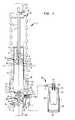
- FIG. 1shows an overall front plan view of a preferred embodiment of the apparatus for providing improved damping in a suspension system according to the present invention
- FIG. 1 ashows an overall front plan view of a preferred embodiment of the apparatus for providing improved damping in a suspension system according to the present invention in the expansion phase;
- FIG. 1 bshows an overall front plan view of a preferred embodiment of the apparatus for providing improved damping in a suspension system according to the present invention in the compression phase;
- FIG. 2shows an enlarged front plan view of the region of the apparatus for providing improved damping in a suspension system shown in FIG. 1 above line A—A;
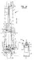
- FIG. 3shows an enlarged front plan view of the region of the apparatus for providing improved damping in a suspension system shown in FIG. 1 below line A—A;
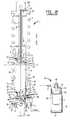
- FIG. 4shows an enlarged front plan view of the secondary damping means shown in FIG. 1;
- FIG. 5shows a front plan view of an alternate embodiment of the apparatus for providing improved damping in a suspension system according to the invention without the use of the external damping means.
- the present inventionrelates generally to motorcycles, but may be applied wherever suspension systems are used. Specifically, the present invention provides an apparatus and method for improved damping in suspension systems. Reference is herein made to the figures, wherein the numerals representing particular parts are consistently used throughout the figures and accompanying discussion.
- FIGS. 1, 1 a & 1 bshown is an overall front plan view of a preferred embodiment of the apparatus for providing improved damping in a suspension system according to the present invention, including strut 1 and secondary damping means 10 .
- FIGS. 1, 1 a & 1 bshow secondary damping means 10 attached to strut 1 via tube 3 .
- fluid from the internal cavities of strut 1flows through tube 3 into secondary damping means 10 .
- fluid from secondary damping means 10flows through tube 3 into the internal cavities of strut 1 .
- secondary damping means 10provides added damping to existing damping mechanisms within strut 1 , which are described in detail below.
- the strut 1 of the shock absorberis equipped in the lower part with a connecting appendage 101 (i.e., for the formation of a stem of a fork for a motorcycle, for the fastening to the axis of the rear wheel of the motorbike, etc.).
- strut 1may be equipped with additional appendages (not shown) for the support of a disc brake caliper or other conventional bicycle or motorcycle component.
- the upper part of strut 1(See FIG. 2) comprises connecting appendage 102 for attaching strut 1 on its upper end to the motorcycle frame below the seat area. Directly below the connecting appendage 102 is attached a truing cap 16 .
- the truing cap 16supports the upper end of the helical coil spring 4 which provides the mechanical damping of the strut.
- the piston 5At the center of the connecting appendage 102 is attached the piston 5 .
- a shaft 6At the center of the piston is a shaft 6 integral with barrel 14 .
- Free space 44 ′is intersected by a hole 35 ′ that extends from the wall of connecting appendage 102 to the lower edge of the free space 44 ′.
- a manual shaft adjustment 36 ′Within the hole 35 ′ is a manual shaft adjustment 36 ′ which moves laterally.
- a channel 40 ′Perpendicular to the hole 35 ′, from the bottom of connecting appendage 102 there is a channel 40 ′ which is internally threaded at the base.
- a spring loaded pin 39 ′which is externally threaded, is screwed into channel 40 ′. With the shaft adjustment 36 ′ in place, the spring loaded pin 39 ′ limits the movement of the shaft adjustment 36 ′ to the length of the counterbore 72 ′.
- the free space 44 ′is at the center of base 20 , and has a silo shaped recess 71 ′ opposite of the shaft adjustment 36 ′, which is designed to accommodate the shaft adjustment 36 ′ at full extension.
- the movement of the shaft 6is limited by the shaft adjustment 36 ′. Due to the taper 73 ′ in the shaft adjustment 36 ′, when the shaft adjustment is moved inward the shaft 6 is forced downward. The shaft 6 then restricts flow through the center hole 105 , of the piston flow damper 12 and may even stop flow entirely.
- the strut base 20is tapered in three levels being most narrow towards the bottom where the connecting appendage 101 is located and widest at the upper most portion where it accepts the strut barrel 14 .
- base 20Immediately above the connecting appendage 101 base 20 has a cylindrically shaped free space 44 at its center. Free space 44 is intersected by a hole 35 that extends form the wall of base 20 to the lower end of the free space 44 .
- a manual plug adjustment 36which moves laterally.
- Perpendicular to the hole 35from the bottom of base 20 there is a channel 40 which is internally threaded at the base.
- a spring loaded pin 39which is externally threaded, is screwed into channel 40 . With the plug adjustment 36 in place, the spring loaded pin 39 limits the movement of the plug adjustment 36 to the length of the counterbore 72 .
- the free space 44is at the center of base 20 , and has a silo shaped recess 43 opposite of the plug adjustment 36 , which is designed to accommodate the plug adjustment 36 at full extension. Resting upon the plug adjustment 36 is a plug 34 . Due to the taper 73 in the plug adjustment 36 , when the plug adjustment is moved inward the plug 34 is forced upward. When forced upward the plug 34 restricts flow through the center hole 45 , of the flow damper base 25 and may even stop flow entirely.
- a flow damper base 74At the upper edge of the free space 44 in base 20 is affixed a flow damper base 74 .
- the flow damper base 74supports a shim 28 , and ultimately the lower flow damper 25 .
- the flow damper 25is held in place by a clip 23 .
- a helical coil 24 in compressionis located above the lower flow damper 25 and below the clip 23 .
- the helical coil 24creates a dampening of the initial compression which may be experienced by the strut.
- Base 20has a seat 69 where there is fixed the barrel 14 . At the lower end of the barrel 14 there is at least one hole 30 whereby fluid may pass in both the compression and expansion phases.
- the lower flow damper 25forms a tight seal 76 with the inner wall of the barrel 14 .
- a seat 75is formed between the barrel 14 and the wall of base 20 .
- a support/rebound ring 21is placed in the seat 75 and a seal is formed by cylindrical washer 22 at the inner wall of base 20 , as well as washer 22 ′ at the outer wall of the barrel 14 .
- An annular recess 77is located on the outer portion of the upper third of the support ring 21 . The annular recess provides a movement area for both base 20 and the support/rebound ring 21 during the use of the strut.
- a cylindrical washer 19forms a seal at the top of the annular recess 77 to maintain the strut free of foreign material.
- Resting on top of the support ring 21is a truing cap 18 .
- the truing cap 18supports the lower end of helical coil 4 which provides mechanical dampening of the strut during compression and expansion.
- Base 20has an internally threaded recess 87 where hole 30 of the barrel 14 is aligned.
- the recess 87is fitted with a screw 85 which is threaded both internally and externally, separated by a flat washer 86 .
- a valve assembly 26 which is externally threadedis then attached to the screw 85 , again with a flat washer 84 providing separation between the two parts.
- the tube 3is attached to the open end of the valve assembly 26 , and passes over to another valve assembly 46 , at the SDM 10 shown in FIG. 4 .
- the valve assembly 46attaches to a screw 48 , with a flat washer 47 between the valve assembly 46 and the screw 48 .
- the screw 48which is threaded on both sides is attached to a plug 53 at the top of the SDM 10 .
- a flat washer 50is located between the top of the plug 53 and the bottom of the screw 48 .
- the plug 53has a hole 50 which is tapered and creates a seat 100 .
- the holeis used to provide a means for adding or removing fluid or possibly relieving pressure within the SDM 10 .
- a plug 51is recessed within the hole 50 forming a seal with cylindrical washer 52 at the seat 100 .
- the plug 53has a vertical recess 67 where a cylindrical washer 54 is located, and forms a seal between the shell 56 and the plug 53 .
- the SDM shell 56has a recess 60 where a ring clip 66 is fixed.
- the ring clip 66supports a bullnose shaped ring washer 59 , which has an internal diameter slightly smaller than the outer shell 56 .
- a flexible inner shell 58 with a rigid rimis located within the SDM 10 .
- the rim of the flexible shell 58is supported from below by the ring washer 59 , and is held in place from above by a washer 57 .
- the upper surface of the washer 57forms a seal with the lower surface of the plug 53 , which is supplemented by a cylindrical washer 55 located within a horizontal recess 68 of the plug 53 .
- the shell 56 of the SDM 10has an additional vertical recess 64 near the bottom of the SDM 10 .
- the recess 64is fixed with a snap ring 63 which supports the damper base 61 by way of the seat 99 .
- Damper base 61forms a seal with the shell 56 with a cylindrical washer 62 within a vertical recess 65 .
- a plug 7forms a seal both with the outer wall of the piston 5 , and the inner wall of the barrel 14 .
- a cylindrical washer 8reinforces the later.
- a flow damper base 9At the lower end of the piston 5 is affixed a flow damper base 9 .
- the flow damper base 9supports a truing cap 17 , a shim 13 and ultimately the upper flow damper 12 .
- the flow damper 12is held in place by a clip 15 .
- a helical coil 11 in compressionis located between the lower flow damper 12 and the truing cap 17 .
- the helical coilcreates a dampening of the initial compression which may be experienced by the strut.
- the flow damper 12forms a seal with the inner wall of the barrel 14 . The seal forces fluids to flow past the flow damper 12 when the flow damper moves the length of the barrel 14 as a result of compression or expansion of the strut.
- the Secondary Damping Means (Hereafter “SDM”) 10When the strut 1 is in the fully compressed position the Secondary Damping Means (Hereafter “SDM”) 10 should be filled with a correct amount of suitable fluid. The piston 5 should then be retracted drawing the appropriate amount of fluid from the SDM through the tube 3 , into the barrel 14 .
- the cylindrical coil spring 4In the compression phase of the strut 1 , as seen in FIG. 1 b and 2 , the cylindrical coil spring 4 is contracted and the piston 5 passes downward through the plug 7 of the barrel 14 . Fluid in area B of the barrel 14 may take two alternative paths to reach the area above the flow damper 12 . The liquid may pass into the upper flow damper 12 through opening 79 . Opening 79 is restricted in size by the shim 13 .
- the volume above the upper flow damper 12 in area A at full compressionis less than the volume of B at full expansion, therefore either the liquid within the strut must be limited to a volume less than or equivalent to the maximum capacity during full compression, or during compression the fluid which is associated with the difference in the respective volumes must pass to the SDM 10 via tube 3 .
- An alternative embodiment of the strut which does not employ the SDMis shown in FIG. 5 .
- the flow paths, and operation described in this embodimentwould be identical to that available in the alternative embodiment shown in FIG. 5 except for the use of the SDM.
- the fluidmay take two alternative paths.
- the liquidmay enter the lower flow damper 25 through opening 27 .
- the fluidthen exits the flow damper 25 through opening 29 into the free space within the barrel 14 below the lower flow damper 25 .
- the openings 27 and 29 of the flow damper 25restricts the rate at which the fluid may flow and, and assuming a fluid of low compressibility is used the rate at which the piston 5 may compress is also decreased.
- the size of hole 29is also limited by the shim 28 attached to the base.
- the shim 28is manufactured of an appropriate material such that at a certain force during the compression phase the shim will flex downward thereby increasing the area of hole 29 . This increased area will allow greater flow rates of liquid to be achieved at the same pressures. The shim will not flex during the expansion phase however due to the physical limitations placed on it by the flow damper 25 . Therefore at any fixed force and resultant pressure in expansion, and even flow rate of liquid, and therefore rate of compression of the strut should be expected.
- the second path which the liquid may takeis through the center of the flow damper base 74 . The fluid may enter the flow damper base 74 through hole 45 . The fluid will then pass through openings 80 and 81 into area the free space below the flow damper 25 .
- the amount of flow which may pass in this waymay be limited however by movement of the plug adjustment 36 as noted earlier.
- the plug adjustment 36When the plug adjustment 36 is moved inward the plug 34 is forced into the hole 45 restricting flow through this path.
- the plug adjustment 36is moved outward the plug 34 is allowed to fall opening the hole 45 , and restoring flow through this path.
- the piston 5 and the cylindrical coil 4are expanded.
- the fluidfollows the opposite path which it did in the compression phase. Fluid within the SDM 10 which would be under pressure following the compression phase will travel from the area of high pressure within the SDM 10 to the area of lower pressure which is created within the barrel 14 during the expansion phase. Specifically the fluid will flow from area C of the flexible shell 58 , through the plug 53 into the valve assembly 46 . Provided that the valve assembly 46 is in the open position the fluid will pass via tube 3 into the valve assembly 26 at base 20 . The fluid will flow from the strut base 20 into the barrel 14 through hole 30 into the free space below the lower flow damper 25 .
- the fluidmay take two paths from the free space below the lower flow damper 25 to the area B above the lower flow damper 25 .
- the fluidmay enter the flow damper base 74 through openings 80 and 81 .
- the fluidwill then pass through hole 45 through the center of the flow damper base 74 to area B.
- the amount of flow which may pass in this waymay be limited however by movement of the plug adjustment 36 as noted earlier.
- the plug adjustment 36is moved inward the plug 34 is forced into the hole 45 restricting flow through this path.
- the plug adjustment 36is moved outward the plug 34 is allowed to fall opening the hole 45 , and restoring flow through this path.
- the alternative path for the fluid from the free space below the lower flow damper 25 to area Bis through the flow damper 25 .
- the fluidenters through opening 29 and exits the flow damper 25 through opening 27 .
- the shim 28will not operate in the expansion phase as it might in the compression phase because it's movement is physically restricted by the flow damper 25 . Therefore at any fixed force and resultant pressure in expansion, and even flow rate of liquid, and therefore rate of expansion of the strut should be expected.
Landscapes
- Engineering & Computer Science (AREA)
- General Engineering & Computer Science (AREA)
- Mechanical Engineering (AREA)
- Fluid-Damping Devices (AREA)
Abstract
Description
Claims (31)
Priority Applications (1)
| Application Number | Priority Date | Filing Date | Title |
|---|---|---|---|
| US09/306,899US6318525B1 (en) | 1999-05-07 | 1999-05-07 | Shock absorber with improved damping |
Applications Claiming Priority (1)
| Application Number | Priority Date | Filing Date | Title |
|---|---|---|---|
| US09/306,899US6318525B1 (en) | 1999-05-07 | 1999-05-07 | Shock absorber with improved damping |
Publications (1)
| Publication Number | Publication Date |
|---|---|
| US6318525B1true US6318525B1 (en) | 2001-11-20 |
Family
ID=23187361
Family Applications (1)
| Application Number | Title | Priority Date | Filing Date |
|---|---|---|---|
| US09/306,899Expired - LifetimeUS6318525B1 (en) | 1999-05-07 | 1999-05-07 | Shock absorber with improved damping |
Country Status (1)
| Country | Link |
|---|---|
| US (1) | US6318525B1 (en) |
Cited By (60)
| Publication number | Priority date | Publication date | Assignee | Title |
|---|---|---|---|---|
| US20030234144A1 (en)* | 2002-06-25 | 2003-12-25 | Fox Robert C. | On-the-fly adjustable air spring |
| US20050173213A1 (en)* | 2001-06-12 | 2005-08-11 | Vincent Coquet | Multipurpose hydraulic shock absorber for vehicle |
| US20060289258A1 (en)* | 2003-07-08 | 2006-12-28 | Fox Robert C | Damper with pressure-sensitive compression damping |
| US20070119672A1 (en)* | 2005-11-29 | 2007-05-31 | Fox Factory, Inc. | Damping cylinder with annular bladder |
| US20070144848A1 (en)* | 2005-12-28 | 2007-06-28 | Takuya Saito | Hydraulic damper for vehicle |
| US20090016882A1 (en)* | 2007-07-13 | 2009-01-15 | Robinson Harry K | Apparatus for Capturing Kinetic Energy |
| US20090277734A1 (en)* | 2008-05-09 | 2009-11-12 | Christopher Paul Cox | Methods and apparatus for position sensitive suspension dampening |
| EP2072854A3 (en)* | 2007-12-11 | 2009-11-18 | Yamaha Hatsudoki Kabushiki Kaisha | Suspension and straddle-type vehicle |
| US20110083930A1 (en)* | 2009-10-13 | 2011-04-14 | Andrew Laird | Self-regulating suspension |
| US8162112B2 (en) | 2007-02-09 | 2012-04-24 | Competition Tire East | Methods and apparatus for protecting a shock absorber from bottoming |
| CN103307167A (en)* | 2013-06-19 | 2013-09-18 | 江苏振龙减震器有限公司 | Rear shock absorber of single-cylinder type hydraulic inflation motorcycle |
| US9038791B2 (en) | 2009-01-07 | 2015-05-26 | Fox Factory, Inc. | Compression isolator for a suspension damper |
| WO2015132044A1 (en)* | 2014-03-04 | 2015-09-11 | Zf Friedrichshafen Ag | Vibration damper with level control |
| US20150375593A1 (en)* | 2008-03-19 | 2015-12-31 | Fox Factory, Inc. | Methods and apparatus for vehicle suspension having multiple gas volumes |
| US9241850B2 (en) | 2011-09-02 | 2016-01-26 | Ferno-Washington, Inc. | Litter support assembly for medical care units having a shock load absorber and methods of their use |
| US9353818B2 (en) | 2009-01-07 | 2016-05-31 | Fox Factory, Inc. | Remotely operated bypass for a suspension damper |
| WO2016112309A1 (en)* | 2015-01-09 | 2016-07-14 | Tenneco Automotive Operating Company Inc. | Double tube damper with structural pressure tube |
| US9415653B2 (en) | 2002-06-25 | 2016-08-16 | Fox Factory, Inc. | Gas spring with travel control |
| US9452654B2 (en) | 2009-01-07 | 2016-09-27 | Fox Factory, Inc. | Method and apparatus for an adjustable damper |
| US20160319897A1 (en)* | 2013-12-20 | 2016-11-03 | Kyb Corporation | Shock absorber |
| US9616728B2 (en) | 2009-01-07 | 2017-04-11 | Fox Factory, Inc. | Bypass for a suspension damper |
| US9663181B2 (en) | 2009-01-07 | 2017-05-30 | Fox Factory, Inc. | Method and apparatus for an adjustable damper |
| US9688347B2 (en) | 2008-07-24 | 2017-06-27 | Fox Factory, Inc. | Vehicle suspension damper |
| US9731574B2 (en) | 2013-08-23 | 2017-08-15 | Eko Sport Inc. | Shock absorber gas spring seal |
| US9797467B2 (en) | 2008-03-19 | 2017-10-24 | Fox Factory, Inc. | Methods and apparatus for combined variable damping and variable spring rate suspension |
| US9802670B2 (en) | 2002-06-25 | 2017-10-31 | Fox Factory, Inc. | Gas spring curve control in an adjustable volume gas pressurized device |
| CN107882914A (en)* | 2017-12-08 | 2018-04-06 | 四川川南减震器集团有限公司 | A kind of inversion type or so damping force asymmetry front damper |
| US10018239B2 (en) | 2002-09-05 | 2018-07-10 | Fox Factory, Inc. | Travel control for a gas spring and gas spring having very short travel modes |
| US20180201084A1 (en)* | 2015-05-12 | 2018-07-19 | Zf Friedrichshafen Ag | Adjustable Spring Support |
| US10036443B2 (en) | 2009-03-19 | 2018-07-31 | Fox Factory, Inc. | Methods and apparatus for suspension adjustment |
| US10047817B2 (en) | 2009-01-07 | 2018-08-14 | Fox Factory, Inc. | Method and apparatus for an adjustable damper |
| US10060499B2 (en) | 2009-01-07 | 2018-08-28 | Fox Factory, Inc. | Method and apparatus for an adjustable damper |
| US10072724B2 (en) | 2008-08-25 | 2018-09-11 | Fox Factory, Inc. | Methods and apparatus for suspension lock out and signal generation |
| US10086670B2 (en) | 2009-03-19 | 2018-10-02 | Fox Factory, Inc. | Methods and apparatus for suspension set up |
| US10145436B2 (en) | 2015-12-04 | 2018-12-04 | Eko Sport, Inc. | Rear suspension having an air component and an oil component |
| US10330171B2 (en) | 2012-05-10 | 2019-06-25 | Fox Factory, Inc. | Method and apparatus for an adjustable damper |
| US10406883B2 (en) | 2009-10-13 | 2019-09-10 | Fox Factory, Inc. | Methods and apparatus for controlling a fluid damper |
| US10443671B2 (en) | 2009-01-07 | 2019-10-15 | Fox Factory, Inc. | Remotely operated bypass for a suspension damper |
| US10556477B2 (en) | 2009-01-07 | 2020-02-11 | Fox Factory, Inc. | Suspension damper with by-pass valves |
| US10591015B2 (en) | 2009-03-19 | 2020-03-17 | Fox Factory, Inc. | Methods and apparatus for suspension adjustment |
| US10677309B2 (en) | 2011-05-31 | 2020-06-09 | Fox Factory, Inc. | Methods and apparatus for position sensitive suspension damping |
| US10697514B2 (en) | 2010-01-20 | 2020-06-30 | Fox Factory, Inc. | Remotely operated bypass for a suspension damper |
| US10718397B2 (en) | 2011-03-03 | 2020-07-21 | Fox Factory, Inc. | Cooler for a suspension damper |
| US10737546B2 (en) | 2016-04-08 | 2020-08-11 | Fox Factory, Inc. | Electronic compression and rebound control |
| US10821795B2 (en) | 2009-01-07 | 2020-11-03 | Fox Factory, Inc. | Method and apparatus for an adjustable damper |
| US10941828B2 (en) | 2002-06-25 | 2021-03-09 | Fox Factory, Inc. | Gas spring with travel control |
| US11021204B2 (en) | 2008-11-25 | 2021-06-01 | Fox Factory, Inc. | Seat post |
| US11273682B2 (en) | 2019-04-01 | 2022-03-15 | Yamaha Hatsudoki Kabushiki Kaisha | Suspension system and vehicle |
| US11279199B2 (en) | 2012-01-25 | 2022-03-22 | Fox Factory, Inc. | Suspension damper with by-pass valves |
| US11299233B2 (en) | 2009-01-07 | 2022-04-12 | Fox Factory, Inc. | Method and apparatus for an adjustable damper |
| US11305603B2 (en)* | 2019-04-01 | 2022-04-19 | Yamaha Hatsudoki Kabushiki Kaisha | Suspension system and vehicle |
| US11306798B2 (en) | 2008-05-09 | 2022-04-19 | Fox Factory, Inc. | Position sensitive suspension damping with an active valve |
| DE102010025697B4 (en) | 2009-06-30 | 2022-05-25 | Specialized Bicycle Components, Inc. | Bicycle assembly with rear shock absorber |
| US11376913B2 (en) | 2013-08-23 | 2022-07-05 | Eko Sport, Inc. | Shock absorber incorporating a floating piston |
| US11413924B2 (en) | 2009-03-19 | 2022-08-16 | Fox Factory, Inc. | Methods and apparatus for selective spring pre-load adjustment |
| US11866110B2 (en) | 2010-07-02 | 2024-01-09 | Fox Factory, Inc. | Lever assembly for positive lock adjustable seat post |
| US20240109384A1 (en)* | 2014-09-17 | 2024-04-04 | Fox Factory, Inc. | Shock absorber |
| US12122205B2 (en) | 2009-01-07 | 2024-10-22 | Fox Factory, Inc. | Active valve for an internal bypass |
| US20250170867A1 (en)* | 2022-09-28 | 2025-05-29 | Liquidspring Technologies, Inc. | Variable rate liquid spring suspension system exhibiting low variance in suspension frequency |
| US12409697B2 (en)* | 2022-05-06 | 2025-09-09 | Fox Factory, Inc. | Self-pumping spring preload system |
Citations (8)
| Publication number | Priority date | Publication date | Assignee | Title |
|---|---|---|---|---|
| US4311302A (en)* | 1978-12-22 | 1982-01-19 | Fichtel & Sachs Ag | Shock absorber device |
| US4515253A (en)* | 1982-04-16 | 1985-05-07 | Kabushiki Kaisha Showa Seisakusho | Damping force generating device for an oil damper |
| US4546959A (en)* | 1980-07-10 | 1985-10-15 | Showa Manufacturing Co., Ltd. | Shock absorber having adjustable damping means including an auxiliary oil tank |
| US4732408A (en)* | 1984-04-04 | 1988-03-22 | Oehlin Kenth | Means for a shock-absorber |
| US4732244A (en)* | 1986-01-30 | 1988-03-22 | White Power Production B.V. | Hydraulic shock damper assembly for use in vehicles |
| US4958706A (en)* | 1988-11-14 | 1990-09-25 | Richardson Donald G | Adjustable shock absorbers |
| US5454452A (en)* | 1988-02-22 | 1995-10-03 | Ohlins Racing Ab | Absorber arrangement |
| US5810128A (en)* | 1995-05-18 | 1998-09-22 | Yamaha Hatsudoki Kabushiki Kaisha | Shock absorber |
- 1999
- 1999-05-07USUS09/306,899patent/US6318525B1/ennot_activeExpired - Lifetime
Patent Citations (8)
| Publication number | Priority date | Publication date | Assignee | Title |
|---|---|---|---|---|
| US4311302A (en)* | 1978-12-22 | 1982-01-19 | Fichtel & Sachs Ag | Shock absorber device |
| US4546959A (en)* | 1980-07-10 | 1985-10-15 | Showa Manufacturing Co., Ltd. | Shock absorber having adjustable damping means including an auxiliary oil tank |
| US4515253A (en)* | 1982-04-16 | 1985-05-07 | Kabushiki Kaisha Showa Seisakusho | Damping force generating device for an oil damper |
| US4732408A (en)* | 1984-04-04 | 1988-03-22 | Oehlin Kenth | Means for a shock-absorber |
| US4732244A (en)* | 1986-01-30 | 1988-03-22 | White Power Production B.V. | Hydraulic shock damper assembly for use in vehicles |
| US5454452A (en)* | 1988-02-22 | 1995-10-03 | Ohlins Racing Ab | Absorber arrangement |
| US4958706A (en)* | 1988-11-14 | 1990-09-25 | Richardson Donald G | Adjustable shock absorbers |
| US5810128A (en)* | 1995-05-18 | 1998-09-22 | Yamaha Hatsudoki Kabushiki Kaisha | Shock absorber |
Cited By (160)
| Publication number | Priority date | Publication date | Assignee | Title |
|---|---|---|---|---|
| US20050173213A1 (en)* | 2001-06-12 | 2005-08-11 | Vincent Coquet | Multipurpose hydraulic shock absorber for vehicle |
| US9567029B2 (en) | 2002-06-25 | 2017-02-14 | Fox Factory, Inc. | Integrated and self-contained suspension assembly having an on-the-fly adjustable air spring |
| US10421518B2 (en) | 2002-06-25 | 2019-09-24 | Fox Factory, Inc. | Gas spring curve control in an adjustable volume gas pressurized device |
| US7703585B2 (en)* | 2002-06-25 | 2010-04-27 | Fox Factory, Inc. | Integrated and self-contained suspension assembly having an on-the-fly adjustable air spring |
| US10132379B2 (en) | 2002-06-25 | 2018-11-20 | Fox Factory, Inc. | Gas spring with travel control |
| US10941828B2 (en) | 2002-06-25 | 2021-03-09 | Fox Factory, Inc. | Gas spring with travel control |
| US20080179795A1 (en)* | 2002-06-25 | 2008-07-31 | Fox Factory, Inc. | Integrated and self-contained suspension assembly having an on-the-fly adjustable air spring |
| US9415653B2 (en) | 2002-06-25 | 2016-08-16 | Fox Factory, Inc. | Gas spring with travel control |
| US10202166B2 (en) | 2002-06-25 | 2019-02-12 | Fox Factory, Inc. | Integrated and self-contained suspension assembly having an on-the-fly adjustable air spring |
| US9802670B2 (en) | 2002-06-25 | 2017-10-31 | Fox Factory, Inc. | Gas spring curve control in an adjustable volume gas pressurized device |
| US8752681B2 (en) | 2002-06-25 | 2014-06-17 | Fox Factory, Inc. | Integrated and self-contained suspension assembly having an on-the-fly adjustable air spring |
| US20030234144A1 (en)* | 2002-06-25 | 2003-12-25 | Fox Robert C. | On-the-fly adjustable air spring |
| US7641028B2 (en)* | 2002-06-25 | 2010-01-05 | Fox Factory, Inc. | Integrated and self-contained suspension assembly having an on-the-fly adjustable air spring |
| US10018239B2 (en) | 2002-09-05 | 2018-07-10 | Fox Factory, Inc. | Travel control for a gas spring and gas spring having very short travel modes |
| US20150285325A1 (en)* | 2003-07-08 | 2015-10-08 | Fox Factory, Inc. | Damper with pressure-sensitive compression damping |
| US9103401B2 (en) | 2003-07-08 | 2015-08-11 | Fox Factory, Inc. | Damper with pressure-sensitive compression damping |
| US20080277218A1 (en)* | 2003-07-08 | 2008-11-13 | Fox Robert C | Damper with pressure-sensitive compression damping |
| US7374028B2 (en) | 2003-07-08 | 2008-05-20 | Fox Factory, Inc. | Damper with pressure-sensitive compression damping |
| US10352392B2 (en)* | 2003-07-08 | 2019-07-16 | Fox Factory, Inc. | Damper with pressure-sensitive compression damping |
| US20060289258A1 (en)* | 2003-07-08 | 2006-12-28 | Fox Robert C | Damper with pressure-sensitive compression damping |
| US11293515B2 (en) | 2003-07-08 | 2022-04-05 | Fox Factory, Inc. | Damper with pressure-sensitive compression damping |
| US20110005877A1 (en)* | 2005-11-29 | 2011-01-13 | Fox Factory, Inc. | Damping cylinder with annular bladder |
| US7921974B2 (en) | 2005-11-29 | 2011-04-12 | Fox Factory, Inc. | Damping cylinder with annular bladder |
| US20070119672A1 (en)* | 2005-11-29 | 2007-05-31 | Fox Factory, Inc. | Damping cylinder with annular bladder |
| US8342488B2 (en) | 2005-11-29 | 2013-01-01 | Fox Factory, Inc. | Damping cylinder with annular bladder |
| US20070144848A1 (en)* | 2005-12-28 | 2007-06-28 | Takuya Saito | Hydraulic damper for vehicle |
| US8162112B2 (en) | 2007-02-09 | 2012-04-24 | Competition Tire East | Methods and apparatus for protecting a shock absorber from bottoming |
| US20090016882A1 (en)* | 2007-07-13 | 2009-01-15 | Robinson Harry K | Apparatus for Capturing Kinetic Energy |
| WO2009011823A1 (en)* | 2007-07-13 | 2009-01-22 | Robinson Harry K | Apparatus for capturing kinetic energy |
| EP2072854A3 (en)* | 2007-12-11 | 2009-11-18 | Yamaha Hatsudoki Kabushiki Kaisha | Suspension and straddle-type vehicle |
| US20150375593A1 (en)* | 2008-03-19 | 2015-12-31 | Fox Factory, Inc. | Methods and apparatus for vehicle suspension having multiple gas volumes |
| US9797467B2 (en) | 2008-03-19 | 2017-10-24 | Fox Factory, Inc. | Methods and apparatus for combined variable damping and variable spring rate suspension |
| US11312203B2 (en) | 2008-03-19 | 2022-04-26 | Fox Factory, Inc. | Methods and apparatus for vehicle suspension having multiple gas volumes |
| US9855812B2 (en)* | 2008-03-19 | 2018-01-02 | Fox Factory, Inc. | Methods and apparatus for vehicle suspension having multiple gas volumes |
| US11951793B2 (en) | 2008-03-19 | 2024-04-09 | Fox Factory, Inc. | Methods and apparatus for vehicle suspension having multiple gas volumes |
| US11181163B2 (en) | 2008-03-19 | 2021-11-23 | Fox Factory, Inc. | Methods and apparatus for combined variable damping and variable spring rate suspension |
| US10384509B2 (en) | 2008-03-19 | 2019-08-20 | Fox Factory, Inc. | Methods and apparatus for vehicle suspension having multiple gas volumes |
| US10408295B2 (en) | 2008-03-19 | 2019-09-10 | Fox Factory, Inc. | Methods and apparatus for combined variable damping and variable spring rate suspension |
| US8550223B2 (en)* | 2008-05-09 | 2013-10-08 | Fox Factory, Inc. | Methods and apparatus for position sensitive suspension dampening |
| US10054185B2 (en) | 2008-05-09 | 2018-08-21 | Fox Factory, Inc. | Methods and apparatus for position sensitive suspension damping |
| US20090277734A1 (en)* | 2008-05-09 | 2009-11-12 | Christopher Paul Cox | Methods and apparatus for position sensitive suspension dampening |
| US11306798B2 (en) | 2008-05-09 | 2022-04-19 | Fox Factory, Inc. | Position sensitive suspension damping with an active valve |
| US11131361B2 (en) | 2008-05-09 | 2021-09-28 | Fox Factory, Inc. | Methods and apparatus for position sensitive suspension damping |
| US9303712B2 (en) | 2008-05-09 | 2016-04-05 | Fox Factory, Inc. | Methods and apparatus for position sensitive suspension damping |
| US9688347B2 (en) | 2008-07-24 | 2017-06-27 | Fox Factory, Inc. | Vehicle suspension damper |
| US10612618B2 (en) | 2008-07-24 | 2020-04-07 | Fox Factory, Inc. | Vehicle suspension damper |
| US10221914B2 (en) | 2008-07-24 | 2019-03-05 | Fox Factory, Inc. | Vehicle suspension damper |
| US11041537B2 (en) | 2008-07-24 | 2021-06-22 | Fox Factory, Inc. | Vehicle suspension damper |
| US10550909B2 (en) | 2008-08-25 | 2020-02-04 | Fox Factory, Inc. | Methods and apparatus for suspension lock out and signal generation |
| US11162555B2 (en) | 2008-08-25 | 2021-11-02 | Fox Factory, Inc. | Methods and apparatus for suspension lock out and signal generation |
| US10072724B2 (en) | 2008-08-25 | 2018-09-11 | Fox Factory, Inc. | Methods and apparatus for suspension lock out and signal generation |
| US11897571B2 (en) | 2008-11-25 | 2024-02-13 | Fox Factory, Inc. | Seat post |
| US11021204B2 (en) | 2008-11-25 | 2021-06-01 | Fox Factory, Inc. | Seat post |
| US10443671B2 (en) | 2009-01-07 | 2019-10-15 | Fox Factory, Inc. | Remotely operated bypass for a suspension damper |
| US11173765B2 (en) | 2009-01-07 | 2021-11-16 | Fox Factory, Inc. | Method and apparatus for an adjustable damper |
| US10047817B2 (en) | 2009-01-07 | 2018-08-14 | Fox Factory, Inc. | Method and apparatus for an adjustable damper |
| US12377699B2 (en) | 2009-01-07 | 2025-08-05 | Fox Factory, Inc. | Method and apparatus for an adjustable damper |
| US10060499B2 (en) | 2009-01-07 | 2018-08-28 | Fox Factory, Inc. | Method and apparatus for an adjustable damper |
| US12371122B2 (en) | 2009-01-07 | 2025-07-29 | Fox Factory, Inc. | Method and apparatus for an adjustable damper |
| US12257871B2 (en) | 2009-01-07 | 2025-03-25 | Fox Factory, Inc. | Method and apparatus for an adjustable damper |
| US10094443B2 (en) | 2009-01-07 | 2018-10-09 | Fox Factory, Inc. | Bypass for a suspension damper |
| US12134293B2 (en) | 2009-01-07 | 2024-11-05 | Fox Factory, Inc. | Method and apparatus for an adjustable damper |
| US12122205B2 (en) | 2009-01-07 | 2024-10-22 | Fox Factory, Inc. | Active valve for an internal bypass |
| US10160511B2 (en) | 2009-01-07 | 2018-12-25 | Fox Factory, Inc. | Method and apparatus for an adjustable damper |
| US12091122B2 (en) | 2009-01-07 | 2024-09-17 | Fox Factory, Inc. | Method and apparatus for an adjustable damper |
| US12044286B2 (en) | 2009-01-07 | 2024-07-23 | Fox Factory, Inc. | Compression isolator for a suspension damper |
| US9784333B2 (en) | 2009-01-07 | 2017-10-10 | Fox Factory, Inc. | Compression isolator for a suspension damper |
| US11976706B2 (en) | 2009-01-07 | 2024-05-07 | Fox Factory, Inc. | Remotely operated bypass for a suspension damper |
| US11890908B2 (en) | 2009-01-07 | 2024-02-06 | Fox Factory, Inc. | Method and apparatus for an adjustable damper |
| US11866120B2 (en) | 2009-01-07 | 2024-01-09 | Fox Factory, Inc. | Method and apparatus for an adjustable damper |
| US10336148B2 (en) | 2009-01-07 | 2019-07-02 | Fox Factory, Inc. | Method and apparatus for an adjustable damper |
| US10336149B2 (en) | 2009-01-07 | 2019-07-02 | Fox Factory, Inc. | Method and apparatus for an adjustable damper |
| US11794543B2 (en) | 2009-01-07 | 2023-10-24 | Fox Factory, Inc. | Method and apparatus for an adjustable damper |
| US11660924B2 (en) | 2009-01-07 | 2023-05-30 | Fox Factory, Inc. | Method and apparatus for an adjustable damper |
| US10400847B2 (en) | 2009-01-07 | 2019-09-03 | Fox Factory, Inc. | Compression isolator for a suspension damper |
| US9663181B2 (en) | 2009-01-07 | 2017-05-30 | Fox Factory, Inc. | Method and apparatus for an adjustable damper |
| US11549565B2 (en) | 2009-01-07 | 2023-01-10 | Fox Factory, Inc. | Method and apparatus for an adjustable damper |
| US10415662B2 (en) | 2009-01-07 | 2019-09-17 | Fox Factory, Inc. | Remotely operated bypass for a suspension damper |
| US9616728B2 (en) | 2009-01-07 | 2017-04-11 | Fox Factory, Inc. | Bypass for a suspension damper |
| US11519477B2 (en) | 2009-01-07 | 2022-12-06 | Fox Factory, Inc. | Compression isolator for a suspension damper |
| US9452654B2 (en) | 2009-01-07 | 2016-09-27 | Fox Factory, Inc. | Method and apparatus for an adjustable damper |
| US10556477B2 (en) | 2009-01-07 | 2020-02-11 | Fox Factory, Inc. | Suspension damper with by-pass valves |
| US11499601B2 (en) | 2009-01-07 | 2022-11-15 | Fox Factory, Inc. | Remotely operated bypass for a suspension damper |
| US11408482B2 (en) | 2009-01-07 | 2022-08-09 | Fox Factory, Inc. | Bypass for a suspension damper |
| US11299233B2 (en) | 2009-01-07 | 2022-04-12 | Fox Factory, Inc. | Method and apparatus for an adjustable damper |
| US10670106B2 (en) | 2009-01-07 | 2020-06-02 | Fox Factory, Inc. | Method and apparatus for an adjustable damper |
| US9038791B2 (en) | 2009-01-07 | 2015-05-26 | Fox Factory, Inc. | Compression isolator for a suspension damper |
| US10040329B2 (en) | 2009-01-07 | 2018-08-07 | Fox Factory, Inc. | Method and apparatus for an adjustable damper |
| US11168758B2 (en) | 2009-01-07 | 2021-11-09 | Fox Factory, Inc. | Method and apparatus for an adjustable damper |
| US10723409B2 (en) | 2009-01-07 | 2020-07-28 | Fox Factory, Inc. | Method and apparatus for an adjustable damper |
| US9353818B2 (en) | 2009-01-07 | 2016-05-31 | Fox Factory, Inc. | Remotely operated bypass for a suspension damper |
| US9366307B2 (en) | 2009-01-07 | 2016-06-14 | Fox Factory, Inc. | Compression isolator for a suspension damper |
| US10821795B2 (en) | 2009-01-07 | 2020-11-03 | Fox Factory, Inc. | Method and apparatus for an adjustable damper |
| US10781879B2 (en) | 2009-01-07 | 2020-09-22 | Fox Factory, Inc. | Bypass for a suspension damper |
| US10800220B2 (en) | 2009-01-07 | 2020-10-13 | Fox Factory, Inc. | Method and apparatus for an adjustable damper |
| US10807433B2 (en) | 2009-01-07 | 2020-10-20 | Fox Factory, Inc. | Method and apparatus for an adjustable damper |
| US10814689B2 (en) | 2009-01-07 | 2020-10-27 | Fox Factory, Inc. | Method and apparatus for an adjustable damper |
| US12163569B2 (en) | 2009-03-19 | 2024-12-10 | Fox Factory, Inc. | Methods and apparatus for suspension adjustment |
| US10036443B2 (en) | 2009-03-19 | 2018-07-31 | Fox Factory, Inc. | Methods and apparatus for suspension adjustment |
| US11655873B2 (en) | 2009-03-19 | 2023-05-23 | Fox Factory, Inc. | Methods and apparatus for suspension adjustment |
| US10086670B2 (en) | 2009-03-19 | 2018-10-02 | Fox Factory, Inc. | Methods and apparatus for suspension set up |
| US11619278B2 (en) | 2009-03-19 | 2023-04-04 | Fox Factory, Inc. | Methods and apparatus for suspension adjustment |
| US11920655B2 (en) | 2009-03-19 | 2024-03-05 | Fox Factory, Inc. | Methods and apparatus for suspension adjustment |
| US10591015B2 (en) | 2009-03-19 | 2020-03-17 | Fox Factory, Inc. | Methods and apparatus for suspension adjustment |
| US11413924B2 (en) | 2009-03-19 | 2022-08-16 | Fox Factory, Inc. | Methods and apparatus for selective spring pre-load adjustment |
| US12103349B2 (en) | 2009-03-19 | 2024-10-01 | Fox Factory, Inc. | Methods and apparatus for selective spring pre-load adjustment |
| DE102010025697B4 (en) | 2009-06-30 | 2022-05-25 | Specialized Bicycle Components, Inc. | Bicycle assembly with rear shock absorber |
| US20240309929A1 (en)* | 2009-10-13 | 2024-09-19 | Fox Factory, Inc. | Suspension system |
| US10731724B2 (en)* | 2009-10-13 | 2020-08-04 | Fox Factory, Inc. | Suspension system |
| US11859690B2 (en)* | 2009-10-13 | 2024-01-02 | Fox Factory, Inc. | Suspension system |
| US20210010556A1 (en)* | 2009-10-13 | 2021-01-14 | Fox Factory, Inc. | Suspension system |
| US11279198B2 (en) | 2009-10-13 | 2022-03-22 | Fox Factory, Inc. | Methods and apparatus for controlling a fluid damper |
| US20190145483A1 (en)* | 2009-10-13 | 2019-05-16 | Fox Factory, Inc. | Suspension system |
| US10406883B2 (en) | 2009-10-13 | 2019-09-10 | Fox Factory, Inc. | Methods and apparatus for controlling a fluid damper |
| US10180171B2 (en)* | 2009-10-13 | 2019-01-15 | Fox Factory, Inc. | Suspension system |
| US8672106B2 (en)* | 2009-10-13 | 2014-03-18 | Fox Factory, Inc. | Self-regulating suspension |
| US20140069755A1 (en)* | 2009-10-13 | 2014-03-13 | Fox Factory, Inc. | Suspension system |
| US9194456B2 (en)* | 2009-10-13 | 2015-11-24 | Fox Factory, Inc. | Suspension system |
| US12005755B2 (en) | 2009-10-13 | 2024-06-11 | Fox Factory, Inc. | Methods and apparatus for controlling a fluid damper |
| US20160040741A1 (en)* | 2009-10-13 | 2016-02-11 | Fox Factory, Inc. | Suspension system |
| US20110083930A1 (en)* | 2009-10-13 | 2011-04-14 | Andrew Laird | Self-regulating suspension |
| US10697514B2 (en) | 2010-01-20 | 2020-06-30 | Fox Factory, Inc. | Remotely operated bypass for a suspension damper |
| US11708878B2 (en) | 2010-01-20 | 2023-07-25 | Fox Factory, Inc. | Remotely operated bypass for a suspension damper |
| US11866110B2 (en) | 2010-07-02 | 2024-01-09 | Fox Factory, Inc. | Lever assembly for positive lock adjustable seat post |
| US10975929B2 (en) | 2011-03-03 | 2021-04-13 | Fox Factory, Inc. | Cooler for a suspension damper |
| US10718397B2 (en) | 2011-03-03 | 2020-07-21 | Fox Factory, Inc. | Cooler for a suspension damper |
| US12110944B2 (en) | 2011-03-03 | 2024-10-08 | Fox Factory, Inc. | Cooler for a suspension damper |
| US11796028B2 (en) | 2011-05-31 | 2023-10-24 | Fox Factory, Inc. | Methods and apparatus for position sensitive suspension damping |
| US10677309B2 (en) | 2011-05-31 | 2020-06-09 | Fox Factory, Inc. | Methods and apparatus for position sensitive suspension damping |
| US9241850B2 (en) | 2011-09-02 | 2016-01-26 | Ferno-Washington, Inc. | Litter support assembly for medical care units having a shock load absorber and methods of their use |
| US10285878B2 (en) | 2011-09-02 | 2019-05-14 | Ferno-Washington, Inc. | Litter support assembly for medical care units having a shock load absorber and methods of their use |
| US11958328B2 (en) | 2011-09-12 | 2024-04-16 | Fox Factory, Inc. | Methods and apparatus for suspension set up |
| US10759247B2 (en) | 2011-09-12 | 2020-09-01 | Fox Factory, Inc. | Methods and apparatus for suspension set up |
| US11760150B2 (en) | 2012-01-25 | 2023-09-19 | Fox Factory, Inc. | Suspension damper with by-pass valves |
| US11279199B2 (en) | 2012-01-25 | 2022-03-22 | Fox Factory, Inc. | Suspension damper with by-pass valves |
| US10330171B2 (en) | 2012-05-10 | 2019-06-25 | Fox Factory, Inc. | Method and apparatus for an adjustable damper |
| US12038062B2 (en) | 2012-05-10 | 2024-07-16 | Fox Factory, Inc. | Method and apparatus for an adjustable damper |
| US11629774B2 (en) | 2012-05-10 | 2023-04-18 | Fox Factory, Inc. | Method and apparatus for an adjustable damper |
| US10859133B2 (en) | 2012-05-10 | 2020-12-08 | Fox Factory, Inc. | Method and apparatus for an adjustable damper |
| CN103307167A (en)* | 2013-06-19 | 2013-09-18 | 江苏振龙减震器有限公司 | Rear shock absorber of single-cylinder type hydraulic inflation motorcycle |
| US9731574B2 (en) | 2013-08-23 | 2017-08-15 | Eko Sport Inc. | Shock absorber gas spring seal |
| US11376913B2 (en) | 2013-08-23 | 2022-07-05 | Eko Sport, Inc. | Shock absorber incorporating a floating piston |
| US20160319897A1 (en)* | 2013-12-20 | 2016-11-03 | Kyb Corporation | Shock absorber |
| WO2015132044A1 (en)* | 2014-03-04 | 2015-09-11 | Zf Friedrichshafen Ag | Vibration damper with level control |
| US9975598B2 (en)* | 2014-03-04 | 2018-05-22 | Zf Friedrichshafen Ag | Vibration damper with level control |
| US20240109384A1 (en)* | 2014-09-17 | 2024-04-04 | Fox Factory, Inc. | Shock absorber |
| US12005751B2 (en) | 2014-09-17 | 2024-06-11 | Fox Factory, Inc. | Shock absorber |
| US12420605B2 (en)* | 2014-09-17 | 2025-09-23 | Fox Factory, Inc. | Shock absorber |
| WO2016112309A1 (en)* | 2015-01-09 | 2016-07-14 | Tenneco Automotive Operating Company Inc. | Double tube damper with structural pressure tube |
| US9739330B2 (en) | 2015-01-09 | 2017-08-22 | Tenneco Automotive Operating Company Inc. | Double tube damper with structural pressure tube |
| US10632813B2 (en)* | 2015-05-12 | 2020-04-28 | Zf Friedrichshafen Ag | Adjustable spring support |
| US20180201084A1 (en)* | 2015-05-12 | 2018-07-19 | Zf Friedrichshafen Ag | Adjustable Spring Support |
| US10145436B2 (en) | 2015-12-04 | 2018-12-04 | Eko Sport, Inc. | Rear suspension having an air component and an oil component |
| US11472252B2 (en) | 2016-04-08 | 2022-10-18 | Fox Factory, Inc. | Electronic compression and rebound control |
| US10737546B2 (en) | 2016-04-08 | 2020-08-11 | Fox Factory, Inc. | Electronic compression and rebound control |
| CN107882914A (en)* | 2017-12-08 | 2018-04-06 | 四川川南减震器集团有限公司 | A kind of inversion type or so damping force asymmetry front damper |
| US11273682B2 (en) | 2019-04-01 | 2022-03-15 | Yamaha Hatsudoki Kabushiki Kaisha | Suspension system and vehicle |
| US11305603B2 (en)* | 2019-04-01 | 2022-04-19 | Yamaha Hatsudoki Kabushiki Kaisha | Suspension system and vehicle |
| US12409697B2 (en)* | 2022-05-06 | 2025-09-09 | Fox Factory, Inc. | Self-pumping spring preload system |
| US20250170867A1 (en)* | 2022-09-28 | 2025-05-29 | Liquidspring Technologies, Inc. | Variable rate liquid spring suspension system exhibiting low variance in suspension frequency |
Similar Documents
| Publication | Publication Date | Title |
|---|---|---|
| US6318525B1 (en) | Shock absorber with improved damping | |
| US6260832B1 (en) | Shock absorber with adjustable compression and rebound | |
| US6095541A (en) | Adjustable gas spring suspension system | |
| US7900947B2 (en) | Bicycle suspension system | |
| US5269549A (en) | Suspension for bicycles | |
| US6260870B1 (en) | Structure telescopic-type front fork cushion for bicycles | |
| US8511448B2 (en) | Bicycle air shock assemblies with tunable suspension performance | |
| US6244609B1 (en) | Front wheel suspension fork for two wheeled vehicles and method | |
| EP1754909B1 (en) | Position sensitive shock absorber | |
| EP2112401B1 (en) | Bicycle shock assemblies | |
| WO2003086847A9 (en) | Telescoping suspension fork having a quick release wheel axle clamp | |
| JP3381961B2 (en) | Bicycle wheel suspension | |
| AU2008221536A1 (en) | Bicycle suspension assembly | |
| US20110121525A1 (en) | Bicycle suspension-setting adjustor assembly | |
| US20180334219A1 (en) | Shock device in particular for bicycles | |
| US5470090A (en) | Precision suspension fork for bicylces | |
| JPH09511819A (en) | Bicycle fork suspension | |
| EP3114019A1 (en) | Vehicle terrain-tracking systems | |
| WO1997046443A1 (en) | A springy fork assembly for a two-wheeled vehicle | |
| TWI863263B (en) | Suspension fork for a bicycle | |
| EP1947361B1 (en) | Shock absorber for a bicycle | |
| JPH06270874A (en) | Front wheel suspension for bicycle | |
| US5833255A (en) | Bicycle seat suspension | |
| US20250187698A1 (en) | Front Suspension System | |
| JPS6328779A (en) | Fork for motorcycle |
Legal Events
| Date | Code | Title | Description |
|---|---|---|---|
| STCF | Information on status: patent grant | Free format text:PATENTED CASE | |
| FEPP | Fee payment procedure | Free format text:PAT HOLDER CLAIMS SMALL ENTITY STATUS, ENTITY STATUS SET TO SMALL (ORIGINAL EVENT CODE: LTOS); ENTITY STATUS OF PATENT OWNER: LARGE ENTITY | |
| FPAY | Fee payment | Year of fee payment:4 | |
| FEPP | Fee payment procedure | Free format text:PAYER NUMBER DE-ASSIGNED (ORIGINAL EVENT CODE: RMPN); ENTITY STATUS OF PATENT OWNER: LARGE ENTITY Free format text:PAYOR NUMBER ASSIGNED (ORIGINAL EVENT CODE: ASPN); ENTITY STATUS OF PATENT OWNER: LARGE ENTITY | |
| FEPP | Fee payment procedure | Free format text:PAT HOLDER NO LONGER CLAIMS SMALL ENTITY STATUS, ENTITY STATUS SET TO UNDISCOUNTED (ORIGINAL EVENT CODE: STOL); ENTITY STATUS OF PATENT OWNER: LARGE ENTITY | |
| AS | Assignment | Owner name:TENNECO MARZOCCHI SRL, ITALY Free format text:NUNC PRO TUNC ASSIGNMENT;ASSIGNOR:MARZOCCHI SPA;REEL/FRAME:022071/0906 Effective date:20080901 | |
| FPAY | Fee payment | Year of fee payment:8 | |
| SULP | Surcharge for late payment | ||
| FPAY | Fee payment | Year of fee payment:12 | |
| AS | Assignment | Owner name:FOX FACTORY, INC., CALIFORNIA Free format text:ASSIGNMENT OF ASSIGNORS INTEREST;ASSIGNORS:TENNECO MARZOCCHI SRL;TENNECO MARZOCCHI U.S.A.;SIGNING DATES FROM 20151103 TO 20151106;REEL/FRAME:037574/0516 |