US6318522B1 - Rotary damper with magnetic seals - Google Patents
Rotary damper with magnetic sealsDownload PDFInfo
- Publication number
- US6318522B1 US6318522B1US09/326,389US32638999AUS6318522B1US 6318522 B1US6318522 B1US 6318522B1US 32638999 AUS32638999 AUS 32638999AUS 6318522 B1US6318522 B1US 6318522B1
- Authority
- US
- United States
- Prior art keywords
- rotor
- chamber
- fluid
- damper
- hub
- Prior art date
- Legal status (The legal status is an assumption and is not a legal conclusion. Google has not performed a legal analysis and makes no representation as to the accuracy of the status listed.)
- Expired - Lifetime
Links
- 230000005291magnetic effectEffects0.000titleclaimsdescription9
- 239000012530fluidSubstances0.000claimsabstractdescription60
- 238000013016dampingMethods0.000abstractdescription8
- 230000035939shockEffects0.000description27
- 239000006096absorbing agentSubstances0.000description14
- 239000000725suspensionSubstances0.000description6
- XEEYBQQBJWHFJM-UHFFFAOYSA-NIronChemical compound[Fe]XEEYBQQBJWHFJM-UHFFFAOYSA-N0.000description5
- 239000002245particleSubstances0.000description4
- 230000007423decreaseEffects0.000description3
- 229910001209Low-carbon steelInorganic materials0.000description2
- 230000000712assemblyEffects0.000description2
- 238000000429assemblyMethods0.000description2
- 238000006073displacement reactionMethods0.000description2
- 239000003302ferromagnetic materialSubstances0.000description2
- 229910052742ironInorganic materials0.000description2
- 239000007788liquidSubstances0.000description2
- 230000003534oscillatory effectEffects0.000description2
- 229910000640Fe alloyInorganic materials0.000description1
- 238000010521absorption reactionMethods0.000description1
- 239000000654additiveSubstances0.000description1
- XAGFODPZIPBFFR-UHFFFAOYSA-NaluminiumChemical compound[Al]XAGFODPZIPBFFR-UHFFFAOYSA-N0.000description1
- 229910052782aluminiumInorganic materials0.000description1
- 230000008859changeEffects0.000description1
- 238000004891communicationMethods0.000description1
- 238000010276constructionMethods0.000description1
- 230000000694effectsEffects0.000description1
- 230000005294ferromagnetic effectEffects0.000description1
- 230000004907fluxEffects0.000description1
- 239000000696magnetic materialSubstances0.000description1
- 239000002480mineral oilSubstances0.000description1
- 235000010446mineral oilNutrition0.000description1
- 230000004048modificationEffects0.000description1
- 238000012986modificationMethods0.000description1
- 230000010355oscillationEffects0.000description1
- 229920001296polysiloxanePolymers0.000description1
- 230000004044responseEffects0.000description1
- 238000000518rheometryMethods0.000description1
- 238000007789sealingMethods0.000description1
- 230000002459sustained effectEffects0.000description1
Images


Classifications
- F—MECHANICAL ENGINEERING; LIGHTING; HEATING; WEAPONS; BLASTING
- F16—ENGINEERING ELEMENTS AND UNITS; GENERAL MEASURES FOR PRODUCING AND MAINTAINING EFFECTIVE FUNCTIONING OF MACHINES OR INSTALLATIONS; THERMAL INSULATION IN GENERAL
- F16F—SPRINGS; SHOCK-ABSORBERS; MEANS FOR DAMPING VIBRATION
- F16F9/00—Springs, vibration-dampers, shock-absorbers, or similarly-constructed movement-dampers using a fluid or the equivalent as damping medium
- F16F9/32—Details
- F16F9/53—Means for adjusting damping characteristics by varying fluid viscosity, e.g. electromagnetically
- F16F9/535—Magnetorheological [MR] fluid dampers
- B—PERFORMING OPERATIONS; TRANSPORTING
- B60—VEHICLES IN GENERAL
- B60G—VEHICLE SUSPENSION ARRANGEMENTS
- B60G13/00—Resilient suspensions characterised by arrangement, location or type of vibration dampers
- B—PERFORMING OPERATIONS; TRANSPORTING
- B60—VEHICLES IN GENERAL
- B60G—VEHICLE SUSPENSION ARRANGEMENTS
- B60G3/00—Resilient suspensions for a single wheel
- B60G3/18—Resilient suspensions for a single wheel with two or more pivoted arms, e.g. parallelogram
- B60G3/20—Resilient suspensions for a single wheel with two or more pivoted arms, e.g. parallelogram all arms being rigid
- B60G3/202—Resilient suspensions for a single wheel with two or more pivoted arms, e.g. parallelogram all arms being rigid having one longitudinal arm and two parallel transversal arms, e.g. dual-link type strut suspension
- F—MECHANICAL ENGINEERING; LIGHTING; HEATING; WEAPONS; BLASTING
- F16—ENGINEERING ELEMENTS AND UNITS; GENERAL MEASURES FOR PRODUCING AND MAINTAINING EFFECTIVE FUNCTIONING OF MACHINES OR INSTALLATIONS; THERMAL INSULATION IN GENERAL
- F16F—SPRINGS; SHOCK-ABSORBERS; MEANS FOR DAMPING VIBRATION
- F16F9/00—Springs, vibration-dampers, shock-absorbers, or similarly-constructed movement-dampers using a fluid or the equivalent as damping medium
- F16F9/10—Springs, vibration-dampers, shock-absorbers, or similarly-constructed movement-dampers using a fluid or the equivalent as damping medium using liquid only; using a fluid of which the nature is immaterial
- F16F9/14—Devices with one or more members, e.g. pistons, vanes, moving to and fro in chambers and using throttling effect
- F16F9/145—Devices with one or more members, e.g. pistons, vanes, moving to and fro in chambers and using throttling effect involving only rotary movement of the effective parts
- B—PERFORMING OPERATIONS; TRANSPORTING
- B60—VEHICLES IN GENERAL
- B60G—VEHICLE SUSPENSION ARRANGEMENTS
- B60G2200/00—Indexing codes relating to suspension types
- B60G2200/10—Independent suspensions
- B60G2200/14—Independent suspensions with lateral arms
- B60G2200/144—Independent suspensions with lateral arms with two lateral arms forming a parallelogram
- B60G2200/1442—Independent suspensions with lateral arms with two lateral arms forming a parallelogram including longitudinal rods
- B—PERFORMING OPERATIONS; TRANSPORTING
- B60—VEHICLES IN GENERAL
- B60G—VEHICLE SUSPENSION ARRANGEMENTS
- B60G2200/00—Indexing codes relating to suspension types
- B60G2200/40—Indexing codes relating to the wheels in the suspensions
- B60G2200/462—Toe-in/out
- B—PERFORMING OPERATIONS; TRANSPORTING
- B60—VEHICLES IN GENERAL
- B60G—VEHICLE SUSPENSION ARRANGEMENTS
- B60G2202/00—Indexing codes relating to the type of spring, damper or actuator
- B60G2202/20—Type of damper
- B60G2202/22—Rotary Damper
- B—PERFORMING OPERATIONS; TRANSPORTING
- B60—VEHICLES IN GENERAL
- B60G—VEHICLE SUSPENSION ARRANGEMENTS
- B60G2204/00—Indexing codes related to suspensions per se or to auxiliary parts
- B60G2204/10—Mounting of suspension elements
- B60G2204/12—Mounting of springs or dampers
- B60G2204/129—Damper mount on wheel suspension or knuckle
- B—PERFORMING OPERATIONS; TRANSPORTING
- B60—VEHICLES IN GENERAL
- B60G—VEHICLE SUSPENSION ARRANGEMENTS
- B60G2204/00—Indexing codes related to suspensions per se or to auxiliary parts
- B60G2204/40—Auxiliary suspension parts; Adjustment of suspensions
- B60G2204/422—Links for mounting suspension elements
- B—PERFORMING OPERATIONS; TRANSPORTING
- B60—VEHICLES IN GENERAL
- B60G—VEHICLE SUSPENSION ARRANGEMENTS
- B60G2206/00—Indexing codes related to the manufacturing of suspensions: constructional features, the materials used, procedures or tools
- B60G2206/01—Constructional features of suspension elements, e.g. arms, dampers, springs
- B60G2206/40—Constructional features of dampers and/or springs
- B60G2206/41—Dampers
Definitions
- the present inventionrelates to shock absorbers, and more particularly, to rotary dampers sufficiently rugged to be used in vehicle shock absorbing systems.
- Shock absorbersare used with automobiles and other vehicles to absorb shock forces sustained by the vehicle wheels.
- One type of shock absorber used in such applicationsis the conventional, linear-style shock absorber.
- Linear-style shock absorberstypically include a pair of telescoping cylindrical sleeves oriented generally vertically in the vehicle. A piston associated with one of the sleeves travels in a fluid-filled cylinder associated with the other sleeve.
- One end of the shock absorberis coupled to a wheel support structure and the other end is fixed to the body or frame of the vehicle.
- a shock forcedisplaces one of the vehicle wheels, the force drives the piston along the cylinder, thereby driving fluid through an orifice in the piston.
- the pistonresists such motion with a force proportional to the shock force.
- Such linear shock absorbersmust be oriented substantially vertically within the vehicle body and must be positioned adjacent the associated vehicle wheel.
- Rotary shock absorbersalso known as rotary dampers, have been developed to replace linear-style shock absorbers.
- Rotary shock absorbersoperate by converting shock forces into rotary motion, and then damping the rotary motion.
- Rotary shock absorbershave several advantages over conventional linear-style shock absorbers. For example, rotary shock absorbers do not need to be mounted adjacent to the vehicle wheel, as do linear-type shock absorbers, nor do they need to be mounted in any particular orientation.
- Rotary dampersmay be oriented generally horizontally, and thereby extend underneath the body of the vehicle.
- Rotary damperstypically include a shaft which transmits shock forces from the wheel to one or more rotors encased in a cylindrical housing.
- Each rotorpreferably includes two or more lobes and the housing includes ported guide plates between the lobes.
- the housingcontains fluid in the gap between the lobes and guide plates.
- the fluidis compressed by the rotor against the guide plates and is forced through the ports in the guide plates.
- there arc seals between the rotor and the housing and the rotor and the guide plateswhich restrict the flow of damping fluid around the rotor, and such seals require close tolerances to be effective.
- repeated oscillations of the rotorwear the mechanical seals and eventually require replacement of the damper. Accordingly, there is a need for a rotary damper which has effective, durable, and inexpensive flow-restricting seals between the rotor and the housing and guide plates.
- the present inventionis a rotary damper, suitable for use in a vehicle shock absorbing system, which provides an effective, durable and inexpensive flow-restricting seal between the rotor and the housing, and between the rotor and the guide plates.
- the damperuses magnetorheological fluid to damp the motion of the rotor, and permanent magnets to restrict the flow of fluid between the rotor and the housing and between the rotor and the guide plates. Because the magnetorheological fluid increases in viscosity in the presence of a magnetic field, the magnets effectively act as seals to minimize the flow of magnetorheological fluid between the rotor and the guide plates and the housing.
- the damperincludes a housing having an inner surface defining a chamber, and a rotor mounted in the chamber for oscillatory movement.
- the rotorhas a pair of opposing lobes positioned between ported guide plates fixed to the housing. The space in the chamber between the lobes and the guide plates is filled with magnetorheological fluid.
- the rotoris attached to a shaft which, in turn, is connected to the wheel suspension assembly, and the housing is mounted on the vehicle frame. Oscillatory movement of the rotor in the chamber in response to the pivoting movement of the shaft forces the magnetorheological fluid through orifices in the guide plates and damps the movement of the rotor.
- Each lobe of the rotorincludes a magnet positioned at the interface with the inner surface of the housing, which increases the viscosity of the fluid and hence reduces the ability of the magnetorheological fluid to flow between the lobe and the housing inner surface.
- the guide plateseach include a permanent magnet adjacent to the rotor to provide a seal at that interface.
- a rotary damperwhich is sufficiently rugged and durable to be used in motor vehicle applications; a rotary damper which utilizes magnetorheological fluid properties to effect a restrictive seal; and a rotary damper which is easy to fabricate and install.
- FIG. 1is a perspective view of a suspension system of a vehicle incorporating preferred embodiments of the rotary damper of the present invention
- FIG. 2is a side elevation in section of a damper of the suspension system of FIG. 1;
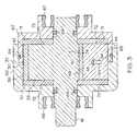
- FIG. 3is a section taken at line 3 — 3 of FIG. 2;
- FIG. 4is an exploded, perspective view of the damper of FIG. 2 .
- the rotary damper of the present inventionmay be used in a suspension system for a vehicle, generally designated 10 .
- the suspension system 10includes a pair of disk and hub assemblies 12 upon which wheels (not shown) are mounted.
- a knuckle 14extends generally outwardly from each disk and hub assembly 12 , and a shaft 16 is pivotally attached to the knuckle.
- shock forcesare applied to a wheel, the wheel and associated disk and hub assembly 12 are vertically displaced, as indicated by the arrow A.
- the displacementcauses the shaft 16 to pivot about end 18 as shown by arrow B.
- the shafts 16are coupled to rotary dampers 20 , 21 that damp the rotation of the shaft 16 and vertical movement of the disk and hub assemblies 12 .
- the damper 20includes a rotor 22 having a hub 24 and a pair of opposed, radially outwardly extending lobes 26 , 27 .
- Each lobe 26 , 27includes a pair of side faces 28 and an outer, arcuate surface 30 .
- the rotor 22 of the damper 20utilizes two opposed lobes 26 , 27 it is within the scope of the present invention to provide other numbers of lobes, including a single lobe or more than two lobes.
- the rotor 22is shaped to be received in a housing 32 .
- the housing 32includes an inner surface 34 defining a chamber 36 .
- the housing 32is preferably cylindrical forming a cylindrical internal chamber 36 .
- the housing 32is preferably made from a ferromagnetic material, such as mild steel.
- the lobes 26 , 27 of the rotor 22are shaped to form a small outer gap 38 with the housing 32 .
- the rotor 22divides the chamber 36 into a plurality of discreet volumes or cavities 40 a , 40 b , 40 c and 40 d inside the chamber 36 .
- the outer periphery of each lobe 26 , 27includes a magnet 42 preferably forming the outer surface of the lobes 26 , 27 .
- the damper 20includes a pair of opposing, wedge-shaped guide plates 44 , 45 that extend generally radially inwardly toward the hub 24 .
- the guide plates 44 , 45preferably are made from a non-magnetic material, such as aluminum.
- the hub 24 of the rotor 22is positioned between the guide plates 44 , 45 such that the hub 24 is adjacent to the inner surfaces 46 of each guide plate 44 , 45 .
- Each guide plate inner surface 46is arcuate in shape and is shaped to form a small inner gap 48 with the hub.
- Each of the guide plates 44 , 45includes an inner magnet 50 adjacent to the rotor hub 24 and forming the inner surface 46 . As shown in FIG.
- each guide plate 44 , 45includes a check valve 52 , 53 that is in fluid communication with the chamber 36 via conduits 54 , 55 .
- Conduit 54extends through guide plate 44 to connect adjacent volumes 40 d , 40 a and conduit 55 extends through guide plate 45 to connect adjacent volumes 40 b , 40 c .
- the operation of the check valves 52 , 53will be discussed in greater detail below.
- the chamber 36is preferably filled with magnetorheological fluid 56 , which is a fine iron powder or fine iron alloy particles suspended in a liquid base, such as mineral oil or silicone.
- magnetorheological fluid 56is a fine iron powder or fine iron alloy particles suspended in a liquid base, such as mineral oil or silicone.
- the suspension of ferromagnetic particles in a fluid mediumis known to affect the rheology of the medium in which the particles are suspended, particularly when subjected to a magnetic flux.
- the flow characteristics of the fluid 56such as viscosity, can change by several orders of magnitude when the fluid 56 is subjected to a magnetic field of sufficient strength.
- the magnetorheological fluid 56preferably has one or more additives that prevent the iron from separating out from the liquid base.
- the dampers 20 , 21are mounted to the frame or body (not shown) of an associated vehicle such that when the shaft 16 is rotated due to shock forces applied to the disk and hub assembly 12 , the rotary forces are transmitted to the hub 24 .
- the shock forcescause the hub 24 to rotate clockwise or counterclockwise in the chamber 36 , depending upon the direction of travel of the wheel and hub assembly 12 and the orientation of the damper 20 , 21 .
- an upward displacement of the disk and hub assembly 12preferably causes the rotor 22 to rotate clockwise.
- FIG. 2is a cross section of the damper 20 looking along line C of FIG. 1 .
- the motion of lobe 26 toward guide plate 44decreases the volume 40 d
- the motion of the lobe 27 toward the guide plate 45decrease the volume 40 b
- the fluid 56seeks to flow into the chambers having lower pressure ( 40 a , 40 c ).
- magnetorheological fluid 56flows through orifices 54 , 55 and into volumes 40 a , 40 c . Fluid flowing through the orifices 54 , 55 impinges upon the balls 76 , 77 and compresses the springs 78 , 79 thereby and opening the valves 52 , 53 .
- fluidalso flows through the inner gap 48 and the outer gap 38 in a controlled manner.
- flowmay fluid from the chamber 40 d to the chamber 40 c via the outer gap 38 located adjacent lobe 26
- fluid 56may flow from the chamber 40 d to the chamber 40 a via the inner gap 48 located adjacent guide plate 44 .
- fluidmay flow from the chamber 40 b to the chamber 40 a via the outer gap 38 located adjacent the lobe 27
- fluidmay flow from the chamber 40 b to the chamber 40 c via the inner gap 48 located adjacent the guide plate 45 .
- the restricted flow of fluid through orifices 54 , 55 and the inner gaps 48 and outer gaps 38resists the rotation of the rotor 22 , thereby damping the motion of the shaft 16 .
- the flow of magnetorheological fluid through the outer gap 38 and inner gap 48is preferably restricted to provide greater control over the damping.
- the outer magnets 42restrict the flow of magnetorheological fluid 56 between the outer surface 30 of the rotor 22 and the inner surface 34 of the housing 32 .
- the viscosity of the fluid 56increases in the presence of a magnetic field, and the increased viscosity restricts the flow of fluid through the outer gaps 38 . It is believed that the iron particles in the magnetorheological fluid 56 align in the presence of a magnetic field, which increases the viscosity of the fluid 56 .
- the increased viscosityadds a shear force that any fluid 56 must overcome in order to flow through the outer gap 38 . In this manner, a controllable, restrictive seal is effectively formed between the rotor 22 and the housing 32 at the outer gaps 38 .
- the outer magnets 42act to restrict the flow of the magnetorheological fluid 56 through the outer gaps 38 in a radial direction (i.e. a direction generally opposite the movement of the rotor 22 ) by restricting the flow of fluid 56 across the outer surface 30 of the rotor 22 .
- the inner magnets 50help to provide a controllable, restrictive seal between the hub 24 of the rotor 22 and the inner surface 46 of the guide plates 44 , 45 .
- the magnets 42 , 50may be positioned at various locations in the damper 20 , so long as they are close enough to the outer gap 38 to restrict the flow in the outer gap 38 in the desired manner.
- the outer magnets 42may be located on the housing 32 instead of the rotor 22 .
- the inner magnets 50may be located on the hub 24 instead of on the guide plates 44 , 45 .
- the housing 32is generally cylindrical such that the inner surface 34 of the housing 32 , the outer surface 30 of the rotor 22 , the outer surface of the hub 24 , and the inner surface 46 of the guide plates 44 , 45 are shaped generally cylindrically shaped; that is, they are shaped as a cylinder or as a segment of a cylinder, and thus are circular or arcuate in side view.
- magnets in the presence of magnetorheological fluid to form sealsmay be used in a variety of dampers without departing from the scope of the present invention.
- a permanent magnetmay be used to restrict the flow of magnetorheological fluid in non-rotary dampers such as linear motion dampers.
- the actuation of the check valves 52 , 53 when the rotor 22 is moved in the clockwise directionprovides additional fluid flow from a high pressure chamber to a lower pressure chamber, which provides additional damping. It is often desirable to provide additional damping when the vehicle wheel is moved upwardly. Shock forces in the upward direction are typically stronger, thereby necessitating a greater shock absorption.
- the check valves 52 , 53are typically oriented such that when the rotor 22 moves in a direction that corresponds to an upwardly-directed shock force, the fluid 56 can flow through the check valves 52 , 53 .
- the check valves 52 , 53remain closed.
- any type of relief or blow-off valve or other means for providing additional fluid flowsuch as deflected disk valving, may be used in place of the check valves 52 , 53 in the illustrated embodiments.
- only a single lobe 26may be used in the damper 20 .
- the chambers 40 a , 40 bmay not be present and the guide plates 44 , 45 may extend into the volume occupied by the chambers 40 a , 40 b , and lobe 27 in FIG. 2 .
- the valves 52 , 53may also be eliminated in this embodiment.
- the damper 20may include only a single lobe 26 , and the guides plates 44 , 45 and lobe 27 of FIG. 2 may be eliminated.
- the housing 32includes an inner housing 62 fit into a shoulder 63 in an outer housing 60 with an O-ring 64 therebetween.
- the housing 32includes a pair of bearings 66 , 67 to guide the rotation of the shaft 16 , and a pair of seals 68 , 69 are located between the shaft 16 and housing 32 to maintain the fluid in the housing 32 .
- the damper 20further includes a pair of plates 70 , 71 , made of ferromagnetic material such as mild steel, located on either end of the chamber 36 .
- the magnetic plates 70are located on opposed sides of the rotor 22 , and aid in sealing the chamber 36 by increasing the viscosity of the fluid in the presence of the plates.
- a pair of side gaps 72 , 73may be formed between the magnetic plates 70 , 71 , respectively, and the rotor 22 and/or guide plates 44 , 45 , and there may exist a relatively small amount of fluid 56 in the side gaps 72 , 73 .
- the fluid in the side gaps 72 , 73does not substantially contribute to the damping of the rotor 22 , and fluid 56 does not generally flow in the side gap 72 , 73 .
- a set of bolts 74extend through the outer housing 60 , plate 70 , guide plates 44 , 45 , plate 71 , and the inner housing 62 to couple the various components of the damper 20 together.
Landscapes
- Engineering & Computer Science (AREA)
- Mechanical Engineering (AREA)
- General Engineering & Computer Science (AREA)
- Physics & Mathematics (AREA)
- Electromagnetism (AREA)
- Fluid-Damping Devices (AREA)
Abstract
Description
Claims (2)
Priority Applications (1)
| Application Number | Priority Date | Filing Date | Title |
|---|---|---|---|
| US09/326,389US6318522B1 (en) | 1999-06-04 | 1999-06-04 | Rotary damper with magnetic seals |
Applications Claiming Priority (1)
| Application Number | Priority Date | Filing Date | Title |
|---|---|---|---|
| US09/326,389US6318522B1 (en) | 1999-06-04 | 1999-06-04 | Rotary damper with magnetic seals |
Publications (1)
| Publication Number | Publication Date |
|---|---|
| US6318522B1true US6318522B1 (en) | 2001-11-20 |
Family
ID=23271998
Family Applications (1)
| Application Number | Title | Priority Date | Filing Date |
|---|---|---|---|
| US09/326,389Expired - LifetimeUS6318522B1 (en) | 1999-06-04 | 1999-06-04 | Rotary damper with magnetic seals |
Country Status (1)
| Country | Link |
|---|---|
| US (1) | US6318522B1 (en) |
Cited By (43)
| Publication number | Priority date | Publication date | Assignee | Title |
|---|---|---|---|---|
| US6547043B2 (en)* | 2000-01-31 | 2003-04-15 | Delphi Technologies, Inc. | Tuneable steering damper using magneto-rheological fluid |
| US6550565B2 (en)* | 2000-02-18 | 2003-04-22 | Delphi Technologies, Inc. | Variable road feedback device for steer-by-wire systems |
| US20030085086A1 (en)* | 2001-11-07 | 2003-05-08 | Delphi Technologies Inc. | Magnetorheological steering damper |
| GB2382638A (en)* | 2001-11-30 | 2003-06-04 | Visteon Global Tech Inc | A magneto-rheological fluid-controlled vehicle suspension damper |
| US20030111308A1 (en)* | 2001-12-17 | 2003-06-19 | Vanvalkenburgh Charles Nicholas | Rotary damper |
| US20030126717A1 (en)* | 2001-12-12 | 2003-07-10 | Hiroyuki Iwashita | Rotary damper device |
| US20040084887A1 (en)* | 2002-10-30 | 2004-05-06 | Ford Global Technologies, Inc. | Semi-active control of automotive steering system vibration with magneto-rheological damping |
| US20040211632A1 (en)* | 2003-03-20 | 2004-10-28 | Honda Motor Co., Ltd. | Rotary Damper |
| US20050103585A1 (en)* | 2003-11-14 | 2005-05-19 | Crf Societa Consortile Per Azioni | Controlled oscillating damper |
| US20050145428A1 (en)* | 2003-02-21 | 2005-07-07 | Chun Wendell H. | Articulated vehicle suspension system shoulder joint |
| US20050258009A1 (en)* | 2004-05-19 | 2005-11-24 | Bauerfeind Ag | Controllable motion damper |
| US20050274582A1 (en)* | 2004-06-09 | 2005-12-15 | Takao Tomonaga | Rotary damper |
| US20070000732A1 (en)* | 2003-10-08 | 2007-01-04 | Richard Kulak | Elevator roller guide with variable stiffness damper |
| US20070085291A1 (en)* | 2005-10-17 | 2007-04-19 | Jong-Gil Lee | Vibration damping apparatus for steering systems |
| US20070125609A1 (en)* | 2005-12-07 | 2007-06-07 | O'leary Michael F | Transmission damping apparatus and method |
| US20070209902A1 (en)* | 2006-03-10 | 2007-09-13 | Muetzel Ronald P | Electrorheological inertia brake |
| US20080018070A1 (en)* | 2006-07-21 | 2008-01-24 | Gottschalk Michael J | Self-steering axle suspension system having a rotary stabilizer |
| US20080127453A1 (en)* | 2005-03-04 | 2008-06-05 | Wen-Lin Zhang | Auto-door device |
| US7416062B1 (en) | 2003-10-23 | 2008-08-26 | The United States Of America As Represented By The Administrator Of The National Aeronautics And Space Administration | Torsional magnetorheological device |
| US7726426B2 (en) | 2003-02-21 | 2010-06-01 | Lockheed Martin Corporation | Hub drive and method of using same |
| US20120227537A1 (en)* | 2011-03-07 | 2012-09-13 | Michael Lin | Flywheel assembly for exercise devices |
| EP2525114A1 (en)* | 2011-05-20 | 2012-11-21 | Research In Motion Limited | Low profile rotary damper |
| US8540062B2 (en) | 2011-05-20 | 2013-09-24 | Research In Motion Limited | Low profile rotary damper |
| US8550192B2 (en) | 2003-02-21 | 2013-10-08 | Lockheed Martin Corporation | Payload module for mobility assist |
| ITFI20120151A1 (en)* | 2012-07-18 | 2014-01-19 | Univ Firenze | STEERING SERIES FOR MOTORCYCLES INTEGRAL VEHICLES OF STEERING DAMPERS |
| US8672065B2 (en) | 2003-02-21 | 2014-03-18 | Lockheed Martin Corporation | Vehicle having an articulated suspension and method of using same |
| US20140271079A1 (en)* | 2013-03-15 | 2014-09-18 | Deere & Company | Hydraulic grapple damper |
| US8839891B2 (en) | 2003-02-21 | 2014-09-23 | Lockheed Martin Corporation | Multi-mode skid steering |
| CN105626756A (en)* | 2016-03-09 | 2016-06-01 | 中国人民解放军装甲兵工程学院 | Vane oscillating type magnetorheological shock damper |
| JP2016516162A (en)* | 2013-03-15 | 2016-06-02 | デレガレラ ホールディングス リミテッドDeregallera Holdings Ltd | Torsion device |
| US20160273642A1 (en)* | 2015-03-17 | 2016-09-22 | Hyundai Motor Company | Roll mount using magnetorheological fluid |
| CN107143599A (en)* | 2017-05-31 | 2017-09-08 | 合肥工业大学 | Big torque progressive rotation type MR damper |
| JP2017211019A (en)* | 2016-05-25 | 2017-11-30 | オイレス工業株式会社 | Rotary damper |
| US20180058110A1 (en)* | 2016-08-24 | 2018-03-01 | Francis Colligan | Door Latch With Delayed Return Mechanism |
| WO2018154119A1 (en) | 2017-02-24 | 2018-08-30 | Inventus Engineering Gmbh | Chassis component having a rotary damper |
| WO2018154112A1 (en) | 2017-02-24 | 2018-08-30 | Inventus Engineering Gmbh | Rotary damper |
| US10400846B2 (en)* | 2014-11-11 | 2019-09-03 | Oiles Corporation | Rotary damper |
| DE102018116187A1 (en) | 2018-07-04 | 2020-01-09 | Inventus Engineering Gmbh | rotary damper |
| US11161386B2 (en)* | 2017-09-05 | 2021-11-02 | Bayerische Motoren Werke Aktiengesellschaft | Switchable stabilizer assembly of a vehicle |
| US11439521B2 (en) | 2017-02-24 | 2022-09-13 | Inventus Engineering Gmbh | Prosthesis device with a rotary damper |
| US11585407B2 (en) | 2020-01-09 | 2023-02-21 | Beijingwest Industries Co., Ltd. | Rotary damper assembly |
| US20230064598A1 (en)* | 2020-02-27 | 2023-03-02 | Dyson Technology Limited | Robotic device |
| US20240227965A1 (en)* | 2023-01-06 | 2024-07-11 | Intellectual Property Holdings, Llc | Powered two-wheel vehicle |
Citations (9)
| Publication number | Priority date | Publication date | Assignee | Title |
|---|---|---|---|---|
| US3613842A (en)* | 1969-08-11 | 1971-10-19 | Peter Buciak | Hydraulic arcuately oscillating shock absorber |
| US4716996A (en)* | 1985-07-20 | 1988-01-05 | Hermann Hemschedit Maschinenfabrik Gmbh & Co. | Hydraulic rotation damper |
| US5081882A (en) | 1987-09-04 | 1992-01-21 | Seiko Seiki Kabushiki Kaisha | Damper device for a motor |
| US5305858A (en)* | 1991-07-22 | 1994-04-26 | Toyoda Koki Kabushiki Kaisha | Rotary shock absorber having vanes with radial flow clearance |
| US5816372A (en) | 1994-09-09 | 1998-10-06 | Lord Corporation | Magnetorheological fluid devices and process of controlling force in exercise equipment utilizing same |
| US5845752A (en)* | 1997-06-02 | 1998-12-08 | General Motors Corporation | Magnetorheological fluid clutch with minimized reluctance |
| US5848678A (en)* | 1997-06-04 | 1998-12-15 | General Motors Corporation | Passive magnetorheological clutch |
| US5947238A (en)* | 1997-03-05 | 1999-09-07 | Lord Corporation | Passive magnetorheological fluid device with excursion dependent characteristic |
| US5988336A (en)* | 1997-08-19 | 1999-11-23 | Bayer Aktiengesellschaft | Clutch with electrorheological or magnetorheological liquid pushed through an electrode or magnet gap by means of a surface acting as a piston |
- 1999
- 1999-06-04USUS09/326,389patent/US6318522B1/ennot_activeExpired - Lifetime
Patent Citations (9)
| Publication number | Priority date | Publication date | Assignee | Title |
|---|---|---|---|---|
| US3613842A (en)* | 1969-08-11 | 1971-10-19 | Peter Buciak | Hydraulic arcuately oscillating shock absorber |
| US4716996A (en)* | 1985-07-20 | 1988-01-05 | Hermann Hemschedit Maschinenfabrik Gmbh & Co. | Hydraulic rotation damper |
| US5081882A (en) | 1987-09-04 | 1992-01-21 | Seiko Seiki Kabushiki Kaisha | Damper device for a motor |
| US5305858A (en)* | 1991-07-22 | 1994-04-26 | Toyoda Koki Kabushiki Kaisha | Rotary shock absorber having vanes with radial flow clearance |
| US5816372A (en) | 1994-09-09 | 1998-10-06 | Lord Corporation | Magnetorheological fluid devices and process of controlling force in exercise equipment utilizing same |
| US5947238A (en)* | 1997-03-05 | 1999-09-07 | Lord Corporation | Passive magnetorheological fluid device with excursion dependent characteristic |
| US5845752A (en)* | 1997-06-02 | 1998-12-08 | General Motors Corporation | Magnetorheological fluid clutch with minimized reluctance |
| US5848678A (en)* | 1997-06-04 | 1998-12-15 | General Motors Corporation | Passive magnetorheological clutch |
| US5988336A (en)* | 1997-08-19 | 1999-11-23 | Bayer Aktiengesellschaft | Clutch with electrorheological or magnetorheological liquid pushed through an electrode or magnet gap by means of a surface acting as a piston |
Cited By (76)
| Publication number | Priority date | Publication date | Assignee | Title |
|---|---|---|---|---|
| US6547043B2 (en)* | 2000-01-31 | 2003-04-15 | Delphi Technologies, Inc. | Tuneable steering damper using magneto-rheological fluid |
| US6550565B2 (en)* | 2000-02-18 | 2003-04-22 | Delphi Technologies, Inc. | Variable road feedback device for steer-by-wire systems |
| US20030085086A1 (en)* | 2001-11-07 | 2003-05-08 | Delphi Technologies Inc. | Magnetorheological steering damper |
| US6637558B2 (en)* | 2001-11-07 | 2003-10-28 | Delphi Technologies, Inc. | Magnetorheological steering damper |
| GB2382638A (en)* | 2001-11-30 | 2003-06-04 | Visteon Global Tech Inc | A magneto-rheological fluid-controlled vehicle suspension damper |
| GB2382638B (en)* | 2001-11-30 | 2003-10-15 | Visteon Global Tech Inc | Magnetorheological fluid-controlled vehicle suspension damper |
| US6681905B2 (en) | 2001-11-30 | 2004-01-27 | Visteon Global Technologies, Inc. | Magnetorheological fluid-controlled vehicle suspension damper |
| US6840355B2 (en) | 2001-12-12 | 2005-01-11 | Sankyo Seiki Mfg. Co., Ltd. | Rotary damper device |
| US20030126717A1 (en)* | 2001-12-12 | 2003-07-10 | Hiroyuki Iwashita | Rotary damper device |
| US20030111308A1 (en)* | 2001-12-17 | 2003-06-19 | Vanvalkenburgh Charles Nicholas | Rotary damper |
| US6899208B2 (en)* | 2001-12-17 | 2005-05-31 | Charles N. VanValkenburgh | Rotary damper |
| US6752425B2 (en)* | 2002-10-30 | 2004-06-22 | Ford Global Technologies, Llc | Semi-active control of automotive steering system vibration with magneto-rheological damping |
| US20040084887A1 (en)* | 2002-10-30 | 2004-05-06 | Ford Global Technologies, Inc. | Semi-active control of automotive steering system vibration with magneto-rheological damping |
| US8672065B2 (en) | 2003-02-21 | 2014-03-18 | Lockheed Martin Corporation | Vehicle having an articulated suspension and method of using same |
| US7261176B2 (en) | 2003-02-21 | 2007-08-28 | Lockheed Martin Corporation | Articulated vehicle suspension system shoulder joint |
| US20050145428A1 (en)* | 2003-02-21 | 2005-07-07 | Chun Wendell H. | Articulated vehicle suspension system shoulder joint |
| US9567005B1 (en) | 2003-02-21 | 2017-02-14 | Lockheed Martin Corporation | Multi-mode skid steering |
| US8550192B2 (en) | 2003-02-21 | 2013-10-08 | Lockheed Martin Corporation | Payload module for mobility assist |
| US7726426B2 (en) | 2003-02-21 | 2010-06-01 | Lockheed Martin Corporation | Hub drive and method of using same |
| US8839891B2 (en) | 2003-02-21 | 2014-09-23 | Lockheed Martin Corporation | Multi-mode skid steering |
| US20040211632A1 (en)* | 2003-03-20 | 2004-10-28 | Honda Motor Co., Ltd. | Rotary Damper |
| US20070000732A1 (en)* | 2003-10-08 | 2007-01-04 | Richard Kulak | Elevator roller guide with variable stiffness damper |
| US7416062B1 (en) | 2003-10-23 | 2008-08-26 | The United States Of America As Represented By The Administrator Of The National Aeronautics And Space Administration | Torsional magnetorheological device |
| US20050103585A1 (en)* | 2003-11-14 | 2005-05-19 | Crf Societa Consortile Per Azioni | Controlled oscillating damper |
| US6955249B2 (en)* | 2003-11-14 | 2005-10-18 | C.R.F. Societa Consortile Per Azioni | Controlled oscillating damper |
| US7278522B2 (en)* | 2004-05-19 | 2007-10-09 | Bauerfeind Ag | Controllable motion damper |
| US20050258009A1 (en)* | 2004-05-19 | 2005-11-24 | Bauerfeind Ag | Controllable motion damper |
| US20050274582A1 (en)* | 2004-06-09 | 2005-12-15 | Takao Tomonaga | Rotary damper |
| US7204354B2 (en)* | 2004-06-09 | 2007-04-17 | Showa Corporation | Rotary damper |
| US20080127453A1 (en)* | 2005-03-04 | 2008-06-05 | Wen-Lin Zhang | Auto-door device |
| US7380804B2 (en)* | 2005-10-17 | 2008-06-03 | Kia Motors Corporation | Vibration damping apparatus for steering systems |
| US20070085291A1 (en)* | 2005-10-17 | 2007-04-19 | Jong-Gil Lee | Vibration damping apparatus for steering systems |
| US20070125609A1 (en)* | 2005-12-07 | 2007-06-07 | O'leary Michael F | Transmission damping apparatus and method |
| US20070209902A1 (en)* | 2006-03-10 | 2007-09-13 | Muetzel Ronald P | Electrorheological inertia brake |
| US7360773B2 (en)* | 2006-07-21 | 2008-04-22 | Hendrickson Usa, L.L.C. | Self-steering axle suspension system having a rotary stabilizer |
| US7748724B2 (en)* | 2006-07-21 | 2010-07-06 | Hendrickson Usa, L.L.C. | Self-steering axle suspension system having a rotary stabilizer |
| US20080018070A1 (en)* | 2006-07-21 | 2008-01-24 | Gottschalk Michael J | Self-steering axle suspension system having a rotary stabilizer |
| US8418582B2 (en)* | 2011-03-07 | 2013-04-16 | Michael Lin | Flywheel assembly for exercise devices |
| US20120227537A1 (en)* | 2011-03-07 | 2012-09-13 | Michael Lin | Flywheel assembly for exercise devices |
| US8540062B2 (en) | 2011-05-20 | 2013-09-24 | Research In Motion Limited | Low profile rotary damper |
| EP2525114A1 (en)* | 2011-05-20 | 2012-11-21 | Research In Motion Limited | Low profile rotary damper |
| ITFI20120151A1 (en)* | 2012-07-18 | 2014-01-19 | Univ Firenze | STEERING SERIES FOR MOTORCYCLES INTEGRAL VEHICLES OF STEERING DAMPERS |
| JP2015524764A (en)* | 2012-07-18 | 2015-08-27 | ユニバーシタ’デグリ ストゥディ ディ フィレンツェ | Steering head for motorcycle with integrated steering braking means |
| US9399495B2 (en) | 2012-07-18 | 2016-07-26 | Universita Degli Studi Di Firenze | Steering head for motorcycles integrating steering damping means |
| WO2014013435A1 (en) | 2012-07-18 | 2014-01-23 | Universita' Degli Studi Di Firenze | A steering head for motorcycles integrating steering damping means |
| JP2016516162A (en)* | 2013-03-15 | 2016-06-02 | デレガレラ ホールディングス リミテッドDeregallera Holdings Ltd | Torsion device |
| US20140271079A1 (en)* | 2013-03-15 | 2014-09-18 | Deere & Company | Hydraulic grapple damper |
| US10400846B2 (en)* | 2014-11-11 | 2019-09-03 | Oiles Corporation | Rotary damper |
| US20160273642A1 (en)* | 2015-03-17 | 2016-09-22 | Hyundai Motor Company | Roll mount using magnetorheological fluid |
| US9689487B2 (en)* | 2015-03-17 | 2017-06-27 | Hyundai Motor Company | Roll mount using magnetorheological fluid |
| CN105626756B (en)* | 2016-03-09 | 2017-12-22 | 中国人民解放军装甲兵工程学院 | Blade swing type magneto-rheological vibration damper |
| CN105626756A (en)* | 2016-03-09 | 2016-06-01 | 中国人民解放军装甲兵工程学院 | Vane oscillating type magnetorheological shock damper |
| US10844925B2 (en) | 2016-05-25 | 2020-11-24 | Oiles Corporation | Rotary damper |
| EP3467337A4 (en)* | 2016-05-25 | 2020-02-26 | Oiles Corporation | Rotary damper |
| JP2017211019A (en)* | 2016-05-25 | 2017-11-30 | オイレス工業株式会社 | Rotary damper |
| CN109154350A (en)* | 2016-05-25 | 2019-01-04 | 奥依列斯工业株式会社 | Rotary damper |
| US20180058110A1 (en)* | 2016-08-24 | 2018-03-01 | Francis Colligan | Door Latch With Delayed Return Mechanism |
| US10822841B2 (en)* | 2016-08-24 | 2020-11-03 | Accurate Lock & Hardware Co. Llc | Door latch with delayed return mechanism |
| WO2018154119A1 (en) | 2017-02-24 | 2018-08-30 | Inventus Engineering Gmbh | Chassis component having a rotary damper |
| US11287009B2 (en) | 2017-02-24 | 2022-03-29 | Inventus Engineering Gmbh | Rotary damper |
| CN110325758A (en)* | 2017-02-24 | 2019-10-11 | 因文图斯工程有限公司 | Walking mechanism component with rotary damper |
| WO2018154112A1 (en) | 2017-02-24 | 2018-08-30 | Inventus Engineering Gmbh | Rotary damper |
| US11439521B2 (en) | 2017-02-24 | 2022-09-13 | Inventus Engineering Gmbh | Prosthesis device with a rotary damper |
| DE102017103811A1 (en) | 2017-02-24 | 2018-08-30 | Inventus Engineering Gmbh | Suspension component with a rotary damper |
| JP2020508422A (en)* | 2017-02-24 | 2020-03-19 | インベンタス エンジニアリング ゲーエムベーハーInventus Engineering Gmbh | Rotary damper |
| DE102017103810A1 (en) | 2017-02-24 | 2018-08-30 | Inventus Engineering Gmbh | rotary damper |
| US11280379B2 (en) | 2017-02-24 | 2022-03-22 | Inventus Engineering Gmbh | Chassis component with a rotary damper |
| CN107143599A (en)* | 2017-05-31 | 2017-09-08 | 合肥工业大学 | Big torque progressive rotation type MR damper |
| US11161386B2 (en)* | 2017-09-05 | 2021-11-02 | Bayerische Motoren Werke Aktiengesellschaft | Switchable stabilizer assembly of a vehicle |
| DE102018116187A1 (en) | 2018-07-04 | 2020-01-09 | Inventus Engineering Gmbh | rotary damper |
| WO2020008002A1 (en) | 2018-07-04 | 2020-01-09 | Inventus Engineering Gmbh | Rotary damper |
| US11585407B2 (en) | 2020-01-09 | 2023-02-21 | Beijingwest Industries Co., Ltd. | Rotary damper assembly |
| US20230064598A1 (en)* | 2020-02-27 | 2023-03-02 | Dyson Technology Limited | Robotic device |
| US12011966B2 (en)* | 2020-02-27 | 2024-06-18 | Dyson Technology Limited | Robotic device |
| US20240227965A1 (en)* | 2023-01-06 | 2024-07-11 | Intellectual Property Holdings, Llc | Powered two-wheel vehicle |
| US12227254B2 (en)* | 2023-01-06 | 2025-02-18 | Intellectual Property Holdings, Llc | Powered two-wheel vehicle |
Similar Documents
| Publication | Publication Date | Title |
|---|---|---|
| US6318522B1 (en) | Rotary damper with magnetic seals | |
| US5632361A (en) | Vibration damper, in particular for motor vehicles | |
| US6352143B1 (en) | Vibration damping system using a hydraulic damper with a field responsive fluid control | |
| EP1034383B1 (en) | Adjustable valve and vibration dampers utilizing same | |
| US6471018B1 (en) | Magneto-rheological fluid device | |
| US7578512B2 (en) | Suspension device for motor vehicles | |
| CN109630596B (en) | A Rotary Damping Adjustable Silicon Oil-Magnetorheological Torsional Vibration Damper | |
| JP2005042920A (en) | Damper | |
| CN112283281A (en) | A damping regulating valve and method for a shock absorber | |
| GB2266573A (en) | Variable damping force shock absorber | |
| CN108331876B (en) | A shock absorber damping regulating valve | |
| US6120046A (en) | Hydraulic torsional damper for a steering system | |
| CN110107636B (en) | A two-way magnetorheological damping regulating valve | |
| US20010009214A1 (en) | Hydraulic damper for suspension systems | |
| US5165506A (en) | Dynamically variable multi-disc rotary shock absorber with viscous fluid | |
| CN102242789B (en) | Damping valve device with a multi-stage damping characteristic curve | |
| EP1664585B1 (en) | Shock absorber | |
| US5193655A (en) | Variable damping force shock absorber with feature of linear and wide range damping force variation depending upon piston stroke speed | |
| US6439356B1 (en) | Controlled oscillating damper | |
| JP2025504640A (en) | Shock absorber with multiple damping control laws | |
| KR101190100B1 (en) | Rotary damper using smart fluids | |
| JPH05506915A (en) | Pre-acting hydraulic shock absorbers for automobiles | |
| JPS62251220A (en) | buffer | |
| KR20140028200A (en) | Valve assembly of dual frequency sensitive type | |
| US6622829B2 (en) | Rotary Damper |
Legal Events
| Date | Code | Title | Description |
|---|---|---|---|
| STCF | Information on status: patent grant | Free format text:PATENTED CASE | |
| AS | Assignment | Owner name:DELPHI TECHNOLOGIES, INC., MICHIGAN Free format text:ASSIGNMENT OF ASSIGNORS INTEREST;ASSIGNORS:OLIVER, MICHAEL LESLIE;KRUCKEMEYER, WILLIAM CHARLES;REEL/FRAME:012495/0752;SIGNING DATES FROM 20010724 TO 20010730 | |
| AS | Assignment | Owner name:DELPHI TECHNOLOGIES, INC., MICHIGAN Free format text:ASSIGNMENT OF ASSIGNORS INTEREST;ASSIGNORS:JOHNSTON, GARY LEE;LONGHOUSE, RICHARD EDWARD;HEBER, BRIAN PAUL;REEL/FRAME:012607/0514;SIGNING DATES FROM 20001205 TO 20001216 | |
| FPAY | Fee payment | Year of fee payment:4 | |
| FPAY | Fee payment | Year of fee payment:8 | |
| FEPP | Fee payment procedure | Free format text:PAYOR NUMBER ASSIGNED (ORIGINAL EVENT CODE: ASPN); ENTITY STATUS OF PATENT OWNER: LARGE ENTITY | |
| AS | Assignment | Owner name:BWI COMPANY LIMITED S.A., LUXEMBOURG Free format text:ASSIGNMENT OF ASSIGNORS INTEREST;ASSIGNOR:DELPHI AUTOMOTIVE SYSTEMS, LLC;REEL/FRAME:024892/0813 Effective date:20091101 | |
| FPAY | Fee payment | Year of fee payment:12 |