US6317387B1 - Method and apparatus for inspecting a submerged structure - Google Patents
Method and apparatus for inspecting a submerged structureDownload PDFInfo
- Publication number
- US6317387B1 US6317387B1US09/165,426US16542698AUS6317387B1US 6317387 B1US6317387 B1US 6317387B1US 16542698 AUS16542698 AUS 16542698AUS 6317387 B1US6317387 B1US 6317387B1
- Authority
- US
- United States
- Prior art keywords
- hull
- remotely operated
- operated vehicle
- ship
- acoustical
- Prior art date
- Legal status (The legal status is an assumption and is not a legal conclusion. Google has not performed a legal analysis and makes no representation as to the accuracy of the status listed.)
- Expired - Lifetime
Links
Images


Classifications
- G—PHYSICS
- G01—MEASURING; TESTING
- G01N—INVESTIGATING OR ANALYSING MATERIALS BY DETERMINING THEIR CHEMICAL OR PHYSICAL PROPERTIES
- G01N29/00—Investigating or analysing materials by the use of ultrasonic, sonic or infrasonic waves; Visualisation of the interior of objects by transmitting ultrasonic or sonic waves through the object
- G01N29/22—Details, e.g. general constructional or apparatus details
- G01N29/28—Details, e.g. general constructional or apparatus details providing acoustic coupling, e.g. water
- B—PERFORMING OPERATIONS; TRANSPORTING
- B63—SHIPS OR OTHER WATERBORNE VESSELS; RELATED EQUIPMENT
- B63B—SHIPS OR OTHER WATERBORNE VESSELS; EQUIPMENT FOR SHIPPING
- B63B59/00—Hull protection specially adapted for vessels; Cleaning devices specially adapted for vessels
- B—PERFORMING OPERATIONS; TRANSPORTING
- B63—SHIPS OR OTHER WATERBORNE VESSELS; RELATED EQUIPMENT
- B63B—SHIPS OR OTHER WATERBORNE VESSELS; EQUIPMENT FOR SHIPPING
- B63B59/00—Hull protection specially adapted for vessels; Cleaning devices specially adapted for vessels
- B63B59/06—Cleaning devices for hulls
- B63B59/08—Cleaning devices for hulls of underwater surfaces while afloat
- B—PERFORMING OPERATIONS; TRANSPORTING
- B63—SHIPS OR OTHER WATERBORNE VESSELS; RELATED EQUIPMENT
- B63B—SHIPS OR OTHER WATERBORNE VESSELS; EQUIPMENT FOR SHIPPING
- B63B79/00—Monitoring properties or operating parameters of vessels in operation
- B63B79/30—Monitoring properties or operating parameters of vessels in operation for diagnosing, testing or predicting the integrity or performance of vessels
- G—PHYSICS
- G01—MEASURING; TESTING
- G01N—INVESTIGATING OR ANALYSING MATERIALS BY DETERMINING THEIR CHEMICAL OR PHYSICAL PROPERTIES
- G01N29/00—Investigating or analysing materials by the use of ultrasonic, sonic or infrasonic waves; Visualisation of the interior of objects by transmitting ultrasonic or sonic waves through the object
- G01N29/04—Analysing solids
- G01N29/11—Analysing solids by measuring attenuation of acoustic waves
- G—PHYSICS
- G01—MEASURING; TESTING
- G01N—INVESTIGATING OR ANALYSING MATERIALS BY DETERMINING THEIR CHEMICAL OR PHYSICAL PROPERTIES
- G01N29/00—Investigating or analysing materials by the use of ultrasonic, sonic or infrasonic waves; Visualisation of the interior of objects by transmitting ultrasonic or sonic waves through the object
- G01N29/22—Details, e.g. general constructional or apparatus details
- G01N29/225—Supports, positioning or alignment in moving situation
- G—PHYSICS
- G01—MEASURING; TESTING
- G01N—INVESTIGATING OR ANALYSING MATERIALS BY DETERMINING THEIR CHEMICAL OR PHYSICAL PROPERTIES
- G01N29/00—Investigating or analysing materials by the use of ultrasonic, sonic or infrasonic waves; Visualisation of the interior of objects by transmitting ultrasonic or sonic waves through the object
- G01N29/22—Details, e.g. general constructional or apparatus details
- G01N29/26—Arrangements for orientation or scanning by relative movement of the head and the sensor
- G01N29/265—Arrangements for orientation or scanning by relative movement of the head and the sensor by moving the sensor relative to a stationary material
- G—PHYSICS
- G01—MEASURING; TESTING
- G01S—RADIO DIRECTION-FINDING; RADIO NAVIGATION; DETERMINING DISTANCE OR VELOCITY BY USE OF RADIO WAVES; LOCATING OR PRESENCE-DETECTING BY USE OF THE REFLECTION OR RERADIATION OF RADIO WAVES; ANALOGOUS ARRANGEMENTS USING OTHER WAVES
- G01S15/00—Systems using the reflection or reradiation of acoustic waves, e.g. sonar systems
- G01S15/87—Combinations of sonar systems
- G01S15/874—Combination of several spaced transponders or reflectors of known location for determining the position of a receiver
- G—PHYSICS
- G01—MEASURING; TESTING
- G01N—INVESTIGATING OR ANALYSING MATERIALS BY DETERMINING THEIR CHEMICAL OR PHYSICAL PROPERTIES
- G01N2291/00—Indexing codes associated with group G01N29/00
- G01N2291/01—Indexing codes associated with the measuring variable
- G01N2291/011—Velocity or travel time
- G—PHYSICS
- G01—MEASURING; TESTING
- G01N—INVESTIGATING OR ANALYSING MATERIALS BY DETERMINING THEIR CHEMICAL OR PHYSICAL PROPERTIES
- G01N2291/00—Indexing codes associated with group G01N29/00
- G01N2291/02—Indexing codes associated with the analysed material
- G01N2291/028—Material parameters
- G01N2291/02854—Length, thickness
- G—PHYSICS
- G01—MEASURING; TESTING
- G01N—INVESTIGATING OR ANALYSING MATERIALS BY DETERMINING THEIR CHEMICAL OR PHYSICAL PROPERTIES
- G01N2291/00—Indexing codes associated with group G01N29/00
- G01N2291/10—Number of transducers
- G01N2291/105—Number of transducers two or more emitters, two or more receivers
Definitions
- the present inventionrelates to an underwater apparatus, system and method for inspecting and determining the condition of a submerged structure whether it be a ship, drilling rig or any other underwater structure. Whether it be a regular routine inspection, or an inspection occasioned by an accident at sea, which may raise concerns respecting the structural integrity of the structure.
- the apparatusis particularly suited to inspect the hull of a ship without submitting the same to a costly dry dock procedure.
- the present inventiondoes not require the ship to be docked, as it is highly portable and can be deployed in any appropriate body of water. Moreover, the exact position of the hull being inspected is also determined. Accordingly, the size and location of any irregularities and/or defects in the hull of the ship or the coatings that protect it are determined to a tolerance of a few centimeters.
- Cost-efficient operation of a sea-going vesseldemands rigorous monitoring of the integrity of the hull.
- vesselsmust also be able to withstand the sometimes every violent forces experienced by ships at sea during storm and other less than ideal conditions, whether they be waves, wind, or combinations of the same.
- the heavy salt content of ocean waterwill tend to eat away at the material of which metal vessel hulls are made.
- the resultwill initially be minor pitting, which tends to be localized on account of the configuration of the ship's hull, the materials of which the hull are made, joints between various components of the hull, and other factors.
- Such corrosionwill compromise the overall integrity of the ship under normal operating conditions and, of course, could have catastrophic effects in the event of inclement weather or a collision with debris, another vessel, or on account of being run aground.
- the first line of defenseis the protection of the hull of a ship with an appropriate coating.
- coatingsare selected for their properties of long life in sea water, resistance to radiation, ability to discourage the growth of marine life on the surface of the hull of the ship, adhesion and general toughness, among others.
- a crucial element of the survey of a shipis the inspection of the coating, which is often the first element in the ship to indicate the onset of a problem in the overwhelming majority of situations.
- such a systemis intended to carry out, from a location on land, the multiple checks to which the hull of a ship must be subjected. Most importantly, it is intended to do this while the ship is afloat, thus avoiding the costs associated with submitting the ship to a costly dry dock procedure.
- Patent Cooperation Treaty International Application No. P. C. T./N 094/00060discloses a diver delivered unit which may be operated directly by a diver or otherwise in a measurement area marked by a plurality of lights.
- the unitis delivered to the area of the hull of a ship afloat in a harbor by a diver.
- the unitis moved over the hull of the ship by a diver, although the possibility of moving the unit on the surface of the hull without a diver is vaguely alluded to. While this disclosure is somewhat general, it appears to suggest that magnets may be used to adhere the unit to the hull of a ship while the unit is being propelled along the surface of the ship by thrusters.
- the inventionas claimed, is intended to provide a remedy. It solves the problem of how to provide a reliable, economical and consistent way of inspecting the hull of a ship without resorting to the costly procedure of dry docking the ship.
- the system of the present inventioncomprises a remotely operated vehicle (ROV) which can be introduced into the waters of a port from a position on the land (or even at or close to the site of an accident possibly far at sea).
- the ROVis equipped with inspection cameras, position sensing equipment and non-destructive test equipment adapted to inspect and measure the characteristics of the submerged hull to be inspected.
- the non-destructive test equipmentprovides measurement of key vessel parameters, including plate thickness, plate pitting, plate delamination, plate fracture, coating thickness, and cathodic protection device potential.
- An integrated data setcomprised of all measurements correlated in time and hull position, is generated and recorded at a controlled spatial resolution on the hull.
- the ROVis adapted to propel itself toward and over the surface of the submerged hull of the ship, being guided by either a human operator who steers the ROV from the control console (which may be on land or on the ship being inspected) using an on board camera and acoustic navigation system, or guided automatically by a computer which is programmed to execute a stored inspection sequence over the submerged hull.
- the position of the ROV on the hull provided by the acoustic navigation systemmay be initially determined by the placement of three or more electro-acoustic position transducers at known points on the hull of the ship.
- ROV adhesion to the surface of the submerged hullis achieved by employing a Bernoulli effect for steady state, incompressible flow across an orifice.
- a pressure dropis created in the direction of water flow.
- the reduced pressure within the suction zone(s)develops a suction force proportional to the product of pressure drop and suction zone area.
- the suction forceis largely normal to the hull at the suction zone, and in a direction which results in the suction device adhering to the hull.
- the interface of the suction zone and the hullis formed using a compliant skirt which provides good conformance to rough, uneven or undulating hull surfaces, while generating minimal drag and compression forces during ROV motion.
- movement of the ROV along the surface of the hull of the shipis achieved through a combination of thruster power and wheeled propulsion.
- the resultis the positive control of position by virtue of the contacting drive wheels and drive augmentation provided by the thrusters whose thrust assists the wheeled propulsion, both in direction and magnitude.
- the thrusters and the driven wheelscan share a common power plant, with the drive wheels driven directly by the propulsion thruster motors via mechanical connection.
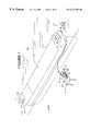
- FIG. 1is a perspective view of a ship docked at a facility equipped with the apparatus of present invention
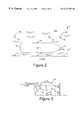
- FIG. 2is a plan view of a ship being inspected in accordance with the invention.
- FIG. 3is a cross-sectional view of a ship being inspected with the present invention along lines 3 — 3 of FIG. 2;
- FIG. 4is a schematic diagram of a position detecting system employed in the present invention.
- FIG. 5is a schematic diagram illustrating the electronic inspection system carried by a ROV inspection device constructed in accordance with the present invention
- FIG. 6is an elevational view of the ROV of present invention.
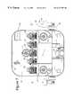
- FIG. 7is a plan view of the inventive ROV along lines 7 — 7 of FIG. 6;
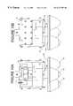
- FIG. 8is a side elevational view of the inventive ROV along lines 8 — 8 of FIG. 7;
- FIG. 9is a detailed view of the right thruster of the inventive ROV along lines 9 — 9 of FIG. 8;
- FIG. 10is a detailed view of the thruster of FIG. 9 inventive ROV along lines 10 — 10 of FIG. 9;
- FIG. 11is a detailed view of the thruster of FIG. 9 inventive ROV along lines 11 — 11 of FIG. 10;
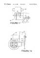
- FIG. 12is a detailed view of the thruster of FIG. 9 inventive ROV along lines 12 — 12 of FIG. 9;
- FIG. 13is a elevational view of the NDT sled of present invention.
- FIG. 14is a plan view of the inventive NDT sled along lines 14 — 14 of FIG. 13;
- FIG. 15Ais a side elevational view of the inventive NDT sled along lines 15 A— 15 A of FIG. 14;
- FIG. 15Bis a side elevational view of the inventive NDT sled along lines 15 B— 15 B of FIG. 14;
- FIG. 16is a flow chart illustrating the inventive process for inspection of a submerged structure
- FIG. 17is a flow chart illustrating the inventive process for post processing and data reporting of data gathered by the inventive process of FIG. 16;
- FIG. 18is a flow chart illustrating an alternative embodiment of the inventive software that controls the inventive apparatus.
- FIG. 19is a detailed drawing of a portion of the software of FIG. 18 .
- inventive method and apparatuswill be described with respect to a ship hull inspection, with the understanding that the present inventive method and apparatus may also be used to inspect oil rigs and other submerged structures.
- a ship 10 having a hull 11 or any other submerged structure requiring periodic inspection such as a dammay be equipped with an inspection system 12 constructed in accordance with the present invention.
- Inspection system 12comprises a topside computer controlled operator interface console 14 , a plurality of underwater transceivers 16 and a remotely operated vehicle (ROV) or robot, which functions as ROV 18 .
- the underwater transceivers 16are preferably mounted directly to the hull using one or more methods, however, the transceivers may also be mounted to fixed land based features (sea bed, pier pilings, etc.). In the latter case, it is also necessary to know the position of the ship with respect to the fixed transceiver network comprising transceivers 16 .
- transceivers 19it is necessary that a number of transceivers 19 sufficient to completely define the position of the ship be used. Such transceivers 19 should be secured to the hull 11 of the ship, and, in accordance with the present invention, are secured at minimum three points. See FIGS. 2 and 3.
- Console 14includes a computer network 20 (sometimes referred to herein as the “computer”), a keyboard 22 , an appropriate monitor 24 and an analog input device such as a joystick 26 .
- the systemalso includes a number of mass data storage units (magnetic disk drives, magneto-optical drives, etc) 28 which may be used for program and data storage and exchange.
- Power to the systemis provided by the power mains, which may be derived from shipboard power, pier-side power, or stand-alone generator sources.
- the power mainsprovide power for the integrated system, including topside controls, the underwater ROV, and acoustic transceivers.
- the underwater ROV 18is powered through an electrical cable (tether) 30 .
- transceivers 16 and 19are also powered by appropriate electrical cables 32 connecting the transceivers to the topside control consoles 14 .
- tether 30 and cables 32also carry information, control and associated signals, as will be set forth in detail below.
- Underwater ROVswhich are capable of movement underwater are known.
- the systems for controlling thrusters on board such ROVs to achieve desired movement of the ROVsare also known in the art.
- Such ROVs incorporating such control systemsare sold, for example, by the assignee of the present application.
- Such underwater vehiclesmay be modified in accordance with the teachings of the present specification and be employed in the system of the present invention to carry navigation equipment and appropriate inspection devices.
- transceivers 16are positioned underwater at a plurality of points which are selected to provide acoustic line-of sight communication for the emission of an acoustic signal from every point on the submerged hull 11 of the ship to transceivers 16 .
- a sufficient number of transceivers 16are placed so that this can be achieved with respect to at least three, and preferably more of the transceivers 16 from any point on the submerged hull.
- the hull of a ship 10is surveyed by ROV 18 in accordance with the present invention.
- One or more acoustic pingers 38 on ROV 18receives a signal from the console 14 , which causes it to emit an acoustic signal, which is received by transceiver 16 .
- the distance between the transceiver 16 and the pingers on ROV 18can then be calculated by computer network 20 based upon a calibrated speed of sound in the water and the acoustic travel time, i.e., the time between the emitted acoustic pulse at the pinger and the received pulse at the transceiver.
- a high accuracy sonic (acoustic) navigation and positioning system of the type sold under the trade name SNAP by the assignee of this application and specifically designed for precise underwater tracking of underwater ROVs and providing data at high update rates in high multipath environmentsis employed in the system of the present invention.
- ROV pinger to transceiver range (distance) errorsare less than 2 cm, repeatability is better than 0.5 cm., and sampling rates up to 10 Hz can be achieved with such prior art systems.
- Such high accuracy navigation systemsare adaptable for use in rivers, lakes, ponds, or the open ocean, but are exceptionally well-suited to high multipath environments such as harbors, enclosed tanks, dams or tunnels, under ice cover, beneath ships, and around submerged structures.
- Such high accuracy navigation systemsare based on a set of compact and durable acoustic transceivers 16 in the water around ship 10 , transceivers 19 on ship 10 , and pingers 38 on ROV 18 , each independently capable of transmitting and receiving high-frequency acoustic pulses.
- a computer network 20controls the acoustic network of transceivers and is used for data acquisition, and for the processing, display, and output of position data.
- Each transceiveris connected to the system controller through a twinaxial cable 32 which provides power and a data transfer path, as shown FIG. 1 .
- at least three transceivers 16are deployed to form a stationary baseline array and one or more, but preferably three, hull mounted transceivers 19 are tracked by the stationary baseline array.
- Each transceiver in this high accuracy navigation systemis independently controlled to transmit or receive acoustic pulses with an approximately hyper-hemispherical beam pattern.
- the transceiversare mounted in rugged, cylindrical, stainless steel, sealed pressure cases which allow easy deployment in a wide variety of applications.
- the high accuracy of the navigation systemis due to the use of broadband high frequency acoustic pulses centered at 300 kHz. As noted above, operating at the maximum range of 100 meters the range data is accurate to within at least +/ ⁇ 2 cm, and repeatable to within 0.5 cm. In order to obtain the accuracy stated above, speed of sound errors must be limited to 1 cm at 100 meters or 1 part per 10,000. Repeatability is not affected by sound speed errors, but will be affected by variations in the speed of sound over a period of hours or days.
- This high accuracy navigation systemis ordinarily operated in a “long baseline” mode.
- Other types of typical long baseline systemsoperate at much lower frequencies and consist of an array of transponders covering an area of 1,000 to 10,000 square meters.
- the ‘baseline’ transpondersare usually securely positioned on the sea floor using tripods, or allowed to float above the sea floor on moorings. System accuracy is dependent upon knowledge of these baselines, and unobstructed line-of-sight is required between the baseline transponders and the target to be positioned.
- the use of high frequency signalslimits the range (100 meters, typical at 300 kHz) and each of the baseline array elements is hard-wired to the computer.
- a wired baseline arrayforms a network of transceivers which can be referred to as a “net”, and the individual transceivers can be considered as “net elements”.
- the high accuracy navigation systemfirst commands the target pinger 38 to transmit a pulse.
- This pulseis received by the three (or more) network transceivers 16 , and the one-way travel times are determined. Using the estimated sound speed, these travel times are converted to slant ranges (distances). The slant ranges are then converted to the Cartesian (x,y,z) positions by knowledge of the geometry of the net elements.
- the computed position and orientation of the arraycan be adjusted during calibration so that these x,y,z positions are reported in a global coordinate system or one which is referenced with respect to some important features of the ship's hull 11 .
- the pingers 38are the sonic devices which the high accuracy navigation system uses to determine relative range and position of ROV 18 .
- Transceivers 19are used to determine ship position.
- Transceivers 16form the stationary array to which all ranges, from both ROV pingers 38 and hull-mounted transceivers 19 , are measured. All the transceivers are interchangeable, as each can transmit and receive acoustic signals. Thus, any of the transceivers may be used in the baseline array of transceivers 16 fixed with respect to the sea floor.
- the transceiversare connected to the twinaxial subsea cable 32 consisting of a 100 meter subsea twinaxial cable and a five meter deck cable. Longer subsea cable and deck cable lengths may also be employed.
- the deck unitprovides the connection between the cable 32 and host computer network 20 .
- a depth sensormay also be used to measure the depths of the transceivers in the baseline array so that the coordinate system can be adjusted to be level. It can also be used during tracking as a substitute for the high accuracy navigation system acoustic indicated depth or as an input to a filter which combines the two depth measurements to obtain an improved depth estimate.
- a tripod 40(FIG. 3) may be used to mount the baseline transceiver in applications requiring seabed installation. Telescoping legs allow stable installation in a rocky seabed, and a rotating and tilting mount supports aiming of the transceiver tip so as to optimize signal reception. Custom tripods or mounting fixtures can be designed for other applications.
- the inventive system 12comprises a computer network 20 .
- Computer network 20includes one or more computers for ROV navigation and ROV control (including position control).
- the ROV navigation and control functionsare provided by two computers, the navigation computer 42 and a ROV position control computer 44 .
- these two functions, navigation and controlwould be operating as two separate processes, or threads, within that computer.
- Navigation computer 42interfaces with appropriate navigation electronics contained on a board 46 adapted to send ROV pinger target position information to computer 42 and receive control signals from computer 42 .
- Navigation electronics 46are also coupled to the in-water navigation electronic systems associated with ROV 18 . Coupling of in-water systems associated with ROV 18 to navigation electronics 46 is achieved using tether 30 , as is illustrated in FIG. 4, which illustrates the principal elements of the electronic system, and the paths and directions used by information and drive signals during operation of the system.
- Console 20also includes digital data interface boards 52 which are coupled to an ROV position control computer 44 .
- boards 52are coupled to vehicle control signal lines which connect to the ROV 18 over tether 30 , via the vehicle power supply 54 .
- Informationmay be input into computer 44 through boards 52 by a joystick 26 whose output is switched by a switch 58 to either boards 52 or is connected directly to vehicle controls via the power supply 54 .
- This switch 58provides a method for the operator to control the vehicle manually without computer intervention, or the control computer 44 is capable of operating the vehicle in automatic mode, wherein the ROV is driven under software control through a course which is dynamically programmed. This course is determined by a series of waypoints determined by the operator, and the software controls the ROV to drive a track line, or trajectory, from one waypoint to the next.
- Vehicle power supply 54outputs an electrical power signal which is coupled by tether 30 to the ROV 18 .
- This electrical power signalprovides the power to operate the ROV 18 , including power for its vehicle movement systems, its inspection systems, and its position sensing systems.
- a monitor 24 and a keyboard 22Interface between the operator and the console is provided by a monitor 24 and a keyboard 22 .
- a single monitor and keyboardcan service the navigation computer 42 and a ROV position control computer 44 .
- the in-water systemsinclude ROV 18 and the on-board propulsion, navigation and inspection systems. More particularly, the ROV 18 carries appropriate inspection and navigation instrumentation, including inspection devices 70 , an orientation sensor 72 and a depth sensor 74 . The output of inspection devices 70 is communicated by tether 30 to an inspection computer 76 which is coupled to dedicated monitor 25 and keyboard 23 . Output from ROV navigation devices and all other on-board devices is communicated via the tether interface 60 and tether 30 to ROV position control computer 44 .
- the ROV 18also incorporates two or more pingers 38 , each of which includes a transducer 68 .
- a navigation camera 80is also coupled to tether interface 60 .
- the navigation camera 80 functionis augmented by an electrically controllable tilt unit 73 , illumination lamps 75 and with laser projectors 71 .
- the tilt unitcan point the camera and lasers through an angular arc of 180 degrees.
- the lasersare mounted to either side of the navigation camera, precisely aligned to the axis of the camera, to provide a visual measurement reference within the field of view of the camera image.
- the in-water systems for ROV 18are completed by a drive plant 78 , which provides the motive power for movement of ROV 18 .
- the function of the navigation system illustrated in FIG. 4is to determine the position of the ROV 18 by determination of the positions of ROV mounted pingers 38 . Because the shape of the hull 11 in most small areas is relatively flat, and the configuration of the ROV 18 is known together with the position of pingers 38 on ROV 18 , this determination of the position of pingers 38 at a large number of locations of ROV 18 on the hull 11 of ship 10 will provide the location of a large number of points on the hull 11 and thus the three dimensional shape of the hull 11 .
- measurements of hull 11 plate thickness, coating thickness, cathodic protection device potential and other measurements taken on the surface of the hull 11 of the shipmay be associated with these points in alphanumeric printouts (reports), topographical maps, and other 2-D and 3-D visualization methods illustrating and documenting the condition of the ship.
- Such imagesmay be enlarged and rotated in space, as required to provide the desired degree of specificity for examination of a particular condition on a particular ship.
- Transceivers 16each are comprised of a transducer 68 which can both transmit and receive. Transducers 68 on transceivers 16 or transceivers 19 , when driven by an appropriate electrical signal, will emit an acoustic signal. Transducers 68 , also on transceivers 16 and transceivers 19 , when excited by an acoustic signal will output an electrical signal to board 46 . The signals received and transmitted by transceivers 16 and 19 are connected via cables 32 to navigation electronics 46 .
- the determination of position informationbegins with pulses output by acoustic transducer 68 on ROV mounted pingers 38 .
- the signals which drive pingers 38are sent over tether cable 30 from the navigation electronics 46 which generates those signals.
- transceivers 16 and 19 , and pingers 38all operate at the same acoustic frequency.
- Such operationbeginning with the determination of the ship's position relative to the fixed transceiver net, includes the stimulation of one of the fixed transceivers 19 to cause its transducer 68 to emit an acoustic pulse at the desired acoustic frequency. This pulse is received by all of the net transceivers 16 .
- Each transceiver 16will then signal the decoding circuitry in the navigation electronics 46 that it has received an acoustic pulse. The time between the emission of the pulse from the particular transceiver 19 and its reception of that pulse at each of the transceivers 16 gives the distance between all transceivers 16 and the particular transceiver 19 .
- the position of the particular transceiver 19 in spacemay then be determined.
- it is not necessary ranges to more than three transceivers 16but using four or more ranges does afford the opportunity to obtain redundant information and check for errors or improve accuracy and repeatability.
- the above processcan be repeated for a second of the transceivers 19 .
- the processis also repeated again for a third of the transceivers 19 . Knowing the position of the three transceivers 19 attached to the hull 11 , provides a unique determination of the position and orientation of the hull with respect to the fixed transceiver net 16 .
- transceivers 16are used to determine the position of each of the pingers 38 on ROV 18 , and thus determine the position of the ROV and the corresponding points 77 (FIG. 8) on hull 11 being inspected and measured. This is done by each of the pingers 38 sending an acoustic pulse to all of the transceivers 16 , and then repeating the process for each of the remaining pingers 38 on ROV 18 , using triangulation to determine the position of each of the pingers 38 . Computer 46 then computes the position of the measurement instrumentation on ROV 18 using the same triangulation techniques it uses to determine the position of transceivers 19 and hull 11 . Since the position of the hull 11 is known, and its shape is known, the position of the instrumentation inspection points 77 on the hull 11 of the ship may be determined.
- the positions of each of the transceivers 19is known.
- the position and orientation of the shipis also known, and data collected over the cable during or about the time of the position determination operation can be associated with a particular point 77 on the hull 11 .
- the above operationsare performed through the use of the navigation electronics board 46 which sends information to the navigation computer 42 , which in turn calculates the position of the various targets.
- the corresponding position information, in x,y,z Cartesian formis sent to the ROV position control computer 44 .
- computer 44sends drive control information to the drive plant on the ROV 18 via the tether 30 .
- the computer softwarecalculates the appropriate drive control values by comparing the current position and orientation of the ROV to the desired position and orientation and computing drive values which cause the measured difference, or position state error, to be minimized.
- manual modethe operator performs this function by monitoring the ROV position and driving it by use of the joystick 26 .
- On board inspection devicesinclude one or more each of ultrasonic test (UT) measurement systems, eddy current test (ET) measurement systems, potential field measurement systems, and video inspection systems. Other measurement technologies may also be employed in similar fashion.
- UTultrasonic test
- ETeddy current test
- potential field measurement systemspotential field measurement systems
- video inspection systemsOther measurement technologies may also be employed in similar fashion.
- the ultrasonic measurement systememploys one or more non-contact, water path coupled transducers 82 .
- the devicescan be configured to operate at different water path distances, ultrasonic frequencies, focus characteristics, and orientations relative to the local hull surface to optimize the transducer performance for a specific desired measurement.
- the electrical characteristics of the signals which drive the transducers 82may be varied over time to achieve a wide range of functions g from a single transducer.
- Some of the transducers 82may generally comprise an ultrasonic emitter and an ultrasonic receiver for, respectively, emitting a test signal and receiving the reflected measurement signal.
- the eddy current measurement systemmay include one or more eddy current transducers 90 .
- Potential measurement systemincludes one or more transducers 93 for cathodic protection device potential measurement, as well as other measurement devices 94 .
- the systemalso carries an inspection camera 96 which enables visual inspection of the hull 11 of the ship 10 .
- Camera 96also includes appropriate controls for varying the nature of the visual inspection. More particularly, camera 96 is of the type which has electrically controllable camera pan 97 , electrically variable zoom functions and electrically controllable focusing. Operation of camera 96 can also be enhanced by provision of inspection lighting 98 .
- ROV 18comprises an outer body 100 which functions as a protective housing for the ROV internal components, and as the pressure boundary between the internal suction plenum 120 and external ambient pressure 121 .
- the frame member 116includes mounting provisions for the internal components and the outer body 100 .
- the outer body 100is removable to facilitate instrument calibration and vehicle maintenance. When assembled on frame 116 , outer body 100 forms a tight seal at the mounting interface to minimize fluid leakage into the suction zone.
- Internal componentsinclude one or more vehicle and non-destructive test equipment control modules 118 and 119 , internal inspection camera 96 with pan unit 97 and integrated lighting 98 , and non-destructive test instruments with associated fixtures 123 . It is also possible for the ROV 18 to carry other sensors and transducers, both internal and external to the outer body 100 . Vehicle navigation lights 75 may be mounted internal to the ROV 18 in the positions illustrated in FIG. 8 . The navigation lights will illuminate the area in front of the vehicle by projecting light through cutouts in the outer body 100 . As noted above, ROV 18 carries a navigation camera 80 , with integral tilt unit 73 , and two laser sources 71 for calibration of dimensional gauging system.
- the two laser sourcesproject parallel rays of laser light, with fixed, known spacing, onto the surface to be inspected.
- Surface featurescan be dimensionally gauged by imaging the feature of interest with the navigation camera 80 , then scaling the image from the visible laser “dots” projected on the image by the two laser sources.
- Suction plenumsinclude one or more suction thrusters 122 which flow water from the suction plenums 120 in the directions indicated by arrows 124 , and compliant skirt 127 mounted around the perimeter of the suction plenum 120 .
- the compliant skirt 127provides the interface between the suction plenum 120 and the hull, and functions to provide good conformance to rough, uneven or undulating hull surfaces, while generating minimal drag and compression forces.
- the result of the suction thrusters 122 in conjunction with the suction plenums 120 and compliant skirt 127 when the ROV is positioned or moving over the hull 11 of a ship,is to create a flow of water “under” ROV 18 in the directions indicated by arrows 126 , as is illustrated most clearly in FIG.
- suction plenum 120will operate at reduced pressure relative to the external ambient pressure 121 , causing ROV 18 to be forced by the pressure differential against the hull 11 of ship 10 .
- ROV 18also comprises a third wheel 114 , which is mounted for free rotation on a wheel support which rotates either freely in response to vehicle motion (passive wheel) or in controlled fashion in response to a control signal from the console to provide a steering function by movement of the wheel support subassembly in the directions of arrow 142 (actively controlled wheel). Wheel 114 is not driven, but merely serves to stabilize movement of the vehicle 18 on the surface of the hull 11 of the ship.
- the construction of the drive propulsion module 102is illustrated in detail in FIGS. 9 through 12.
- the construction of the drive propulsion moduleincludes include thrusters 104 and drive wheels 106 .
- Each of the thrusters 104comprises a drive unit 130 coupled to a turbine 108 .
- Each turbine 108includes a propeller 110 and a nozzle 112 .
- Power to the systemis provided by a drive unit 130 .
- Drive unit 130can be any prime mover, including electric motor, hydraulic motor, or other.
- Thruster propeller 110can be directly mounted to the rotational output shaft of drive unit 130 , or mounted as a rotational element on a fixed support shaft 111 and magnetically coupled to the prime mover 130 .
- Thruster nozzle 112is mechanically supported from multiple struts eminating from the drive unit housing.
- a drive pulley 132 and belt 133couples power from the thruster 104 to a reduction gearbox 134 .
- Belt 133passes through a hole or slot 135 in thruster nozzle 112 .
- Reduction gearbox 134couples power to a drive shaft 136 which drives gears 138 and 140 .
- Gear 140is directly coupled to wheel 106 .
- ROV 18is adapted and controllable to move in various directions corresponding to clockwise and counterclockwise movement of traction wheels 106 .
- steeringmay be provided by active rotation of follower wheel 102 in the directions indicated by arrow 142 .
- the NDT transducer fixtures (NDT “sled” assemblies) 123are illustrated in FIGS. 13 to 15 .
- the NDT sled assemblies 123maintain fixed transducer spacing (height above hull) and orientation relative to the local hull surface.
- the NDT sled assembliesare rigidly attached to the vehicle frame 116 via mounting plate 141 , and are spring loaded against the hull surface via four-bar linkages 142 and springs 143 .
- the NDT sled assembly base 144is attached to four-bar linkage 142 via pivot pins 145 and 146 . Pivot pins 145 permit limited (+/ ⁇ 30 degreees) pitch rotation (relative to horizontal) of the base assembly.
- pivot pins 146permit limited (+/ ⁇ 30 degreees) roll rotation (relative to horizontal) of the base assembly.
- the baseincludes 3 rolling or sliding contacts 140 which contact and move relative to the hull surface with low sliding or rolling friction.
- the 3 point hull contact provided by 140in conjunction with the base pitch and roll degrees of freedom and spring loaded four-bar linkage permits the base 144 to assume an orientation parallel to the local hull surface as it travels over the hull.
- Gimbal slide 147is mounted to the base unit 144 in perpendicular fashion, as illustrated in FIG. 13 .
- Gimbal slide 147 cross-sectionis T-shaped to accept mating transducer gimbal assembly 148
- the transducer gimbal assembly 148is free to slide vertically on the gimbal slide 147 and locked in position via set-screws at a desired height above the base unit 144 .
- the transducer gimbal assembly 148includes transducer clamp 149 for retaining cylindrical cross-sectioned transducers.
- the transducer clamp 149couples to the gimbal slide 148 via pitch gimbal 150 , and roll gimbal 151 .
- the roll gimbal 151contains a T-slot for mating to gimbal T shaped slide 147 .
- Each gimbal axisincludes knurled adjustment knobs connected to worm gearing for manual adjustment of the transducer orientation.
- the combined pitch and roll gimbals connecting the transducer clamp 149 to the gimbal slide 147permits orientation of the transducer relative to the hull surface at a desired angle of operation.
- the gimbal slide and gimbal assembly 148 with transducerpermits the distance between the clamped transducer face and the local hull surface to be adjusted by moving the gimbal assembly vertically on the slide, then locking it at the desired height.
- the NDT sled base 144incorporates a through hole directly under the gimbal assembly to permit a direct water path between the clamped transducer and local hull surface.
- Standard ultrasonic test transducers for metal thickness gaugingare readily adapted to underwater service.
- the cylindrical shape of the ultrasonic transducerspermits direct mounting in the NDT sled gimbal assembly clamp 149 .
- the water path for the ultrasonic transduceris adjusted via the gimbal slide using the procedure describe above.
- Standard eddy current transducers for coating thickness gauging and metal fracture detectionare typically not rated for continuous underwater service. Additionally, for accurate coating thickness measurement, the flat face of the cylindrical eddy current transducer must maintain contact with the hull surface.
- the eddy current probeis adapted for this invention by housing it in a cylindrical water-tight tube, with replaceable end cap which maintains contact with the hull surface during the inspection process.
- the replaceable end capis mad of suitable plastic material which provides low sliding friction, yet exhibits good resistance to abrasion.
- the water tight tube assembly with eddy current probeis spring loaded against the hull surface with enough force to maintain transducer contact with the hull.
- the NDT sled gimbal 148 assemblyis adapted for the spring loaded eddy current transducer.
- a fixed clamp with mating T-slotis attached to the top of the gimbal slide 147 .
- the gimbal assembly 148 with clamped eddy current probe in watertight containeris mounted on the gimbal slide 147 in normal fashion, but the gimbal assembly 148 is not clamped in place, leaving it free to move in a vertical fashion on the slide.
- a compression springis located between the fixed clamp and gimbal assembly 148 , applying constant force to the eddy current water tight tube assembly in the direction of the hull surface.
- the compression springis constrained by an internal metallic pin.
- the metallic pinis attached to the gimbal assembly 148 immediately adjacent to the gimbal slide 147 , and running vertically parallel to the gimbal slide 147 .
- the metallic pinis guided by and extends through a matched hole in the fixed clamp at the top of the gimbal slide 147 .
- the compression springis mechanically constrained throughout it's length by the internal pin and at it's ends by the gimbal assembly 148 and fixed clamp mounted to the top of the gimbal slide 147 .
- a ship 10When it is desired to employ the system of the present invention, a ship 10 is brought into a facility where it may be docked in a stable manner. The inspection process can be carried out with the ship docked along a pier, moored within a harbor, or moored at open sea. After the ship 10 is securely docked or moored, a number of transceivers 16 are deployed at positions fixed with respect to the shore and the sea floor. Any convenient method of secure connection may be employed to achieve this result. In particular, transceivers 16 may be secured directly at positions on the bottom or the sides of the harbor or near the shore. A tripod 40 may also be used to position a transceiver 16 where the same may be otherwise difficult.
- transceiversmay be attached to piles 152 as illustrated in FIG. 2 .
- the positions of transceivers 16are selected to provide for line-of-sight acoustic communication between the transceivers 16 and similar transceivers on ROV 18 .
- the position of the shipmay be determined by the placement of transceivers 19 on the ship, for example, at the positions illustrated in FIG. 2 along the centerline of the ship and about 2 meters below the surface.
- ROV 18is introduced into the water and caused to swim, unmanned, to the hull 11 of the ship through the use of its thrusters 104 , which propel it through the water to the hull 11 of the ship.
- Complete control of the flight path of the ROV 18 during the transit to the hullis achieved by varying the propulsion thrust in a forward/aft direction and vertical direction, and by varying the thrust generated moments for yaw, pitch and roll.
- Forward/aft directional controlis provided by the drive propulsion modules 102 acting in unison.
- Vehicle yaw controlis provided by asymmetrical operation of drive propulsion modules 102 .
- vehicle pitch and roll controlis provided by asymmetrical operation of suction thrusters 122 .
- ROV 18is caused to swim underwater.
- Navigationmay be automatically controlled by the computer network 20 during the initial part of the swim, or the same may be completely manually controlled.
- the samemay be performed under manual control of an operator at the console. The operator is presented with visual data during this part of the operation through the use of the navigation camera. In principle, the same may be assisted through the use of sonar or other appropriate instrumentation.
- the ROV 18may be caused to move automatically along a predetermined path. If, on the other hand, no such information exists, various instrumentation on the ROV may be used to cause it to move along a path defined by the intersection of the hull 11 of the ship 10 and the surface of the sea. After this shape has been defined, the ROV 18 can be caused to travel along paths at successfully lower levels until the entire surface of the ship is covered. Likewise, the inspection path can be controlled to follow lines of constant girth, with the vehicle traveling between port side water line and starbord side waterline, advancing bow to stern or stern to bow at the completion of each waterline to waterline pass.
- the inspection of the hull 11is carried on both electronically and visually during the course of such movement. It is contemplated in accordance with the present invention, because of the shape of many hulls 11 , operator intervention and/or guidance would be a part of the control of the movement of ROV 18 . Such operator intervention is guided by readings on instruments which show the depth, position and orientation of the ROV as well as the display of the environment surrounding the ROV 18 , which display is provided by the navigation camera 80 and inspection camera 121 .
- the overall inspection processis outlined in FIG. 16 .
- the processbegins by determining at step 156 whether there is an existing 3-D model of the shape of the hull 11 of the ship. If such a model exists, the software proceeds from step 156 to step 162 where it is determined if the inspection path is to be pre-programmed “off-line” (prior to the inspection). If it is desired to plan the inspection path off-line, then step 164 is performed to generate the inspection path plan. In step 164 , there are several options for generating the inspection path plan. If the ship has been previously inspected using the process described by this invention, the planned inspection path can be based on a previously stored inspection path.
- the inspection path planningcan be performed using a dedicated software program which accepts the 3-D hull shape model filename as input, and generates as output a file containing a series of straight line motion segments to be executed by the ROV control system during actual survey.
- Each straight line motion segmentconsists of a segment endpoint (desired final location and orientation of the ROV at the terminus of the straight line move), desired path velocity, and desired path acceleration.
- Generation of the straight line motion segments comprising the inspection pathcan be performed automatically or manually. If generated automatically, the path planning program will automatically create a series inspection paths according to one or more of the methods which were described above. One method generates a series of inspection paths parallel to the ship's waterline.
- a second methodgenerates a series of parallel paths around the girth of the ship, up to the ship's waterline. If generated manually, the inspection path will be created by an operator manually defining (via mouse or other input device) the straight line segments on the 3-D hull image displayed on the computer console.
- step 158the availability of ship hull plans from which a 3-D hull shape image can be created is determined (step 158 ).
- Appropriate plans for 3-D hull shape model generationinclude ship plate expansion drawings in conjunction with CAD generated 3-D hull form description drawings or ship table of offsets used for hull manufacture. Additionally, ship data such as forward, aft and mid-section drafts may be useful for inspection path planning performed at step 164 . If it is determined at step 158 that appropriate plans and data exist for 3-D hull model generation, then a dedicated software program can be used to generate the 3-D hull shape model in step 160 .
- the dedicated software programwill accept the filenames for the various ship plans and data as input, and generate the 3-D hull shape model file as output.
- Some forms of ship plans to be inputsuch as plate expansion drawings, may exist in paper drawing form only. In cases such as this, the plan may require digitization by manual methods (i.e., digitizing tablet) or automatic methods (i.e., scanner plus CAD program) prior to input for the 3-D hull shape model generation process.
- the ROV and associated tracking systemcan be used to generate the ship's 3-D hull shape in a form suitable for 3-D hull shape model generation.
- Hull profile datacan be generated by driving the ROV over the submerged hull surface while tracking and recording (on non-volitile media) the vehicle's position and orientation using the acoustic tracking system and ROV instrumentation.
- the recorded hull profile datacan then be used as input to a dedicated software program for generation of 3-D hull shape model from vehicle position and orientation tracking data.
- the ROV and associated tracking systemcan be used to identify and record the positions of the ship's plate vertices for incorporation of plate geometry information into the 3-D hull shape model.
- the on-hull surveystarts at step 166 .
- the first step in the process(step 166 ) is deployment of the acoustic tracking system per methods described previously. After deployment of the acoustic network, the network is registered to the ship's hull in step 168 .
- This processinvolves driving the ROV to 3 positions on the submerged portion of the hull within the range of the acoustic network, and recording the positions (in acoustic network based coordinates) of three hull features with known locations in the hull based reference frame.
- the control software program operating in the navigation computer 42is then directed to translate the acoustic network reference frame to the hull based reference frame.
- all ROV position and orientation data generated by the acoustic tracking systemwill be referenced to the hull based reference frame.
- the ROVAfter deployment and registration of the acoustic tracking system in steps 166 and 168 , the ROV is directed to proceed to the inspection steps.
- step 170if it is determined that automatic ROV path control is not desired, then the operator can manually pilot the vehicle to conduct the on-hull inspection in step 172 .
- the ROVis manually piloted over the surface of the hull, while the NDT instrumentation continuously tests and records the condition of the hull 11 .
- automatic ROV path controlis selected at step 170 , then the pre-planned path is displayed by the monitor in step 174 , and means are provided in the form of step 176 for a human operator to edit the path calculated by the computer.
- the operatorthen directs the computer to proceed to step 178 and controls the ROV to follow the prescribed inspection path. While this is being done the computer also directs the ROV NDT instrumentation to test and record the condition of the hull 11 . During this part of the operation, the computer is responsive to manual input control by a human operator who views the environs of the ROV through the navigation camera.
- the operatoris given the opportunity to review the hull condition data (step 180 ), and, if available, historical data for the same ship.
- the operatordetermines in step 182 whether more information needs to be taken in certain areas through the use of a detailed survey of that area, as discussed above. If specific areas are in need of more detailed inspection, the sequence repeats from step 170 . If there is no need to further inspect the hull within the current area of coverage provided by the acoustic tracking network, then it is determined at step 184 whether the complete submerged surface of the hull has been inspected.
- step 166the sequence starting at step 166 is repeated. If there are no additional areas of the submerged hull to be inspected, then the survey portion of the process is complete, and data post-processing can be started.
- the overall post-processing operationis outlined in FIG. 17 .
- the processbegins by determining at step 186 whether a it is desired to develop a 3-D model of the shape of hull from the acquired and recorded survey tracking data. If existing hull shape models do not exist, or the hull plans required to construct a 3-D hull shape model do not exist, then an empirical model can be developed in step 188 from the ROV tracking data taken during a survey. Additionally, if 3-D hull shape models do exist, it may still be desirable to generate an empirical model from actual survey tracking data for model refinement purposes.
- step 190the acquired data is analyzed and processed for data reporting and visualization. This step may involve identification and removal of “bad” data from the data set, data filtering (smoothing), data tagging (a hull plate identification can be associated with each data sample, based on sample location on the hull), and data statistical analysis.
- An industry standard alphanumeric text reportis generated in step 192 , consisting of tabulated NDT data measurements (hull thickness, coating thickness, cathodic protection device potential, etc.) and the positions on the hull where the measurements were taken. Additionally, the data can be sorted and reported on a hull plate by plate basis. Graphical representations of the survey data are generated in step 194 .
- Graphical representationsinclude two dimensional and three dimensional views of the hull or sections of the hull, with the data value at a location on the surface encoded using color, texture, or height above the surface.
- Hull material cross-sectionscan be generated along operator defined lines of intersection (e.g., making it possible to view hull thickness at a specified cross-section of the ship).
- all reports generated by the process described by this inventioncan be delivered in various “electronic” formats to the end user.
- the tabulated and graphical data reportscan be converted to HTML files, making it possible for the customer to review the survey reports using a standard internet web browser.
- the HTML report filescan be delivered on CD media for “local” browsing on a customer's PC, or the files can be embedded within a password protected web site for review over the internet.
- step 196it is determined if historical survey data exists for the specific ship. If previous survey data generated by the process covered by this invention exists, then step 198 can be used to provide documented hull condition trend analysis and predictive maintenance planning. It is also contemplated that changes in the overall shape of the inspected structure as compared to construction plans and/or a prior survey or surveys may indicate particular problems and appropriate measures taken.
- computers 42 , 44 and 76cooperate to execute the software algorithm of the present invention.
- FIG. 18generally similar components or parts performing analogous, corresponding or identical functions to those of the previous embodiment are numbered herein with numerals which differ from the previous embodiment by multiples of one thousand.
- the alternative processbegins by determining at step 1156 whether there is an existing model of the shape of the hull 11 of the ship. If such a model exists, the software proceeds from step 1156 to subroutine 1158 where a determination of the intersection of the surface of the sea and the hull 11 of the ship when the ship is afloat is made.
- Subroutine 1158the ROV 18 is caused to travel along the shape surface of the hull 11 corresponding to the intersection in order to verify the accuracy of the computer generated intersection shape and position.
- Subroutine 1160thus comprises a sequence of thruster commands and position sensing commands responsive to positional information feedback to cause the ROV to trace the shape of the intersection on the hull 11 of the ship at a point just below the surface of the water. Thereafter, the hull is surveyed by the ROV in the manner detailed below.
- step 1162the question is asked whether plans for the ship exist. If such question, which is shown on the screen of the computer, is answered in the affirmative, the user is directed to put the plans on a scanner and the program proceeds to subroutine 1164 , which is a package for scanning such plans and artificially generating a three dimensional picture in space as a matrix of numbers which describe the shape of the hull 11 of the ship. Once this has been done, subroutine 1164 directs the machine to proceed to subroutine 1158 . In this regard, the information respecting the weight of the ship is also introduced into subroutine 1158 in order to determine the waterline based on displacement of a volume of water equal to the weight of the ship.
- subroutine 1158After such determination has been made at subroutine 1158 , the shape of the intersection and its position is verified by subroutine 1160 , by an attempt by the ROV to trace the shape in the water.
- the computerproceeds to the inspection steps.
- a depth transducer adapted to provide very accurate depth information at depths close to the surfacemay be used as a feedback device when such transducer is mounted on ROV 18 .
- This informationcan be input into the computer to allow the computer to generate appropriate control signals to cause the ROV to trace the intersection, while the position determining ultrasonic system gathers intersection shape information.
- ROV 18The movement of ROV 18 is controlled by subroutine 1166 . After the intersection has been determined, ROV 18 is directed to proceed along a path parallel to the intersection and displaced downwardly from the intersection by a desired distance. This is achieved by subroutine 1168 , which provides this function in a manner substantially similar to similar functions in computer aided drafting applications and based upon an operator input or computer generated prediction of below the water hull shape.
- subroutine 1170controls ROV 18 to follow a path on the hull 11 as close as possible to the generated parallel path and to generate actual path shape based on its movement.
- the navigation camera on board ROV 18provides a display to the operator at the console, and the human operator may vary the path followed by the ROV through an interactive subroutine 1171 .
- subroutine 1172is comparing actual path of movement information to generated path information to determine the difference between predicted hull shape and the actual contours of the area of the hull that the ROV is passing over.
- a separate subroutine 1174provides the computer network 20 in the console with measurement information from the various transducers on the ROV in order to map inspection information on the condition of the hull 11 .
- step 1176the question is asked by the computer as to whether it appears that the entire surface of the ship that is underwater have been surveyed. If the answer is yes, a complete map of the shape of the hull 11 has been produced and this information can then be used to proceed to the detailed portion of the inspection, as will be described below. If more of the hull 11 needs to be surveyed, the computer is directed to return to subroutine 1168 and generate the next lower parallel path. This process is repeated until the entire hull 11 is surveyed.
- subroutine 1178determines and displays the path for the ROV 18 to follow in order to inspect the entire surface of the hull 11 of the ship.
- the pathis displayed by the monitor and means are provided in the form of a subroutine 1180 for a human operator to edit the path calculated by the computer operating in accordance with subroutine 1178 .
- the computerthen proceeds to step 1182 and controls the ROV to follow the path determined by subroutine 1178 as edited by subroutine 1180 .
- subroutine 1182is responsive to human user input control provided by subroutine 1184 .
- Such interactive human interventionis provided by a human operator who views the environs of the ROV through the navigation camera.
- the computerAfter data has been gathered with respect to position and the corresponding hull 11 condition, whether through the completion of subroutine 1182 or the answering in the negative of the question of step 1176 , the computer is directed to proceed to assemble a model of the data as a function of position through the execution of subroutine 1186 .
- step 1188the question is asked as to whether previous data exists. If the answer is in the affirmative, the data is secured and a comparison is made by the computer at step 1190 . If no such data exists, the computer proceeds directly to step 1192 where a subroutine determines whether or not closer inspection of some areas is necessary.
- step 1194directs the system to repeat subroutines and steps 1186 through 1192 .
- step 1192is performed and a determination is made that no further detailed inspection is necessary, the report subroutine 1196 is actuated, report printed and the inspection is complete.
Landscapes
- Chemical & Material Sciences (AREA)
- Engineering & Computer Science (AREA)
- Physics & Mathematics (AREA)
- General Physics & Mathematics (AREA)
- Immunology (AREA)
- Biochemistry (AREA)
- General Health & Medical Sciences (AREA)
- Analytical Chemistry (AREA)
- Life Sciences & Earth Sciences (AREA)
- Pathology (AREA)
- Health & Medical Sciences (AREA)
- Combustion & Propulsion (AREA)
- Mechanical Engineering (AREA)
- Ocean & Marine Engineering (AREA)
- Radar, Positioning & Navigation (AREA)
- Remote Sensing (AREA)
- Acoustics & Sound (AREA)
- Computer Networks & Wireless Communication (AREA)
- Testing Or Calibration Of Command Recording Devices (AREA)
Abstract
Description
Claims (28)
Priority Applications (1)
| Application Number | Priority Date | Filing Date | Title |
|---|---|---|---|
| US09/165,426US6317387B1 (en) | 1997-11-20 | 1998-10-02 | Method and apparatus for inspecting a submerged structure |
Applications Claiming Priority (2)
| Application Number | Priority Date | Filing Date | Title |
|---|---|---|---|
| US6621297P | 1997-11-20 | 1997-11-20 | |
| US09/165,426US6317387B1 (en) | 1997-11-20 | 1998-10-02 | Method and apparatus for inspecting a submerged structure |
Publications (1)
| Publication Number | Publication Date |
|---|---|
| US6317387B1true US6317387B1 (en) | 2001-11-13 |
Family
ID=26746479
Family Applications (1)
| Application Number | Title | Priority Date | Filing Date |
|---|---|---|---|
| US09/165,426Expired - LifetimeUS6317387B1 (en) | 1997-11-20 | 1998-10-02 | Method and apparatus for inspecting a submerged structure |
Country Status (1)
| Country | Link |
|---|---|
| US (1) | US6317387B1 (en) |
Cited By (79)
| Publication number | Priority date | Publication date | Assignee | Title |
|---|---|---|---|---|
| US6571635B1 (en)* | 1998-09-03 | 2003-06-03 | BALTZERSEN øYSTEIN | Method and arrangement for inspection of buoyant objects |
| US6687583B1 (en)* | 1999-12-15 | 2004-02-03 | Yacht Watchman International | Vessel monitoring system |
| US6712017B2 (en)* | 2000-05-24 | 2004-03-30 | Tapiren Survey System Ab | Method and arrangement relating to inspection |
| US20050016269A1 (en)* | 2003-07-22 | 2005-01-27 | Igor Touzov | Structural Integrity Monitor |
| US20050052453A1 (en)* | 2003-09-08 | 2005-03-10 | Government Of The United States Of America As Represented By The Secretary Of The Navy | Technique for modeling shipboard systems and equipment |
| FR2861457A1 (en)* | 2003-10-28 | 2005-04-29 | Marc Serge Brussieux | Device for non-destructive testing of structures, particularly ship hulls, using number of non-destructive testing detectors and mobile robot to carry them |
| US20050099892A1 (en)* | 2003-11-06 | 2005-05-12 | Greelish Stephen J. | Method and apparatus for performing an ultrasonic survey |
| US20060060123A1 (en)* | 2000-05-24 | 2006-03-23 | Tapiren Survey System Ab | Method and arrangement for inspection of an object |
| US20060114748A1 (en)* | 2004-06-04 | 2006-06-01 | Hull Underwater Imaging Systems, Inc. | Underwater exterior ship hull imaging system employing a remote microprocessor controlled acoustic transducer array |
| US20060136424A1 (en)* | 2004-03-25 | 2006-06-22 | Jayasimha Nuggehalli | Approach for collecting and reporting status data from network devices |
| US20060251114A1 (en)* | 2004-03-25 | 2006-11-09 | Jayasimha Nuggehalli | Approach for collecting and reporting status data from network devices |
| US7143363B1 (en)* | 2002-07-25 | 2006-11-28 | Brunswick Corporation | Method for displaying marine vessel information for an operator |
| WO2007010265A1 (en)* | 2005-07-22 | 2007-01-25 | University Of Newcastle Upon Tyne | Apparatus for determining the position of a moveable apparatus on a surface |
| US7198001B1 (en)* | 2005-11-08 | 2007-04-03 | The United States Of America As Represented By The Secretary Of The Navy | Underwater inspection measurement survey |
| US7301851B1 (en)* | 2005-07-05 | 2007-11-27 | United States Of America As Represented By The Secretary Of The Navy | Underway hull survey system |
| US20080141778A1 (en)* | 2006-12-07 | 2008-06-19 | Thomas Bosselmann | Method of non-destructively testing a work piece and non-destructive testing arrangement |
| US20080193222A1 (en)* | 2007-02-14 | 2008-08-14 | Kroecker Stephan V | Maritime Port and Anti-Terrorism Data Gateway With Ingress And Egress Control |
| US20080260467A1 (en)* | 2007-04-20 | 2008-10-23 | Kroecker Stephan V | Maritime Port and Anti-Terrorist Data Gateway With Ingress and Egress Control |
| US20080300742A1 (en)* | 2007-05-30 | 2008-12-04 | Oceaneering International, Inc. | Hybrid remotely/autonomously operated underwater vehicle |
| WO2008054462A3 (en)* | 2006-02-24 | 2008-12-11 | Donald Rodocker | Underwater crawler vehicle having search and identification capabilities and methods of use |
| US20090147270A1 (en)* | 2007-12-07 | 2009-06-11 | Dirk Lehmann | System and method for investigating and/or determining the condition or state of a ship's hull |
| WO2009112582A1 (en)* | 2008-03-14 | 2009-09-17 | Single Buoy Moorings Inc. | Telemetry based data collection method and system for carrying out such method |
| US20100126403A1 (en)* | 2008-11-21 | 2010-05-27 | Rooney Iii James H | Hull Robot |
| US20100131098A1 (en)* | 2008-11-21 | 2010-05-27 | Rooney Iii James H | Hull robot with rotatable turret |
| EP1744156A3 (en)* | 2005-07-11 | 2010-06-02 | The Boeing Company | Ultrasonic array probe apparatus, system, and method for travelling over holes and off edges of a structure |
| US20100219003A1 (en)* | 2008-11-21 | 2010-09-02 | Rooney Iii James H | Hull robot steering system |
| US20110067615A1 (en)* | 2009-09-18 | 2011-03-24 | Rooney Iii James H | Hull robot garage |
| US20110083599A1 (en)* | 2009-10-14 | 2011-04-14 | Kornstein Howard R | Hull robot drive system |
| US20110191061A1 (en)* | 2008-06-30 | 2011-08-04 | Dcns | System for inspecting a hull of a ship and associated method |
| WO2011146103A1 (en)* | 2010-05-17 | 2011-11-24 | Raytheon Company | Vessel hull robot navigation subsystem |
| US20120266803A1 (en)* | 2008-10-17 | 2012-10-25 | Zediker Mark S | High power laser photo-conversion assemblies, apparatuses and methods of use |
| CN102818773A (en)* | 2011-06-08 | 2012-12-12 | 波音公司 | Laser surveillance system |
| US20120318187A1 (en)* | 2011-04-22 | 2012-12-20 | Jeff Condit | Underwater robotic venting and inspection system |
| US20130194413A1 (en)* | 2012-01-31 | 2013-08-01 | Clifford Hatcher | System and method for automated optical inspection of industrial gas turbines and other power generation machinery |
| WO2012061097A3 (en)* | 2010-10-25 | 2013-10-31 | Lockheed Martin Corporation | Sonar data collection system |
| EP2682782A1 (en)* | 2012-07-05 | 2014-01-08 | Roke Manor Research Limited | Sensor location method and system |
| US20140076225A1 (en)* | 2012-09-14 | 2014-03-20 | Raytheon Company | Autonomous Hull Inspection |
| US20140098215A1 (en)* | 2011-05-10 | 2014-04-10 | Alain Dinis | Method and device for viewing computer data contents associated with propulsion |
| US20140184794A1 (en)* | 2012-12-31 | 2014-07-03 | General Electric Company | Inspection systems and methods |
| US20140230713A1 (en)* | 2011-09-26 | 2014-08-21 | Kawasaki Jukogyo Kabushiki Kaisha | Underwater mobile inspection apparatus and underwater inspection equipment |
| US8855268B1 (en) | 2011-11-01 | 2014-10-07 | The Boeing Company | System for inspecting objects underwater |
| WO2015106104A1 (en)* | 2014-01-09 | 2015-07-16 | Oceaneering International, Inc. | Wireless data communications between a remotely operated vehicle and a remote location |
| US9116071B2 (en) | 2012-01-31 | 2015-08-25 | Siemens Energy, Inc. | System and method for visual inspection and 3D white light scanning of off-line industrial gas turbines and other power generation machinery |
| US9154743B2 (en) | 2012-01-31 | 2015-10-06 | Siemens Energy, Inc. | System and method for optical inspection of off-line industrial gas turbines and other power generation machinery while in turning gear mode |
| EP2732931A4 (en)* | 2011-07-15 | 2015-12-09 | Samsung Heavy Ind | Device for measuring location of underwater vehicle and method thereof |
| WO2016073244A1 (en)* | 2014-11-03 | 2016-05-12 | Sonasearch, Inc. | Integrity testing of storage tank structure using robotic ultrasound |
| US9709463B2 (en) | 2012-01-31 | 2017-07-18 | Siemens Energy, Inc. | Method and system for surface profile inspection of off-line industrial gas turbines and other power generation machinery |
| US9778141B2 (en) | 2012-01-31 | 2017-10-03 | Siemens Energy, Inc. | Video inspection system with deformable, self-supporting deployment tether |
| US9869174B2 (en)* | 2015-04-28 | 2018-01-16 | Vetco Gray Inc. | System and method for monitoring tool orientation in a well |
| WO2018052809A1 (en)* | 2016-09-15 | 2018-03-22 | Saudi Arabian Oil Company | Magnetically coupled integrated ultrasonic testing and cathodic protection measurement probe |
| WO2018052488A1 (en)* | 2016-09-15 | 2018-03-22 | Saudi Arabian Oil Company | Integrated ultrasonic testing and cathodic protection measurement probe |
| US9948835B2 (en) | 2012-01-31 | 2018-04-17 | Siemens Energy, Inc. | Single-axis inspection scope with spherical camera and method for internal inspection of power generation machinery |
| US9977127B2 (en)* | 2016-07-06 | 2018-05-22 | Hohai University | Ship draught detection apparatus and its detection method |
| US10011145B2 (en) | 2013-11-27 | 2018-07-03 | Em&I (Martime) Limited | Apparatus and method for inspecting flooded cavities in a floating offshore installation |
| WO2019005939A1 (en)* | 2017-06-30 | 2019-01-03 | Square Robot, Inc. | Method and apparatus for self-contained positioning of a mobile robot inside a tank |
| US10274718B2 (en) | 2012-01-31 | 2019-04-30 | Siemens Energy, Inc. | Single-axis inspection scope with anti-rotation extension and method for internal inspection of power generation machinery |
| US10281712B2 (en) | 2012-01-31 | 2019-05-07 | Siemens Energy, Inc. | Single-axis inspection scope with bendable knuckle and method for internal inspection of power generation machinery |
| EP3594676A1 (en)* | 2018-07-09 | 2020-01-15 | Westerton Access Limited | Subsea weld inspection system and method |
| CN111474245A (en)* | 2020-04-26 | 2020-07-31 | 中国石油天然气集团有限公司 | Nondestructive testing method for blowout preventer |
| US10884423B2 (en)* | 2016-12-23 | 2021-01-05 | Gecko Robotics, Inc. | System, method, and apparatus for acoustic and magnetic induction thickness inspection of a material on a substrate |
| US10996674B2 (en)* | 2019-03-19 | 2021-05-04 | Quest Integrated, Llc | Indoor positioning and navigation systems and methods |
| US11093877B2 (en)* | 2015-09-25 | 2021-08-17 | Fujifilm Corporation | Inspection plan drafting support system, method, and program |
| US11131759B2 (en)* | 2017-05-09 | 2021-09-28 | Thornton Tomasetti, Inc. | System, device and method for in-water inspection of maritime vessel acoustic treatments |
| US11135721B2 (en) | 2016-12-23 | 2021-10-05 | Gecko Robotics, Inc. | Apparatus for providing an interactive inspection map |
| US11307063B2 (en) | 2016-12-23 | 2022-04-19 | Gtc Law Group Pc & Affiliates | Inspection robot for horizontal tube inspection having vertically positionable sensor carriage |
| US11378553B2 (en)* | 2016-06-13 | 2022-07-05 | Elop As | Device, system and method for emission and reception of ultrasonic signals to and from a test material |
| WO2022140830A1 (en)* | 2020-12-30 | 2022-07-07 | Petróleo Brasileiro S.A. - Petrobras | Integrated system for removing and treating marine biofouling on submerged metal surfaces |
| US11385204B2 (en)* | 2018-12-11 | 2022-07-12 | The Boeing Company | Fan-propelled surface-adhering apparatus for automated maintenance operations |
| US20220343484A1 (en)* | 2020-08-21 | 2022-10-27 | Guangdong Ocean University | Autonomous ship bottom inspection method by rov based on 3d model of ship in stl format |
| CN115620557A (en)* | 2022-12-20 | 2023-01-17 | 深之蓝海洋科技股份有限公司 | Intelligent operation system and intelligent operation method of intelligent port |
| US11584158B2 (en) | 2020-11-30 | 2023-02-21 | Saudi Arabian Oil Company | Magnetic crawler with 3 articulated wheels for navigation on pipes |
| CN117184380A (en)* | 2023-11-03 | 2023-12-08 | 浙江衡昇科技有限公司 | Underwater ship weld joint adsorption mobile detection robot |
| US11850726B2 (en) | 2021-04-20 | 2023-12-26 | Gecko Robotics, Inc. | Inspection robots with configurable interface plates |
| US11971389B2 (en) | 2021-04-22 | 2024-04-30 | Gecko Robotics, Inc. | Systems, methods, and apparatus for ultra-sonic inspection of a surface |
| US20240250753A1 (en)* | 2022-10-10 | 2024-07-25 | Berkeley Marine Robotics Inc. | Ship Hull Inspection using a Swarm of Unmanned Underwater Vehicles equipped with Wireless Laser Systems |
| GB2627201A (en)* | 2023-02-14 | 2024-08-21 | Subworx Ltd | Visual representation of an underwater structure |
| US12162160B2 (en) | 2016-12-23 | 2024-12-10 | Gecko Robotics, Inc. | System, apparatus and method for improved location identification with prism |
| CN119879096A (en)* | 2023-10-18 | 2025-04-25 | 中国石油化工股份有限公司 | Autonomous line inspection system and method for submarine buried pipeline |
| US12358141B2 (en) | 2016-12-23 | 2025-07-15 | Gecko Robotics, Inc. | Systems, methods, and apparatus for providing interactive inspection map for inspection robot |
Citations (16)
| Publication number | Priority date | Publication date | Assignee | Title |
|---|---|---|---|---|
| US3534326A (en) | 1969-05-29 | 1970-10-13 | Columbia Broadcasting Syst Inc | Direct acoustical to optical conversion for underwater imaging |
| US3776574A (en) | 1972-02-17 | 1973-12-04 | S Henderson | Underwater hull inspection |
| US4088979A (en) | 1976-09-14 | 1978-05-09 | Westinghouse Electric Corp. | Underwater imaging system |
| US4308600A (en) | 1980-04-15 | 1981-12-29 | Sotraplex S.A. | Method and apparatus for determining the position of a mobile apparatus on an immersed structure |
| US4981353A (en) | 1988-05-06 | 1991-01-01 | Mitsubishi Jukogyo Kabushiki Kaisha | Position locating apparatus for an underwater moving body |
| US5047990A (en)* | 1990-06-01 | 1991-09-10 | The United States Of America As Represented By The Secretary Of The Navy | Underwater acoustic data acquisition system |
| US5184230A (en) | 1988-07-01 | 1993-02-02 | British Technology Group Limited | Underwater inspection apparatus and method |
| US5249891A (en) | 1992-04-30 | 1993-10-05 | Texaco Inc. | Guideline system for underwater observation camera systems |
| US5291025A (en) | 1992-11-30 | 1994-03-01 | Advanced Micro Devices, Inc. | In-line non-contact wafer boat inspection apparatus |
| US5316412A (en) | 1992-05-08 | 1994-05-31 | The United States Of America As Represented By The Secretary Of The Army | Remote controlled underwater joint and crack sealing |
| WO1994023311A1 (en) | 1993-04-02 | 1994-10-13 | Sinvent A.S | Method for i.a. mesuring the thickness of plate constructions and pipes |
| US5367496A (en) | 1993-03-29 | 1994-11-22 | The United States Of America As Represented By The Secretary Of The Navy | Apparatus for producing images acoustically |
| US5425275A (en) | 1990-06-01 | 1995-06-20 | Lockshaw; James | Hull monitoring apparatus and method |
| US5444441A (en) | 1991-07-18 | 1995-08-22 | The Secretary Of State For Defence In Her Britannic Majesty's Government Of The United Kingdom Of Great Briatin And Northern Ireland | Electro-optical detection system for reflection free underwater images from aircraft |
| US5513930A (en)* | 1991-04-11 | 1996-05-07 | Eathorne; Russell J. | Underwater servicing device |
| US5947051A (en)* | 1997-06-04 | 1999-09-07 | Geiger; Michael B. | Underwater self-propelled surface adhering robotically operated vehicle |
- 1998
- 1998-10-02USUS09/165,426patent/US6317387B1/ennot_activeExpired - Lifetime
Patent Citations (16)
| Publication number | Priority date | Publication date | Assignee | Title |
|---|---|---|---|---|
| US3534326A (en) | 1969-05-29 | 1970-10-13 | Columbia Broadcasting Syst Inc | Direct acoustical to optical conversion for underwater imaging |
| US3776574A (en) | 1972-02-17 | 1973-12-04 | S Henderson | Underwater hull inspection |
| US4088979A (en) | 1976-09-14 | 1978-05-09 | Westinghouse Electric Corp. | Underwater imaging system |
| US4308600A (en) | 1980-04-15 | 1981-12-29 | Sotraplex S.A. | Method and apparatus for determining the position of a mobile apparatus on an immersed structure |
| US4981353A (en) | 1988-05-06 | 1991-01-01 | Mitsubishi Jukogyo Kabushiki Kaisha | Position locating apparatus for an underwater moving body |
| US5184230A (en) | 1988-07-01 | 1993-02-02 | British Technology Group Limited | Underwater inspection apparatus and method |
| US5425275A (en) | 1990-06-01 | 1995-06-20 | Lockshaw; James | Hull monitoring apparatus and method |
| US5047990A (en)* | 1990-06-01 | 1991-09-10 | The United States Of America As Represented By The Secretary Of The Navy | Underwater acoustic data acquisition system |
| US5513930A (en)* | 1991-04-11 | 1996-05-07 | Eathorne; Russell J. | Underwater servicing device |
| US5444441A (en) | 1991-07-18 | 1995-08-22 | The Secretary Of State For Defence In Her Britannic Majesty's Government Of The United Kingdom Of Great Briatin And Northern Ireland | Electro-optical detection system for reflection free underwater images from aircraft |
| US5249891A (en) | 1992-04-30 | 1993-10-05 | Texaco Inc. | Guideline system for underwater observation camera systems |
| US5316412A (en) | 1992-05-08 | 1994-05-31 | The United States Of America As Represented By The Secretary Of The Army | Remote controlled underwater joint and crack sealing |
| US5291025A (en) | 1992-11-30 | 1994-03-01 | Advanced Micro Devices, Inc. | In-line non-contact wafer boat inspection apparatus |
| US5367496A (en) | 1993-03-29 | 1994-11-22 | The United States Of America As Represented By The Secretary Of The Navy | Apparatus for producing images acoustically |
| WO1994023311A1 (en) | 1993-04-02 | 1994-10-13 | Sinvent A.S | Method for i.a. mesuring the thickness of plate constructions and pipes |
| US5947051A (en)* | 1997-06-04 | 1999-09-07 | Geiger; Michael B. | Underwater self-propelled surface adhering robotically operated vehicle |
Non-Patent Citations (2)
| Title |
|---|
| Barbara Fletcher and Stephen Greelish; Precision Automation Of ROV Inspections For The Nuclear Industry; Jan. 16-18, 1995; pp. 79-83; Underwater Intervention 1995, Jan. 16-18, 1995, Westin Galleria Hotel, Houston, TX. |
| Faila et al., "Hardware Design and Implementation for Underwater Surface Integration" Proc. of the 1996 IEEE/SICE/RJS Int. conf. on Multisensor Fusion and Integration for Intelligent Systems, pp. 815-822, 1996.* |
Cited By (199)
| Publication number | Priority date | Publication date | Assignee | Title |
|---|---|---|---|---|
| US6571635B1 (en)* | 1998-09-03 | 2003-06-03 | BALTZERSEN øYSTEIN | Method and arrangement for inspection of buoyant objects |
| US20040220711A1 (en)* | 1999-12-15 | 2004-11-04 | Knoska James J. | Vessel monitoring system |
| US20050096803A1 (en)* | 1999-12-15 | 2005-05-05 | Knoska James J. | Marine vessel monitoring system |
| US7667622B2 (en) | 1999-12-15 | 2010-02-23 | Yacht Watchman International | Marine vessel monitoring system |
| US6816088B1 (en) | 1999-12-15 | 2004-11-09 | Yacht Watchman International | Marine vessel monitoring system |
| US7327286B2 (en)* | 1999-12-15 | 2008-02-05 | Yacht Watchman International, Inc. | Marine vessel monitoring system |
| US6687583B1 (en)* | 1999-12-15 | 2004-02-03 | Yacht Watchman International | Vessel monitoring system |
| US8022844B2 (en) | 1999-12-15 | 2011-09-20 | Yacht Watchman International, Inc. | Marine vessel monitoring system |
| US20100138104A1 (en)* | 1999-12-15 | 2010-06-03 | Yacht Watchman International, Inc. | Marine vessel monitoring system |
| US20080186208A1 (en)* | 1999-12-15 | 2008-08-07 | Yacht Watchman International, Inc. | Marine vessel monitoring system |
| US6978197B2 (en) | 1999-12-15 | 2005-12-20 | Yacht Watchman International, Inc. | Vessel monitoring system |
| US20060095173A1 (en)* | 1999-12-15 | 2006-05-04 | Knoska James J | Vessel monitoring system |
| US20060060123A1 (en)* | 2000-05-24 | 2006-03-23 | Tapiren Survey System Ab | Method and arrangement for inspection of an object |
| US7044074B2 (en) | 2000-05-24 | 2006-05-16 | Tapiren Survey System Ab | Method and arrangement for inspection of an object |
| US6712017B2 (en)* | 2000-05-24 | 2004-03-30 | Tapiren Survey System Ab | Method and arrangement relating to inspection |
| US7143363B1 (en)* | 2002-07-25 | 2006-11-28 | Brunswick Corporation | Method for displaying marine vessel information for an operator |
| US20050016269A1 (en)* | 2003-07-22 | 2005-01-27 | Igor Touzov | Structural Integrity Monitor |
| US20050052453A1 (en)* | 2003-09-08 | 2005-03-10 | Government Of The United States Of America As Represented By The Secretary Of The Navy | Technique for modeling shipboard systems and equipment |
| USH2195H1 (en)* | 2003-09-08 | 2007-07-03 | The United States Of America As Represented By The Secretary Of The Navy | Technique for modeling shipboard systems and equipment |
| FR2861457A1 (en)* | 2003-10-28 | 2005-04-29 | Marc Serge Brussieux | Device for non-destructive testing of structures, particularly ship hulls, using number of non-destructive testing detectors and mobile robot to carry them |
| US20050099892A1 (en)* | 2003-11-06 | 2005-05-12 | Greelish Stephen J. | Method and apparatus for performing an ultrasonic survey |
| US7417923B2 (en)* | 2003-11-06 | 2008-08-26 | Stephen John Greelish | Method and apparatus for performing an ultrasonic survey |
| US20060136424A1 (en)* | 2004-03-25 | 2006-06-22 | Jayasimha Nuggehalli | Approach for collecting and reporting status data from network devices |
| US20060251114A1 (en)* | 2004-03-25 | 2006-11-09 | Jayasimha Nuggehalli | Approach for collecting and reporting status data from network devices |
| US7072244B2 (en) | 2004-06-04 | 2006-07-04 | Hull Underwater Imaging Systems, Inc. | Underwater exterior ship hull imaging system employing a remote microprocessor controlled acoustic transducer array |
| US20060114748A1 (en)* | 2004-06-04 | 2006-06-01 | Hull Underwater Imaging Systems, Inc. | Underwater exterior ship hull imaging system employing a remote microprocessor controlled acoustic transducer array |
| US7301851B1 (en)* | 2005-07-05 | 2007-11-27 | United States Of America As Represented By The Secretary Of The Navy | Underway hull survey system |
| EP1744156A3 (en)* | 2005-07-11 | 2010-06-02 | The Boeing Company | Ultrasonic array probe apparatus, system, and method for travelling over holes and off edges of a structure |
| WO2007010265A1 (en)* | 2005-07-22 | 2007-01-25 | University Of Newcastle Upon Tyne | Apparatus for determining the position of a moveable apparatus on a surface |
| US7198001B1 (en)* | 2005-11-08 | 2007-04-03 | The United States Of America As Represented By The Secretary Of The Navy | Underwater inspection measurement survey |
| WO2008054462A3 (en)* | 2006-02-24 | 2008-12-11 | Donald Rodocker | Underwater crawler vehicle having search and identification capabilities and methods of use |
| US20080141778A1 (en)* | 2006-12-07 | 2008-06-19 | Thomas Bosselmann | Method of non-destructively testing a work piece and non-destructive testing arrangement |
| US7908923B2 (en)* | 2006-12-07 | 2011-03-22 | Siemens Aktiengesellschaft | Method of non-destructively testing a work piece and non-destructive testing arrangement |
| US20080193222A1 (en)* | 2007-02-14 | 2008-08-14 | Kroecker Stephan V | Maritime Port and Anti-Terrorism Data Gateway With Ingress And Egress Control |
| US20080260467A1 (en)* | 2007-04-20 | 2008-10-23 | Kroecker Stephan V | Maritime Port and Anti-Terrorist Data Gateway With Ingress and Egress Control |
| US20080300742A1 (en)* | 2007-05-30 | 2008-12-04 | Oceaneering International, Inc. | Hybrid remotely/autonomously operated underwater vehicle |
| US20090147270A1 (en)* | 2007-12-07 | 2009-06-11 | Dirk Lehmann | System and method for investigating and/or determining the condition or state of a ship's hull |
| SG152968A1 (en)* | 2007-12-07 | 2009-06-29 | Becker Marine Sys Gmbh & Co Kg | System and method for investigating and/or determining the condition or state of a shipæs hull |
| WO2009112582A1 (en)* | 2008-03-14 | 2009-09-17 | Single Buoy Moorings Inc. | Telemetry based data collection method and system for carrying out such method |
| US8788241B2 (en)* | 2008-06-30 | 2014-07-22 | Dcns | System for inspecting a hull of a ship and associated method |
| US20110191061A1 (en)* | 2008-06-30 | 2011-08-04 | Dcns | System for inspecting a hull of a ship and associated method |
| US20120266803A1 (en)* | 2008-10-17 | 2012-10-25 | Zediker Mark S | High power laser photo-conversion assemblies, apparatuses and methods of use |
| US9080425B2 (en)* | 2008-10-17 | 2015-07-14 | Foro Energy, Inc. | High power laser photo-conversion assemblies, apparatuses and methods of use |
| US20150307174A1 (en)* | 2008-10-17 | 2015-10-29 | Foro Energy, Inc. | High power laser rov systems and methods for treating subsea structures |
| US9327810B2 (en)* | 2008-10-17 | 2016-05-03 | Foro Energy, Inc. | High power laser ROV systems and methods for treating subsea structures |
| US20100131098A1 (en)* | 2008-11-21 | 2010-05-27 | Rooney Iii James H | Hull robot with rotatable turret |
| US20100126403A1 (en)* | 2008-11-21 | 2010-05-27 | Rooney Iii James H | Hull Robot |
| US9440717B2 (en) | 2008-11-21 | 2016-09-13 | Raytheon Company | Hull robot |
| US20100219003A1 (en)* | 2008-11-21 | 2010-09-02 | Rooney Iii James H | Hull robot steering system |
| US8342281B2 (en) | 2008-11-21 | 2013-01-01 | Raytheon Company | Hull robot steering system |
| US9254898B2 (en) | 2008-11-21 | 2016-02-09 | Raytheon Company | Hull robot with rotatable turret |
| US8393286B2 (en) | 2009-09-18 | 2013-03-12 | Raytheon Company | Hull robot garage |
| US20110067615A1 (en)* | 2009-09-18 | 2011-03-24 | Rooney Iii James H | Hull robot garage |
| US9233724B2 (en) | 2009-10-14 | 2016-01-12 | Raytheon Company | Hull robot drive system |
| US8393421B2 (en) | 2009-10-14 | 2013-03-12 | Raytheon Company | Hull robot drive system |
| US20110083599A1 (en)* | 2009-10-14 | 2011-04-14 | Kornstein Howard R | Hull robot drive system |
| US8386112B2 (en) | 2010-05-17 | 2013-02-26 | Raytheon Company | Vessel hull robot navigation subsystem |
| WO2011146103A1 (en)* | 2010-05-17 | 2011-11-24 | Raytheon Company | Vessel hull robot navigation subsystem |
| EP2571755A4 (en)* | 2010-05-17 | 2014-08-27 | Raytheon Co | Vessel hull robot navigation subsystem |
| WO2012061097A3 (en)* | 2010-10-25 | 2013-10-31 | Lockheed Martin Corporation | Sonar data collection system |
| JP2014504357A (en)* | 2010-10-25 | 2014-02-20 | ロッキード マーティン コーポレイション | Sonar data collection system |
| US8929178B2 (en) | 2010-10-25 | 2015-01-06 | Lockheed Martin Corporation | Sonar data collection system |
| US20120318187A1 (en)* | 2011-04-22 | 2012-12-20 | Jeff Condit | Underwater robotic venting and inspection system |
| US8757084B2 (en)* | 2011-04-22 | 2014-06-24 | Westinghouse Electric Company Llc | Underwater robotic venting and inspection system |
| US9591271B2 (en)* | 2011-05-10 | 2017-03-07 | Alain Dinis | Method and device for viewing computer data contents associated with propulsion |
| US20140098215A1 (en)* | 2011-05-10 | 2014-04-10 | Alain Dinis | Method and device for viewing computer data contents associated with propulsion |
| CN102818773A (en)* | 2011-06-08 | 2012-12-12 | 波音公司 | Laser surveillance system |
| US8395779B2 (en)* | 2011-06-08 | 2013-03-12 | The Boeing Company | Laser surveillance system |
| CN102818773B (en)* | 2011-06-08 | 2017-04-19 | 波音公司 | Laser surveillance system |
| JP2013047665A (en)* | 2011-06-08 | 2013-03-07 | Boeing Co:The | Laser monitoring system |
| EP2732931A4 (en)* | 2011-07-15 | 2015-12-09 | Samsung Heavy Ind | Device for measuring location of underwater vehicle and method thereof |
| US9335172B2 (en) | 2011-07-15 | 2016-05-10 | Samsung Heavy Ind. Co., Ltd | Apparatus for measuring location of underwater vehicle and method thereof |
| US9776695B2 (en) | 2011-09-26 | 2017-10-03 | Kawasaki Jukogyo Kabushiki Kaisha | Underwater mobile inspection apparatus and underwater inspection equipment |
| US10450041B2 (en) | 2011-09-26 | 2019-10-22 | Kawasaki Jukogyo Kabushiki Kaisha | Underwater mobile inspection apparatus and underwater inspection equipment |
| US10967943B2 (en) | 2011-09-26 | 2021-04-06 | Kawasaki Jukogyo Kabushiki Kaisha | Underwater mobile inspection apparatus and underwater inspection equipment |
| US9511831B2 (en)* | 2011-09-26 | 2016-12-06 | Kawasaki Jukogyo Kabushiki Kaisha | Underwater mobile inspection apparatus and underwater inspection equipment |
| US20140230713A1 (en)* | 2011-09-26 | 2014-08-21 | Kawasaki Jukogyo Kabushiki Kaisha | Underwater mobile inspection apparatus and underwater inspection equipment |
| US8855268B1 (en) | 2011-11-01 | 2014-10-07 | The Boeing Company | System for inspecting objects underwater |
| US9778141B2 (en) | 2012-01-31 | 2017-10-03 | Siemens Energy, Inc. | Video inspection system with deformable, self-supporting deployment tether |
| US9116071B2 (en) | 2012-01-31 | 2015-08-25 | Siemens Energy, Inc. | System and method for visual inspection and 3D white light scanning of off-line industrial gas turbines and other power generation machinery |
| US10281712B2 (en) | 2012-01-31 | 2019-05-07 | Siemens Energy, Inc. | Single-axis inspection scope with bendable knuckle and method for internal inspection of power generation machinery |
| US10274718B2 (en) | 2012-01-31 | 2019-04-30 | Siemens Energy, Inc. | Single-axis inspection scope with anti-rotation extension and method for internal inspection of power generation machinery |
| US9948835B2 (en) | 2012-01-31 | 2018-04-17 | Siemens Energy, Inc. | Single-axis inspection scope with spherical camera and method for internal inspection of power generation machinery |
| US9057710B2 (en)* | 2012-01-31 | 2015-06-16 | Siemens Energy, Inc. | System and method for automated optical inspection of industrial gas turbines and other power generation machinery |
| US9709463B2 (en) | 2012-01-31 | 2017-07-18 | Siemens Energy, Inc. | Method and system for surface profile inspection of off-line industrial gas turbines and other power generation machinery |
| US9154743B2 (en) | 2012-01-31 | 2015-10-06 | Siemens Energy, Inc. | System and method for optical inspection of off-line industrial gas turbines and other power generation machinery while in turning gear mode |
| US20130194413A1 (en)* | 2012-01-31 | 2013-08-01 | Clifford Hatcher | System and method for automated optical inspection of industrial gas turbines and other power generation machinery |
| EP2682782A1 (en)* | 2012-07-05 | 2014-01-08 | Roke Manor Research Limited | Sensor location method and system |
| US9051028B2 (en)* | 2012-09-14 | 2015-06-09 | Raytheon Company | Autonomous hull inspection |
| US20140076225A1 (en)* | 2012-09-14 | 2014-03-20 | Raytheon Company | Autonomous Hull Inspection |
| US9038557B2 (en) | 2012-09-14 | 2015-05-26 | Raytheon Company | Hull robot with hull separation countermeasures |
| US9180934B2 (en) | 2012-09-14 | 2015-11-10 | Raytheon Company | Hull cleaning robot |
| US9061736B2 (en)* | 2012-09-14 | 2015-06-23 | Raytheon Company | Hull robot for autonomously detecting cleanliness of a hull |
| US20140076224A1 (en)* | 2012-09-14 | 2014-03-20 | Raytheon Company | Hull Robot for Autonomously Detecting Cleanliness of a Hull |
| US11010448B2 (en) | 2012-12-31 | 2021-05-18 | General Electric Company | Inspection systems and methods |
| US20140184794A1 (en)* | 2012-12-31 | 2014-07-03 | General Electric Company | Inspection systems and methods |
| US10162796B2 (en)* | 2012-12-31 | 2018-12-25 | General Electric Company | Inspection systems and methods |
| US10011145B2 (en) | 2013-11-27 | 2018-07-03 | Em&I (Martime) Limited | Apparatus and method for inspecting flooded cavities in a floating offshore installation |
| WO2015106104A1 (en)* | 2014-01-09 | 2015-07-16 | Oceaneering International, Inc. | Wireless data communications between a remotely operated vehicle and a remote location |
| EP3092867A4 (en)* | 2014-01-09 | 2017-07-19 | Oceaneering International Inc. | Wireless data communications between a remotely operated vehicle and a remote location |
| EP4451578A2 (en)* | 2014-01-09 | 2024-10-23 | Oceaneering International, Inc. | Wireless data communications between a remotely operated vehicle and a remote location |
| US10012561B2 (en) | 2014-11-03 | 2018-07-03 | Sonasearch, Inc. | Integrity testing of storage tank structure using robotic ultrasound |
| WO2016073244A1 (en)* | 2014-11-03 | 2016-05-12 | Sonasearch, Inc. | Integrity testing of storage tank structure using robotic ultrasound |
| US10488294B2 (en) | 2014-11-03 | 2019-11-26 | Sonasearch, Inc. | Integrity testing of storage tank structure using robotic ultrasound |
| US11719592B2 (en) | 2014-11-03 | 2023-08-08 | Sonasearch, Inc. | Integrity testing of storage tank structure using robotic ultrasound |
| US9869174B2 (en)* | 2015-04-28 | 2018-01-16 | Vetco Gray Inc. | System and method for monitoring tool orientation in a well |
| US11093877B2 (en)* | 2015-09-25 | 2021-08-17 | Fujifilm Corporation | Inspection plan drafting support system, method, and program |
| US11815495B2 (en) | 2016-06-13 | 2023-11-14 | Elop As | Device, system and method for emission and reception of ultrasonic signals to and from a test material |
| US11378553B2 (en)* | 2016-06-13 | 2022-07-05 | Elop As | Device, system and method for emission and reception of ultrasonic signals to and from a test material |
| US9977127B2 (en)* | 2016-07-06 | 2018-05-22 | Hohai University | Ship draught detection apparatus and its detection method |
| WO2018052488A1 (en)* | 2016-09-15 | 2018-03-22 | Saudi Arabian Oil Company | Integrated ultrasonic testing and cathodic protection measurement probe |
| US10551296B2 (en) | 2016-09-15 | 2020-02-04 | Saudi Arabian Oil Company | Integrated ultrasonic testing and cathodic protection measurement probe |
| US12044525B2 (en) | 2016-09-15 | 2024-07-23 | Saudi Arabian Oil Company | Magnetically coupled integrated ultrasonic testing and cathodic protection measurement probe |
| US11761758B2 (en)* | 2016-09-15 | 2023-09-19 | Saudi Arabian Oil Company | Magnetically coupled integrated ultrasonic testing and cathodic protection measurement probe |
| JP2019534991A (en)* | 2016-09-15 | 2019-12-05 | サウジ アラビアン オイル カンパニー | Magnetic coupling integrated ultrasonic test and cathodic protection measurement probe |
| US10234375B2 (en) | 2016-09-15 | 2019-03-19 | Saudi Arabian Oil Company | Integrated ultrasonic testing and cathodic protection measurement probe |
| WO2018052809A1 (en)* | 2016-09-15 | 2018-03-22 | Saudi Arabian Oil Company | Magnetically coupled integrated ultrasonic testing and cathodic protection measurement probe |
| US10989529B2 (en)* | 2016-09-15 | 2021-04-27 | Saudi Arabian Oil Company | Magnetically coupled integrated ultrasonic testing and cathodic protection measurement probe |
| CN109564090B (en)* | 2016-09-15 | 2021-10-15 | 沙特阿拉伯石油公司 | Integrated ultrasonic testing and cathodic protection measurement probe |
| CN109564195A (en)* | 2016-09-15 | 2019-04-02 | 沙特阿拉伯石油公司 | Magnetic coupling type integrates ultrasonic tesint and cathodic protection measuring probe |
| US20210239465A1 (en)* | 2016-09-15 | 2021-08-05 | Saudi Arabian Oil Company | Magnetically coupled integrated ultrasonic testing and cathodic protection measurement probe |
| CN109564090A (en)* | 2016-09-15 | 2019-04-02 | 沙特阿拉伯石油公司 | Integrated ultrasonic test and cathodic protection measure probe |
| CN109564195B (en)* | 2016-09-15 | 2021-12-14 | 沙特阿拉伯石油公司 | Magnetically Coupled Integrated Ultrasonic Test and Cathodic Protection Measurement Probe |
| US11669100B2 (en) | 2016-12-23 | 2023-06-06 | Gecko Robotics, Inc. | Inspection robot having a laser profiler |
| US11892322B2 (en) | 2016-12-23 | 2024-02-06 | Gecko Robotics, Inc. | Inspection robot for horizontal tube inspection having sensor carriage |
| US11135721B2 (en) | 2016-12-23 | 2021-10-05 | Gecko Robotics, Inc. | Apparatus for providing an interactive inspection map |
| US11148292B2 (en) | 2016-12-23 | 2021-10-19 | Gecko Robotics, Inc. | Controller for inspection robot traversing an obstacle |
| US11157013B2 (en) | 2016-12-23 | 2021-10-26 | Gecko Robotics, Inc. | Inspection robot having serial sensor operations |
| US11157012B2 (en) | 2016-12-23 | 2021-10-26 | Gecko Robotics, Inc. | System, method, and apparatus for an inspection robot performing an ultrasonic inspection |
| US12358141B2 (en) | 2016-12-23 | 2025-07-15 | Gecko Robotics, Inc. | Systems, methods, and apparatus for providing interactive inspection map for inspection robot |
| US11307063B2 (en) | 2016-12-23 | 2022-04-19 | Gtc Law Group Pc & Affiliates | Inspection robot for horizontal tube inspection having vertically positionable sensor carriage |
| US12162160B2 (en) | 2016-12-23 | 2024-12-10 | Gecko Robotics, Inc. | System, apparatus and method for improved location identification with prism |
| US12061484B2 (en) | 2016-12-23 | 2024-08-13 | Gecko Robotics, Inc. | Inspection robot having adjustable resolution |
| US11385650B2 (en) | 2016-12-23 | 2022-07-12 | Gecko Robotics, Inc. | Inspection robot having replaceable sensor sled portions |
| US12061483B2 (en) | 2016-12-23 | 2024-08-13 | Gecko Robotics, Inc. | System, method, and apparatus for inspecting a surface |
| US11429109B2 (en) | 2016-12-23 | 2022-08-30 | Gecko Robotics, Inc. | System, method, and apparatus to perform a surface inspection using real-time position information |
| US12013705B2 (en) | 2016-12-23 | 2024-06-18 | Gecko Robotics, Inc. | Payload with adjustable and rotatable sensor sleds for robotic inspection |
| US11504850B2 (en) | 2016-12-23 | 2022-11-22 | Gecko Robotics, Inc. | Inspection robot and methods thereof for responding to inspection data in real time |
| US11511427B2 (en) | 2016-12-23 | 2022-11-29 | Gecko Robotics, Inc. | System, apparatus and method for providing an inspection map |
| US11511426B2 (en) | 2016-12-23 | 2022-11-29 | Gecko Robotics, Inc. | System, method, and apparatus for rapid development of an inspection scheme for an inspection robot |
| US11518031B2 (en) | 2016-12-23 | 2022-12-06 | Gecko Robotics, Inc. | System and method for traversing an obstacle with an inspection robot |
| US11518030B2 (en) | 2016-12-23 | 2022-12-06 | Gecko Robotics, Inc. | System, apparatus and method for providing an interactive inspection map |
| US11144063B2 (en) | 2016-12-23 | 2021-10-12 | Gecko Robotics, Inc. | System, method, and apparatus for inspecting a surface |
| US11529735B2 (en) | 2016-12-23 | 2022-12-20 | Gecko Robotics, Inc. | Inspection robots with a multi-function piston connecting a drive module to a central chassis |
| US11872707B2 (en) | 2016-12-23 | 2024-01-16 | Gecko Robotics, Inc. | Systems and methods for driving an inspection robot with motor having magnetic shielding |
| US11565417B2 (en) | 2016-12-23 | 2023-01-31 | Gecko Robotics, Inc. | System and method for configuring an inspection robot for inspecting an inspection surface |
| US10884423B2 (en)* | 2016-12-23 | 2021-01-05 | Gecko Robotics, Inc. | System, method, and apparatus for acoustic and magnetic induction thickness inspection of a material on a substrate |
| US11648671B2 (en) | 2016-12-23 | 2023-05-16 | Gecko Robotics, Inc. | Systems, methods, and apparatus for tracking location of an inspection robot |
| US10895878B2 (en)* | 2016-12-23 | 2021-01-19 | Gecko Robotics, Inc. | Inspection robot having self-aligning wheels |
| US10942522B2 (en)* | 2016-12-23 | 2021-03-09 | Gecko Robotics, Inc. | System, method, and apparatus for correlating inspection data and image data |
| US11673272B2 (en) | 2016-12-23 | 2023-06-13 | Gecko Robotics, Inc. | Inspection robot with stability assist device |
| US11131759B2 (en)* | 2017-05-09 | 2021-09-28 | Thornton Tomasetti, Inc. | System, device and method for in-water inspection of maritime vessel acoustic treatments |
| WO2019005939A1 (en)* | 2017-06-30 | 2019-01-03 | Square Robot, Inc. | Method and apparatus for self-contained positioning of a mobile robot inside a tank |
| US11525681B2 (en) | 2017-06-30 | 2022-12-13 | Square Robot, Inc | Method and apparatus for self-contained positioning of a mobile robot inside a tank |
| EP3594676A1 (en)* | 2018-07-09 | 2020-01-15 | Westerton Access Limited | Subsea weld inspection system and method |
| US11385204B2 (en)* | 2018-12-11 | 2022-07-12 | The Boeing Company | Fan-propelled surface-adhering apparatus for automated maintenance operations |
| US10996674B2 (en)* | 2019-03-19 | 2021-05-04 | Quest Integrated, Llc | Indoor positioning and navigation systems and methods |
| US12306630B2 (en) | 2019-03-19 | 2025-05-20 | Quest Integrity Usa, Llc | Indoor positioning and navigation systems and methods |
| US11747810B2 (en) | 2019-03-19 | 2023-09-05 | Quest Integrated, Llc | Indoor positioning and navigation systems and methods |
| CN111474245A (en)* | 2020-04-26 | 2020-07-31 | 中国石油天然气集团有限公司 | Nondestructive testing method for blowout preventer |
| US11967057B2 (en)* | 2020-08-21 | 2024-04-23 | Guangdong Ocean University | Autonomous ship bottom inspection method by ROV based on 3D model of ship in STL format |
| US20220343484A1 (en)* | 2020-08-21 | 2022-10-27 | Guangdong Ocean University | Autonomous ship bottom inspection method by rov based on 3d model of ship in stl format |
| US11584158B2 (en) | 2020-11-30 | 2023-02-21 | Saudi Arabian Oil Company | Magnetic crawler with 3 articulated wheels for navigation on pipes |
| WO2022140830A1 (en)* | 2020-12-30 | 2022-07-07 | Petróleo Brasileiro S.A. - Petrobras | Integrated system for removing and treating marine biofouling on submerged metal surfaces |
| US12200868B2 (en) | 2021-04-20 | 2025-01-14 | Gecko Robotics, Inc. | Inspection robots with a payload engagement device |
| US11872688B2 (en) | 2021-04-20 | 2024-01-16 | Gecko Robotics, Inc. | Inspection robots and methods for inspection of curved surfaces |
| US11969881B2 (en) | 2021-04-20 | 2024-04-30 | Gecko Robotics, Inc. | Inspection robots with independent drive module suspension |
| US12420585B2 (en) | 2021-04-20 | 2025-09-23 | Gecko Robotics, Inc. | High temperature wheels for inspection robots |
| US12420586B2 (en) | 2021-04-20 | 2025-09-23 | Gecko Robotics, Inc. | High temperature compliant wheels for an inspection robot |
| US11992935B2 (en) | 2021-04-20 | 2024-05-28 | Gecko Robotics, Inc. | Methods and apparatus for verifiable inspection operations |
| US12365199B2 (en) | 2021-04-20 | 2025-07-22 | Gecko Robotics, Inc. | Inspection robots and methods for inspection of curved surfaces with sensors at selected horizontal distances |
| US11926037B2 (en) | 2021-04-20 | 2024-03-12 | Gecko Robotics, Inc. | Systems for reprogrammable inspection robots |
| US12022617B2 (en) | 2021-04-20 | 2024-06-25 | Gecko Robotics, Inc. | Inspection robots with a payload engagement device |
| US11964382B2 (en) | 2021-04-20 | 2024-04-23 | Gecko Robotics, Inc. | Inspection robots with swappable drive modules |
| US11904456B2 (en) | 2021-04-20 | 2024-02-20 | Gecko Robotics, Inc. | Inspection robots with center encoders |
| US11850726B2 (en) | 2021-04-20 | 2023-12-26 | Gecko Robotics, Inc. | Inspection robots with configurable interface plates |
| US12302499B2 (en) | 2021-04-20 | 2025-05-13 | Gecko Robotics, Inc. | Systems, methods and apparatus for temperature control and active cooling of an inspection robot |
| US12284761B2 (en) | 2021-04-20 | 2025-04-22 | Gecko Robotics, Inc. | Methods and inspection robots with on body configuration |
| US11865698B2 (en) | 2021-04-20 | 2024-01-09 | Gecko Robotics, Inc. | Inspection robot with removeable interface plates and method for configuring payload interfaces |
| US12160956B2 (en) | 2021-04-20 | 2024-12-03 | Gecko Robotics, Inc. | Inspection robots with independent, swappable, drive modules |
| US12156334B2 (en) | 2021-04-20 | 2024-11-26 | Gecko Robotics, Inc. | Inspection robot and methods utilizing coolant for temperature management |
| US12038412B2 (en) | 2021-04-22 | 2024-07-16 | Gecko Robotics, Inc. | Robotic systems for rapid ultrasonic surface inspection |
| US12228550B2 (en) | 2021-04-22 | 2025-02-18 | Gecko Robotics, Inc. | Robotic systems for ultrasonic surface inspection using shaped elements |
| US12366557B2 (en) | 2021-04-22 | 2025-07-22 | Gecko Robotics, Inc. | Systems, methods, and apparatus for ultra-sonic inspection of a surface |
| US11977054B2 (en) | 2021-04-22 | 2024-05-07 | Gecko Robotics, Inc. | Systems for ultrasonic inspection of a surface |
| US12061173B2 (en) | 2021-04-22 | 2024-08-13 | Gecko Robotics, Inc. | Robotic inspection devices for simultaneous surface measurements at multiple orientations |
| US12313599B2 (en) | 2021-04-22 | 2025-05-27 | Gecko Robotics, Inc. | Systems and methods for robotic inspection with simultaneous surface measurements at multiple orientations |
| US12050202B2 (en) | 2021-04-22 | 2024-07-30 | Gecko Robotics, Inc. | Robotic systems for surface inspection with simultaneous measurements at multiple orientations |
| US12007364B2 (en) | 2021-04-22 | 2024-06-11 | Gecko Robotics, Inc. | Systems and methods for robotic inspection with simultaneous surface measurements at multiple orientations with obstacle avoidance |
| US11971389B2 (en) | 2021-04-22 | 2024-04-30 | Gecko Robotics, Inc. | Systems, methods, and apparatus for ultra-sonic inspection of a surface |
| US12072319B2 (en) | 2021-04-22 | 2024-08-27 | Gecko Robotics, Inc. | Systems for assessment of weld adjacent heat affected zones |
| US20240250753A1 (en)* | 2022-10-10 | 2024-07-25 | Berkeley Marine Robotics Inc. | Ship Hull Inspection using a Swarm of Unmanned Underwater Vehicles equipped with Wireless Laser Systems |
| CN115620557B (en)* | 2022-12-20 | 2023-05-26 | 深之蓝海洋科技股份有限公司 | Intelligent operation system and intelligent operation method for intelligent port |
| CN115620557A (en)* | 2022-12-20 | 2023-01-17 | 深之蓝海洋科技股份有限公司 | Intelligent operation system and intelligent operation method of intelligent port |
| GB2627201A (en)* | 2023-02-14 | 2024-08-21 | Subworx Ltd | Visual representation of an underwater structure |
| WO2024170882A1 (en) | 2023-02-14 | 2024-08-22 | Subworx Ltd | Visual representation of an underwater structure |
| CN119879096A (en)* | 2023-10-18 | 2025-04-25 | 中国石油化工股份有限公司 | Autonomous line inspection system and method for submarine buried pipeline |
| CN117184380A (en)* | 2023-11-03 | 2023-12-08 | 浙江衡昇科技有限公司 | Underwater ship weld joint adsorption mobile detection robot |
| CN117184380B (en)* | 2023-11-03 | 2024-01-26 | 浙江衡昇科技有限公司 | Underwater ship weld joint adsorption mobile detection robot |
Similar Documents
| Publication | Publication Date | Title |
|---|---|---|
| US6317387B1 (en) | Method and apparatus for inspecting a submerged structure | |
| AU2012234920B2 (en) | Method and system for surveying or monitoring underwater features | |
| US5947051A (en) | Underwater self-propelled surface adhering robotically operated vehicle | |
| CN109131742B (en) | A rotatable side-mounted detection system and method | |
| CN107580559A (en) | water environment mobile robot | |
| WO2015134473A2 (en) | Underwater inspection system using an autonomous underwater vehicle ("auv") in combination with a laser micro bathymetry unit (triangulation laser) and high-definition camera | |
| RU2446983C2 (en) | Underwater robotic complex | |
| RU2610149C1 (en) | Towed underwater vehicle, equipped with sonar equipment for detecting silting facilities and pipelines, and their subsequent monitoring | |
| EP0483996B1 (en) | Method and apparatus for underwater sonar scanning | |
| US5050133A (en) | Marine current determination | |
| KR20200106598A (en) | Submarine topography exploration unmanned surface vessel including multi-beam echo sounder | |
| RU2563074C1 (en) | Underwater robotic complex | |
| JP2020105726A (en) | Waterside structure inspection system | |
| CN1120369A (en) | Methods of measuring thickness of sheet metal structures and pipes | |
| RU2609618C1 (en) | Underwater robot system | |
| JPH10123247A (en) | Real-time underwater execution control method | |
| RU102350U1 (en) | UNDERWATER ROBOTIC COMPLEX | |
| JPS61142488A (en) | Marine probing method by utilizing one or more of remote control ship | |
| Mueller et al. | Portable instrumentation for real-time measurement of scour at bridges | |
| Behrje et al. | AUV-based quay wall inspection using a scanning sonar-based wall following algorithm | |
| US4406242A (en) | Oceanographic sensor system | |
| JPS61501722A (en) | ocean observation equipment | |
| CN114966711A (en) | Manned submersible vehicle-oriented seawater depth determination method and system | |
| Forsyth et al. | Underwater inspection and imaging technologies for pipelines | |
| JP2020003431A5 (en) |
Legal Events
| Date | Code | Title | Description |
|---|---|---|---|
| STCF | Information on status: patent grant | Free format text:PATENTED CASE | |
| AS | Assignment | Owner name:IMETRIX, INC., MASSACHUSETTS Free format text:ASSIGNMENT OF ASSIGNORS INTEREST;ASSIGNORS:D'AMADDIO, EUGENE R.;HARRIS, STEWART E.;BERGERON, EMILE M.;AND OTHERS;REEL/FRAME:014357/0427;SIGNING DATES FROM 20030512 TO 20030516 | |
| AS | Assignment | Owner name:SEWARD MARINE SERVICES, INC., VIRGINIA Free format text:ASSIGNMENT OF ASSIGNORS INTEREST;ASSIGNOR:IMETRIX, INC.;REEL/FRAME:014468/0640 Effective date:20030610 | |
| FPAY | Fee payment | Year of fee payment:4 | |
| FPAY | Fee payment | Year of fee payment:8 | |
| FPAY | Fee payment | Year of fee payment:12 | |
| AS | Assignment | Owner name:SEAWARD MARINE SERVICES, LLC, VIRGINIA Free format text:CHANGE OF NAME;ASSIGNOR:SEAWARD MARINE SERVICES, INC.;REEL/FRAME:043751/0776 Effective date:20170201 | |
| AS | Assignment | Owner name:BANK OF AMERICA, N.A., AS ADMINISTRATIVE AGENT, NO Free format text:NOTICE OF GRANT OF SECURITY INTEREST IN PATENTS;ASSIGNOR:SEAWARD MARINE SERVICES, LLC;REEL/FRAME:043790/0627 Effective date:20170908 | |
| AS | Assignment | Owner name:SEAWARD MARINE SERVICES, LLC, VIRGINIA Free format text:RELEASE BY SECURED PARTY;ASSIGNOR:BANK OF AMERICA, N.A., AS ADMINISTRATIVE AGENT;REEL/FRAME:050463/0050 Effective date:20190920 |