US6317235B1 - Method and system for preventing burn-out of infrared transmitter diodes - Google Patents
Method and system for preventing burn-out of infrared transmitter diodesDownload PDFInfo
- Publication number
- US6317235B1 US6317235B1US09/143,150US14315098AUS6317235B1US 6317235 B1US6317235 B1US 6317235B1US 14315098 AUS14315098 AUS 14315098AUS 6317235 B1US6317235 B1US 6317235B1
- Authority
- US
- United States
- Prior art keywords
- transmitter
- temperature
- sensing
- switch
- condition
- Prior art date
- Legal status (The legal status is an assumption and is not a legal conclusion. Google has not performed a legal analysis and makes no representation as to the accuracy of the status listed.)
- Expired - Lifetime
Links
Images


Classifications
- H—ELECTRICITY
- H04—ELECTRIC COMMUNICATION TECHNIQUE
- H04B—TRANSMISSION
- H04B10/00—Transmission systems employing electromagnetic waves other than radio-waves, e.g. infrared, visible or ultraviolet light, or employing corpuscular radiation, e.g. quantum communication
- H04B10/11—Arrangements specific to free-space transmission, i.e. transmission through air or vacuum
- H04B10/114—Indoor or close-range type systems
- H04B10/1143—Bidirectional transmission
- H—ELECTRICITY
- H04—ELECTRIC COMMUNICATION TECHNIQUE
- H04B—TRANSMISSION
- H04B10/00—Transmission systems employing electromagnetic waves other than radio-waves, e.g. infrared, visible or ultraviolet light, or employing corpuscular radiation, e.g. quantum communication
- H04B10/40—Transceivers
Definitions
- This inventionrelates generally to infrared communications systems and, more specifically, to a Method and System for Preventing Burn-out of Infrared Transmitter Diodes.
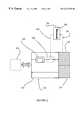
- FIG. 1depicts a significant problem with the conventional Infrared-enabled appliance; it is an illustration of such an appliance 10 .
- the typical Ir-enabled appliance 10includes an infrared transceiver system 12 that is, for the purposes of this discussion, provided electrical power 14 by a power supply means 16 , such as an internal battery or an external cable.
- a power supply means 16such as an internal battery or an external cable.
- Within the transceiver system 12there are typically at least one infrared transmitter 18 (or transmitter array) and at least one receiver 20 (or receiver array).
- a transmit data signal 26is essentially a string of “power-off's” and “power-on's”, which represent digital zero's and one's, respectfully.
- a “power-on”causes the transmitter 18 to emit an infrared signal 28 . While transmitting normally, these “power-on's” and “power-off's” are of very short duration—on the order of less than one-tenth (0.1) second each.
- the appliance 10may direct or otherwise cause the power 14 to be energized to the transceiver 12 , and more specifically, to create a “power-on” to the transmitter 18 for a substantial period of time. Furthermore, it is somewhat common for the CPU 22 to “lock up” or otherwise go into a “hang mode” during a variety of operations (or error conditions)—sometimes this, too can create a “power-on” condition in the transmitter 18 .
- the problem addressed by the present inventionrelates to the damage incurred by the transmitter 18 when the appliance is undergoing one of these power-up modes. It has been observed that the transmitter diode temperature 28 (represented by the thermometer here) of the typical infrared transmitter 18 will reach dangerously high levels if the transmit data signal 26 to the transmitter 18 is left in the “power-on” condition for periods in excess of 5 to 10 seconds. After being subjected to these high temperatures 22 , particularly on a repeated basis, the typical transmitter 18 will fail due to thermal burn-out. What is needed is an improved transceiver system and method to prevent transmitter over-temp and subsequent failure due to prolonged “power-up” conditions.
- the preferred method and systemwill detect when the Ir transmitter(s) are approaching or have achieved an overtemperature condition. Once an overtemperature condition is detected, the preferred system should interrupt electrical transmit power to said transmitter until such time as said overtemperature condition is dissipated. It is a further object that the system and method send a standby signal to the Central Processing Unit or communications controller when an overtemperature condition is detected. It is a still further object that the system emit status signals perceptible to the human senses when normal and abnormal temperature conditions are detected in the transmitter.
- FIG. 1is an illustration of a prior Infrared-enabled appliance having a conventional Infrared transceiver system
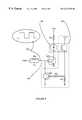
- FIG. 2is an illustration of the improved Infrared transceiver system of the present invention, including a temperature sensing and control system;
- FIG. 3is an illustration of the system of FIG. 2, depicting the temperature sensing and control system under normal operating temperatures;
- FIGS. 4A and 4Bare illustrations of embodiments of the present invention that will provide additional safety and reliability benefits.
- FIG. 5is a preferred circuit diagram of a conventional Infrared transmitting paired with the temperature sensing and control system of the present invention.
- FIG. 2is an illustration of the improved Infrared transceiver system 30 of the present invention, including a temperature sensing and control means 32 .
- the temperature sensing and control means 32is thermally coupled to the Ir transmitter 18 , such that a temperature signal 34 , proportional to the temperature of the transmitter 18 , is detected by it.
- the temperature sensing and control means 32might be provided by a variety of conventional systems and devices, including arrangements including thermocouples, thermistors and simple temperature switches, among others.
- the sensing and control means 32When the temperature sensing and control means 32 receives a temperature signal 34 that correlates to an overtemperature condition 36 within the Ir transmitter 18 , the sensing and control means 32 sends a deactivate signal 38 to a switch means 40 .
- the switch means 40is in circuit between the communications controller 24 and the Ir transmitter 18 ; deactivating the switch means 40 removes the transmit signal 26 from the Ir transmitter 18 . In operation, then, when operating conditions cause the Ir transmitter 18 to reach a dangerously high temperature, it's drive current is disconnected from the transmitter 18 before burn-out temperature is reached.
- the preferred switch means 40may be a number of conventional circuits and devices, including mechanical, electromechanical and/or electronic components that are capable of cycling from a closed to an open condition in response to an external control signal emanating from the temperature sensing and control means 32 .
- the switch means 40 or temperature sensing and control means 32may send a “temperature standby” signal 44 to the Central Processing Unit (or communications controller). Upon receiving the “temperature standby” signal 44 , the CPU and/or communications controller will stop sending data for transmission by the transceiver system 30 . Once the Ir transmitter 18 has reached a safe temperature, the switch means 40 or temperature sensing and control means 32 will send a “resume transmissions” signal 46 to the CPU and/or communications controller 24 , after receipt of which, the sending of data for Ir transmission will resume.
- FIG. 4Bdepicts yet another embodiment, wherein the temperature sensing and control means 32 may include an external visual 48 , audible 50 , and/or other warning signal for notifying the user that the Ir transmitter 18 has been deactivated to prevent temperature damage to the device and system.
- the sensing and control means 32might issue another external or internal alert when the Ir transmitter 18 has actually been damaged and therefore requires replacement.
- the sensing and control means 32could be capable of recording and internally trending the temperature “fatigue” experienced by the Ir transmitter due to repetitive cycling to high temperatures—in this manner, burn-out failure could be predicted by the improved sensing and control means 32 so that the transmitter 18 could be replaced before a failure actually happens.
- FIG. 5is a preferred circuit diagram of a conventional Infrared transmitter 18 paired with the temperature sensing and control system 32 of the present invention.
- the temperature sensing and control means 32comprises a temperature dependent drive device that is tightly thermally coupled to the transmitter 18 .
- the drive voltage to Q 2is increased, thereby removing the base drive voltage to Q 1 of the switch means 40 , and causing the input power (of the transmit data signal 26 ) to be lowered or totally interrupted before the transmitter 18 is damaged.
Landscapes
- Physics & Mathematics (AREA)
- Electromagnetism (AREA)
- Engineering & Computer Science (AREA)
- Computer Networks & Wireless Communication (AREA)
- Signal Processing (AREA)
- Selective Calling Equipment (AREA)
Abstract
Description
Claims (15)
Priority Applications (2)
| Application Number | Priority Date | Filing Date | Title |
|---|---|---|---|
| US09/143,150US6317235B1 (en) | 1998-08-28 | 1998-08-28 | Method and system for preventing burn-out of infrared transmitter diodes |
| PCT/US1999/019368WO2000013346A1 (en) | 1998-08-28 | 1999-08-23 | Method and system for preventing burn-out of infrared transmitter diodes |
Applications Claiming Priority (1)
| Application Number | Priority Date | Filing Date | Title |
|---|---|---|---|
| US09/143,150US6317235B1 (en) | 1998-08-28 | 1998-08-28 | Method and system for preventing burn-out of infrared transmitter diodes |
Publications (1)
| Publication Number | Publication Date |
|---|---|
| US6317235B1true US6317235B1 (en) | 2001-11-13 |
Family
ID=22502811
Family Applications (1)
| Application Number | Title | Priority Date | Filing Date |
|---|---|---|---|
| US09/143,150Expired - LifetimeUS6317235B1 (en) | 1998-08-28 | 1998-08-28 | Method and system for preventing burn-out of infrared transmitter diodes |
Country Status (2)
| Country | Link |
|---|---|
| US (1) | US6317235B1 (en) |
| WO (1) | WO2000013346A1 (en) |
Cited By (7)
| Publication number | Priority date | Publication date | Assignee | Title |
|---|---|---|---|---|
| WO2003003619A3 (en)* | 2001-06-29 | 2003-04-10 | Xanoptix Inc | Redundant optical device array |
| US6731665B2 (en) | 2001-06-29 | 2004-05-04 | Xanoptix Inc. | Laser arrays for high power fiber amplifier pumps |
| US6775308B2 (en) | 2001-06-29 | 2004-08-10 | Xanoptix, Inc. | Multi-wavelength semiconductor laser arrays and applications thereof |
| US20060118539A1 (en)* | 2004-12-02 | 2006-06-08 | Motorola, Inc. | System and method for thermal management in a device |
| US20060120807A1 (en)* | 2004-12-02 | 2006-06-08 | Myers Randal B | Method to produce landfill daily cover from sewer sludge and MSW |
| US8948222B1 (en) | 2013-09-30 | 2015-02-03 | Jds Uniphase Corporation | Laser diode light source |
| US20200366438A1 (en)* | 2017-06-19 | 2020-11-19 | Telefonaktiebolaget Lm Ericsson (Publ) | Adaptation Of On/Off Mask For NR With Different Numerologies |
Citations (8)
| Publication number | Priority date | Publication date | Assignee | Title |
|---|---|---|---|---|
| US5073838A (en)* | 1989-12-04 | 1991-12-17 | Ncr Corporation | Method and apparatus for preventing damage to a temperature-sensitive semiconductor device |
| US5118964A (en)* | 1990-09-26 | 1992-06-02 | At&T Bell Laboratories | Thermo-electric temperature control arrangement for laser apparatus |
| US5379145A (en)* | 1989-12-01 | 1995-01-03 | Scientific-Atlanta, Inc. | Laser transmitter for light wave (fiber optic) communication espectially of AM modulated CATV signals having means . . . against damage |
| US5602860A (en)* | 1995-04-19 | 1997-02-11 | Optelecom, Inc. | Laser thermal control using thermoelectric cooler |
| US5663823A (en)* | 1995-05-16 | 1997-09-02 | Kabushiki Kaisha Toshiba | Optical transmission system, optical transmission module, and an optical modulator |
| US5786921A (en)* | 1994-08-15 | 1998-07-28 | Actisys Corporation | Infrared communication device for multistandard operations |
| US5844928A (en)* | 1996-02-27 | 1998-12-01 | Lucent Technologies, Inc. | Laser driver with temperature sensor on an integrated circuit |
| US5978395A (en)* | 1996-01-10 | 1999-11-02 | Nec Corporation | Light transmitting apparatus |
Family Cites Families (1)
| Publication number | Priority date | Publication date | Assignee | Title |
|---|---|---|---|---|
| JPS5763879A (en)* | 1980-10-06 | 1982-04-17 | Ricoh Co Ltd | Output stabilizing method for semiconductor laser device |
- 1998
- 1998-08-28USUS09/143,150patent/US6317235B1/ennot_activeExpired - Lifetime
- 1999
- 1999-08-23WOPCT/US1999/019368patent/WO2000013346A1/enactiveApplication Filing
Patent Citations (8)
| Publication number | Priority date | Publication date | Assignee | Title |
|---|---|---|---|---|
| US5379145A (en)* | 1989-12-01 | 1995-01-03 | Scientific-Atlanta, Inc. | Laser transmitter for light wave (fiber optic) communication espectially of AM modulated CATV signals having means . . . against damage |
| US5073838A (en)* | 1989-12-04 | 1991-12-17 | Ncr Corporation | Method and apparatus for preventing damage to a temperature-sensitive semiconductor device |
| US5118964A (en)* | 1990-09-26 | 1992-06-02 | At&T Bell Laboratories | Thermo-electric temperature control arrangement for laser apparatus |
| US5786921A (en)* | 1994-08-15 | 1998-07-28 | Actisys Corporation | Infrared communication device for multistandard operations |
| US5602860A (en)* | 1995-04-19 | 1997-02-11 | Optelecom, Inc. | Laser thermal control using thermoelectric cooler |
| US5663823A (en)* | 1995-05-16 | 1997-09-02 | Kabushiki Kaisha Toshiba | Optical transmission system, optical transmission module, and an optical modulator |
| US5978395A (en)* | 1996-01-10 | 1999-11-02 | Nec Corporation | Light transmitting apparatus |
| US5844928A (en)* | 1996-02-27 | 1998-12-01 | Lucent Technologies, Inc. | Laser driver with temperature sensor on an integrated circuit |
Cited By (9)
| Publication number | Priority date | Publication date | Assignee | Title |
|---|---|---|---|---|
| WO2003003619A3 (en)* | 2001-06-29 | 2003-04-10 | Xanoptix Inc | Redundant optical device array |
| US6731665B2 (en) | 2001-06-29 | 2004-05-04 | Xanoptix Inc. | Laser arrays for high power fiber amplifier pumps |
| US6775308B2 (en) | 2001-06-29 | 2004-08-10 | Xanoptix, Inc. | Multi-wavelength semiconductor laser arrays and applications thereof |
| US7831151B2 (en) | 2001-06-29 | 2010-11-09 | John Trezza | Redundant optical device array |
| US20060118539A1 (en)* | 2004-12-02 | 2006-06-08 | Motorola, Inc. | System and method for thermal management in a device |
| US20060120807A1 (en)* | 2004-12-02 | 2006-06-08 | Myers Randal B | Method to produce landfill daily cover from sewer sludge and MSW |
| US8948222B1 (en) | 2013-09-30 | 2015-02-03 | Jds Uniphase Corporation | Laser diode light source |
| US20200366438A1 (en)* | 2017-06-19 | 2020-11-19 | Telefonaktiebolaget Lm Ericsson (Publ) | Adaptation Of On/Off Mask For NR With Different Numerologies |
| US11502801B2 (en)* | 2017-06-19 | 2022-11-15 | Telefonaktiebolaget Lm Ericsson (Publ) | Adaptation of ON/OFF mask for NR with different numerologies |
Also Published As
| Publication number | Publication date |
|---|---|
| WO2000013346A1 (en) | 2000-03-09 |
Similar Documents
| Publication | Publication Date | Title |
|---|---|---|
| US5835885A (en) | Over temperature protection method and device for a central processing unit | |
| US6084522A (en) | Temperature sensing wireless smoke detector | |
| JPH10293627A (en) | Computer system having thermosensitive unit containing double voltage source | |
| US6317235B1 (en) | Method and system for preventing burn-out of infrared transmitter diodes | |
| JP2003018883A (en) | Fan protection device | |
| US6163087A (en) | Power supplying system with a delayed closing device for delayed closing of a heat-dissipating fan | |
| US8403648B2 (en) | Compressor control device and method for controlling a compressor | |
| US7458781B2 (en) | Radiation fan driving apparatus | |
| EP1378068A2 (en) | Method for avoiding peak temperatures in communication devices | |
| US20060098368A1 (en) | Auto adjustment of over current protection in degraded mode | |
| US6222716B1 (en) | Power line protection devices and methods for providing overload protection to multiple outputs | |
| JP4254703B2 (en) | Inductive load drive | |
| KR100565482B1 (en) | Heat generating system of internet refrigerator and its operation method | |
| JP3607490B2 (en) | Optical coupling device | |
| JPH04326211A (en) | Thermal protection system for ratio communication equipment | |
| KR0163704B1 (en) | Heat sensoring device of microcontroller chip | |
| CN100380075C (en) | Heating sensing system for electric refrigerator via internet and its working method | |
| US20060195699A1 (en) | Power saving and system security method for computer system | |
| CN221378594U (en) | Over-temperature protection device for main board | |
| GB2400453A (en) | A remote protection system for disabling electrical equipment. | |
| EP2347636A1 (en) | Method and apparatus for controlling an illumination system in a temperature controlled environment | |
| JP2775064B2 (en) | Method and system for detecting disconnection of sensor line in fire monitoring system using multiplex transmission | |
| CN107491008A (en) | Wearable device | |
| KR940001421Y1 (en) | Combustion state detection circuit | |
| KR20020067142A (en) | Computer system for sensing inferior join cpu with heat sink and method thereof |
Legal Events
| Date | Code | Title | Description |
|---|---|---|---|
| AS | Assignment | Owner name:CALIBRE, INC., CALIFORNIA Free format text:ASSIGNMENT OF ASSIGNORS INTEREST;ASSIGNOR:HAMILTON, T. ALLAN;REEL/FRAME:009429/0972 Effective date:19980729 | |
| AS | Assignment | Owner name:ZILOG, INC., CALIFORNIA Free format text:ASSIGNMENT OF ASSIGNORS INTEREST;ASSIGNOR:CALIBRE, INC.;REEL/FRAME:011743/0946 Effective date:20000730 | |
| STCF | Information on status: patent grant | Free format text:PATENTED CASE | |
| FPAY | Fee payment | Year of fee payment:4 | |
| FEPP | Fee payment procedure | Free format text:PAT HOLDER NO LONGER CLAIMS SMALL ENTITY STATUS, ENTITY STATUS SET TO UNDISCOUNTED (ORIGINAL EVENT CODE: STOL); ENTITY STATUS OF PATENT OWNER: LARGE ENTITY | |
| REFU | Refund | Free format text:REFUND - SURCHARGE, PETITION TO ACCEPT PYMT AFTER EXP, UNINTENTIONAL (ORIGINAL EVENT CODE: R2551); ENTITY STATUS OF PATENT OWNER: LARGE ENTITY | |
| FPAY | Fee payment | Year of fee payment:8 | |
| AS | Assignment | Owner name:IXYS CH GMBH, SWITZERLAND Free format text:ASSIGNMENT OF ASSIGNORS INTEREST;ASSIGNOR:ZILOG, INC.;REEL/FRAME:024964/0132 Effective date:20100217 | |
| FPAY | Fee payment | Year of fee payment:12 | |
| AS | Assignment | Owner name:IXYS INTL LIMITED, CAYMAN ISLANDS Free format text:ASSIGNMENT OF ASSIGNORS INTEREST;ASSIGNOR:IXYS CH GMBH;REEL/FRAME:035665/0810 Effective date:20150515 |