US6317044B1 - Inventoriable object control and tracking system - Google Patents
Inventoriable object control and tracking systemDownload PDFInfo
- Publication number
- US6317044B1 US6317044B1US09/389,820US38982099AUS6317044B1US 6317044 B1US6317044 B1US 6317044B1US 38982099 AUS38982099 AUS 38982099AUS 6317044 B1US6317044 B1US 6317044B1
- Authority
- US
- United States
- Prior art keywords
- tag
- tags
- drawer
- slots
- tracking system
- Prior art date
- Legal status (The legal status is an assumption and is not a legal conclusion. Google has not performed a legal analysis and makes no representation as to the accuracy of the status listed.)
- Expired - Lifetime
Links
Images


Classifications
- G—PHYSICS
- G07—CHECKING-DEVICES
- G07C—TIME OR ATTENDANCE REGISTERS; REGISTERING OR INDICATING THE WORKING OF MACHINES; GENERATING RANDOM NUMBERS; VOTING OR LOTTERY APPARATUS; ARRANGEMENTS, SYSTEMS OR APPARATUS FOR CHECKING NOT PROVIDED FOR ELSEWHERE
- G07C9/00—Individual registration on entry or exit
- G07C9/00174—Electronically operated locks; Circuits therefor; Nonmechanical keys therefor, e.g. passive or active electrical keys or other data carriers without mechanical keys
- G07C9/00896—Electronically operated locks; Circuits therefor; Nonmechanical keys therefor, e.g. passive or active electrical keys or other data carriers without mechanical keys specially adapted for particular uses
- G—PHYSICS
- G07—CHECKING-DEVICES
- G07F—COIN-FREED OR LIKE APPARATUS
- G07F11/00—Coin-freed apparatus for dispensing, or the like, discrete articles
- G07F11/62—Coin-freed apparatus for dispensing, or the like, discrete articles in which the articles are stored in compartments in fixed receptacles
- G—PHYSICS
- G07—CHECKING-DEVICES
- G07F—COIN-FREED OR LIKE APPARATUS
- G07F9/00—Details other than those peculiar to special kinds or types of apparatus
- G07F9/02—Devices for alarm or indication, e.g. when empty; Advertising arrangements in coin-freed apparatus
- G07F9/026—Devices for alarm or indication, e.g. when empty; Advertising arrangements in coin-freed apparatus for alarm, monitoring and auditing in vending machines or means for indication, e.g. when empty
- G—PHYSICS
- G08—SIGNALLING
- G08B—SIGNALLING OR CALLING SYSTEMS; ORDER TELEGRAPHS; ALARM SYSTEMS
- G08B13/00—Burglar, theft or intruder alarms
- G08B13/02—Mechanical actuation
- G08B13/14—Mechanical actuation by lifting or attempted removal of hand-portable articles
- G08B13/1427—Mechanical actuation by lifting or attempted removal of hand-portable articles with transmitter-receiver for distance detection
- G—PHYSICS
- G07—CHECKING-DEVICES
- G07C—TIME OR ATTENDANCE REGISTERS; REGISTERING OR INDICATING THE WORKING OF MACHINES; GENERATING RANDOM NUMBERS; VOTING OR LOTTERY APPARATUS; ARRANGEMENTS, SYSTEMS OR APPARATUS FOR CHECKING NOT PROVIDED FOR ELSEWHERE
- G07C9/00—Individual registration on entry or exit
- G07C9/00174—Electronically operated locks; Circuits therefor; Nonmechanical keys therefor, e.g. passive or active electrical keys or other data carriers without mechanical keys
- G07C9/00896—Electronically operated locks; Circuits therefor; Nonmechanical keys therefor, e.g. passive or active electrical keys or other data carriers without mechanical keys specially adapted for particular uses
- G07C2009/00936—Electronically operated locks; Circuits therefor; Nonmechanical keys therefor, e.g. passive or active electrical keys or other data carriers without mechanical keys specially adapted for particular uses for key cabinets
Definitions
- This inventionrelates generally to the field of controlling and tracking access to various types of objects, and in its most preferred embodiments, to integrating an electronic identification code and tracking system to continually inventory a plurality of objects.
- control over the removal and re-insertion of an object stored in the containerhas been maintained by employing manual procedural methods such as issuing keys for the container to only select individuals (i.e., usually managers or supervisors), requiring an employee or maintenance worker to request that a manager or supervisor provide access to the container for removal and/or re-insertion of objects from/to the container, and requiring the employee or worker to sign for any object removed and/or re-inserted from/to the container.
- individualsi.e., usually managers or supervisors
- requiring an employee or maintenance worker to request that a manager or supervisor provide access to the container for removal and/or re-insertion of objects from/to the containerand requiring the employee or worker to sign for any object removed and/or re-inserted from/to the container.
- many automobile dealersplace the keys to vehicles on their lot inside a locked box.
- the customer's salespersonrequests that a manager open the box so that the salesperson can remove the keys to the vehicle from the locked box.
- a salesperson or cohortmay steal a car (or items from a car) or a worker may return to an apartment complex during the night to burglarize a unit and, potentially, cause physical harm to a tenant. Additionally, by keeping a key out of the locked container for a longer period of time than necessary without the knowledge of a manager or landlord, the key may be copied or become lost by the salesperson or maintenance worker.
- the limited success and inherent problems of manual systemssuggest the need for a system which automatically controls access to and tracks the use of various types of objects.
- At least one automatic systemhas been developed and used in the past.
- the systememployed a lockable container for storing objects which were each attached to a unique assembly identified by a conventional bar-code symbol printed on a tongue of the assembly.
- the containerincorporated an enclosure and a drawer which, after unlocking, could be slidably removed or inserted into the enclosure, thereby creating relative movement between the drawer and a bar-code scanner mounted to the enclosure.
- the tongue of each assemblyextended downward through an aperture in a top panel of the drawer to enable reading of the bar-code for each assembly by the bar-code scanner whenever the drawer was moved relative to the enclosure.
- the bar-code scannerrequired relative movement between the drawer and the enclosure to function, the bar-codes associated with each object could only be read if the drawer was opened or closed. Therefore, the system had no way of detecting the presence or absence of an object unless the drawer was opened or closed, for example, by a manager or landlord. Thus, the system could not accurately track the amount of time that an object was not present in the container, nor could it determine who actually had possession of the object. Also, because the assemblies were not restrained and were therefore, prone to variable, random movement relative to the drawer and enclosure, misreads by the bar-code scanner were a continual problem requiring repeated openings and closings of the drawer to effect accurate reading of all of the bar-codes on the present assemblies.
- the present inventionincludes an inventoriable-object control and tracking system which limits access to an inventoriable-object, tracks activities performed related to the object, and automatically detects the absence of the object for an inordinate amount of time. More particularly, the present invention includes an inventory control and tracking system which couples an electronic device, having a unique identification code, to an inventoriable-object and interfaces the device to a remote controller through a novelly-designed interface to enable periodic, consistent, and accurate identification of the object's presence or absence.
- each of a plurality of inventoriable objectsis coupled to an object identification assembly having an electronic device mounted to an interface member of the assembly.
- the electronic devicestores a unique identification code which is invisible to the eye, but electronically readable upon supply of a proper sequence of signals to the electronic device.
- the systemprovides a unique, trackable identification code for each object.
- Each identification assemblyis receivable by a connector comprised of opposed, self-aligning, spring contacts having separate portions which independently deflect to insure and maintain consistent electrical interaction of the electronic device and connector.
- Each connectoris one of a plurality of connectors which are electrically attached to a backplane with one contact of each connector being electrically connected to a positive data line and the other contact of each connector being electrically connected .to a negative return line.
- the positive-connected contactsare arranged on the backplane in columns, while the negative-connected contacts are arranged on the backplane in rows, thereby defining a row and column matrix arrangement of connectors in which each connector has an associated row and column address and is independently, electrically-addressable from the other connectors of the matrix arrangement.
- the plurality of connectors and backplaneare offset relative to panel which defines a polarized slot or opening aligned with each connector (the combination of a slot, or opening, and a connector being referred to herein as a receptacle) for receipt of an object identification assembly.
- the polarized design of each slot and openingenables receipt of an object identification assembly in only one orientation, thereby insuring that an identification assembly is always properly oriented for receipt by a connector.
- the rows and columns of contactsare, in accordance with the preferred embodiments of the present invention, electrically coupled to a local controller by flexible cabling which enables relative motion between the backplane and the local controller should such relative motion be necessary in a particular embodiment.
- the local controllerincludes an electrically addressable switch which controls the supply of electrical power to most of the electronic components of the local controller.
- the addressable switchhas a unique address and must electronically receive its address before it allows the supply of electrical power to the remaining electronic components of the local controller, thereby minimizing the opportunity for unauthorized operation of the local controller.
- the local controlleralso includes row and column address decoding and access circuitry which enables the unique identification of and independent interaction between a remote controller and each of the plurality of connectors to allow reading of the identification code of an electronic device by the remote controller when the electronic device resides in a connector.
- the remote controllerconnects electrically to and communicates with the local controller, in a bidirectional manner, using a parallel computer interface commonly employed for communication between computers and printers. Signals, including output data from the electrical devices, are transferred through the parallel interface in a serial protocol instead of the parallel protocol typically employed for communication between most computers and printers.
- the remote controllerincludes a central processing unit and a storage device to enable receipt and storage of data from the local controller which is related to the presence or absence of an object identification assembly and, hence, an object from the backplane.
- a backplane and top panelare rigidly positioned within a cavity of a drawer which is slidably mounted within a surrounding enclosure.
- the top panelis oriented to enable user access for the insertion and removal of object identification assemblies when the drawer is extended in an open position from within the enclosure.
- a flexible cableattaches electrically to the rear of the backplane and extends forward beneath the backplane where it connects to a local controller which is mounted to the enclosure. The flexing and routing of the cable enable motion of the drawer relative to the local controller without binding of the cable.
- the local controllerconnects electrically to a face plate connector, substantially similar to those mounted to the backplane, which resides in a face plate of the drawer.
- the face plate connectoris accessible from the front of the drawer at all times for receipt of a personal identification assembly (i.e., an object identification assembly without a coupled inventoriable-object for use by a user to provide a unique identification code for the user) from a user.
- the local controlleralso connects to an electrically-actuated lock which is located at the rear of the enclosure cavity for interaction with and securing of the drawer when the drawer is oriented in a closed position within the enclosure and for release of the drawer from the enclosure in response to appropriate signals communicated to the local controller from a remote controller.
- a drawer switchalso connected to the local controller, is positioned to contact the drawer when the drawer is positioned completely within the enclosure and to indicate the position of the drawer (i.e., open or closed) to the remote controller.
- the local controlleris additionally connected, via parallel ribbon cabling, to a pair of pass-through parallel port connectors (also referred to herein as data communication interfaces) mounted to and extending through the rear of the enclosure.
- a pair of pass-through parallel port connectorsalso referred to herein as data communication interfaces mounted to and extending through the rear of the enclosure.
- One of the pass-through parallel port connectorsreceives a parallel cable extending to the enclosure from a parallel port of the remote controller, while the other pass-through parallel port connector receives a parallel cable extending from the enclosure to a printer.
- the parallel cable(also referred to herein as a communication link) extending between the enclosure and remote controller defines a plurality of parallel communication paths which enable the remote controller to communicate with the local controller and the various components connected to or a part of the local controller including, for example, the connectors, the addressable switch, the face plate connector, the electrically-actuated lock, and the drawer switch.
- multiple enclosuresare daisy-chainable together using parallel cables, serving as data communication links, which extend between the pass-through parallel ports (or data communication interfaces) of each enclosure, thereby causing the parallel ports and cables to function as a parallel bus.
- the enclosures of this alternate embodimentare substantially similar to the enclosure of the first preferred embodiment and, therefore, include components and elements substantially similar to those of the enclosure of the first preferred embodiment.
- the local controller of each enclosure of the alternate embodimentincludes an addressable switch having a unique address which enables an addressable switch and, hence, its local controller to be uniquely selected from those of other enclosures for operation by and communication with a remote controller.
- each inventoriable-object of a first plurality of inventoriable-objectsis coupled to an object identification assembly of a first plurality of object identification assemblies and each inventoriable-object of a second plurality of inventoriable-objects (different than those of the first plurality of inventoriable-objects and including, for example, a vehicle license plate) is coupled to an object identification assembly of a second plurality of object identification assemblies (different than those of the first plurality of object identification assemblies).
- a first backplane and a first plurality of connectors(substantially similar to those of the first preferred embodiment), attached to the first backplane and defining a row and column matrix arrangement of connectors, are positioned within a cavity of a drawer which is slidably mounted within a surrounding enclosure.
- the first backplane and first plurality of connectorsreside near the front of the drawer's cavity for receipt of object identification assemblies of the first plurality of object identification assemblies.
- a second backplane and a second plurality of connectors(substantially similar to those of the first preferred embodiment), attached to the second backplane and defining a row and column matrix arrangement having a single row and multiple columns of connectors, are positioned near the rear of the drawer's cavity and receive object identification assemblies of the second plurality of object identification assemblies.
- the second plurality of connectors and second backplaneare offset from a panel having polarized openings which are each aligned with a connector of the second plurality of connectors.
- Flexible cablesconnect the first and second pluralities of connectors to a local controller and, hence, to a remote controller which are substantially similar in structure and function to the local and remote controllers of the first preferred embodiment of the present invention.
- the above-described connectorsreceive a plurality of object identification assemblies with each connector receiving one object identification assembly which extends through an aligned, polarized slot or opening in a panel.
- the remote controllerexecutes a plurality of software routines which communicate bi-directionally and serially with the local controller, via the data communication links and interfaces, to control access to and tracking of the plurality (or pluralities) of object identification assemblies received by the backplane (or backplanes).
- the software routinesprovide a plurality of functions including for example, but not limited to: addressing/selecting a local controller's addressable switch to cause the local controller to become active (i.e., power up the remainder of its electronic components); reading the unique identification code stored by an electronic device of a personal identification assembly which is received by a face plate connector of an enclosure's drawer; signaling a local controller; and its electrically-actuated lock, to release its drawer from its enclosure; requesting a local controller to return data which indicates the current position of its connected drawer switch and, hence, the position of a drawer; and, causing a local controller, after being activated, to uniquely address and read the identification code of the electronic device of each object identification assembly present in a connector of a row and column matrix of connectors coupled to the local controller.
- a local controllerWhen directed by a remote controller to uniquely address and read the identification codes of the present electronic devices, a local controller outputs each identification code to the remote controller for further processing, including, for instance, logging of all removals and insertions (or replacements) of object identification assemblies (and, hence, inventoriable-objects), determination of the current location (slot or opening, and drawer) of each object identification assembly, and periodic checking to determine whether or not an object identification assembly is absent from the connectors of a backplane and if so, whether or not the object identification assembly has been absent for an inordinate amount of time.
- the remote controllermay request that a local controller read and output the identification codes of any electronic devices present in a connector matrix at any time (whether or not its associated drawer is open, partially open, or closed relative to its enclosure) and without requiring any movement, relative or absolute, of the inventoriable-objects, their coupled object identification assemblies, or their corresponding connectors, drawers, or enclosures.
- a face plate connector of a drawerreceives a personal identification assembly in response to a prompt issued to a user and a remote controller, functioning in cooperation with the drawer's local controller, reads the identification code stored by the electronic device of the personal identification assembly.
- the remote controllerUpon receiving a password from the user attempting to gain access to the system and verifying that the password is valid for the personal identification assembly received by the face plate connector, the remote controller prompts the user to identify the type of activity that the user wishes to perform on an object identification assembly (for example, removal of an object identification assembly from a drawer or insertion of an object identification assembly into a drawer).
- the remote controllerprompts for and receives the identity of an object desired by a user for removal and then determines which enclosure, of a plurality of enclosures (if more than one enclosure is present in the system), stores the object identification assembly which is coupled to the object desired by the user.
- the remote controllernext displays the slot or opening location of the object identification assembly (and, hence, the location of the desired object) relative to the other slots and/or openings in the enclosure's drawer on a display screen shown by the system's video monitor and causes the enclosure's drawer electrically-actuated lock to be released by signaling the enclosure's local controller to operate the lock mechanism.
- the remote controllerprompts for and receives input from the user which identifies the type of object to be received by a drawer.
- the remote controllerdetermines the location of one or more empty slots or openings in an enclosure, suitable for the type of object to be received, and displays the locations on a display screen shown on the system's video monitor.
- the remote controllersubsequently signals the appropriate local controller, via a data communication link and interface, to cause the electrically-actuated lock of the corresponding enclosure to operate, thereby releasing the enclosure's drawer for insertion of the object by the user.
- the remote controlleracting in conjunction with the local controller and in accordance with the preferred method of the present invention, repeatedly scans the backplane connectors to identify which object identification assemblies have been removed or replaced and logs the identification code of the removed or replaced assemblies along with the date/time, location of the assemblies, and the identification code read from the personal identification assembly received by the face plate connector (i.e., thereby identifying the user accessing the drawer).
- the remote controlleralso monitors the drawer switch to determine whether or not the drawer has been open for an excessive amount of time. If so, the remote controller sounds an alarm to alert someone to close the drawer. If not, the remote controller continues to scan the backplane connectors and continues to monitor the drawer switch until the remote controller detects that the drawer has been closed.
- the remote controllerperforms a final scan of the backplane connectors to identify and log object identification assemblies which are present in the drawer.
- the remote controllerthen processes the identification codes of the present object identification assemblies to make a final determination of which assemblies have been removed or inserted while the drawer was open, a determination as to which user performed the removal or insertion, and a determination of the date and time which identifies when the assemblies were removed from or inserted into the drawer.
- the remote controllersubsequently determines whether or not any assemblies have been removed from the system for an excessive amount of time and, if so, issues an alarm to call attention to the missing assemblies.
- an object of the present inventionis to control access to and monitor activities related to a plurality of inventoriable-objects.
- Another object of the present inventionis to detect the presence or absence of an object.
- Still another object of the present inventionis to detect the presence or absence of an object without movement of the object or an interface member coupled to the object.
- Still another object of the present inventionis to detect the presence or absence of an object without movement of the object, or an interface member coupled to the object, relative to another component.
- Still another object of the present inventionis to detect the presence or absence of an object at any time.
- Still another object of the present inventionis to detect the presence or absence of an object with the object's receiver in any position or orientation.
- Still another object of the present inventionis to rapidly locate a particular object.
- Still another object of the present inventionis to display the location of a particular object.
- Still another object of the present inventionis to suggest a storage location for the return of an object.
- Still another object of the present inventionis to log the removal and replacement of objects by the object's identification code, the user's identification code, and the date/time of removal and replacement.
- Still another object of the present inventionis to identify objects which have been removed for an excessive period of time.
- Still another object of the present inventionis to uniquely identify an object with an identification code which is difficult to copy.
- Still another object of the present inventionis to attach an object to an assembly which enables tracking of the object.
- Still another object of the present inventionis to interface an electronic device, having a unique identification code, and a connector to enable accurate, repeatable reading of the identification code from the electronic device.
- Still another object of the present inventionis to form a connector, for receipt of an electronic device, from opposed contacts having portions which deflect independently to insure electrical connection with the electronic device.
- Still another object of the present inventionis to form a row and column matrix of contacts from a plurality of two-contact connectors by electrically connecting a first contact of each connector to a row of the matrix and a second contact of each connector to a column of the matrix.
- Still another object of the present inventionis to individually address each connector to determine whether or not an identification assembly and, hence, an object is present.
- Still another object of the present inventionis to retrieve the identification code from each of a plurality of identification assemblies.
- Still another object of the present inventionis to enable bidirectional, serial communication between a remote controller and an identification assembly using a parallel communication path.
- Still another object of the present inventionis to control access to a plurality of objects by storing them in an enclosure and controlling access to the enclosure.
- Still another object of the present inventionis to identify a user who removes or replaces an object from the enclosure.
- Still another object of the present inventionis to supply a unique address to a local controller in order to activate and enable operation of the local controller.
- Still another object of the present inventionis to determine whether or not a drawer resides fully within an enclosure.
- Still another object of the present inventionis to release a drawer from an enclosure by operating an electrically-actuated lock.
- Still another object of the present inventionis to enable daisy-chaining of a plurality of enclosures in a parallel bus arrangement.
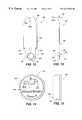
- FIG. 1is a front, perspective, pictorial representation of an inventoriable-object control and tracking system in accordance with the first preferred embodiment of the present invention.
- FIG. 2is a back, schematic view of the inventoriable-object control and tracking system of FIG. 1 .
- FIG. 3is a front, perspective, pictorial representation of an inventoriable-object control and tracking system in accordance with an alternate embodiment of the present invention.
- FIG. 4is an isolated, front, perspective, schematic view of an enclosure and drawer of the inventoriable-object control and tracking system of FIG. 1 .
- FIG. 5is an isolated, top, plan view of an assembly retaining structure of the drawer of FIG. 4 .
- FIG. 6is an isolated, top, plan view of a slot of the assembly retaining structure of FIG. 5 .
- FIG. 7is a partial, right side view of the assembly retaining structure of FIG. 5 .
- FIG. 8is a partial, front view of the assembly retaining structure of FIG. 5 .
- FIG. 9is an isolated, front view of a contact of the assembly retaining structure of FIG. 7 and 8.
- FIG. 10is a side view of the contact of FIG. 9 .
- FIG. 11is a bottom, plan view of the contact of FIG. 9 .
- FIG. 12is an isolated, front view of an identification assembly in accordance with the first preferred embodiment of the present invention.
- FIG. 13is an isolated, side view of the identification assembly of FIG. 12 .
- FIG. 14is a front view of the electronic device of FIG. 12 .
- FIG. 15is a side view of the electronic device of FIG. 14 .
- FIG. 16is a top, plan, schematic view of the backplane of the assembly retaining structure of FIGS. 7 and 8.
- FIG. 17is a side, pictorial view of the enclosure and drawer of FIG. 4, where the drawer is fully-inserted into the enclosure.
- FIG. 18is an isolated, front view of a utility panel of the enclosure of FIG. 4 .
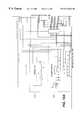
- FIG. 19is an electrical schematic of the local controller of FIG. 17 .
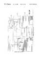
- FIG. 20is an electrical schematic of the parallel port section of FIG. 19 .
- FIG. 21is an electrical schematic of the receive direction section of FIG. 19 .
- FIG. 22is an electrical schematic of the receive/transmit data section of FIG. 19 .
- FIG. 23is an electrical schematic of the enable section of FIG. 19 .
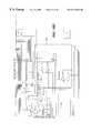
- FIG. 24is an electrical schematic of the matrix communication section of FIG. 19 .
- FIG. 25is an electrical schematic of the receive/transmit ID slot data section of FIG. 19
- FIG. 26is an electrical schematic of the transmit enclosure position section of FIG. 19
- FIG. 27is an electrical schematic of the lock driver section of FIG. 19 .
- FIG. 28is an electrical schematic of the LED driver section of FIG. 19 .
- FIG. 29is an electrical schematic of the power supply section of FIG. 19 .
- FIG. 30is an isolated, front, perspective, schematic view of an enclosure and drawer of an inventoriable-object control and tracking system in accordance with a second referred embodiment of the present invention.
- FIG. 31is an isolated, front, elevational view of an opening of the second assembly retaining structure of FIG. 30 .
- FIG. 32is an isolated, right side, elevational view of the channel member of the drawer of FIG. 30 .
- FIG. 33is a front, perspective view of an object identification assembly of a second plurality of object identification assemblies of the second preferred embodiment of the present invention.
- FIG. 34is a front, elevational view of the interface member of the object identification assembly of FIG. 33 .
- FIG. 35is a top, plan view of the interface member of FIG. 33 .
- FIG. 36is a partial, top, plan view of a second assembly retaining structure of FIG. 30 .
- FIG. 37is a flowchart representation of a preferred method in accordance with a preferred embodiment of the present invention.
- FIGS. 1 and 2an inventory control and tracking system 50 , in accordance with the first preferred embodiment of the present invention, is displayed in FIGS. 1 and 2.
- the inventory control and tracking system 50comprises an inventoriable-object storage unit 52 which is electronically interposed between a remote controller 54 and a printer 56 .
- An example of a remote controller 54is an IBM-compatible personal computer having a central processing unit, a hard disk drive, a random access memory, a keyboard, a video interface, and a parallel communications port 58 (or data communication interface 58 ).
- a video monitor 60resides atop the remote controller 54 and receives video data for display to system users.
- the components of the remote controller 54 and video monitor 60perform in accordance with their conventional functions, thereby enabling the execution of computer software routines as described below. It is understood that the scope of the present invention includes other forms of remote controllers having similar capabilities and performing similar functions.
- FIG. 2displays the rear of the remote controller 54 , the storage unit 52 , and the printer 56 and better illustrates the electronic connection of the three components than does FIG. 1 .
- the storage unit 52has a utility panel 62 and a back panel 64 which defines a cut-out 66 for receipt of electrical connectors attached to a portion of the utility panel 62 visible through the cut-out 66 .
- the utility panel 62discussed below in more detail, resides inside the storage unit 52 and against the back panel 64 .
- the utility panel 62includes bi-directional, parallel data communications ports 68 , 70 (or data communication interfaces 68 , 70 ) which are interconnected in a pin-for-pin arrangement to enable parallel communications signals supplied to port 68 to be accessed at port 70 and vice versa (e.g., configuring the ports 68 , 70 as “pass-through”,or “daisy-chainable” parallel data communications ports 68 , 70 ).
- a parallel data communication path 72(or data communication link 72 ) extends between the parallel communications port 58 of the remote controller 54 and parallel data communications port 68 of the storage unit 52 .
- the parallel data communication path 72is a conventional parallel data cable well-known to those in the computer industry.
- the parallel data communication path 72carries data signals, in a serial protocol, bi-directionally between the remote controller 54 and the storage unit 52 .
- Another parallel data communication path 74(or data communication link 74 ) extends between the pass-through, parallel data communications port 70 and a parallel data communications port 76 present at the back of the printer 56 to carry data signals, in a parallel protocol, from the remote controller 54 to the printer 56 .
- the utility panel 62also includes power supply connectors 78 , 80 which are connected together inside the storage unit 52 to allow one connector 78 to receive electrical power from a power source (not shown), while the other connector 80 supplies electrical power to an additional storage unit 52 as described below.
- a fuse holder 82 and fuse(not visible) are secured to utility panel 62 and are electrically connected to the power supply connectors 78 , 80 .
- the fuseprotects internal electronic components of the storage unit 52 against over-current conditions.
- the back panel 64also includes a key lock assembly 84 , discussed below, having an externally accessible keyway as seen in FIG. 2 .
- the key lock assembly 84enables a user, in an extreme situation, to manually override an electrically-actuated lock mechanism 218 (see FIG. 17 ).
- multiple storage units 52 ′are employed to increase the number of inventoriable objects which may be stored and tracked by the system 50 ′.
- the pass-through, parallel data communications ports 68 ′, 70 ′ (or data communication interfaces 68 ′, 70 ′) of each storage unit 52 ′are interconnected by parallel data communication paths 74 a ′, 74 b ′ (or data communication links 74 a ′, 74 b ′) to enable the remote controller 54 ′ to communicate serially, using a serial data protocol, with each storage unit 52 ′.
- the scope of the present inventionincludes various system configurations, including those configurations having a plurality of storage units 52 ′.
- FIG. 4displays an isolated, front, perspective, schematic view of a storage unit 52 in accordance with the first preferred embodiment of the present invention.
- the storage unit 52comprises an enclosure 86 having a front face 88 , a right side 90 , and a back 92 .
- the enclosure 86defines a cavity 94 which is accessible via an opening 96 defined by the front face 88 .
- the cavity 94slidably receives a drawer 98 which is shown partially extended from the cavity 94 in FIG. 4 .
- the drawer 98has a right side member 100 , a left side member 102 , a front face assembly 104 , and a back member 106 .
- the front face assembly 104has a front face plate 108 and an inset handle 110 which is flush with the front face plate 108 .
- the inset handle 110enables easy withdrawal of the drawer 98 from the enclosure 86 after release of the drawer 98 by the electrically-actuated lock mechanism 218 (see FIGS. 17 and 18 ).
- the front face plate 108defines an ID slot 112 for receipt of a user's personal identification assembly.
- a connectorsimilar to those described below, is mounted directly behind the ID slot 112 and within the front face assembly 104 for establishing electrical contact with the electronic device of a user's personal identification assembly.
- LED's 113are positioned in the front face 88 and flash when the enclosure 86 is activated as discussed below.
- the drawer 98defines a reservoir 114 which receives an assembly retaining structure 116 having a top panel 118 .
- the top panel 118defines a plurality of slots 120 , shown schematically in FIG. 4, which define a row and column matrix 122 .
- FIG. 5,a top plan view of the top panel 11 . 8 , more accurately displays the slot matrix 122 where the rows of slots 120 are labeled with letters A-O and the columns of slots 120 are labeled with numbers 1 - 16 .
- each slot 120has an outer perimeter 124 which is shaped to receive a tongue portion 184 of an object identification assembly 182 described below (see FIG. 12 ).
- FIG. 12As seen in the isolated, top plan view of FIG.
- each slot 120is symmetrical about a center lateral axis 126 , but is not symmetric about a center longitudinal axis 128 .
- the lack of symmetry about center longitudinal axis 128causes each slot 120 to be “polarized”, thereby allowing receipt of the tongue portion 184 of an object identification assembly 182 in only one orientation.
- Such polarization of each slot 120is necessary to properly orient an object identification assembly 182 , which, when present in a drawer 98 , depends through a slot 120 , for electrical interaction with a connector I 54 as described below.
- FIGS. 7 and 8A portion of the assembly retaining structure 116 , in accordance with the preferred embodiment, is shown in the right side and front partial views of FIGS. 7 and 8. The views also display an object identification assembly 182 which is received by a slot 120 of the top panel 118 of the assembly retaining structure 116 .
- the assembly retaining structure 116includes a backplane 130 positioned beneath and opposed to the top panel 118 .
- the backplane 130is held in position relative to the top panel 118 by a plurality of standoffs 132 which are periodically located between the backplane 130 and top panel 118 .
- Each standoff 132is secured to the top panel 118 by a press-in stud 134 having a head 136 which lies flush with an upper surface 138 of the top panel 118 .
- Each stud 134extends downward through a hole 140 defined by the top panel 118 and is received by a hole 142 defined by a standoff 132 .
- Each standoff 132is secured to the backplane 130 by a screw 144 having a head 146 which rests against a bottom surface 148 of the backplane 130 .
- the screw 144extends through a hole 150 defined by the backplane 130 and is received by a threaded hole 152 defined by the standoff 132 .
- the assembly retaining structure 116further comprises a plurality of connectors 154 with one connector 154 being positioned directly beneath and aligned with each slot 120 of the row and column slot matrix 122 , thereby defining a row and column matrix of connectors 156 opposed to the row and column slot matrix 122 and residing between the top panel 118 and the backplane 130 .
- FIG. 7displays two connectors 154 a,b , each being a member of a different row of the matrix of connectors 156
- FIG. 8shows the same two connectors 154 a,b , each also being a member of a different column of the matrix of connectors 156 .
- Each connector 154comprises a pair of opposed contacts 158 which are each rigidly mounted to a top surface 160 of the backplane 130 by a rivet 162 .
- the opposed contacts 158define a gap 164 between the contacts 158 for receipt of an object identification assembly 182 by connector 154 a as illustrated in FIGS. 7 and 8.
- FIGS. 9-11display left side, front, and bottom views of a single contact 158 in accordance with the preferred embodiment of the present invention.
- Each contact 154includes an upper portion 166 , a mid-portion 168 , and a base portion 170 .
- the upper portion 166is angled relative to the mid-portion 168 to enhance the reception of an object identification assembly 182 by guiding a received object identification assembly 182 toward the gap 164 defined between the contacts 158 .
- the mid-portion 168 of each contact 158is angled relative to the base portion 170 and includes a tongue 172 which is, itself, angled relative to the mid-portion 168 .
- the base portion 170resides atop and adjacent to a plated foil pad on the backplane 130 and defines a hole 174 for receipt of rivet 162 which extends through a plated-through hole 176 defined by an electrically-conductive surface of the backplane 130 .
- the plated foil pad, base portion 170 , and rivet 162are crimped together, forcing expansion of the rivet 162 to fill the plated-through hole 176 , thereby creating electrical continuity between the backplane 130 , rivet 162 , and the contact 158 .
- the base portion 170includes a tab 178 which depends from the base portion 170 and extends through a hole 180 defined by an electrically-conductive surface of the backplane 130 to aid in orienting the contact 158 relative to the backplane 130 .
- FIGS. 7 and 8display connector 154 a in receipt of an object identification assembly 182 which is more clearly illustrated in FIGS. 12 and 13.
- each object identification assembly 182comprises an inventoriable-object 202 and an interface member 183 having a tongue portion 184 , an object connection portion 186 , and a main portion 188 which extends between the tongue and object connection portions 184 , 186 .
- each interface member 183is manufactured from plastic.
- the tongue portion 184depends from the main portion 188 and, in conjunction with the main portion 188 , defines shoulders 190 which abut the top surface 138 of the top panel 118 , as seen in FIG. 7, when the tongue portion 184 is positioned within a slot 120 .
- the shoulders 190prevent excessive downward travel of the interface member 183 through a slot 120 and aid in properly positioning the interface member 183 relative to a connector 154 .
- the sides of the tongue portion 184are tapered to improve the ease of insertion into a slot 120 and to center the interface member 183 in the slot 120 .
- the tongue portion 184defines a hole 192 which receives and secures an electronic device 194 .
- the object connection portion 186defines apertures 196 (FIG. 12) and aperture 196 a receives a tubular rivet 198 which receives a blind rivet 199 .
- a washer 200which resides adjacent to the object connection portion 186 , cooperates with the blind rivet 199 to connect an inventoriable object 202 to the interface member 183 .
- the inventoriable object 202is a key, however, it is understood that the scope of the present invention encompasses the connection of a different inventoriable object selected from a variety of other types of inventoriable objects.
- the electronic device 194is shown more clearly in the front view of FIG. 14 and the right side view of FIG. 15 .
- the electronic device 194has a positive data contact 204 and a negative return contact 206 which are electrically engaged by the mid and tongue portions 168 , 172 of contacts 158 a,b , respectively, of a connector 154 .
- the electronic device 194includes a memory which permanently stores a unique identification code.
- the identification code in the electronic device 194is associated with the inventoriable object 202 .
- the identification codeis electronically readable, upon supply of the appropriate input data signals, from the electronic device 194 via its bidirectional data contact 204 .
- An electronic device 194is a DS 1990A Touch Memory Device available from Dallas Semiconductor Corporation of Dallas, Tex. and includes a 48-bit serial number (i.e., which is a unique identification code), an 8-bit CRC code, and an 8-bit family code. It is understood that the scope of the present invention includes other electronic devices having a unique, electronically-readable identification code. It is also understood that the scope of the present invention includes other electronic devices having internal random access memories and timers which are electronically-communicable therewith and which enable additional functionality beyond the identification of objects.
- the connectors 154are arranged in a row and column matrix 156 on the backplane 130 with each connector 154 having a row address and a column address.
- Each connector 154includes a contact 158 a which is electrically connected to one of a plurality of column data lines 208 and a contact 158 b which is electrically connected to one of a plurality of row return lines 210 .
- each column data line 208is a positive data line and each row return line 210 is a negative return line.
- FIG. 17displays the enclosure 86 with a drawer 98 , holding an object identification assembly 182 , fully-inserted into the cavity 94 defined by the enclosure 86 . Note that portions of the enclosure 86 , drawer 98 , and lock mounting bracket 212 have been cut-away to enable viewing of various components located inside the enclosure 86 .
- the assembly retaining structure 116resides above a local controller 214 which is mounted to the enclosure 86 in proximity to the drawer's front face assembly 104 .
- a flexible cable 216transfers electrical signals between the local controller 214 and the backplane 130 of the assembly retaining structure 116 .
- the local controller 214 and the flexible cable 216are positioned relative to the backplane 130 so that the flexible cable 216 rolls when the drawer 98 is withdrawn or inserted into the enclosure 86 .
- the local controller 214is also electrically connected to parallel data communications ports 68 , 70 (or data communication interfaces 68 , 70 ) by a ribbon cable 217 (see FIG. 18) to enable bidirectional serial communication with the remote controller 54 .
- the parallel data communications ports 68 , 70are hidden by the electrically-actuated lock mechanism 218 and lock mounting bracket 212 in FIG. 17, but are visible in FIG. 18 and are connected to the utility panel 62 which resides inside cavity 94 adjacent to the back panel 64 of the enclosure 86 .
- Power supply lines 220are electrically connected in series, via fuse holder 82 and pilot light 83 , to power supply connectors 78 , 80 (which are connected together in parallel) and to the local controller 214 .
- Lock signal lines 222 and drawer switch signal lines 224are electrically interposed between the local controller 214 and the electrically-actuated lock mechanism 218 and drawer switch 248 , respectively.
- LED lines 490 , 492electrically connect the local controller 214 to the LED's 113 .
- the electrically-actuated lock mechanism 218is held in place by lock mounting bracket 212 which is secured to the utility panel 62 .
- the lock mechanism 218includes a solenoid actuator 226 which is located in a well 228 defined by the lock mounting bracket 212 .
- the solenoid actuator 226is positioned to enable interaction of the solenoid's plunger 230 with a keeper plate 232 .
- a bearing 234pressed into the keeper plate 232 , defines a bore for receipt of a shaft 236 which is rigidly attached to the lock mounting bracket 212 and extends through the bore.
- the bearing 234enables the keeper plate 232 to rotate relative to the shaft 236 when the keeper plate 232 is rotated by linear movement of the solenoid actuator's plunger 230 .
- a biasing member(not visible) is positioned about the solenoid's plunger 230 between the solenoid actuator 226 and the keeper plate 232 .
- the keeper plate 232defines a keeper slot 238 which receives a striker rod 240 when the drawer 98 is filly-inserted into the enclosure 86 .
- the striker rod 240is rigidly mounted in a striker bracket 242 which is attached to the rear of the drawer 98 .
- the keeper slot 238rotates away from the striker rod 240 , thereby freeing the striker rod 240 and enabling the drawer 98 to be withdrawn from the enclosure 86 .
- the biasing memberforces the keeper plate 232 to return to its normally-locked position.
- key lock assembly 84includes a striker plate 244 which, when rotated by an authorized user in an extreme situation, engages the keeper plate 232 to cause rotation of the keeper plate 232 away from striker rod 240 .
- the drawer switch 248is mounted to a side of the lock mounting bracket 212 and includes a microswitch 250 and a switch actuator 252 .
- the switch actuator 252extends from the microswitch 250 adjacent to a cut-out 254 defined by the lock mounting bracket 212 .
- a portion of tile striker bracket 242resides within the cut-out 254 and engages the switch actuator 252 .
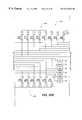
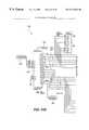
- FIG. 19displays a block diagram representation of the circuitry of the local controller 214 in accordance with the preferred embodiments of the present invention and identifies a plurality of major sections of the circuitry, including a parallel port section 300 , a receive direction section 302 , a receive/transmit data section 304 , a matrix communications section 306 , a transmit enclosure position section 308 , a receive/transmit ID slot data section 310 , a lock driver section 312 , an LED driver section 314 , an enable section 316 , and a power supply section 318 .
- the discussion belowfocuses on each section individually and describes its inputs, outputs, and relationship to the other sections of the local controller 214 .
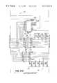
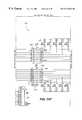
- the parallel port section 300is displayed in FIG. 20, according to the preferred embodiments of the present invention, and includes a parallel connector 330 which connects to ribbon cable 217 for transmission and receipt of a plurality of signals from the remote controller 54 .
- the parallel connector 330includes a BUSY line 332 , a plurality of data lines 334 , an ACK line 336 , a STROBE line 338 , a PAPEROUT line 340 , an AFEED line 344 , an ERR line 346 , an INITIAL line 348 , a SELIN line 350 , a plurality of remote controller return lines 352 , a RCGND line 354 , and a plurality of mounting ground lines 356 .
- the data lines 334are protected by transient voltage suppressors 360 and series resistor network 362 . Signals carried by the data lines 334 are shaped and buffered by inverting Schmitt buffer 335 to yield stable signals on column and row select lines 364 , 366 for use by the matrix communications section 306 .
- the inverting Schmitt buffer 335is enabled by the signal on the EN5V line 368 whenever the drawer is activated.
- the ACK line 336 , the AFEED line 344 , the ERR line 346 , the INITIAL line 348 , the SELIN line 350 , and the BUSY line 332are protected by transient voltage suppressors 370 and series damping resistors (not shown in FIG. 20 ).
- the ACK line 336is an output from the local controller 214 and carries serial signals from the ID slot connector.
- the AFEED line 344is an input to the local controller 214 and carries serial data to an addressable switch 394 , the row and column matrix of connectors 156 , and the ID slot connector.
- the ERR line 346is an output from the local controller 214 and carries a signal from the drawer switch 248 which is representative of the position of the drawer 98 relative to the enclosure 86 .
- the INITIAL line 348is an input to the local controller 214 and carries a signal which is employed, in conjunction with a signal on the SELIN line 350 , to derive data direction signals SDIR 372 and NSDIR 374 .
- the SELIN line 350is an input to the local controller 214 and carries a signal which is employed with the signal on the INITIAL line 348 , as described above, and enables selection of the local controller 214 to output data to the parallel connector 330 , thereby avoiding potential data collisions with data intended for use by the printer 56 .
- the BUSY line 332is an output line and carries serial data from the connectors 154 of the row and column matrix of connectors 156 and the addressable switch 394 .
- the RCGND line 354is an input line and carries a signal which resets the addressable switch 394 whenever the connection is lost between the remote controller 54 and enclosure 86 .
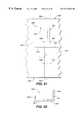
- the receive direction section 302receives signals on the INITIAL line 348 and SELIN line 350 from the parallel port section 300 .
- the SELIN signalis shaped and buffered by the inverting Schmitt buffers 376 , 378 .
- the INITIAL signalis shaped and buffered by the inverting Schmitt buffer 380 and inverted by the inverting Schmitt buffer 382 .
- the AND gates 384 , 386receive the buffered SELIN signal and the inverted and non-inverted INITIAL signals to produce the data direction signals SDIR 372 and NSDIR 374 which are used as data routing signals throughout the local controller 214 .
- the receive/transmit data section 304receives signals on the AFEED line 344 and RCGND line 354 and outputs signals on the BUSY line 332 .
- Signals on the AFEED line 344are shaped and buffered by the inverting Schmitt buffers 388 , 390 to generate signals on MATRIX IN line 392 for use by the matrix communications section 306 .
- An inverted signal on AFEED line 344is NANDed with the signal on NSDIR line 374 to deliver serial data to an addressable switch 394 having a memory which stores a unique identification code (also referred to herein as an address).
- An inverted signal on AFEED line 344is also routed to the DATAIN line 396 for use by the receive/transmit ID slot data section 310 .
- a high signal on the RCGND line 354caused by the loss of the connection between the remote controller 54 and the local controller 214 , is gated by NAND gate 398 to create a low reset signal which resets the addressable switch 394 and, thereby deactivates the drawer 98 .
- the addressable switch 394In response to the receipt of appropriate input data (including a switch address) from AFEED line 344 , via NAND gate 375 , the addressable switch 394 outputs serial data to an inverting Schmitt buffer 400 which provides inverted serial data to a two line-to-one line, open collector multiplexor 402 comprised of NAND gates 404 , 406 .
- Serial output data available from the addressable switch 394upon receipt of appropriate input data, includes a unique identification code for the switch, data residing in the switch's memory, and the status of the switch's bidirectional port.
- the addressable switchis a DS2405 from Dallas Semiconductor Corporation of Dallas, Texas.
- the multiplexor 402selects serial data from either the MATRIX OUT line 408 (i.e., from the matrix communications section 306 ) or the addressable switch 394 and outputs the selected serial data on the BUSY line 332 for receipt by the parallel port section 300 .
- the addressable switch 394has an input/output port 410 which is used to create an enable signal for the drawer 98 on ENABLE line 412 . Upon receipt of an appropriate input signal, the addressable switch 394 sets the input/output port 410 to a low state which activates the drawer 98 to enable functions including communication with the ID slot connector, the drawer switch. 248 , and the matrix communications section 306 (and, hence, the row and column matrix of connectors 156 ).
- the enable section 316receives an enable signal on ENABLE line 412 and outputs a power signal on the EN5V line 368 which is utilized to turn on and off various electronic components of the local controller 214 .
- the enable signalis low, the enable section 316 , using NAND gate 414 and MOSFET transistor 416 , creates a 5-volt signal on the EN5V line 368 , thereby turning on various electronic components.
- the enable section 316creates, preferably, a 0-volt signal on the ENSV line 368 , thereby turning off various electronic components.
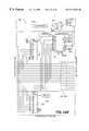
- the matrix communication section 306is displayed in FIG. 24 and has inputs including column and row select lines 364 , 366 , MATRIX IN line 392 , NSDIR line 374 , and the EN5V line 368 .
- the matrix communication section 306communicates bi-directionally with the row and column matrix of connectors 156 via a connector 418 , which is attached to flexible cable 216 , to supply connectors 154 with input data from the MATRIX IN line 392 and to receive output data generated by the electronic devices 194 of the object identification assemblies 182 which are present in the enclosure 86 .
- a demultiplexor 420receives input data from the MATRIX IN line 392 and column select lines 364 .
- the demultiplexor 420Upon being enabled by a power signal received on EN5V line 368 and a low signal on NSDIR line 374 , the demultiplexor 420 decodes the received column selection signal (which identifies the column, of the row and column matrix of connectors 156 , in which the connector 154 to be communicated with resides) to transfer the serial input data on MATRIX IN line 392 to the identified column data line 208 of the row and column matrix of connectors 156 .
- the column data lines 208are pulled up by resistor networks 422 , 424 and reflected signals traveling on column data lines 208 are dampened by resistor networks 426 , 428 .
- the column data lines 208are protected against transient voltages by transient voltage suppressors 430 , 432 .
- a decoder 434receives the row selection signal (which identifies the row, of the row and column matrix of connectors 156 , in which the connector 154 to be communicated with resides) on row select lines 364 and, upon being enabled by a power signal received on EN5V line 368 , the decoder 434 defines a row return line 210 (which is associated with the connector 154 with which communication is desired) by connecting the row return line 210 to an active, low-level logic state, thereby transitioning the row return line 210 from the floating-level logic state in which it normally exists when not selected by the decoder 434 .
- Resistor networks 436 , 438dampen reflected signals traveling on the row return lines 210 and transient voltages are suppressed by transient voltage suppressors 440 , 442 .
- Resistor networks 435 , 437connected to row return lines 210 , prevent oscillation of the signals communicated by the row return lines 210 .
- the matrix communication section 306also comprises cascaded multiplexors 444 , 446 which are connected to column data lines 208 , column select lines 364 , and EN5V line 368 .
- inverter 448inverts the fourth column select line 364 to enable multiplexor 444 to operate when multiplexor 446 does not and vice versa.
- the multiplexors 444 , 446Upon being enabled by a power signal received on EN5V line 368 , the multiplexors 444 , 446 transfer the serial output data from the previously identified column data line 208 (and, hence, from a connector 154 of the row and column matrix of connectors 156 ) to an inverting Schmitt buffer 450 for output on MATRIX OUT line 408 and reception by multiplexor 402 of the receive/transmit data section 304 .
- Decoder 434also provides an output signal on IDENABLE line 452 for receipt by the receive/transmit ID slot data section 310 .
- IDSLOT line 454is connected, via the flexible cable 216 , to the positive data line of the ID slot connector to provide a bi-directional communication path.
- the receive/transmit ID slot data section 310receives a signal on the DATAIN line 396 from the receive/transmit data section 304 and supplies it to IDSLOT line 454 after selection by NAND gates 456 , 458 using a routing signal on the NSDIR line 374 and a routing signal on the IDENABLE line 452 which has been inverted by inverter 460 .
- Serial data from the ID slot connectoris transferred on IDSLOT line 454 to the inverting Schmitt buffer 462 for supply to a two line-to-one line multiplexor 464 comprising NAND gates 466 , 468 .
- NAND gate 466receives input serial data from IDSLOT line 454 and a selection signal on NSDIR line 374 .
- NAND gate 468receives input serial data from IDSLOT line 454 and a selection signal on SDIR line 372 , in addition to a power signal on EN5V line 368 .
- the output signalis provided on ACK line 336 to the parallel port section 300 .
- the transmit enclosure position section 308receives a signal from the drawer switch 248 on POSITION line 224 (also referred to herein as drawer switch signal line 224 ).
- the signalis debounced utilizing an RC circuit 472 and an inverting Schmitt buffer 474 . Transient voltages are suppressed by transient voltage suppressor 476 .
- the inverting Schmitt buffer 474provides an input signal to a multiplexor 478 including NAND gates 480 , 482 .
- NAND gate 480receives input data from the inverting Schmitt buffer 474 , receives a selection signal from NSDIR line 374 , and a power signal from EN5V line 368 .
- NAND gate 482receives input data from the inverting Schmitt buffer 474 and receives a selection signal from SDIR line 372 .
- the output signalis provided on ERR line 346 to the parallel port section 300 .
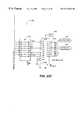
- the lock driver section 312is displayed in FIG. 27 and receives input signals from the inverted fourth line of the column select lines 364 of the matrix communication section 306 , the third line of the column select lines 364 , the NSDIR line 374 , and receives a power signal on EN5V line 368 .
- the input signalsare ANDed by AND gates 484 , 486 to turn on and off MOSFET transistor 488 .
- the MOSFET transistor 488When the MOSFET transistor 488 is turned on, it causes the solenoid actuator 226 to be energized via lock signal lines 222 , thereby unlocking the electrically-actuated lock mechanism 218 .
- the solenoid actuator 226is not energized, thereby enabling the keeper plate 232 to return to its locked position as shown in FIG. 17 .
- the LED driver section 314receives a power signal on EN5V line 368 when the drawer 98 is activated and supplies power to LED's 113 via LED lines 490 , 492 .
- the LED driver section 314includes an oscillator 494 which causes the LED's 113 to flash.
- the power supply section 318receives input power from the fuse holder 82 on the utility panel 62 and conditions and regulates the power to provide a stable source of electrical energy for the local controller 214 and related components.
- the power supply section 318includes decoupling capacitors 496 , 498 to filter out high-speed switching noise created by the logic circuits incorporated in the local controller 214 .
- FIG. 30displays an isolated, front, perspective, schematic view of a storage unit 52 ′ of an inventoriable-object control and tracking system in accordance with a second preferred embodiment of the present invention.
- the storage unit 52 ′is substantially similar to storage units 52 of the first preferred embodiment of the present invention, having an enclosure 86 ′ and a drawer 98 ′ with an assembly retaining structure 116 ′ (referred to in the second preferred embodiment, as a first assembly retaining structure 116 ′) for receipt of object identification assemblies 182 ′ (referred to in the second preferred embodiment, as a first plurality of object identification assemblies 182 ′) and a local controller 214 ′, and additionally includes a second assembly retaining structure 500 for receiving object identification assemblies 502 of a second plurality of object identification assemblies 502 .
- the second assembly retaining structure 500rests atop the top panel 118 ′ of the first assembly retaining structure 116 ′ and comprises a base 504 (i.e., a drip pan for catching any liquid which may drop off of an object identification assembly 502 while the assembly 502 resides in the second assembly retaining structure 500 ) having upwardly extending walls 506 which bound a top surface 508 and define a recess 510 .
- the second assembly retaining structure 500further comprises a housing 512 which extends upward from the top surface 508 of the base 504 and adjacent the back member 106 ′ of the drawer 98 ′ and a channel member 514 which is mounted, within recess 510 , atop the top surface 508 of the base 504 .
- the housing 512has a first panel 516 , an opposed second panel 518 , and a third panel 522 extending between the first and second panels 516 , 518 to partially define a cavity 520 within housing 512 .
- the first panel 516located nearest the front face assembly 104 ′ of the drawer 98 ′, defines a plurality of openings 524 with each opening 524 being defined by an edge 526 (or outer perimeter) which is shaped to receive a portion of an object identification assembly 502 of a second plurality of object identification assemblies 502 (see FIG. 33 ). As illustrated in FIG.
- the first panel 516also defines a longitudinal axis 528 and a lateral axis 530 extending through each opening 524 .
- the edge 526 defining each opening 524is asymmetrical about both axes 528 , 530 , thereby enabling each opening 524 to receive an object identification assembly 502 in only one orientation relative to the opening 524 .
- Such “polarization” of each opening 524is necessary to orient each object identification assembly 502 relative to the housing 512 for proper electrical interaction as described below.
- object identification assemblies 502 of the second plurality of object identification assemblies 502as seen in FIG.
- object identification assemblies 182 ′ of the first plurality of object identification assemblies 182 ′(described above with respect to the first preferred embodiment of the present invention) which are received by slots 120 ′ of top panel 118 ′ of first assembly retaining structure 116 ′.
- the channel member 514 of the second assembly retaining structure 500displayed in FIGS. 30, 32 , and 36 in accordance with the second preferred embodiment of the present invention, has a first leg 532 and a second leg 534 connected by a web 536 which is secured to base 504 of the second assembly retaining structure 500 by fasteners 538 .
- the legs 532 , 534extend between the upwardly rising walls 506 of the base 504 of the second assembly retaining structure 500 with the first leg 532 being positioned nearer the housing 512 and the second leg 534 being positioned nearer the front face assembly 104 ′ of the drawer 98 ′.
- the legs 532 , 534also extend upward from the top surface 508 of base 504 with the first leg 532 extending to a greater elevation than the second leg 534 .
- the first leg 532 and web 536define a plurality of slots 540 , each slot 540 being aligned with a corresponding opening 524 defined by the first panel 516 of housing 512 for receipt of an object identification assembly 502 .
- the portions of the first leg 532 adjacent the slots 540guide the object identification assemblies 502 during insertion and removal of object identification assemblies 502 from the second assembly retaining structure 500 , and provide support for and limit lateral movement of an object identification assembly 502 present in a slot 540 .
- each slot 540preferably, extends through the entire vertical height of the first leg 532 and through the entire thickness of the web 536 and that a corresponding opening 524 , preferably, extends downward to the top surface 508 of base 504 , thereby enabling a received object identification assembly 502 to contact the top surface 508 of base 504 when the assembly 502 is positioned for proper electrical interaction as described below.
- the vertical height of the second leg 532is, preferably, selected to enable an object identification assembly 502 to barely clear the second leg 532 during insertion and removal of object identification assemblies 502 from the second assembly retaining structure 500 .
- an object identification assembly 502comprises an object 542 to be tracked (such as, for example, but not limitation, a license plate), an electronic device 544 having a memory which stores a unique identification code, and an interface member 546 which couples the object 542 and the electronic device 544 .
- the electronic device 544is, like electronic device 194 ′ of the first preferred embodiment, a DS1990A Touch Memory Device available from Dallas Semiconductor Corporation of Dallas, Texas and has a positive data contact 543 and a negative return contact 545 .
- the object 542has a front 548 , a back 550 , side edges 552 , and a top edge 554 .
- the interface member 546see FIGS.
- a crimp ring 561resides about the electronic device 544 , adjacent to the first portion 556 of the interface member 546 , and secures the electronic device 544 to the interface member 546 .
- the second portion 558 of the interface member 546extends adjacent to the back 550 of the object 542 from side edge 552 a in a direction toward side edge 552 b and defines a plurality of slots 562 which receive fasteners 564 , thereby securing the object 542 to the interface member 546 and electrically connecting the return line contact of the electronic device 544 to the interface member 546 and to the object 542 .
- the object identification assembly 502further includes a magnet-holding bracket 566 which is secured to the rear of the second portion 558 of the interface member 546 . In an alternate preferred embodiment of the present invention, the magnet-holding bracket 566 is not present.
- the second assembly retaining structure 500additionally comprises a backplane 568 and plurality of connectors 570 which are substantially similar to the backplane 130 ′ and plurality of connectors 154 ′ of the preferred embodiment of the present invention.
- the backplane 568resides within housing 512 and is secured to the second panel 518 of the housing 512 in a vertical orientation by a plurality of standoffs (not visible).
- Each connector 570 of the plurality of connectors 570is positioned directly behind a corresponding opening 524 of the plurality of openings 524 defined by the first panel 516 of housing 512 .
- the connectors 570define a matrix having, preferably, a single row and multiple columns of connectors 570 .
- Each connector 570comprises a pair of opposed contacts 572 (substantially similar to contacts 158 ′ of connectors 154 ′ of the preferred embodiment of the present invention) which are rigidly mounted to backplane 568 by rivets 574 .
- Each contact 572 ais electrically connected to one of a plurality of column data lines and each contact 572 b is electrically connected to a row return line in a manner substantially similar to the contacts 158 ′ of connectors 154 ′.
- the backplane 568 and its column data lines and row return lineconnect to local controller 214 ′ via a flexible cable (not visible) in order to transfer electrical signals between the backplane 568 and the local controller 214 ′.
- the positive data contact 543engages a contact 572 a and the negative return contact 545 engages a contact 572 b of the particular connector 570 .
- the column data line and row return line connected to the particular connector 570it is possible, as described below, to determine whether or not an electronic device 544 and, hence, an object identification assembly 502 of the second plurality of object identification assemblies 502 is present between the contacts 572 of the particular connector 570 . If an electronic device 544 is present, it is possible, as described below, to read the identification code stored within the electronic device 544 and, hence, the identification code of the object identification assembly 502 via the column data line.
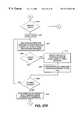
- the processstarts at step 600 and advances to step 602 where the system 50 initializes itself, locates the address of the parallel port 58 of the remote controller 54 which is connected to the storage unit 52 , and determines the speed at which software must execute in order to perform serial communications over parallel communication paths 58 .
- the system 50begins a process of identifying a user who wishes to perform an activity on an object identification assembly 182 , 202 such as, for example, inserting an object identification assembly 182 , 202 into a drawer 98 for receipt by a respective assembly retaining structure 116 , 500 or removing an object identification assembly 182 , 202 from a respective assembly retaining structure 116 , 500 .
- the system 50prompts a user to insert his personal identification assembly into the ID slot 112 of a drawer 98 by displaying prompt text on the video monitor 60 .
- the system 50takes control over all access to the remote controller's parallel port 58 to prevent data collisions created by other application software programs attempting to communicate, via the parallel port 58 , to the printer 56 .
- the system 50reads the ID slots 112 of the various drawers 98 (if more than one drawer 98 is present in the system 50 or the only ID slot 112 if only one drawer 98 is present in the system 50 ) on the drawers' front face 108 to acquire an identification code from the user's personal identification assembly.
- the remote controller 54selects the ID slot 112 by generating appropriate signals on the INITIAL and SELIN lines 348 , 350 , which are communicated through the necessary data communication link(s) 72 , 74 and data communication interfaces 68 , 70 using a serial protocol to the respective local controller 214 , for supply to the positive data contact 204 of the electronic device 194 of the personal identification assembly via AFEED line 344 .
- the electronic device 194outputs its unique identification code through its positive data contact 204 and ACK line 336 for transmission to the remote controller 54 .
- the remote controller 54Upon receiving the identification code contained in the personal identification assembly, the remote controller 54 , at step 610 , verifies that the personal identification assembly is being used by its owner by prompting the user for a password on video monitor 60 , receiving a password from the user at the remote controller 54 , and then determining, at step 612 , whether or not the user is authorized to access the system 50 by looking-up the identification code and password in a table including authorized code/password combinations. If the user is not authorized to access the system 50 , the method loops back to step 604 where the remote controller 54 prompts the user to insert his personal identification assembly. If the user is authorized to access the system 50 , the method continues at step 614 .
- the remote controller 54After determining that the user is authorized, the remote controller 54 , at step 614 , prompts the user on video monitor 60 for the type of activity that the user wishes to perform on an object identification assembly 182 , 502 .
- the types of activitiesinclude for example, but not limitation, inserting (or re-inserting, or returning) an object identification assembly 182 , 502 into a drawer 98 for receipt by a slot 120 (or opening 524 ) and an associated connector 154 , 570 , and removing an object identification assembly 182 , 502 from a slot 120 (or opening 524 ) and an associated connector 154 , 570 of a drawer 98 .
- the remote controller 54receives input from the user, in response to the prompt, which identifies the type of activity that the user wishes to perform. Then, at step 620 , the remote controller 54 evaluates the user's input to determine if the user wishes to remove an object identification assembly 182 , 502 and associated object from a respective assembly retaining structure 116 , 500 .
- tile remote controller 54determines, at step 620 , that the user wishes to remove an object identification assembly 182 , 502 . If the remote controller 54 determines, at step 620 , that the user wishes to remove an object identification assembly 182 , 502 , tile remote controller 54 , according to the preferred method of the present invention, prompts the user on video monitor 60 to provide information related to the removal of an object identification assembly 182 , 502 at step 621 .
- the informationmay include the purpose or reason for the removal of the object identification assembly 182 , 502 , a work order number with which the removal of the object identification assembly 182 , 502 is to be associated with (i.e., when the work order number is utilized in conjunction with the time of removal and time of re-insertion of an object identification assembly 182 , 502 , the remote controller 54 may compute the amount of time required to perform the task identified by the work order number), etc.
- the remote controller 54After receiving the information from the user in response to the prompt and storing the received information on storage media present in a disk drive of the remote controller 54 at step 622 , the remote controller 54 prompts the user on video monitor 60 to identify an object identification assembly 182 , 502 for removal from a drawer 98 at step 623 .
- the remote controller 54receives input from the user at step 624 , in response to the prompt, which identifies the object identification assembly 182 , 502 (and, hence, an object) for removal.
- the remote controller 54determines the location (including the slot 120 or opening 524 , and the drawer 98 , if more than one drawer 98 is present in the system 50 ) of the object identification assembly 182 , 502 identified by the user in step 624 by retrieving the location information from a data file, containing the location information, which is stored, preferably, on the remote controller's hard disk drive.
- the remote controller 54then outputs, at step 628 , the location of the identified object identification assembly 182 , 502 on video monitor 60 by displaying, preferably, a row and column matrix representative of the connectors 154 , 570 of the assembly retaining structure 116 , 500 in which the identified object identification assembly 182 , 502 resides and by indicating, on the display, the particular row and column of the matrix in which the identified object identification assembly 182 , 502 is present.
- the remote controller 54also, preferably, displays an identifier which distinguishes the drawer 98 in which the identified object identification assembly 182 , 502 resides.
- the remote controller 54determines whether or not the system 50 tracks multiple types of objects (for example and not limitation, vehicle keys and vehicle license plates) by reading and evaluating data stored in a configuration file residing on the remote controller's hard disk at step 630 . If the system 50 determines, at step 630 , that it is configured to track only one type of object, the method advances to step 636 , described below.
- objectsfor example and not limitation, vehicle keys and vehicle license plates
- the remote controller 54prompts the user, at step 632 , to prompt the user, on video monitor 60 , to identify the type of object to be inserted into a drawer 98 for receipt by a slot 120 or opening 524 (and respective connectors 154 , 570 ) of a respective assembly retaining structure 116 , 500 .
- the remote controller 54at step 634 , receives input from the user, in response to the prompt at step 632 , which identifies the type of object to be inserted into a drawer 98 .
- the remote controller 54determines, based on the type of object to be received from the user by a drawer 98 , the location (including the slot 120 or opening 524 , and the drawer 98 , if more than one drawer 98 is present in the system 50 ) of a site which is available for receipt of the object identification assembly 182 , 502 by retrieving and comparing location and configuration information from data files stored, preferably, on the remote controller's hard disk drive.
- the location informationincludes the locations of each object identification assembly 182 , 502 which currently resides in an assembly retaining structure 116 , 500 of a drawer 98 and the configuration information includes the locations of the slots 120 , or openings 524 , which are available in a particular drawer 98 when the drawer 98 contains no object identification assemblies 182 , 502 .
- the remote controller 54After determining the location of an available site for receipt of an object identification assembly 182 , 502 , the remote controller 54 then outputs, at step 638 , the location of the available site on video monitor 60 by displaying, preferably, a row and column matrix representative of the connectors 154 , 570 of the assembly retaining structure 116 , 500 in which the available site is present and by indicating, on the display, the particular row and column of the matrix in which the available site is present.
- the remote controller 54also, preferably, displays an identifier which identifies the drawer 98 in which the available site resides. After outputting the location of the available site, the method advances to step 640 as described below.
- the remote controller 54activates the appropriate storage unit 52 , containing the object identification assembly 182 , 502 to be removed or containing an available site for receipt of an object identification assembly 182 , 502 , by establishing communications with the unit's addressable switch 394 through generation of appropriate signals on the INITIAL and SELIN lines 348 , 350 and communicating the unique address of the addressable switch 394 to the addressable switch 394 .
- addressable switch 394replies to the remote controller 54 , acknowledging receipt of its unique address, appropriate signals are sent to the addressable switch 394 over the AFEED line 344 to toggle the status of the switch's bidirectional port to an active state, thereby enabling the supply of electrical power (which was previously not supplied) to the remainder of the local controller 214 .
- the remote controller 54unlocks the appropriate drawer 98 by actuating the drawer's lock mechanism 218 .
- the remote controller 54In order to energize the lock solenoid 226 , the remote controller 54 generates the appropriate signals on the INITIAL and SELIN lines 348 , 350 and supplies an energize signal on data lines 334 .
- the remote controller 54checks to see if the drawer 98 is open by generating the appropriate signals on the INITIAL and SELIN lines 348 , 350 and by reading the signal present on the ERR line 346 . If the signal has a logical low level, the drawer 98 is not open and the method loops back to step 640 to maintain energization of the lock solenoid 226 . If the signal has a logical high level, the drawer 98 is open and the method continues at step 646 where the lock mechanism 218 is reset by removing the energize signal on data lines 334 to de-energize the lock solenoid 226 .
- the system 50monitors, or scans, the object identification assemblies 182 , 502 to detect which, if any, assemblies 182 , 502 are present in the drawer 98 . Detection of the assemblies 182 , 502 is accomplished by the remote controller 54 selecting each connector 154 , 570 of a row and column matrix of connectors 154 , 570 (by transmitting the row and column addresses of the connector 154 , 570 to the local controller 214 ) and attempting to read output data from the data output contact of an electronic device 194 (by supplying appropriate data signals to the data output contact and waiting for a response from the electronic device 194 ) which may or may not be present in the selected connector 154 , 570 .
- output dataincluding the unique identification code of the electronic device 194 , is communicated by the local controller 214 to the remote controller 54 on BUSY line 332 .
- the remote controller 54stores the identification code and location of the object identification assembly 182 , 502 in a list for subsequent review.
- the remote controller 54detects, at step 650 , whether or not any object identification assemblies 182 , 502 have been inserted or removed from the drawer 98 by comparing the identification codes of the assemblies 182 , 502 which discovered and stored in a list at step 648 with the identification codes of the assemblies 182 , 502 which were discovered and stored in a different list on the remote controller's hard disk drive at a previous point in time. If no object identification assembly 182 , 502 removals or insertions are detected at step 650 , the method advances to step 652 , as discussed below, where the remote controller 54 checks to see whether or not the drawer 98 is closed.
- the remote controller 54If object identification assembly 182 , 502 removals or insertions are detected at step 650 , the remote controller 54 outputs the identification codes of the assemblies 182 , 502 which were removed or inserted on the video monitor 60 at step 654 .
- the removed or inserted object identification assemblies 182 , 502are then stored, at step 656 , in a log file by the remote controller 54 to replace the previous list of assemblies 182 , 502 which are present in an assembly retaining structure 116 , 540 of the drawer 98 .
- the stored informationincludes the user's identification code, the object identification code, and the date and time of the activity.
- the remote controller 54checks to see if the drawer 98 is closed by generating the appropriate signals on the INITIAL and SELIN lines 348 , 350 and reading the signal present on the ERR line 346 . If the signal has a logical low level, the drawer 98 is determined to be closed and the method advances to step 658 . If the signal has a logical high level, the drawer 98 is determined to be open and the method loops back to step 648 to scan the object identification assemblies 182 , 502 present in the drawer 98 .
- the remote controller 54reads the identification codes of the object identification assemblies 182 which are present in the drawer 98 .
- the remote controller 54scans the connectors 154 , 570 by selecting each connector 154 , 570 of each row and column matrix of connectors 154 , 570 and attempting to read output data, on BUSY line 332 , from an electronic device 194 which may or may not be present in the selected connector 154 , 570 .
- the remote controller 54processes the identification codes held by the connectors 154 , 570 and received from the object identification assemblies 182 , 502 at step 658 , as described above, to determine and log which assemblies 182 , 502 were removed and/or inserted, which user did so, and the date and time when the removal or insertion was made by the user.
- the remote controller 54also determines, by comparing the identification codes of the assemblies 182 , 502 presently in the drawer 98 with those already removed from the drawer 98 and with an acceptable amount of time stored in a configuration file on the remote controller 54 , which assemblies 182 , 502 have been absent from the drawer 98 for an excessive amount of time and displays them on the video monitor 60 .
- the remote controller 54performs supplementary data processing related to, and in conjunction with, the information collected from the user at step 622 .
- the amount of time required to do a jobmay be computed from the time of removal and re-insertion of an object identification assembly 182 , 502 (i.e., connected to a door key) and associated with a work order number
- the amount of time spent on vehicle test drivesmay be computed from the times of removals and re-insertions of object identification assemblies 182 , 502 (i.e., connected to vehicle keys) and associated with the salesperson who accessed the assemblies 182 , 502 , etc.
- control over the remote controller's parallel port 58is released and the method loops back to step 604 where the user is prompted to insert his personal identification assembly.
- the identification codes of the object identification assemblies 182 , 502are loaded into the remote controller 54 for later use by receiving the assemblies 182 , 502 in the front face ID slot 112 of a drawer 98 and then by reading their identification codes. After reading, the identification codes are associated with descriptive information related to the object being controlled and tracked by the system 50 .
Landscapes
- Physics & Mathematics (AREA)
- General Physics & Mathematics (AREA)
- Business, Economics & Management (AREA)
- Accounting & Taxation (AREA)
- Lock And Its Accessories (AREA)
Abstract
Description
Claims (16)
Priority Applications (3)
| Application Number | Priority Date | Filing Date | Title |
|---|---|---|---|
| US09/389,820US6317044B1 (en) | 1996-09-05 | 1999-09-03 | Inventoriable object control and tracking system |
| US10/035,530US6707380B2 (en) | 1995-09-08 | 2001-10-23 | Inventoriable-object control and tracking system |
| US10/766,427US7342494B2 (en) | 1995-09-08 | 2004-01-27 | Inventoriable-object control and tracking system |
Applications Claiming Priority (3)
| Application Number | Priority Date | Filing Date | Title |
|---|---|---|---|
| US08/708,617US5801628A (en) | 1995-09-08 | 1996-09-05 | Inventoriable-object control and tracking system |
| US09/073,757US6075441A (en) | 1996-09-05 | 1998-05-06 | Inventoriable-object control and tracking system |
| US09/389,820US6317044B1 (en) | 1996-09-05 | 1999-09-03 | Inventoriable object control and tracking system |
Related Parent Applications (1)
| Application Number | Title | Priority Date | Filing Date |
|---|---|---|---|
| US09/073,757ContinuationUS6075441A (en) | 1995-09-08 | 1998-05-06 | Inventoriable-object control and tracking system |
Related Child Applications (2)
| Application Number | Title | Priority Date | Filing Date |
|---|---|---|---|
| US29/121,141DivisionUSD444331S1 (en) | 1996-09-05 | 2000-03-31 | Drawer panel |
| US10/035,530ContinuationUS6707380B2 (en) | 1995-09-08 | 2001-10-23 | Inventoriable-object control and tracking system |
Publications (1)
| Publication Number | Publication Date |
|---|---|
| US6317044B1true US6317044B1 (en) | 2001-11-13 |
Family
ID=24846518
Family Applications (4)
| Application Number | Title | Priority Date | Filing Date |
|---|---|---|---|
| US09/073,757Expired - LifetimeUS6075441A (en) | 1995-09-08 | 1998-05-06 | Inventoriable-object control and tracking system |
| US09/389,820Expired - LifetimeUS6317044B1 (en) | 1995-09-08 | 1999-09-03 | Inventoriable object control and tracking system |
| US10/035,530Expired - LifetimeUS6707380B2 (en) | 1995-09-08 | 2001-10-23 | Inventoriable-object control and tracking system |
| US10/766,427Expired - Fee RelatedUS7342494B2 (en) | 1995-09-08 | 2004-01-27 | Inventoriable-object control and tracking system |
Family Applications Before (1)
| Application Number | Title | Priority Date | Filing Date |
|---|---|---|---|
| US09/073,757Expired - LifetimeUS6075441A (en) | 1995-09-08 | 1998-05-06 | Inventoriable-object control and tracking system |
Family Applications After (2)
| Application Number | Title | Priority Date | Filing Date |
|---|---|---|---|
| US10/035,530Expired - LifetimeUS6707380B2 (en) | 1995-09-08 | 2001-10-23 | Inventoriable-object control and tracking system |
| US10/766,427Expired - Fee RelatedUS7342494B2 (en) | 1995-09-08 | 2004-01-27 | Inventoriable-object control and tracking system |
Country Status (1)
| Country | Link |
|---|---|
| US (4) | US6075441A (en) |
Cited By (25)
| Publication number | Priority date | Publication date | Assignee | Title |
|---|---|---|---|---|
| US6650240B2 (en)* | 2002-01-18 | 2003-11-18 | Techtalion Limited | Apparatus and method for tracking articles during travel |
| US6707380B2 (en) | 1995-09-08 | 2004-03-16 | Key-Trak, Inc. | Inventoriable-object control and tracking system |
| US6731211B1 (en)* | 2002-11-20 | 2004-05-04 | Micheal A. King | Key control tag |
| US20040090424A1 (en)* | 2002-11-05 | 2004-05-13 | Hurley Gerald C. | Integrated information presentation system with enviromental controls |
| US6737961B2 (en)* | 2002-08-14 | 2004-05-18 | Omega Patents, L.L.C. | Secure, vehicle key, storage device and associated method |
| US20040111323A1 (en)* | 2002-12-05 | 2004-06-10 | Niederland Roger A | Object controlled access and inventory system |
| US20040150508A1 (en)* | 2003-01-31 | 2004-08-05 | General Electric Company | System for managing physical assets |
| US20040153386A1 (en)* | 2002-08-19 | 2004-08-05 | George Eckerdt | Tangible security asset management system and methods thereof |
| US6801245B2 (en) | 2002-01-18 | 2004-10-05 | Imageid Ltd. | Method for automatic identification and data capture |
| US6867695B2 (en) | 2001-02-01 | 2005-03-15 | Key Register Systems, Inc. | Object storage and tracking system, an object tracking unit and a container for object tracking units |
| US6900741B1 (en)* | 1999-09-15 | 2005-05-31 | Waerneloev Johnny | Method and an apparatus for identification and control of handling of keys and the like |
| US7042334B2 (en) | 2003-01-31 | 2006-05-09 | General Electric Company | Methods for managing access to physical assets |
| US7061367B2 (en) | 2002-04-30 | 2006-06-13 | General Electric Company | Managing access to physical assets |
| US20060288101A1 (en)* | 2003-08-19 | 2006-12-21 | Key Systems, Inc. | Multipurpose Interface and Control System |
| US20080088447A1 (en)* | 2006-10-13 | 2008-04-17 | Flores Eduardo Ruiz Esparza | Item tracking system |
| US20100252626A1 (en)* | 2009-04-01 | 2010-10-07 | Rfid Mexico S.A. De C.V. | Portable container inventory control system |
| US7965190B2 (en) | 2001-08-09 | 2011-06-21 | Key Control Holding, Inc. | Object tracking system with automated system control and user identification |
| US20110301749A1 (en)* | 2010-06-04 | 2011-12-08 | Pepsico, Inc. | Networked vendor for workplace or controlled environment |
| US8107114B2 (en)* | 1999-05-25 | 2012-01-31 | Silverbrook Research Pty Ltd | Facsimile delivery through interaction with printed document |
| US8194045B1 (en) | 2005-01-27 | 2012-06-05 | Singleton Technology, Llc | Transaction automation and archival system using electronic contract disclosure units |
| US8228299B1 (en) | 2005-01-27 | 2012-07-24 | Singleton Technology, Llc | Transaction automation and archival system using electronic contract and disclosure units |
| US20120268236A1 (en)* | 2011-04-20 | 2012-10-25 | Key Systems, Inc. | Security System for Containers |
| US8610574B2 (en) | 2009-06-15 | 2013-12-17 | Gerald Isaac Kestenbaum | Item storage and tracking system |
| US9493030B2 (en)* | 2015-01-19 | 2016-11-15 | Isamar Valencia | Pen support rack having biometric access restriction |
| US9670694B2 (en) | 2007-04-12 | 2017-06-06 | Utc Fire & Security Americas Corporation, Inc. | Restricted range lockbox, access device and methods |
Families Citing this family (454)
| Publication number | Priority date | Publication date | Assignee | Title |
|---|---|---|---|---|
| USD444331S1 (en) | 1996-09-05 | 2001-07-03 | Key-Trak, Inc. | Drawer panel |
| EP1770592B1 (en) | 1998-08-14 | 2009-10-07 | 3M Innovative Properties Company | Method of interrogating a package bearing an RFID tag |
| CA2343412A1 (en) | 1998-09-11 | 2000-03-23 | William C. Maloney | Object control and tracking system with zonal transition detection |
| US6262664B1 (en) | 1998-09-11 | 2001-07-17 | Key-Trak, Inc. | Tamper detection prevention for an object control and tracking system |
| AU6032699A (en)* | 1998-09-11 | 2000-04-03 | Key-Trak, Inc. | Mobile object tracking system |
| AU5916899A (en)* | 1998-09-11 | 2000-04-03 | Key-Trak, Inc. | Objet carriers for an object control and tracking system |
| US6891473B2 (en)* | 1998-09-11 | 2005-05-10 | Key-Trak, Inc. | Object carriers and lighted tags for an object control and tracking system |
| EP1112558A4 (en) | 1998-09-11 | 2002-07-31 | Key Trak Inc | Object tracking system with non-contact object detection and identification |
| US6418416B1 (en) | 1999-04-02 | 2002-07-09 | Supplypro, Inc. | Inventory management system and method |
| US6348864B1 (en)* | 2000-05-06 | 2002-02-19 | Magnex Corporation | Organizer management system using R.F. identification |
| USRE47599E1 (en) | 2000-10-20 | 2019-09-10 | Promega Corporation | RF point of sale and delivery method and system using communication with remote computer and having features to read a large number of RF tags |
| WO2002035432A1 (en) | 2000-10-20 | 2002-05-02 | Promega Corporation | Radio frequency identification method and system of distributing products |
| US20020183882A1 (en) | 2000-10-20 | 2002-12-05 | Michael Dearing | RF point of sale and delivery method and system using communication with remote computer and having features to read a large number of RF tags |
| US20020105425A1 (en)* | 2000-10-23 | 2002-08-08 | Supplypro, Inc. | Walk-in crib |
| US6600418B2 (en) | 2000-12-12 | 2003-07-29 | 3M Innovative Properties Company | Object tracking and management system and method using radio-frequency identification tags |
| US20040069851A1 (en)* | 2001-03-13 | 2004-04-15 | Grunes Mitchell B. | Radio frequency identification reader with removable media |
| US6812838B1 (en) | 2001-04-26 | 2004-11-02 | Key-Trak, Inc. | Key control system using separate ID and location detection mechanisms |
| US20020180588A1 (en)* | 2001-06-05 | 2002-12-05 | Erickson David P. | Radio frequency identification in document management |
| US20050032151A1 (en)* | 2001-06-05 | 2005-02-10 | Eisenberg Peter M. | Methods of managing the transfer and use of data |
| US7588185B2 (en) | 2001-06-07 | 2009-09-15 | 3M Innovative Properties Company | RFID data collection and use |
| US6707381B1 (en)* | 2001-06-26 | 2004-03-16 | Key-Trak, Inc. | Object tracking method and system with object identification and verification |
| US20030069815A1 (en)* | 2001-10-10 | 2003-04-10 | 3M Innovative Properties Company | RFID time tracking |
| US6669089B2 (en) | 2001-11-12 | 2003-12-30 | 3M Innovative Properties Co | Radio frequency identification systems for asset tracking |
| US20030117281A1 (en)* | 2001-12-21 | 2003-06-26 | Timur Sriharto | Dynamic control containment unit |
| US6883125B2 (en)* | 2002-01-24 | 2005-04-19 | International Business Machines Corporation | Logging insertion/removal of server blades in a data processing system |
| US7458061B2 (en)* | 2002-06-14 | 2008-11-25 | Sun Microsystems, Inc. | Protecting object identity in a language with built-in synchronization objects |
| US20040229560A1 (en)* | 2002-10-10 | 2004-11-18 | Maloney William C. | Methods of tracking and verifying human assets |
| US9060770B2 (en) | 2003-05-20 | 2015-06-23 | Ethicon Endo-Surgery, Inc. | Robotically-driven surgical instrument with E-beam driver |
| US20070084897A1 (en) | 2003-05-20 | 2007-04-19 | Shelton Frederick E Iv | Articulating surgical stapling instrument incorporating a two-piece e-beam firing mechanism |
| US6880754B1 (en) | 2003-05-30 | 2005-04-19 | Handytrack Key Control Systems, Llc | Object container and location tracking system with randomized internal object storage location |
| US6882282B1 (en) | 2003-08-07 | 2005-04-19 | Handytrack Key Control Systems, Llc | Object storage and location tracking system with remotely stored and accessible data |
| US7584869B2 (en)* | 2004-04-15 | 2009-09-08 | Redbox Automated Retail, Llc | Article dispensing system and method for same |
| US20060259191A1 (en)* | 2005-04-22 | 2006-11-16 | Lowe J M | System and method for vending vendible media products |
| US7447605B2 (en) | 2004-04-15 | 2008-11-04 | Redbox Automated Retail, Llc | System and method for calibrating a vending apparatus |
| US9072535B2 (en) | 2011-05-27 | 2015-07-07 | Ethicon Endo-Surgery, Inc. | Surgical stapling instruments with rotatable staple deployment arrangements |
| US11890012B2 (en) | 2004-07-28 | 2024-02-06 | Cilag Gmbh International | Staple cartridge comprising cartridge body and attached support |
| US11998198B2 (en) | 2004-07-28 | 2024-06-04 | Cilag Gmbh International | Surgical stapling instrument incorporating a two-piece E-beam firing mechanism |
| US8215531B2 (en) | 2004-07-28 | 2012-07-10 | Ethicon Endo-Surgery, Inc. | Surgical stapling instrument having a medical substance dispenser |
| US20060113302A1 (en)* | 2004-09-09 | 2006-06-01 | Inteligistics, Inc. | Modular shipping unit and system |
| US7243476B2 (en)* | 2004-12-03 | 2007-07-17 | Checkpoint Systems, Inc. | Method and system for tracking items in a shipping facility |
| US7295120B2 (en)* | 2004-12-10 | 2007-11-13 | 3M Innovative Properties Company | Device for verifying a location of a radio-frequency identification (RFID) tag on an item |
| US7221274B2 (en)* | 2004-12-30 | 2007-05-22 | Alpha Security Products, Inc. | Docking station for security key |
| US7978060B2 (en)* | 2005-02-14 | 2011-07-12 | Inteligistics, Inc. | Identification system |
| US7382248B2 (en)* | 2005-02-18 | 2008-06-03 | Retriever Industries Llc | Tracking system |
| DE102005014343C5 (en)* | 2005-03-24 | 2012-11-08 | ASTRA Gesellschaft für Asset Management mbH & Co. KG | stocker |
| US8060247B2 (en)* | 2005-04-22 | 2011-11-15 | Redbox Automated Retail, Llc | System and method for communicating secondary vending options |
| US20060289650A1 (en)* | 2005-06-27 | 2006-12-28 | Mobile Aspects, Inc. | Networked monitoring system |
| US11484312B2 (en) | 2005-08-31 | 2022-11-01 | Cilag Gmbh International | Staple cartridge comprising a staple driver arrangement |
| US11246590B2 (en) | 2005-08-31 | 2022-02-15 | Cilag Gmbh International | Staple cartridge including staple drivers having different unfired heights |
| US7669746B2 (en) | 2005-08-31 | 2010-03-02 | Ethicon Endo-Surgery, Inc. | Staple cartridges for forming staples having differing formed staple heights |
| US7648065B2 (en)* | 2005-08-31 | 2010-01-19 | The Stanley Works | Storage cabinet with improved RFID antenna system |
| US9237891B2 (en) | 2005-08-31 | 2016-01-19 | Ethicon Endo-Surgery, Inc. | Robotically-controlled surgical stapling devices that produce formed staples having different lengths |
| US7934630B2 (en) | 2005-08-31 | 2011-05-03 | Ethicon Endo-Surgery, Inc. | Staple cartridges for forming staples having differing formed staple heights |
| US10159482B2 (en) | 2005-08-31 | 2018-12-25 | Ethicon Llc | Fastener cartridge assembly comprising a fixed anvil and different staple heights |
| US20070106317A1 (en) | 2005-11-09 | 2007-05-10 | Shelton Frederick E Iv | Hydraulically and electrically actuated articulation joints for surgical instruments |
| US7987020B1 (en)* | 2006-01-27 | 2011-07-26 | Swinea Jr Jessie Donald | Key storage and dispensing assembly and a method for storing and dispensing keys |
| US11793518B2 (en) | 2006-01-31 | 2023-10-24 | Cilag Gmbh International | Powered surgical instruments with firing system lockout arrangements |
| US20110295295A1 (en) | 2006-01-31 | 2011-12-01 | Ethicon Endo-Surgery, Inc. | Robotically-controlled surgical instrument having recording capabilities |
| US11278279B2 (en) | 2006-01-31 | 2022-03-22 | Cilag Gmbh International | Surgical instrument assembly |
| US20120292367A1 (en) | 2006-01-31 | 2012-11-22 | Ethicon Endo-Surgery, Inc. | Robotically-controlled end effector |
| US8186555B2 (en) | 2006-01-31 | 2012-05-29 | Ethicon Endo-Surgery, Inc. | Motor-driven surgical cutting and fastening instrument with mechanical closure system |
| US11224427B2 (en)* | 2006-01-31 | 2022-01-18 | Cilag Gmbh International | Surgical stapling system including a console and retraction assembly |
| US8820603B2 (en)* | 2006-01-31 | 2014-09-02 | Ethicon Endo-Surgery, Inc. | Accessing data stored in a memory of a surgical instrument |
| US7845537B2 (en) | 2006-01-31 | 2010-12-07 | Ethicon Endo-Surgery, Inc. | Surgical instrument having recording capabilities |
| US20110024477A1 (en) | 2009-02-06 | 2011-02-03 | Hall Steven G | Driven Surgical Stapler Improvements |
| US8708213B2 (en) | 2006-01-31 | 2014-04-29 | Ethicon Endo-Surgery, Inc. | Surgical instrument having a feedback system |
| US7753904B2 (en) | 2006-01-31 | 2010-07-13 | Ethicon Endo-Surgery, Inc. | Endoscopic surgical instrument with a handle that can articulate with respect to the shaft |
| US8992422B2 (en) | 2006-03-23 | 2015-03-31 | Ethicon Endo-Surgery, Inc. | Robotically-controlled endoscopic accessory channel |
| US8322455B2 (en) | 2006-06-27 | 2012-12-04 | Ethicon Endo-Surgery, Inc. | Manually driven surgical cutting and fastening instrument |
| US10568652B2 (en) | 2006-09-29 | 2020-02-25 | Ethicon Llc | Surgical staples having attached drivers of different heights and stapling instruments for deploying the same |
| US11980366B2 (en) | 2006-10-03 | 2024-05-14 | Cilag Gmbh International | Surgical instrument |
| US8684253B2 (en) | 2007-01-10 | 2014-04-01 | Ethicon Endo-Surgery, Inc. | Surgical instrument with wireless communication between a control unit of a robotic system and remote sensor |
| US11291441B2 (en) | 2007-01-10 | 2022-04-05 | Cilag Gmbh International | Surgical instrument with wireless communication between control unit and remote sensor |
| US8632535B2 (en) | 2007-01-10 | 2014-01-21 | Ethicon Endo-Surgery, Inc. | Interlock and surgical instrument including same |
| US20080169333A1 (en) | 2007-01-11 | 2008-07-17 | Shelton Frederick E | Surgical stapler end effector with tapered distal end |
| US11039836B2 (en) | 2007-01-11 | 2021-06-22 | Cilag Gmbh International | Staple cartridge for use with a surgical stapling instrument |
| US7673782B2 (en) | 2007-03-15 | 2010-03-09 | Ethicon Endo-Surgery, Inc. | Surgical stapling instrument having a releasable buttress material |
| US7710275B2 (en) | 2007-03-16 | 2010-05-04 | Promega Corporation | RFID reader enclosure and man-o-war RFID reader system |
| US8931682B2 (en) | 2007-06-04 | 2015-01-13 | Ethicon Endo-Surgery, Inc. | Robotically-controlled shaft based rotary drive systems for surgical instruments |
| US11564682B2 (en) | 2007-06-04 | 2023-01-31 | Cilag Gmbh International | Surgical stapler device |
| US7753245B2 (en) | 2007-06-22 | 2010-07-13 | Ethicon Endo-Surgery, Inc. | Surgical stapling instruments |
| US11849941B2 (en) | 2007-06-29 | 2023-12-26 | Cilag Gmbh International | Staple cartridge having staple cavities extending at a transverse angle relative to a longitudinal cartridge axis |
| US7748607B2 (en)* | 2007-08-23 | 2010-07-06 | Target Brands, Inc. | Transaction product with removable articles |
| US20090089187A1 (en)* | 2007-09-28 | 2009-04-02 | Redbox Automated Retail, Llc | Article Vending Machine And Method for Auditing Inventory While Article Vending Machine Remains Operational |
| US8768789B2 (en) | 2012-03-07 | 2014-07-01 | Redbox Automated Retail, Llc | System and method for optimizing utilization of inventory space for dispensable articles |
| US8712872B2 (en) | 2012-03-07 | 2014-04-29 | Redbox Automated Retail, Llc | System and method for optimizing utilization of inventory space for dispensable articles |
| US9886809B2 (en) | 2007-09-28 | 2018-02-06 | Redbox Automated Retail, Llc | Article dispensing machine and method for auditing inventory while article dispensing machine remains operational |
| US20090167502A1 (en)* | 2007-12-31 | 2009-07-02 | 3M Innovative Properties Company | Device for verifying a location and functionality of a radio-frequency identification (RFID) tag on an item |
| US8573465B2 (en) | 2008-02-14 | 2013-11-05 | Ethicon Endo-Surgery, Inc. | Robotically-controlled surgical end effector system with rotary actuated closure systems |
| US8636736B2 (en) | 2008-02-14 | 2014-01-28 | Ethicon Endo-Surgery, Inc. | Motorized surgical cutting and fastening instrument |
| JP5410110B2 (en) | 2008-02-14 | 2014-02-05 | エシコン・エンド−サージェリィ・インコーポレイテッド | Surgical cutting / fixing instrument with RF electrode |
| US9179912B2 (en) | 2008-02-14 | 2015-11-10 | Ethicon Endo-Surgery, Inc. | Robotically-controlled motorized surgical cutting and fastening instrument |
| US7819298B2 (en) | 2008-02-14 | 2010-10-26 | Ethicon Endo-Surgery, Inc. | Surgical stapling apparatus with control features operable with one hand |
| US11986183B2 (en) | 2008-02-14 | 2024-05-21 | Cilag Gmbh International | Surgical cutting and fastening instrument comprising a plurality of sensors to measure an electrical parameter |
| US7866527B2 (en) | 2008-02-14 | 2011-01-11 | Ethicon Endo-Surgery, Inc. | Surgical stapling apparatus with interlockable firing system |
| US9585657B2 (en) | 2008-02-15 | 2017-03-07 | Ethicon Endo-Surgery, Llc | Actuator for releasing a layer of material from a surgical end effector |
| US20090207022A1 (en)* | 2008-02-19 | 2009-08-20 | M/A-Com, Inc. | RFID Asset Tracking Method and Apparatus |
| US20090224875A1 (en)* | 2008-03-06 | 2009-09-10 | Vira Manufacturing, Inc. | System for preventing theft of articles from an enclosure |
| US8502667B2 (en)* | 2008-06-09 | 2013-08-06 | Rangaswamy Narayanan | Activity based management system |
| US7710830B2 (en)* | 2008-09-02 | 2010-05-04 | Accuwalk Llc | Outing record device |
| US9005230B2 (en) | 2008-09-23 | 2015-04-14 | Ethicon Endo-Surgery, Inc. | Motorized surgical instrument |
| US11648005B2 (en) | 2008-09-23 | 2023-05-16 | Cilag Gmbh International | Robotically-controlled motorized surgical instrument with an end effector |
| US8210411B2 (en) | 2008-09-23 | 2012-07-03 | Ethicon Endo-Surgery, Inc. | Motor-driven surgical cutting instrument |
| US9386983B2 (en) | 2008-09-23 | 2016-07-12 | Ethicon Endo-Surgery, Llc | Robotically-controlled motorized surgical instrument |
| US8608045B2 (en) | 2008-10-10 | 2013-12-17 | Ethicon Endo-Sugery, Inc. | Powered surgical cutting and stapling apparatus with manually retractable firing system |
| US8414471B2 (en)* | 2008-10-28 | 2013-04-09 | Mobile Aspects, Inc. | Endoscope storage cabinet, tracking system, and signal emitting member |
| US8191781B2 (en)* | 2008-12-23 | 2012-06-05 | Ncr Corporation | Method and apparatus for automated access control system |
| US8517239B2 (en) | 2009-02-05 | 2013-08-27 | Ethicon Endo-Surgery, Inc. | Surgical stapling instrument comprising a magnetic element driver |
| RU2525225C2 (en) | 2009-02-06 | 2014-08-10 | Этикон Эндо-Серджери, Инк. | Improvement of drive surgical suturing instrument |
| US8450997B2 (en)* | 2009-04-28 | 2013-05-28 | Brown University | Electromagnetic position and orientation sensing system |
| TW201104451A (en)* | 2009-07-29 | 2011-02-01 | Inventec Corp | Method for detecting a node of a server device |
| US20110047010A1 (en)* | 2009-08-21 | 2011-02-24 | Redbox Automated Retail, Llc | Article vending machine and method for receiving restricted discount codes |
| US8996162B2 (en)* | 2009-09-05 | 2015-03-31 | Redbox Automated Retail, Llc | Article vending machine and method for exchanging an inoperable article for an operable article |
| US9104990B2 (en) | 2009-09-05 | 2015-08-11 | Redbox Automated Retail, Llc | Article vending machine and method for exchanging an inoperable article for an operable article |
| US8851354B2 (en) | 2009-12-24 | 2014-10-07 | Ethicon Endo-Surgery, Inc. | Surgical cutting instrument that analyzes tissue thickness |
| US8220688B2 (en) | 2009-12-24 | 2012-07-17 | Ethicon Endo-Surgery, Inc. | Motor-driven surgical cutting instrument with electric actuator directional control assembly |
| US8648699B2 (en) | 2010-07-19 | 2014-02-11 | Mobile Aspects, Inc. | Item tracking system and arrangement |
| US8783543B2 (en) | 2010-07-30 | 2014-07-22 | Ethicon Endo-Surgery, Inc. | Tissue acquisition arrangements and methods for surgical stapling devices |
| US9569911B2 (en) | 2010-08-23 | 2017-02-14 | Redbox Automated Retail, Llc | Secondary media return system and method |
| US8538581B2 (en) | 2010-09-03 | 2013-09-17 | Redbox Automated Retail, Llc | Article vending machine and method for authenticating received articles |
| CN102411411A (en)* | 2010-09-23 | 2012-04-11 | 鸿富锦精密工业(深圳)有限公司 | Computer shell |
| US12213666B2 (en) | 2010-09-30 | 2025-02-04 | Cilag Gmbh International | Tissue thickness compensator comprising layers |
| US9629814B2 (en) | 2010-09-30 | 2017-04-25 | Ethicon Endo-Surgery, Llc | Tissue thickness compensator configured to redistribute compressive forces |
| US10945731B2 (en) | 2010-09-30 | 2021-03-16 | Ethicon Llc | Tissue thickness compensator comprising controlled release and expansion |
| US11925354B2 (en) | 2010-09-30 | 2024-03-12 | Cilag Gmbh International | Staple cartridge comprising staples positioned within a compressible portion thereof |
| US11812965B2 (en) | 2010-09-30 | 2023-11-14 | Cilag Gmbh International | Layer of material for a surgical end effector |
| US9016542B2 (en) | 2010-09-30 | 2015-04-28 | Ethicon Endo-Surgery, Inc. | Staple cartridge comprising compressible distortion resistant components |
| US9386988B2 (en) | 2010-09-30 | 2016-07-12 | Ethicon End-Surgery, LLC | Retainer assembly including a tissue thickness compensator |
| US11298125B2 (en) | 2010-09-30 | 2022-04-12 | Cilag Gmbh International | Tissue stapler having a thickness compensator |
| US9351730B2 (en) | 2011-04-29 | 2016-05-31 | Ethicon Endo-Surgery, Llc | Tissue thickness compensator comprising channels |
| US9788834B2 (en) | 2010-09-30 | 2017-10-17 | Ethicon Llc | Layer comprising deployable attachment members |
| US8695866B2 (en) | 2010-10-01 | 2014-04-15 | Ethicon Endo-Surgery, Inc. | Surgical instrument having a power control circuit |
| US9336665B2 (en) | 2011-02-10 | 2016-05-10 | Wg Security Products | EAS tag with arming switch |
| AU2012250197B2 (en) | 2011-04-29 | 2017-08-10 | Ethicon Endo-Surgery, Inc. | Staple cartridge comprising staples positioned within a compressible portion thereof |
| NL2006737C2 (en)* | 2011-05-06 | 2012-11-08 | Capturetags B V | MANAGEMENT SYSTEM FOR OBJECTS FOR example KEYS. |
| US11207064B2 (en) | 2011-05-27 | 2021-12-28 | Cilag Gmbh International | Automated end effector component reloading system for use with a robotic system |
| US8919656B2 (en) | 2011-06-02 | 2014-12-30 | Key Systems, Inc. | Memory button mount |
| CA2838944A1 (en) | 2011-06-14 | 2012-12-20 | Redbox Automated Retail, Llc | System and method for substituting a media article with alternative media |
| EP2734972A4 (en) | 2011-07-20 | 2014-12-03 | Redbox Automated Retail Llc | System and method for providing the identification of geographically closest article dispensing machines |
| CA2843589A1 (en) | 2011-08-02 | 2013-02-07 | Redbox Automated Retail, Llc | System and method for generating notifications related to new media |
| US9286617B2 (en) | 2011-08-12 | 2016-03-15 | Redbox Automated Retail, Llc | System and method for applying parental control limits from content providers to media content |
| US10169822B2 (en) | 2011-12-02 | 2019-01-01 | Spireon, Inc. | Insurance rate optimization through driver behavior monitoring |
| US8510200B2 (en) | 2011-12-02 | 2013-08-13 | Spireon, Inc. | Geospatial data based assessment of driver behavior |
| USD677447S1 (en) | 2012-02-09 | 2013-03-12 | Susanne L. Shoemaker | Panty garment |
| JP6224070B2 (en) | 2012-03-28 | 2017-11-01 | エシコン・エンド−サージェリィ・インコーポレイテッドEthicon Endo−Surgery,Inc. | Retainer assembly including tissue thickness compensator |
| BR112014024098B1 (en) | 2012-03-28 | 2021-05-25 | Ethicon Endo-Surgery, Inc. | staple cartridge |
| MX358135B (en) | 2012-03-28 | 2018-08-06 | Ethicon Endo Surgery Inc | Tissue thickness compensator comprising a plurality of layers. |
| US9747253B2 (en) | 2012-06-05 | 2017-08-29 | Redbox Automated Retail, Llc | System and method for simultaneous article retrieval and transaction validation |
| US9101358B2 (en) | 2012-06-15 | 2015-08-11 | Ethicon Endo-Surgery, Inc. | Articulatable surgical instrument comprising a firing drive |
| US20140001231A1 (en) | 2012-06-28 | 2014-01-02 | Ethicon Endo-Surgery, Inc. | Firing system lockout arrangements for surgical instruments |
| US12383267B2 (en) | 2012-06-28 | 2025-08-12 | Cilag Gmbh International | Robotically powered surgical device with manually-actuatable reversing system |
| US9408606B2 (en) | 2012-06-28 | 2016-08-09 | Ethicon Endo-Surgery, Llc | Robotically powered surgical device with manually-actuatable reversing system |
| US9289256B2 (en) | 2012-06-28 | 2016-03-22 | Ethicon Endo-Surgery, Llc | Surgical end effectors having angled tissue-contacting surfaces |
| JP6290201B2 (en) | 2012-06-28 | 2018-03-07 | エシコン・エンド−サージェリィ・インコーポレイテッドEthicon Endo−Surgery,Inc. | Lockout for empty clip cartridge |
| BR112014032776B1 (en) | 2012-06-28 | 2021-09-08 | Ethicon Endo-Surgery, Inc | SURGICAL INSTRUMENT SYSTEM AND SURGICAL KIT FOR USE WITH A SURGICAL INSTRUMENT SYSTEM |
| US11278284B2 (en) | 2012-06-28 | 2022-03-22 | Cilag Gmbh International | Rotary drive arrangements for surgical instruments |
| US9282974B2 (en) | 2012-06-28 | 2016-03-15 | Ethicon Endo-Surgery, Llc | Empty clip cartridge lockout |
| US8690069B2 (en) | 2012-08-20 | 2014-04-08 | Key Systems, Inc. | Key combination with electronic memory identifier |
| US8933802B2 (en) | 2012-11-05 | 2015-01-13 | Spireon, Inc. | Switch and actuator coupling in a chassis of a container associated with an intermodal freight transport system |
| US9779379B2 (en) | 2012-11-05 | 2017-10-03 | Spireon, Inc. | Container verification through an electrical receptacle and plug associated with a container and a transport vehicle of an intermodal freight transport system |
| BR112015021082B1 (en) | 2013-03-01 | 2022-05-10 | Ethicon Endo-Surgery, Inc | surgical instrument |
| RU2672520C2 (en) | 2013-03-01 | 2018-11-15 | Этикон Эндо-Серджери, Инк. | Hingedly turnable surgical instruments with conducting ways for signal transfer |
| US9808244B2 (en) | 2013-03-14 | 2017-11-07 | Ethicon Llc | Sensor arrangements for absolute positioning system for surgical instruments |
| US9629629B2 (en) | 2013-03-14 | 2017-04-25 | Ethicon Endo-Surgey, LLC | Control systems for surgical instruments |
| US9826976B2 (en) | 2013-04-16 | 2017-11-28 | Ethicon Llc | Motor driven surgical instruments with lockable dual drive shafts |
| BR112015026109B1 (en) | 2013-04-16 | 2022-02-22 | Ethicon Endo-Surgery, Inc | surgical instrument |
| US9892618B2 (en) | 2013-08-09 | 2018-02-13 | Mobile Aspects, Inc. | Signal emitting member attachment system and arrangement |
| MX369362B (en) | 2013-08-23 | 2019-11-06 | Ethicon Endo Surgery Llc | Firing member retraction devices for powered surgical instruments. |
| US9775609B2 (en) | 2013-08-23 | 2017-10-03 | Ethicon Llc | Tamper proof circuit for surgical instrument battery pack |
| US9779449B2 (en) | 2013-08-30 | 2017-10-03 | Spireon, Inc. | Veracity determination through comparison of a geospatial location of a vehicle with a provided data |
| US9348013B2 (en) | 2013-09-18 | 2016-05-24 | Mobile Aspects, Inc. | Item hanger arrangement, system, and method |
| US9224124B2 (en) | 2013-10-29 | 2015-12-29 | Mobile Aspects, Inc. | Item storage and tracking cabinet and arrangement |
| US10034400B2 (en) | 2013-12-04 | 2018-07-24 | Mobile Aspects, Inc. | Item storage arrangement system and method |
| US20150186991A1 (en) | 2013-12-31 | 2015-07-02 | David M. Meyer | Creditor alert when a vehicle enters an impound lot |
| US9962161B2 (en) | 2014-02-12 | 2018-05-08 | Ethicon Llc | Deliverable surgical instrument |
| US10013049B2 (en) | 2014-03-26 | 2018-07-03 | Ethicon Llc | Power management through sleep options of segmented circuit and wake up control |
| BR112016021943B1 (en) | 2014-03-26 | 2022-06-14 | Ethicon Endo-Surgery, Llc | SURGICAL INSTRUMENT FOR USE BY AN OPERATOR IN A SURGICAL PROCEDURE |
| US10004497B2 (en) | 2014-03-26 | 2018-06-26 | Ethicon Llc | Interface systems for use with surgical instruments |
| US12232723B2 (en) | 2014-03-26 | 2025-02-25 | Cilag Gmbh International | Systems and methods for controlling a segmented circuit |
| US20150272580A1 (en) | 2014-03-26 | 2015-10-01 | Ethicon Endo-Surgery, Inc. | Verification of number of battery exchanges/procedure count |
| CN106456159B (en) | 2014-04-16 | 2019-03-08 | 伊西康内外科有限责任公司 | Fastener Cartridge Assembly and Nail Retainer Cover Arrangement |
| BR112016023825B1 (en) | 2014-04-16 | 2022-08-02 | Ethicon Endo-Surgery, Llc | STAPLE CARTRIDGE FOR USE WITH A SURGICAL STAPLER AND STAPLE CARTRIDGE FOR USE WITH A SURGICAL INSTRUMENT |
| US20150297225A1 (en) | 2014-04-16 | 2015-10-22 | Ethicon Endo-Surgery, Inc. | Fastener cartridges including extensions having different configurations |
| CN106456176B (en) | 2014-04-16 | 2019-06-28 | 伊西康内外科有限责任公司 | Fastener Cartridge Including Extensions With Different Configurations |
| US10327764B2 (en) | 2014-09-26 | 2019-06-25 | Ethicon Llc | Method for creating a flexible staple line |
| US10470768B2 (en) | 2014-04-16 | 2019-11-12 | Ethicon Llc | Fastener cartridge including a layer attached thereto |
| US10656280B2 (en) | 2014-05-13 | 2020-05-19 | Key Control Holding, Inc. | Vehicle monitoring systems and methods |
| US10135242B2 (en) | 2014-09-05 | 2018-11-20 | Ethicon Llc | Smart cartridge wake up operation and data retention |
| BR112017004361B1 (en) | 2014-09-05 | 2023-04-11 | Ethicon Llc | ELECTRONIC SYSTEM FOR A SURGICAL INSTRUMENT |
| US11311294B2 (en) | 2014-09-05 | 2022-04-26 | Cilag Gmbh International | Powered medical device including measurement of closure state of jaws |
| US10105142B2 (en) | 2014-09-18 | 2018-10-23 | Ethicon Llc | Surgical stapler with plurality of cutting elements |
| CN107427300B (en) | 2014-09-26 | 2020-12-04 | 伊西康有限责任公司 | Surgical suture buttresses and auxiliary materials |
| US11523821B2 (en) | 2014-09-26 | 2022-12-13 | Cilag Gmbh International | Method for creating a flexible staple line |
| US9924944B2 (en) | 2014-10-16 | 2018-03-27 | Ethicon Llc | Staple cartridge comprising an adjunct material |
| US9057508B1 (en) | 2014-10-22 | 2015-06-16 | Codeshelf | Modular hanging lasers to enable real-time control in a distribution center |
| US11141153B2 (en) | 2014-10-29 | 2021-10-12 | Cilag Gmbh International | Staple cartridges comprising driver arrangements |
| US10517594B2 (en) | 2014-10-29 | 2019-12-31 | Ethicon Llc | Cartridge assemblies for surgical staplers |
| US9844376B2 (en) | 2014-11-06 | 2017-12-19 | Ethicon Llc | Staple cartridge comprising a releasable adjunct material |
| US10736636B2 (en) | 2014-12-10 | 2020-08-11 | Ethicon Llc | Articulatable surgical instrument system |
| US9943309B2 (en) | 2014-12-18 | 2018-04-17 | Ethicon Llc | Surgical instruments with articulatable end effectors and movable firing beam support arrangements |
| US10085748B2 (en) | 2014-12-18 | 2018-10-02 | Ethicon Llc | Locking arrangements for detachable shaft assemblies with articulatable surgical end effectors |
| US9844375B2 (en) | 2014-12-18 | 2017-12-19 | Ethicon Llc | Drive arrangements for articulatable surgical instruments |
| US9987000B2 (en) | 2014-12-18 | 2018-06-05 | Ethicon Llc | Surgical instrument assembly comprising a flexible articulation system |
| MX389118B (en) | 2014-12-18 | 2025-03-20 | Ethicon Llc | SURGICAL INSTRUMENT WITH AN ANVIL THAT CAN BE SELECTIVELY MOVED ON A DISCRETE, NON-MOBILE AXIS RELATIVE TO A STAPLE CARTRIDGE. |
| US9844374B2 (en) | 2014-12-18 | 2017-12-19 | Ethicon Llc | Surgical instrument systems comprising an articulatable end effector and means for adjusting the firing stroke of a firing member |
| WO2016134356A1 (en)* | 2015-02-22 | 2016-08-25 | Abb Technology Ag | Photovoltaic string reverse polarity detection |
| US11154301B2 (en) | 2015-02-27 | 2021-10-26 | Cilag Gmbh International | Modular stapling assembly |
| US10857423B2 (en)* | 2015-03-06 | 2020-12-08 | Isos Solutions Llc | Hand therapy kit with presence sensors |
| US10441279B2 (en) | 2015-03-06 | 2019-10-15 | Ethicon Llc | Multiple level thresholds to modify operation of powered surgical instruments |
| US10245033B2 (en) | 2015-03-06 | 2019-04-02 | Ethicon Llc | Surgical instrument comprising a lockable battery housing |
| JP2020121162A (en) | 2015-03-06 | 2020-08-13 | エシコン エルエルシーEthicon LLC | Time dependent evaluation of sensor data to determine stability element, creep element and viscoelastic element of measurement |
| US10548504B2 (en) | 2015-03-06 | 2020-02-04 | Ethicon Llc | Overlaid multi sensor radio frequency (RF) electrode system to measure tissue compression |
| US9993248B2 (en) | 2015-03-06 | 2018-06-12 | Ethicon Endo-Surgery, Llc | Smart sensors with local signal processing |
| US9551788B2 (en) | 2015-03-24 | 2017-01-24 | Jim Epler | Fleet pan to provide measurement and location of a stored transport item while maximizing space in an interior cavity of a trailer |
| US10433844B2 (en) | 2015-03-31 | 2019-10-08 | Ethicon Llc | Surgical instrument with selectively disengageable threaded drive systems |
| US9327397B1 (en) | 2015-04-09 | 2016-05-03 | Codeshelf | Telepresence based inventory pick and place operations through robotic arms affixed to each row of a shelf |
| US9262741B1 (en) | 2015-04-28 | 2016-02-16 | Codeshelf | Continuous barcode tape based inventory location tracking |
| US10835249B2 (en) | 2015-08-17 | 2020-11-17 | Ethicon Llc | Implantable layers for a surgical instrument |
| US10238386B2 (en) | 2015-09-23 | 2019-03-26 | Ethicon Llc | Surgical stapler having motor control based on an electrical parameter related to a motor current |
| US10105139B2 (en) | 2015-09-23 | 2018-10-23 | Ethicon Llc | Surgical stapler having downstream current-based motor control |
| US10299878B2 (en) | 2015-09-25 | 2019-05-28 | Ethicon Llc | Implantable adjunct systems for determining adjunct skew |
| US10433846B2 (en) | 2015-09-30 | 2019-10-08 | Ethicon Llc | Compressible adjunct with crossing spacer fibers |
| US11890015B2 (en) | 2015-09-30 | 2024-02-06 | Cilag Gmbh International | Compressible adjunct with crossing spacer fibers |
| US10980539B2 (en) | 2015-09-30 | 2021-04-20 | Ethicon Llc | Implantable adjunct comprising bonded layers |
| US10478188B2 (en) | 2015-09-30 | 2019-11-19 | Ethicon Llc | Implantable layer comprising a constricted configuration |
| US10222941B2 (en)* | 2015-10-27 | 2019-03-05 | Cnh Industrial America Llc | Bottom bar display area for an agricultural system |
| US10292704B2 (en) | 2015-12-30 | 2019-05-21 | Ethicon Llc | Mechanisms for compensating for battery pack failure in powered surgical instruments |
| US10368865B2 (en) | 2015-12-30 | 2019-08-06 | Ethicon Llc | Mechanisms for compensating for drivetrain failure in powered surgical instruments |
| US10265068B2 (en) | 2015-12-30 | 2019-04-23 | Ethicon Llc | Surgical instruments with separable motors and motor control circuits |
| BR112018016098B1 (en) | 2016-02-09 | 2023-02-23 | Ethicon Llc | SURGICAL INSTRUMENT |
| US11213293B2 (en) | 2016-02-09 | 2022-01-04 | Cilag Gmbh International | Articulatable surgical instruments with single articulation link arrangements |
| US10448948B2 (en) | 2016-02-12 | 2019-10-22 | Ethicon Llc | Mechanisms for compensating for drivetrain failure in powered surgical instruments |
| US11224426B2 (en) | 2016-02-12 | 2022-01-18 | Cilag Gmbh International | Mechanisms for compensating for drivetrain failure in powered surgical instruments |
| USD794418S1 (en) | 2016-02-16 | 2017-08-15 | Keymaster Solutions, Llc | Key lockbox |
| US10415298B2 (en) | 2016-02-16 | 2019-09-17 | Keymaster Solutions, Llc | Lock box assembly |
| US10357247B2 (en) | 2016-04-15 | 2019-07-23 | Ethicon Llc | Surgical instrument with multiple program responses during a firing motion |
| US10335145B2 (en) | 2016-04-15 | 2019-07-02 | Ethicon Llc | Modular surgical instrument with configurable operating mode |
| US10426467B2 (en) | 2016-04-15 | 2019-10-01 | Ethicon Llc | Surgical instrument with detection sensors |
| US11607239B2 (en) | 2016-04-15 | 2023-03-21 | Cilag Gmbh International | Systems and methods for controlling a surgical stapling and cutting instrument |
| US10456137B2 (en) | 2016-04-15 | 2019-10-29 | Ethicon Llc | Staple formation detection mechanisms |
| US10828028B2 (en) | 2016-04-15 | 2020-11-10 | Ethicon Llc | Surgical instrument with multiple program responses during a firing motion |
| US10492783B2 (en) | 2016-04-15 | 2019-12-03 | Ethicon, Llc | Surgical instrument with improved stop/start control during a firing motion |
| US11179150B2 (en) | 2016-04-15 | 2021-11-23 | Cilag Gmbh International | Systems and methods for controlling a surgical stapling and cutting instrument |
| US11317917B2 (en) | 2016-04-18 | 2022-05-03 | Cilag Gmbh International | Surgical stapling system comprising a lockable firing assembly |
| US20170296173A1 (en) | 2016-04-18 | 2017-10-19 | Ethicon Endo-Surgery, Llc | Method for operating a surgical instrument |
| US10363037B2 (en) | 2016-04-18 | 2019-07-30 | Ethicon Llc | Surgical instrument system comprising a magnetic lockout |
| US10500000B2 (en) | 2016-08-16 | 2019-12-10 | Ethicon Llc | Surgical tool with manual control of end effector jaws |
| MX2019007295A (en) | 2016-12-21 | 2019-10-15 | Ethicon Llc | Surgical instrument system comprising an end effector lockout and a firing assembly lockout. |
| US11090048B2 (en) | 2016-12-21 | 2021-08-17 | Cilag Gmbh International | Method for resetting a fuse of a surgical instrument shaft |
| US11134942B2 (en) | 2016-12-21 | 2021-10-05 | Cilag Gmbh International | Surgical stapling instruments and staple-forming anvils |
| US20180168615A1 (en) | 2016-12-21 | 2018-06-21 | Ethicon Endo-Surgery, Llc | Method of deforming staples from two different types of staple cartridges with the same surgical stapling instrument |
| US10980536B2 (en) | 2016-12-21 | 2021-04-20 | Ethicon Llc | No-cartridge and spent cartridge lockout arrangements for surgical staplers |
| JP7010957B2 (en) | 2016-12-21 | 2022-01-26 | エシコン エルエルシー | Shaft assembly with lockout |
| CN110087565A (en) | 2016-12-21 | 2019-08-02 | 爱惜康有限责任公司 | Surgical stapling system |
| US10582928B2 (en) | 2016-12-21 | 2020-03-10 | Ethicon Llc | Articulation lock arrangements for locking an end effector in an articulated position in response to actuation of a jaw closure system |
| JP7010956B2 (en) | 2016-12-21 | 2022-01-26 | エシコン エルエルシー | How to staple tissue |
| US11419606B2 (en) | 2016-12-21 | 2022-08-23 | Cilag Gmbh International | Shaft assembly comprising a clutch configured to adapt the output of a rotary firing member to two different systems |
| US10898186B2 (en) | 2016-12-21 | 2021-01-26 | Ethicon Llc | Staple forming pocket arrangements comprising primary sidewalls and pocket sidewalls |
| US10813638B2 (en) | 2016-12-21 | 2020-10-27 | Ethicon Llc | Surgical end effectors with expandable tissue stop arrangements |
| JP2020501815A (en) | 2016-12-21 | 2020-01-23 | エシコン エルエルシーEthicon LLC | Surgical stapling system |
| US10973516B2 (en) | 2016-12-21 | 2021-04-13 | Ethicon Llc | Surgical end effectors and adaptable firing members therefor |
| US20180168625A1 (en) | 2016-12-21 | 2018-06-21 | Ethicon Endo-Surgery, Llc | Surgical stapling instruments with smart staple cartridges |
| JP6983893B2 (en) | 2016-12-21 | 2021-12-17 | エシコン エルエルシーEthicon LLC | Lockout configuration for surgical end effectors and replaceable tool assemblies |
| US10568625B2 (en) | 2016-12-21 | 2020-02-25 | Ethicon Llc | Staple cartridges and arrangements of staples and staple cavities therein |
| US10542982B2 (en) | 2016-12-21 | 2020-01-28 | Ethicon Llc | Shaft assembly comprising first and second articulation lockouts |
| US10665047B1 (en) | 2017-04-28 | 2020-05-26 | 1 Micro, LLC | Methods and apparatus for accessing secured physical assets |
| US11071554B2 (en) | 2017-06-20 | 2021-07-27 | Cilag Gmbh International | Closed loop feedback control of motor velocity of a surgical stapling and cutting instrument based on magnitude of velocity error measurements |
| US10980537B2 (en) | 2017-06-20 | 2021-04-20 | Ethicon Llc | Closed loop feedback control of motor velocity of a surgical stapling and cutting instrument based on measured time over a specified number of shaft rotations |
| US11653914B2 (en) | 2017-06-20 | 2023-05-23 | Cilag Gmbh International | Systems and methods for controlling motor velocity of a surgical stapling and cutting instrument according to articulation angle of end effector |
| US10779820B2 (en) | 2017-06-20 | 2020-09-22 | Ethicon Llc | Systems and methods for controlling motor speed according to user input for a surgical instrument |
| US11517325B2 (en) | 2017-06-20 | 2022-12-06 | Cilag Gmbh International | Closed loop feedback control of motor velocity of a surgical stapling and cutting instrument based on measured displacement distance traveled over a specified time interval |
| US11090046B2 (en) | 2017-06-20 | 2021-08-17 | Cilag Gmbh International | Systems and methods for controlling displacement member motion of a surgical stapling and cutting instrument |
| US10881399B2 (en) | 2017-06-20 | 2021-01-05 | Ethicon Llc | Techniques for adaptive control of motor velocity of a surgical stapling and cutting instrument |
| US10307170B2 (en) | 2017-06-20 | 2019-06-04 | Ethicon Llc | Method for closed loop control of motor velocity of a surgical stapling and cutting instrument |
| US11382638B2 (en) | 2017-06-20 | 2022-07-12 | Cilag Gmbh International | Closed loop feedback control of motor velocity of a surgical stapling and cutting instrument based on measured time over a specified displacement distance |
| US10993716B2 (en) | 2017-06-27 | 2021-05-04 | Ethicon Llc | Surgical anvil arrangements |
| US11090049B2 (en) | 2017-06-27 | 2021-08-17 | Cilag Gmbh International | Staple forming pocket arrangements |
| US11324503B2 (en) | 2017-06-27 | 2022-05-10 | Cilag Gmbh International | Surgical firing member arrangements |
| US11266405B2 (en) | 2017-06-27 | 2022-03-08 | Cilag Gmbh International | Surgical anvil manufacturing methods |
| USD906355S1 (en) | 2017-06-28 | 2020-12-29 | Ethicon Llc | Display screen or portion thereof with a graphical user interface for a surgical instrument |
| EP3420947B1 (en) | 2017-06-28 | 2022-05-25 | Cilag GmbH International | Surgical instrument comprising selectively actuatable rotatable couplers |
| US11246592B2 (en) | 2017-06-28 | 2022-02-15 | Cilag Gmbh International | Surgical instrument comprising an articulation system lockable to a frame |
| US11484310B2 (en) | 2017-06-28 | 2022-11-01 | Cilag Gmbh International | Surgical instrument comprising a shaft including a closure tube profile |
| US10765427B2 (en) | 2017-06-28 | 2020-09-08 | Ethicon Llc | Method for articulating a surgical instrument |
| US10903685B2 (en) | 2017-06-28 | 2021-01-26 | Ethicon Llc | Surgical shaft assemblies with slip ring assemblies forming capacitive channels |
| US11259805B2 (en) | 2017-06-28 | 2022-03-01 | Cilag Gmbh International | Surgical instrument comprising firing member supports |
| US10758232B2 (en) | 2017-06-28 | 2020-09-01 | Ethicon Llc | Surgical instrument with positive jaw opening features |
| US11564686B2 (en) | 2017-06-28 | 2023-01-31 | Cilag Gmbh International | Surgical shaft assemblies with flexible interfaces |
| US10932772B2 (en) | 2017-06-29 | 2021-03-02 | Ethicon Llc | Methods for closed loop velocity control for robotic surgical instrument |
| JP2020527805A (en) | 2017-07-20 | 2020-09-10 | ニューロ・インコーポレーテッドNuro Incorporated | Relocation of autonomous vehicles |
| US11009868B2 (en) | 2017-07-20 | 2021-05-18 | Nuro, Inc. | Fleet of autonomous vehicles with lane positioning and platooning behaviors |
| EP3659077A4 (en)* | 2017-07-28 | 2021-05-26 | Nuro, Inc. | FOOD AND BEVERAGE DELIVERY SYSTEM ON AN AUTONOMOUS AND SEMI-AUTONOMOUS VEHICLE |
| US11471155B2 (en) | 2017-08-03 | 2022-10-18 | Cilag Gmbh International | Surgical system bailout |
| US11974742B2 (en) | 2017-08-03 | 2024-05-07 | Cilag Gmbh International | Surgical system comprising an articulation bailout |
| US11944300B2 (en) | 2017-08-03 | 2024-04-02 | Cilag Gmbh International | Method for operating a surgical system bailout |
| US11304695B2 (en) | 2017-08-03 | 2022-04-19 | Cilag Gmbh International | Surgical system shaft interconnection |
| US11399829B2 (en) | 2017-09-29 | 2022-08-02 | Cilag Gmbh International | Systems and methods of initiating a power shutdown mode for a surgical instrument |
| US10743872B2 (en) | 2017-09-29 | 2020-08-18 | Ethicon Llc | System and methods for controlling a display of a surgical instrument |
| US11090075B2 (en) | 2017-10-30 | 2021-08-17 | Cilag Gmbh International | Articulation features for surgical end effector |
| US11134944B2 (en) | 2017-10-30 | 2021-10-05 | Cilag Gmbh International | Surgical stapler knife motion controls |
| US10842490B2 (en) | 2017-10-31 | 2020-11-24 | Ethicon Llc | Cartridge body design with force reduction based on firing completion |
| US10824862B2 (en) | 2017-11-14 | 2020-11-03 | Nuro, Inc. | Three-dimensional object detection for autonomous robotic systems using image proposals |
| US11197670B2 (en) | 2017-12-15 | 2021-12-14 | Cilag Gmbh International | Surgical end effectors with pivotal jaws configured to touch at their respective distal ends when fully closed |
| US11033267B2 (en) | 2017-12-15 | 2021-06-15 | Ethicon Llc | Systems and methods of controlling a clamping member firing rate of a surgical instrument |
| US10779826B2 (en) | 2017-12-15 | 2020-09-22 | Ethicon Llc | Methods of operating surgical end effectors |
| US11071543B2 (en) | 2017-12-15 | 2021-07-27 | Cilag Gmbh International | Surgical end effectors with clamping assemblies configured to increase jaw aperture ranges |
| US10966718B2 (en) | 2017-12-15 | 2021-04-06 | Ethicon Llc | Dynamic clamping assemblies with improved wear characteristics for use in connection with electromechanical surgical instruments |
| US10835330B2 (en) | 2017-12-19 | 2020-11-17 | Ethicon Llc | Method for determining the position of a rotatable jaw of a surgical instrument attachment assembly |
| US11020112B2 (en) | 2017-12-19 | 2021-06-01 | Ethicon Llc | Surgical tools configured for interchangeable use with different controller interfaces |
| USD910847S1 (en) | 2017-12-19 | 2021-02-16 | Ethicon Llc | Surgical instrument assembly |
| US12336705B2 (en) | 2017-12-21 | 2025-06-24 | Cilag Gmbh International | Continuous use self-propelled stapling instrument |
| US11311290B2 (en) | 2017-12-21 | 2022-04-26 | Cilag Gmbh International | Surgical instrument comprising an end effector dampener |
| US11129680B2 (en) | 2017-12-21 | 2021-09-28 | Cilag Gmbh International | Surgical instrument comprising a projector |
| US11179151B2 (en) | 2017-12-21 | 2021-11-23 | Cilag Gmbh International | Surgical instrument comprising a display |
| US11076853B2 (en) | 2017-12-21 | 2021-08-03 | Cilag Gmbh International | Systems and methods of displaying a knife position during transection for a surgical instrument |
| US11908307B2 (en) | 2018-06-07 | 2024-02-20 | William J. Hoofe, IV | Security system |
| US20200054321A1 (en) | 2018-08-20 | 2020-02-20 | Ethicon Llc | Surgical instruments with progressive jaw closure arrangements |
| US11253256B2 (en) | 2018-08-20 | 2022-02-22 | Cilag Gmbh International | Articulatable motor powered surgical instruments with dedicated articulation motor arrangements |
| US11045192B2 (en) | 2018-08-20 | 2021-06-29 | Cilag Gmbh International | Fabricating techniques for surgical stapler anvils |
| US11039834B2 (en) | 2018-08-20 | 2021-06-22 | Cilag Gmbh International | Surgical stapler anvils with staple directing protrusions and tissue stability features |
| USD914878S1 (en) | 2018-08-20 | 2021-03-30 | Ethicon Llc | Surgical instrument anvil |
| US11083458B2 (en) | 2018-08-20 | 2021-08-10 | Cilag Gmbh International | Powered surgical instruments with clutching arrangements to convert linear drive motions to rotary drive motions |
| US11207065B2 (en) | 2018-08-20 | 2021-12-28 | Cilag Gmbh International | Method for fabricating surgical stapler anvils |
| US10912559B2 (en) | 2018-08-20 | 2021-02-09 | Ethicon Llc | Reinforced deformable anvil tip for surgical stapler anvil |
| US11324501B2 (en) | 2018-08-20 | 2022-05-10 | Cilag Gmbh International | Surgical stapling devices with improved closure members |
| US11291440B2 (en) | 2018-08-20 | 2022-04-05 | Cilag Gmbh International | Method for operating a powered articulatable surgical instrument |
| US11114136B2 (en) | 2018-08-21 | 2021-09-07 | Marcon International Inc | Circuit, system, and method for reading memory-based digital identification devices in parallel |
| US11696761B2 (en) | 2019-03-25 | 2023-07-11 | Cilag Gmbh International | Firing drive arrangements for surgical systems |
| US11147551B2 (en) | 2019-03-25 | 2021-10-19 | Cilag Gmbh International | Firing drive arrangements for surgical systems |
| US11147553B2 (en) | 2019-03-25 | 2021-10-19 | Cilag Gmbh International | Firing drive arrangements for surgical systems |
| US11172929B2 (en) | 2019-03-25 | 2021-11-16 | Cilag Gmbh International | Articulation drive arrangements for surgical systems |
| US11253254B2 (en) | 2019-04-30 | 2022-02-22 | Cilag Gmbh International | Shaft rotation actuator on a surgical instrument |
| US11432816B2 (en) | 2019-04-30 | 2022-09-06 | Cilag Gmbh International | Articulation pin for a surgical instrument |
| US11648009B2 (en) | 2019-04-30 | 2023-05-16 | Cilag Gmbh International | Rotatable jaw tip for a surgical instrument |
| US11452528B2 (en) | 2019-04-30 | 2022-09-27 | Cilag Gmbh International | Articulation actuators for a surgical instrument |
| US11471157B2 (en) | 2019-04-30 | 2022-10-18 | Cilag Gmbh International | Articulation control mapping for a surgical instrument |
| US11426251B2 (en) | 2019-04-30 | 2022-08-30 | Cilag Gmbh International | Articulation directional lights on a surgical instrument |
| US11903581B2 (en) | 2019-04-30 | 2024-02-20 | Cilag Gmbh International | Methods for stapling tissue using a surgical instrument |
| US11497492B2 (en) | 2019-06-28 | 2022-11-15 | Cilag Gmbh International | Surgical instrument including an articulation lock |
| US11298132B2 (en) | 2019-06-28 | 2022-04-12 | Cilag GmbH Inlernational | Staple cartridge including a honeycomb extension |
| US11298127B2 (en) | 2019-06-28 | 2022-04-12 | Cilag GmbH Interational | Surgical stapling system having a lockout mechanism for an incompatible cartridge |
| US11771419B2 (en) | 2019-06-28 | 2023-10-03 | Cilag Gmbh International | Packaging for a replaceable component of a surgical stapling system |
| US11553971B2 (en) | 2019-06-28 | 2023-01-17 | Cilag Gmbh International | Surgical RFID assemblies for display and communication |
| US11376098B2 (en) | 2019-06-28 | 2022-07-05 | Cilag Gmbh International | Surgical instrument system comprising an RFID system |
| US11399837B2 (en) | 2019-06-28 | 2022-08-02 | Cilag Gmbh International | Mechanisms for motor control adjustments of a motorized surgical instrument |
| US11464601B2 (en) | 2019-06-28 | 2022-10-11 | Cilag Gmbh International | Surgical instrument comprising an RFID system for tracking a movable component |
| US11684434B2 (en) | 2019-06-28 | 2023-06-27 | Cilag Gmbh International | Surgical RFID assemblies for instrument operational setting control |
| US11660163B2 (en) | 2019-06-28 | 2023-05-30 | Cilag Gmbh International | Surgical system with RFID tags for updating motor assembly parameters |
| US11224497B2 (en) | 2019-06-28 | 2022-01-18 | Cilag Gmbh International | Surgical systems with multiple RFID tags |
| US11638587B2 (en) | 2019-06-28 | 2023-05-02 | Cilag Gmbh International | RFID identification systems for surgical instruments |
| US11291451B2 (en) | 2019-06-28 | 2022-04-05 | Cilag Gmbh International | Surgical instrument with battery compatibility verification functionality |
| US11051807B2 (en) | 2019-06-28 | 2021-07-06 | Cilag Gmbh International | Packaging assembly including a particulate trap |
| US11219455B2 (en) | 2019-06-28 | 2022-01-11 | Cilag Gmbh International | Surgical instrument including a lockout key |
| US11241235B2 (en) | 2019-06-28 | 2022-02-08 | Cilag Gmbh International | Method of using multiple RFID chips with a surgical assembly |
| US11478241B2 (en) | 2019-06-28 | 2022-10-25 | Cilag Gmbh International | Staple cartridge including projections |
| US11426167B2 (en) | 2019-06-28 | 2022-08-30 | Cilag Gmbh International | Mechanisms for proper anvil attachment surgical stapling head assembly |
| US11627959B2 (en) | 2019-06-28 | 2023-04-18 | Cilag Gmbh International | Surgical instruments including manual and powered system lockouts |
| US12004740B2 (en) | 2019-06-28 | 2024-06-11 | Cilag Gmbh International | Surgical stapling system having an information decryption protocol |
| US11246678B2 (en) | 2019-06-28 | 2022-02-15 | Cilag Gmbh International | Surgical stapling system having a frangible RFID tag |
| US11523822B2 (en) | 2019-06-28 | 2022-12-13 | Cilag Gmbh International | Battery pack including a circuit interrupter |
| US11259803B2 (en) | 2019-06-28 | 2022-03-01 | Cilag Gmbh International | Surgical stapling system having an information encryption protocol |
| US11964627B2 (en) | 2019-09-30 | 2024-04-23 | Nuro, Inc. | Methods and apparatus for supporting compartment inserts in autonomous delivery vehicles |
| US11701111B2 (en) | 2019-12-19 | 2023-07-18 | Cilag Gmbh International | Method for operating a surgical stapling instrument |
| US11911032B2 (en) | 2019-12-19 | 2024-02-27 | Cilag Gmbh International | Staple cartridge comprising a seating cam |
| US11576672B2 (en) | 2019-12-19 | 2023-02-14 | Cilag Gmbh International | Surgical instrument comprising a closure system including a closure member and an opening member driven by a drive screw |
| US11291447B2 (en) | 2019-12-19 | 2022-04-05 | Cilag Gmbh International | Stapling instrument comprising independent jaw closing and staple firing systems |
| US11234698B2 (en) | 2019-12-19 | 2022-02-01 | Cilag Gmbh International | Stapling system comprising a clamp lockout and a firing lockout |
| US11559304B2 (en) | 2019-12-19 | 2023-01-24 | Cilag Gmbh International | Surgical instrument comprising a rapid closure mechanism |
| US11529139B2 (en) | 2019-12-19 | 2022-12-20 | Cilag Gmbh International | Motor driven surgical instrument |
| US11304696B2 (en) | 2019-12-19 | 2022-04-19 | Cilag Gmbh International | Surgical instrument comprising a powered articulation system |
| US11607219B2 (en) | 2019-12-19 | 2023-03-21 | Cilag Gmbh International | Staple cartridge comprising a detachable tissue cutting knife |
| US11504122B2 (en) | 2019-12-19 | 2022-11-22 | Cilag Gmbh International | Surgical instrument comprising a nested firing member |
| US11446029B2 (en) | 2019-12-19 | 2022-09-20 | Cilag Gmbh International | Staple cartridge comprising projections extending from a curved deck surface |
| US11844520B2 (en) | 2019-12-19 | 2023-12-19 | Cilag Gmbh International | Staple cartridge comprising driver retention members |
| US11464512B2 (en) | 2019-12-19 | 2022-10-11 | Cilag Gmbh International | Staple cartridge comprising a curved deck surface |
| US11931033B2 (en) | 2019-12-19 | 2024-03-19 | Cilag Gmbh International | Staple cartridge comprising a latch lockout |
| US11529137B2 (en) | 2019-12-19 | 2022-12-20 | Cilag Gmbh International | Staple cartridge comprising driver retention members |
| US12035913B2 (en) | 2019-12-19 | 2024-07-16 | Cilag Gmbh International | Staple cartridge comprising a deployable knife |
| WO2021194747A1 (en) | 2020-03-23 | 2021-09-30 | Nuro, Inc. | Methods and apparatus for automated deliveries |
| USD975851S1 (en) | 2020-06-02 | 2023-01-17 | Cilag Gmbh International | Staple cartridge |
| USD966512S1 (en) | 2020-06-02 | 2022-10-11 | Cilag Gmbh International | Staple cartridge |
| USD967421S1 (en) | 2020-06-02 | 2022-10-18 | Cilag Gmbh International | Staple cartridge |
| USD975850S1 (en) | 2020-06-02 | 2023-01-17 | Cilag Gmbh International | Staple cartridge |
| USD976401S1 (en) | 2020-06-02 | 2023-01-24 | Cilag Gmbh International | Staple cartridge |
| USD974560S1 (en) | 2020-06-02 | 2023-01-03 | Cilag Gmbh International | Staple cartridge |
| USD975278S1 (en) | 2020-06-02 | 2023-01-10 | Cilag Gmbh International | Staple cartridge |
| US11871925B2 (en) | 2020-07-28 | 2024-01-16 | Cilag Gmbh International | Surgical instruments with dual spherical articulation joint arrangements |
| US11617577B2 (en) | 2020-10-29 | 2023-04-04 | Cilag Gmbh International | Surgical instrument comprising a sensor configured to sense whether an articulation drive of the surgical instrument is actuatable |
| USD1013170S1 (en) | 2020-10-29 | 2024-01-30 | Cilag Gmbh International | Surgical instrument assembly |
| US11779330B2 (en) | 2020-10-29 | 2023-10-10 | Cilag Gmbh International | Surgical instrument comprising a jaw alignment system |
| US11534259B2 (en) | 2020-10-29 | 2022-12-27 | Cilag Gmbh International | Surgical instrument comprising an articulation indicator |
| US11844518B2 (en) | 2020-10-29 | 2023-12-19 | Cilag Gmbh International | Method for operating a surgical instrument |
| USD980425S1 (en) | 2020-10-29 | 2023-03-07 | Cilag Gmbh International | Surgical instrument assembly |
| US11452526B2 (en) | 2020-10-29 | 2022-09-27 | Cilag Gmbh International | Surgical instrument comprising a staged voltage regulation start-up system |
| US11717289B2 (en) | 2020-10-29 | 2023-08-08 | Cilag Gmbh International | Surgical instrument comprising an indicator which indicates that an articulation drive is actuatable |
| US11517390B2 (en) | 2020-10-29 | 2022-12-06 | Cilag Gmbh International | Surgical instrument comprising a limited travel switch |
| US11931025B2 (en) | 2020-10-29 | 2024-03-19 | Cilag Gmbh International | Surgical instrument comprising a releasable closure drive lock |
| US11896217B2 (en) | 2020-10-29 | 2024-02-13 | Cilag Gmbh International | Surgical instrument comprising an articulation lock |
| US12053175B2 (en) | 2020-10-29 | 2024-08-06 | Cilag Gmbh International | Surgical instrument comprising a stowed closure actuator stop |
| US11653915B2 (en) | 2020-12-02 | 2023-05-23 | Cilag Gmbh International | Surgical instruments with sled location detection and adjustment features |
| US11737751B2 (en) | 2020-12-02 | 2023-08-29 | Cilag Gmbh International | Devices and methods of managing energy dissipated within sterile barriers of surgical instrument housings |
| US11890010B2 (en) | 2020-12-02 | 2024-02-06 | Cllag GmbH International | Dual-sided reinforced reload for surgical instruments |
| US11744581B2 (en) | 2020-12-02 | 2023-09-05 | Cilag Gmbh International | Powered surgical instruments with multi-phase tissue treatment |
| US11678882B2 (en) | 2020-12-02 | 2023-06-20 | Cilag Gmbh International | Surgical instruments with interactive features to remedy incidental sled movements |
| US11944296B2 (en) | 2020-12-02 | 2024-04-02 | Cilag Gmbh International | Powered surgical instruments with external connectors |
| US11627960B2 (en) | 2020-12-02 | 2023-04-18 | Cilag Gmbh International | Powered surgical instruments with smart reload with separately attachable exteriorly mounted wiring connections |
| US11849943B2 (en) | 2020-12-02 | 2023-12-26 | Cilag Gmbh International | Surgical instrument with cartridge release mechanisms |
| US11653920B2 (en) | 2020-12-02 | 2023-05-23 | Cilag Gmbh International | Powered surgical instruments with communication interfaces through sterile barrier |
| US11057689B1 (en) | 2020-12-10 | 2021-07-06 | Elliot Klein | Docking station accessory device for connecting electronic module devices to a package |
| US11980362B2 (en) | 2021-02-26 | 2024-05-14 | Cilag Gmbh International | Surgical instrument system comprising a power transfer coil |
| US11744583B2 (en) | 2021-02-26 | 2023-09-05 | Cilag Gmbh International | Distal communication array to tune frequency of RF systems |
| US11793514B2 (en) | 2021-02-26 | 2023-10-24 | Cilag Gmbh International | Staple cartridge comprising sensor array which may be embedded in cartridge body |
| US11749877B2 (en) | 2021-02-26 | 2023-09-05 | Cilag Gmbh International | Stapling instrument comprising a signal antenna |
| US11701113B2 (en) | 2021-02-26 | 2023-07-18 | Cilag Gmbh International | Stapling instrument comprising a separate power antenna and a data transfer antenna |
| US11730473B2 (en) | 2021-02-26 | 2023-08-22 | Cilag Gmbh International | Monitoring of manufacturing life-cycle |
| US11723657B2 (en) | 2021-02-26 | 2023-08-15 | Cilag Gmbh International | Adjustable communication based on available bandwidth and power capacity |
| US11696757B2 (en) | 2021-02-26 | 2023-07-11 | Cilag Gmbh International | Monitoring of internal systems to detect and track cartridge motion status |
| US11751869B2 (en) | 2021-02-26 | 2023-09-12 | Cilag Gmbh International | Monitoring of multiple sensors over time to detect moving characteristics of tissue |
| US11812964B2 (en) | 2021-02-26 | 2023-11-14 | Cilag Gmbh International | Staple cartridge comprising a power management circuit |
| US11950777B2 (en) | 2021-02-26 | 2024-04-09 | Cilag Gmbh International | Staple cartridge comprising an information access control system |
| US11950779B2 (en) | 2021-02-26 | 2024-04-09 | Cilag Gmbh International | Method of powering and communicating with a staple cartridge |
| US12324580B2 (en) | 2021-02-26 | 2025-06-10 | Cilag Gmbh International | Method of powering and communicating with a staple cartridge |
| US11925349B2 (en) | 2021-02-26 | 2024-03-12 | Cilag Gmbh International | Adjustment to transfer parameters to improve available power |
| US12108951B2 (en) | 2021-02-26 | 2024-10-08 | Cilag Gmbh International | Staple cartridge comprising a sensing array and a temperature control system |
| US11759202B2 (en) | 2021-03-22 | 2023-09-19 | Cilag Gmbh International | Staple cartridge comprising an implantable layer |
| US11717291B2 (en) | 2021-03-22 | 2023-08-08 | Cilag Gmbh International | Staple cartridge comprising staples configured to apply different tissue compression |
| US11806011B2 (en) | 2021-03-22 | 2023-11-07 | Cilag Gmbh International | Stapling instrument comprising tissue compression systems |
| US11826042B2 (en) | 2021-03-22 | 2023-11-28 | Cilag Gmbh International | Surgical instrument comprising a firing drive including a selectable leverage mechanism |
| US11737749B2 (en) | 2021-03-22 | 2023-08-29 | Cilag Gmbh International | Surgical stapling instrument comprising a retraction system |
| US11723658B2 (en) | 2021-03-22 | 2023-08-15 | Cilag Gmbh International | Staple cartridge comprising a firing lockout |
| US11826012B2 (en) | 2021-03-22 | 2023-11-28 | Cilag Gmbh International | Stapling instrument comprising a pulsed motor-driven firing rack |
| US11896218B2 (en) | 2021-03-24 | 2024-02-13 | Cilag Gmbh International | Method of using a powered stapling device |
| US11786239B2 (en) | 2021-03-24 | 2023-10-17 | Cilag Gmbh International | Surgical instrument articulation joint arrangements comprising multiple moving linkage features |
| US11744603B2 (en) | 2021-03-24 | 2023-09-05 | Cilag Gmbh International | Multi-axis pivot joints for surgical instruments and methods for manufacturing same |
| US11832816B2 (en) | 2021-03-24 | 2023-12-05 | Cilag Gmbh International | Surgical stapling assembly comprising nonplanar staples and planar staples |
| US11786243B2 (en) | 2021-03-24 | 2023-10-17 | Cilag Gmbh International | Firing members having flexible portions for adapting to a load during a surgical firing stroke |
| US11849944B2 (en) | 2021-03-24 | 2023-12-26 | Cilag Gmbh International | Drivers for fastener cartridge assemblies having rotary drive screws |
| US11793516B2 (en) | 2021-03-24 | 2023-10-24 | Cilag Gmbh International | Surgical staple cartridge comprising longitudinal support beam |
| US11857183B2 (en) | 2021-03-24 | 2024-01-02 | Cilag Gmbh International | Stapling assembly components having metal substrates and plastic bodies |
| US12102323B2 (en) | 2021-03-24 | 2024-10-01 | Cilag Gmbh International | Rotary-driven surgical stapling assembly comprising a floatable component |
| US11903582B2 (en) | 2021-03-24 | 2024-02-20 | Cilag Gmbh International | Leveraging surfaces for cartridge installation |
| US11896219B2 (en) | 2021-03-24 | 2024-02-13 | Cilag Gmbh International | Mating features between drivers and underside of a cartridge deck |
| US11849945B2 (en) | 2021-03-24 | 2023-12-26 | Cilag Gmbh International | Rotary-driven surgical stapling assembly comprising eccentrically driven firing member |
| US11944336B2 (en) | 2021-03-24 | 2024-04-02 | Cilag Gmbh International | Joint arrangements for multi-planar alignment and support of operational drive shafts in articulatable surgical instruments |
| US11826047B2 (en) | 2021-05-28 | 2023-11-28 | Cilag Gmbh International | Stapling instrument comprising jaw mounts |
| US12136334B2 (en) | 2021-08-09 | 2024-11-05 | William J. Hoofe, IV | Security system |
| US11877745B2 (en) | 2021-10-18 | 2024-01-23 | Cilag Gmbh International | Surgical stapling assembly having longitudinally-repeating staple leg clusters |
| US11957337B2 (en) | 2021-10-18 | 2024-04-16 | Cilag Gmbh International | Surgical stapling assembly with offset ramped drive surfaces |
| US11980363B2 (en) | 2021-10-18 | 2024-05-14 | Cilag Gmbh International | Row-to-row staple array variations |
| US12239317B2 (en) | 2021-10-18 | 2025-03-04 | Cilag Gmbh International | Anvil comprising an arrangement of forming pockets proximal to tissue stop |
| US12089841B2 (en) | 2021-10-28 | 2024-09-17 | Cilag CmbH International | Staple cartridge identification systems |
| US11937816B2 (en) | 2021-10-28 | 2024-03-26 | Cilag Gmbh International | Electrical lead arrangements for surgical instruments |
| US12432790B2 (en) | 2021-10-28 | 2025-09-30 | Cilag Gmbh International | Method and device for transmitting UART communications over a security short range wireless communication |
| US20250026503A1 (en)* | 2022-06-22 | 2025-01-23 | Airhive Inc | An unmanned aerial vehicle (uav) for facilitating aerial deliveries of cargo |
Citations (82)
| Publication number | Priority date | Publication date | Assignee | Title |
|---|---|---|---|---|
| US527589A (en) | 1894-10-16 | Device for tradesmen s use | ||
| US2971806A (en) | 1957-07-18 | 1961-02-14 | Norman H Andreasen | In-and-out pager cabinet |
| US3451043A (en) | 1966-02-21 | 1969-06-17 | Stephen R Krause | Components and system for use with inventory interrogating control and readout method and apparatus |
| US3648241A (en)* | 1968-03-22 | 1972-03-07 | Elecompack Co Ltd | Stationary stack assembly with remotely controlled access |
| US4060795A (en)* | 1973-02-23 | 1977-11-29 | Hitachi, Ltd. | Scanning system |
| US4112717A (en) | 1977-04-15 | 1978-09-12 | Supra Products, Inc. | Key box |
| US4209787A (en) | 1975-04-16 | 1980-06-24 | Gould Inc. | Method for monitoring the location of monitored objects |
| US4267942A (en)* | 1979-06-20 | 1981-05-19 | John B. Wick, Jr. | Pharmaceutical dispensing cabinet |
| US4275385A (en) | 1979-08-13 | 1981-06-23 | Bell Telephone Laboratories, Incorporated | Infrared personnel locator system |
| US4419734A (en) | 1981-01-09 | 1983-12-06 | Indata Corporation | Inventory control system |
| US4519522A (en) | 1981-07-06 | 1985-05-28 | Photo Vending Corporation | Apparatus and method for storing and retrieving articles |
| US4549170A (en) | 1982-05-17 | 1985-10-22 | Serres Bernard M | System for managing a panel of objects such as keys |
| US4575719A (en) | 1983-10-14 | 1986-03-11 | Avicom International, Inc. | Controlled access storage system |
| US4595922A (en) | 1984-12-10 | 1986-06-17 | Cobb Richard G | Method and apparatus for monitoring keys and other articles |
| US4635053A (en) | 1983-09-06 | 1987-01-06 | Banks Edward J K | Apparatus for supervising access to individual items |
| US4636950A (en) | 1982-09-30 | 1987-01-13 | Caswell Robert L | Inventory management system using transponders associated with specific products |
| US4658357A (en) | 1983-10-04 | 1987-04-14 | B.I. Incorporated | Time and accounting system |
| US4661806A (en)* | 1985-05-10 | 1987-04-28 | Peters Gilbert A | Computer controlled key management system |
| US4675915A (en) | 1986-07-02 | 1987-06-30 | Anthony Siciliano | Article of wearing apparel suitable for controlling body perspiration |
| US4737910A (en) | 1985-10-15 | 1988-04-12 | Kimbrow Ronald H | Apparatus for tracking inventory |
| US4796209A (en) | 1986-06-26 | 1989-01-03 | Allegheny Ludlum Corporation | Random inventory system |
| US4812985A (en) | 1986-09-15 | 1989-03-14 | Ja-Pac, Inc | Article storage and retrieval system |
| US4814592A (en) | 1986-05-29 | 1989-03-21 | Videomat Associates | Apparatus and method for storing and retrieving articles |
| US4827395A (en) | 1983-04-21 | 1989-05-02 | Intelli-Tech Corporation | Manufacturing monitoring and control systems |
| US4839875A (en) | 1986-05-19 | 1989-06-13 | Anritsu Corporation | Technique for automatic tracking of cassette rentals and managing of information related thereto |
| US4845492A (en) | 1984-12-10 | 1989-07-04 | Richard G. Cobb | Article monitoring system with printing capability |
| US4853692A (en) | 1987-12-07 | 1989-08-01 | Wolk Barry M | Infant security system |
| US4866661A (en) | 1986-03-26 | 1989-09-12 | Prins Maurits L De | Computer controlled rental and sale system and method for a supermarket and the like |
| US4889977A (en) | 1987-12-21 | 1989-12-26 | Southwestern Bell Telephone Company | Method of identifying the disposition of plug-in units at a warehouse |
| US4926161A (en) | 1989-10-23 | 1990-05-15 | Cupp Ted W | Method of monitoring golf carts on a golf course |
| USD308777S (en) | 1987-02-26 | 1990-06-26 | Gambello Vincent J | Display rack |
| US5021778A (en) | 1989-09-11 | 1991-06-04 | Walton Charles A | Capacitance coupled proximity identification system |
| US5038023A (en) | 1989-06-28 | 1991-08-06 | C. Itoh Information Systems Development, Inc. | System for storing and monitoring bar coded articles such as keys in a drawer |
| US5062151A (en) | 1983-01-13 | 1991-10-29 | Fisher Berkeley Corporation | Communication system |
| US5099227A (en) | 1989-07-18 | 1992-03-24 | Indala Corporation | Proximity detecting apparatus |
| US5182570A (en) | 1989-11-13 | 1993-01-26 | X-Cyte Inc. | End fed flat antenna |
| US5218344A (en) | 1991-07-31 | 1993-06-08 | Ricketts James G | Method and system for monitoring personnel |
| US5287414A (en) | 1991-06-21 | 1994-02-15 | Esselte Pendaflex Corporation | Coded file locator system |
| US5319544A (en) | 1989-11-20 | 1994-06-07 | Itt Corporation | Computerized inventory monitoring and verification system and method |
| US5335170A (en) | 1992-09-04 | 1994-08-02 | Comtec Information Systems, Inc. | Modular system for inventory control |
| US5374815A (en) | 1993-03-15 | 1994-12-20 | Electronic Retailing Systems Int'l Inc. | Technique for locating electronic labels in an electronic price display system |
| WO1995004324A1 (en) | 1993-07-29 | 1995-02-09 | Morse Watchmans, Inc. | System and device for storing objects |
| US5402104A (en) | 1993-06-09 | 1995-03-28 | Larosa; Lazaro | Scanning excessive separation alarm |
| US5404384A (en) | 1993-01-25 | 1995-04-04 | Medselect Systems, Inc. | Inventory monitoring apparatus employing counter for adding and subtracting objects being monitored |
| WO1995012858A1 (en) | 1993-11-04 | 1995-05-11 | The General Hospital Corporation | Managing an inventory of devices |
| US5426284A (en) | 1990-12-12 | 1995-06-20 | Engineered Data Products, Inc. | Apparatus for locating and tracking information storage items using predefined labels |
| US5448110A (en) | 1992-06-17 | 1995-09-05 | Micron Communications, Inc. | Enclosed transceiver |
| US5510770A (en) | 1994-03-30 | 1996-04-23 | Checkpoint Systems, Inc. | Surface deactivateable tag |
| US5521815A (en) | 1992-01-31 | 1996-05-28 | K.L.E. Irrevocable Trust | Uniform system for verifying and tracking articles of value |
| US5528222A (en) | 1994-09-09 | 1996-06-18 | International Business Machines Corporation | Radio frequency circuit and memory in thin flexible package |
| US5533079A (en) | 1993-01-25 | 1996-07-02 | Medselect Systems, Inc. | Inventory monitoring apparatus |
| WO1996031790A1 (en) | 1995-04-04 | 1996-10-10 | Scientific Generics Limited | Spatial magnetic interrogation |
| US5574470A (en) | 1994-09-30 | 1996-11-12 | Palomar Technologies Corporation | Radio frequency identification transponder apparatus and method |
| USD375857S (en) | 1995-06-15 | 1996-11-26 | Quebec Inc. | Drawer |
| WO1997004338A1 (en) | 1995-07-17 | 1997-02-06 | Flying Null Limited | Improvements relating to magnetic tags of markers |
| US5627520A (en) | 1995-07-10 | 1997-05-06 | Protell Systems International, Inc. | Tamper detect monitoring device |
| US5661457A (en) | 1995-06-19 | 1997-08-26 | Sensormatic Electronics Corporation | Directional antenna configuration for asset tracking system |
| USD383341S (en) | 1995-11-10 | 1997-09-09 | Grosfillex Sarl | Reversible bottle support shelf |
| US5671362A (en) | 1995-04-04 | 1997-09-23 | Cowe; Alan B. | Materials monitoring systems, materials management systems and related methods |
| US5689238A (en) | 1996-03-08 | 1997-11-18 | Lucent Technologies, Inc. | Object locator system and methods therefor |
| WO1997048990A1 (en) | 1996-06-19 | 1997-12-24 | Flying Null Limited | Magnetic reading devices |
| US5703785A (en)* | 1994-08-19 | 1997-12-30 | Bluemel; Mark R. | Inventory control apparatus and method of using same |
| US5708419A (en) | 1996-07-22 | 1998-01-13 | Checkpoint Systems, Inc. | Method of wire bonding an integrated circuit to an ultraflexible substrate |
| US5736929A (en) | 1996-06-07 | 1998-04-07 | International Business Machines Corporation | System for concealed serialization utilizing a soft magnetic antitheft element |
| WO1998015851A1 (en) | 1996-10-09 | 1998-04-16 | Flying Null Limited | Magnetic interrogation techniques |
| WO1998015853A2 (en) | 1996-10-09 | 1998-04-16 | Flying Null Limited | Multi-bit magnetic tag and its method of manufacture |
| WO1998026312A1 (en) | 1996-12-09 | 1998-06-18 | Flying Null Limited | Magnetic tags |
| US5768921A (en) | 1997-04-18 | 1998-06-23 | Supra Products, Inc. | Key box device |
| US5777884A (en) | 1995-10-16 | 1998-07-07 | Minnesota Mining And Manufacturing Company | Article inventory tracking and control system |
| US5801628A (en) | 1995-09-08 | 1998-09-01 | Key-Trak, Inc. | Inventoriable-object control and tracking system |
| US5821859A (en) | 1996-06-07 | 1998-10-13 | Ibm Corporation | Concealed magnetic ID code and antitheft tag |
| WO1999009436A1 (en) | 1997-08-19 | 1999-02-25 | Flying Null Limited | Improvements relating to surgical devices and their location |
| WO1999023741A1 (en) | 1997-10-30 | 1999-05-14 | Flying Null Limited | Magnetic field generation |
| WO1999035516A1 (en) | 1998-01-05 | 1999-07-15 | Flying Null Limited | Uni-directional magnetic tag |
| US5934499A (en) | 1997-04-18 | 1999-08-10 | Van Der Hoven; Clifton Aubrey | Locker box |
| US5963134A (en) | 1997-07-24 | 1999-10-05 | Checkpoint Systems, Inc. | Inventory system using articles with RFID tags |
| USD415367S (en) | 1998-04-02 | 1999-10-19 | A.L.S. Industries, Inc. | Drawer and rack for cassette cabinet |
| US6075441A (en) | 1996-09-05 | 2000-06-13 | Key-Trak, Inc. | Inventoriable-object control and tracking system |
| USD429093S (en) | 1999-10-19 | 2000-08-08 | Master Fasteners Inc. | Display container for fastener packages |
| US6195005B1 (en) | 1998-09-11 | 2001-02-27 | Key-Trak, Inc. | Object carriers for an object control and tracking system |
| US6204764B1 (en) | 1998-09-11 | 2001-03-20 | Key-Trak, Inc. | Object tracking system with non-contact object detection and identification |
| US6232876B1 (en) | 1998-09-11 | 2001-05-15 | Key-Trak, Inc. | Mobile object tracking system |
Family Cites Families (22)
| Publication number | Priority date | Publication date | Assignee | Title |
|---|---|---|---|---|
| US29236A (en) | 1860-07-24 | Etienne bernot | ||
| US4783655A (en) | 1984-12-10 | 1988-11-08 | Richard G. Cobb | Article monitoring system with printing capability |
| US4673915A (en) | 1985-12-12 | 1987-06-16 | Cobb Richard G | Key storage and monitoring system |
| US4885571A (en) | 1986-04-15 | 1989-12-05 | B. I. Incorperated | Tag for use with personnel monitoring system |
| US4967906A (en) | 1987-10-19 | 1990-11-06 | Diebold, Incorporated | Apparatus for dispensing and accepting return of reusable articles |
| US4896024A (en) | 1987-10-19 | 1990-01-23 | Diebold, Incorporated | Apparatus for dispensing and accepting return of reusable articles |
| US4918432A (en) | 1988-09-27 | 1990-04-17 | B. I. Incorporated | House arrest monitoring system |
| US5225825A (en) | 1990-04-05 | 1993-07-06 | Meridian Incorporated | Electronic interlock for storage assemblies |
| US5172829A (en) | 1991-09-26 | 1992-12-22 | Siemens Nixdorf Information Systems, Inc. | Automated key dispenser |
| US5905653A (en) | 1994-07-14 | 1999-05-18 | Omnicell Technologies, Inc. | Methods and devices for dispensing pharmaceutical and medical supply items |
| US5971593A (en) | 1994-12-16 | 1999-10-26 | Diebold, Incorporated | Dispensing system for medical items |
| US5635693A (en) | 1995-02-02 | 1997-06-03 | International Business Machines Corporation | System and method for tracking vehicles in vehicle lots |
| US5836002A (en) | 1995-06-01 | 1998-11-10 | Morstein; Jason | Anti-theft device |
| US6069563A (en) | 1996-03-05 | 2000-05-30 | Kadner; Steven P. | Seal system |
| US5961036A (en) | 1996-07-12 | 1999-10-05 | Diebold, Incorporated | Apparatus and method for accepting return of unused medical items |
| US5957372A (en) | 1996-07-12 | 1999-09-28 | Diebold, Incorporated | Apparatus and method for accepting return of unused medical items |
| US6148271A (en) | 1998-01-14 | 2000-11-14 | Silicon Pie, Inc. | Speed, spin rate, and curve measuring device |
| GB9811574D0 (en) | 1998-05-30 | 1998-07-29 | Ibm | Indexed file system and a method and a mechanism for accessing data records from such a system |
| US6788997B1 (en) | 1998-06-01 | 2004-09-07 | Medselect, Inc. | Medical cabinet with adjustable drawers |
| US6745366B1 (en) | 2000-11-21 | 2004-06-01 | Daewoo Electronics Corporation | Error correcting method and apparatus for N:N+1 channel codes |
| FI109633B (en) | 2001-01-24 | 2002-09-13 | Gamecluster Ltd Oy | A method for speeding up and / or improving the quality of video compression |
| US6707381B1 (en) | 2001-06-26 | 2004-03-16 | Key-Trak, Inc. | Object tracking method and system with object identification and verification |
- 1998
- 1998-05-06USUS09/073,757patent/US6075441A/ennot_activeExpired - Lifetime
- 1999
- 1999-09-03USUS09/389,820patent/US6317044B1/ennot_activeExpired - Lifetime
- 2001
- 2001-10-23USUS10/035,530patent/US6707380B2/ennot_activeExpired - Lifetime
- 2004
- 2004-01-27USUS10/766,427patent/US7342494B2/ennot_activeExpired - Fee Related
Patent Citations (83)
| Publication number | Priority date | Publication date | Assignee | Title |
|---|---|---|---|---|
| US527589A (en) | 1894-10-16 | Device for tradesmen s use | ||
| US2971806A (en) | 1957-07-18 | 1961-02-14 | Norman H Andreasen | In-and-out pager cabinet |
| US3451043A (en) | 1966-02-21 | 1969-06-17 | Stephen R Krause | Components and system for use with inventory interrogating control and readout method and apparatus |
| US3648241A (en)* | 1968-03-22 | 1972-03-07 | Elecompack Co Ltd | Stationary stack assembly with remotely controlled access |
| US4060795A (en)* | 1973-02-23 | 1977-11-29 | Hitachi, Ltd. | Scanning system |
| US4209787A (en) | 1975-04-16 | 1980-06-24 | Gould Inc. | Method for monitoring the location of monitored objects |
| US4112717A (en) | 1977-04-15 | 1978-09-12 | Supra Products, Inc. | Key box |
| US4267942A (en)* | 1979-06-20 | 1981-05-19 | John B. Wick, Jr. | Pharmaceutical dispensing cabinet |
| US4275385A (en) | 1979-08-13 | 1981-06-23 | Bell Telephone Laboratories, Incorporated | Infrared personnel locator system |
| US4419734A (en) | 1981-01-09 | 1983-12-06 | Indata Corporation | Inventory control system |
| US4519522A (en) | 1981-07-06 | 1985-05-28 | Photo Vending Corporation | Apparatus and method for storing and retrieving articles |
| US4549170A (en) | 1982-05-17 | 1985-10-22 | Serres Bernard M | System for managing a panel of objects such as keys |
| US4636950A (en) | 1982-09-30 | 1987-01-13 | Caswell Robert L | Inventory management system using transponders associated with specific products |
| US5062151A (en) | 1983-01-13 | 1991-10-29 | Fisher Berkeley Corporation | Communication system |
| US4827395A (en) | 1983-04-21 | 1989-05-02 | Intelli-Tech Corporation | Manufacturing monitoring and control systems |
| US4635053A (en) | 1983-09-06 | 1987-01-06 | Banks Edward J K | Apparatus for supervising access to individual items |
| US4658357A (en) | 1983-10-04 | 1987-04-14 | B.I. Incorporated | Time and accounting system |
| US4575719A (en) | 1983-10-14 | 1986-03-11 | Avicom International, Inc. | Controlled access storage system |
| US4595922A (en) | 1984-12-10 | 1986-06-17 | Cobb Richard G | Method and apparatus for monitoring keys and other articles |
| US4845492A (en) | 1984-12-10 | 1989-07-04 | Richard G. Cobb | Article monitoring system with printing capability |
| US4661806A (en)* | 1985-05-10 | 1987-04-28 | Peters Gilbert A | Computer controlled key management system |
| US4737910A (en) | 1985-10-15 | 1988-04-12 | Kimbrow Ronald H | Apparatus for tracking inventory |
| US4866661A (en) | 1986-03-26 | 1989-09-12 | Prins Maurits L De | Computer controlled rental and sale system and method for a supermarket and the like |
| US4839875A (en) | 1986-05-19 | 1989-06-13 | Anritsu Corporation | Technique for automatic tracking of cassette rentals and managing of information related thereto |
| US4814592A (en) | 1986-05-29 | 1989-03-21 | Videomat Associates | Apparatus and method for storing and retrieving articles |
| US4796209A (en) | 1986-06-26 | 1989-01-03 | Allegheny Ludlum Corporation | Random inventory system |
| US4675915A (en) | 1986-07-02 | 1987-06-30 | Anthony Siciliano | Article of wearing apparel suitable for controlling body perspiration |
| US4812985A (en) | 1986-09-15 | 1989-03-14 | Ja-Pac, Inc | Article storage and retrieval system |
| USD308777S (en) | 1987-02-26 | 1990-06-26 | Gambello Vincent J | Display rack |
| US4853692A (en) | 1987-12-07 | 1989-08-01 | Wolk Barry M | Infant security system |
| US4889977A (en) | 1987-12-21 | 1989-12-26 | Southwestern Bell Telephone Company | Method of identifying the disposition of plug-in units at a warehouse |
| US5038023A (en) | 1989-06-28 | 1991-08-06 | C. Itoh Information Systems Development, Inc. | System for storing and monitoring bar coded articles such as keys in a drawer |
| US5099227A (en) | 1989-07-18 | 1992-03-24 | Indala Corporation | Proximity detecting apparatus |
| US5021778A (en) | 1989-09-11 | 1991-06-04 | Walton Charles A | Capacitance coupled proximity identification system |
| US4926161A (en) | 1989-10-23 | 1990-05-15 | Cupp Ted W | Method of monitoring golf carts on a golf course |
| US5182570A (en) | 1989-11-13 | 1993-01-26 | X-Cyte Inc. | End fed flat antenna |
| US5319544A (en) | 1989-11-20 | 1994-06-07 | Itt Corporation | Computerized inventory monitoring and verification system and method |
| US5426284A (en) | 1990-12-12 | 1995-06-20 | Engineered Data Products, Inc. | Apparatus for locating and tracking information storage items using predefined labels |
| US5287414A (en) | 1991-06-21 | 1994-02-15 | Esselte Pendaflex Corporation | Coded file locator system |
| US5218344A (en) | 1991-07-31 | 1993-06-08 | Ricketts James G | Method and system for monitoring personnel |
| US5521815A (en) | 1992-01-31 | 1996-05-28 | K.L.E. Irrevocable Trust | Uniform system for verifying and tracking articles of value |
| US5448110A (en) | 1992-06-17 | 1995-09-05 | Micron Communications, Inc. | Enclosed transceiver |
| US5335170A (en) | 1992-09-04 | 1994-08-02 | Comtec Information Systems, Inc. | Modular system for inventory control |
| US5533079A (en) | 1993-01-25 | 1996-07-02 | Medselect Systems, Inc. | Inventory monitoring apparatus |
| US5404384A (en) | 1993-01-25 | 1995-04-04 | Medselect Systems, Inc. | Inventory monitoring apparatus employing counter for adding and subtracting objects being monitored |
| US5374815A (en) | 1993-03-15 | 1994-12-20 | Electronic Retailing Systems Int'l Inc. | Technique for locating electronic labels in an electronic price display system |
| US5402104A (en) | 1993-06-09 | 1995-03-28 | Larosa; Lazaro | Scanning excessive separation alarm |
| WO1995004324A1 (en) | 1993-07-29 | 1995-02-09 | Morse Watchmans, Inc. | System and device for storing objects |
| WO1995012858A1 (en) | 1993-11-04 | 1995-05-11 | The General Hospital Corporation | Managing an inventory of devices |
| US5434775A (en) | 1993-11-04 | 1995-07-18 | The General Hospital Corporation | Managing an inventory of devices |
| US5510770A (en) | 1994-03-30 | 1996-04-23 | Checkpoint Systems, Inc. | Surface deactivateable tag |
| US5703785A (en)* | 1994-08-19 | 1997-12-30 | Bluemel; Mark R. | Inventory control apparatus and method of using same |
| US5528222A (en) | 1994-09-09 | 1996-06-18 | International Business Machines Corporation | Radio frequency circuit and memory in thin flexible package |
| US5574470A (en) | 1994-09-30 | 1996-11-12 | Palomar Technologies Corporation | Radio frequency identification transponder apparatus and method |
| US5671362A (en) | 1995-04-04 | 1997-09-23 | Cowe; Alan B. | Materials monitoring systems, materials management systems and related methods |
| WO1996031790A1 (en) | 1995-04-04 | 1996-10-10 | Scientific Generics Limited | Spatial magnetic interrogation |
| USD375857S (en) | 1995-06-15 | 1996-11-26 | Quebec Inc. | Drawer |
| US5661457A (en) | 1995-06-19 | 1997-08-26 | Sensormatic Electronics Corporation | Directional antenna configuration for asset tracking system |
| US5627520A (en) | 1995-07-10 | 1997-05-06 | Protell Systems International, Inc. | Tamper detect monitoring device |
| WO1997004338A1 (en) | 1995-07-17 | 1997-02-06 | Flying Null Limited | Improvements relating to magnetic tags of markers |
| US5801628A (en) | 1995-09-08 | 1998-09-01 | Key-Trak, Inc. | Inventoriable-object control and tracking system |
| US5777884A (en) | 1995-10-16 | 1998-07-07 | Minnesota Mining And Manufacturing Company | Article inventory tracking and control system |
| USD383341S (en) | 1995-11-10 | 1997-09-09 | Grosfillex Sarl | Reversible bottle support shelf |
| US5689238A (en) | 1996-03-08 | 1997-11-18 | Lucent Technologies, Inc. | Object locator system and methods therefor |
| US5736929A (en) | 1996-06-07 | 1998-04-07 | International Business Machines Corporation | System for concealed serialization utilizing a soft magnetic antitheft element |
| US5821859A (en) | 1996-06-07 | 1998-10-13 | Ibm Corporation | Concealed magnetic ID code and antitheft tag |
| WO1997048990A1 (en) | 1996-06-19 | 1997-12-24 | Flying Null Limited | Magnetic reading devices |
| US5708419A (en) | 1996-07-22 | 1998-01-13 | Checkpoint Systems, Inc. | Method of wire bonding an integrated circuit to an ultraflexible substrate |
| US6075441A (en) | 1996-09-05 | 2000-06-13 | Key-Trak, Inc. | Inventoriable-object control and tracking system |
| WO1998015853A2 (en) | 1996-10-09 | 1998-04-16 | Flying Null Limited | Multi-bit magnetic tag and its method of manufacture |
| WO1998015851A1 (en) | 1996-10-09 | 1998-04-16 | Flying Null Limited | Magnetic interrogation techniques |
| WO1998026312A1 (en) | 1996-12-09 | 1998-06-18 | Flying Null Limited | Magnetic tags |
| US5768921A (en) | 1997-04-18 | 1998-06-23 | Supra Products, Inc. | Key box device |
| US5934499A (en) | 1997-04-18 | 1999-08-10 | Van Der Hoven; Clifton Aubrey | Locker box |
| US5963134A (en) | 1997-07-24 | 1999-10-05 | Checkpoint Systems, Inc. | Inventory system using articles with RFID tags |
| WO1999009436A1 (en) | 1997-08-19 | 1999-02-25 | Flying Null Limited | Improvements relating to surgical devices and their location |
| WO1999023741A1 (en) | 1997-10-30 | 1999-05-14 | Flying Null Limited | Magnetic field generation |
| WO1999035516A1 (en) | 1998-01-05 | 1999-07-15 | Flying Null Limited | Uni-directional magnetic tag |
| USD415367S (en) | 1998-04-02 | 1999-10-19 | A.L.S. Industries, Inc. | Drawer and rack for cassette cabinet |
| US6195005B1 (en) | 1998-09-11 | 2001-02-27 | Key-Trak, Inc. | Object carriers for an object control and tracking system |
| US6204764B1 (en) | 1998-09-11 | 2001-03-20 | Key-Trak, Inc. | Object tracking system with non-contact object detection and identification |
| US6232876B1 (en) | 1998-09-11 | 2001-05-15 | Key-Trak, Inc. | Mobile object tracking system |
| USD429093S (en) | 1999-10-19 | 2000-08-08 | Master Fasteners Inc. | Display container for fastener packages |
Cited By (50)
| Publication number | Priority date | Publication date | Assignee | Title |
|---|---|---|---|---|
| US7342494B2 (en) | 1995-09-08 | 2008-03-11 | Key Control Holding, Inc. | Inventoriable-object control and tracking system |
| US6707380B2 (en) | 1995-09-08 | 2004-03-16 | Key-Trak, Inc. | Inventoriable-object control and tracking system |
| US8107114B2 (en)* | 1999-05-25 | 2012-01-31 | Silverbrook Research Pty Ltd | Facsimile delivery through interaction with printed document |
| US8223380B2 (en) | 1999-05-25 | 2012-07-17 | Silverbrook Research Pty Ltd | Electronically transmitted document delivery through interaction with printed document |
| US6900741B1 (en)* | 1999-09-15 | 2005-05-31 | Waerneloev Johnny | Method and an apparatus for identification and control of handling of keys and the like |
| US6867695B2 (en) | 2001-02-01 | 2005-03-15 | Key Register Systems, Inc. | Object storage and tracking system, an object tracking unit and a container for object tracking units |
| US7965190B2 (en) | 2001-08-09 | 2011-06-21 | Key Control Holding, Inc. | Object tracking system with automated system control and user identification |
| US7262792B2 (en) | 2002-01-18 | 2007-08-28 | Imageid | System and methodology for tracking objects using visually sensible indicators |
| US6801245B2 (en) | 2002-01-18 | 2004-10-05 | Imageid Ltd. | Method for automatic identification and data capture |
| US6650240B2 (en)* | 2002-01-18 | 2003-11-18 | Techtalion Limited | Apparatus and method for tracking articles during travel |
| US7061367B2 (en) | 2002-04-30 | 2006-06-13 | General Electric Company | Managing access to physical assets |
| US6737961B2 (en)* | 2002-08-14 | 2004-05-18 | Omega Patents, L.L.C. | Secure, vehicle key, storage device and associated method |
| US20040153386A1 (en)* | 2002-08-19 | 2004-08-05 | George Eckerdt | Tangible security asset management system and methods thereof |
| US20070162858A1 (en)* | 2002-11-05 | 2007-07-12 | Speakeasy Llc | Integrated information presentation system with environmental controls |
| US8456379B2 (en) | 2002-11-05 | 2013-06-04 | Speakeasy, Llc. | Integrated information presentation system with environmental controls |
| US7714802B2 (en) | 2002-11-05 | 2010-05-11 | Speakeasy, Llc | Integrated information presentation system with environmental controls |
| US7248231B2 (en) | 2002-11-05 | 2007-07-24 | Speakeasy, Llc | Integrated information presentation system with environmental controls |
| US20040090424A1 (en)* | 2002-11-05 | 2004-05-13 | Hurley Gerald C. | Integrated information presentation system with enviromental controls |
| US20100194715A1 (en)* | 2002-11-05 | 2010-08-05 | Speakeasy Llc. | Integrated information presentation system with environmental controls |
| US6731211B1 (en)* | 2002-11-20 | 2004-05-04 | Micheal A. King | Key control tag |
| US20040111323A1 (en)* | 2002-12-05 | 2004-06-10 | Niederland Roger A | Object controlled access and inventory system |
| US7623032B2 (en) | 2002-12-05 | 2009-11-24 | Key Control Holding, Inc. | Object controlled access and inventory system |
| US7042334B2 (en) | 2003-01-31 | 2006-05-09 | General Electric Company | Methods for managing access to physical assets |
| US20040150508A1 (en)* | 2003-01-31 | 2004-08-05 | General Electric Company | System for managing physical assets |
| US7123127B2 (en) | 2003-01-31 | 2006-10-17 | General Electric Company | System for managing physical assets |
| US20060288101A1 (en)* | 2003-08-19 | 2006-12-21 | Key Systems, Inc. | Multipurpose Interface and Control System |
| US8547356B2 (en) | 2005-01-27 | 2013-10-01 | Reynolds & Reynolds Holdings, Inc. | Transaction automation and archival system using electronic contract disclosure units |
| US8854330B1 (en) | 2005-01-27 | 2014-10-07 | Reynolds & Reynolds Holdings, Inc. | Transaction automation and archival system using electronic contract disclosure units |
| US9235276B1 (en) | 2005-01-27 | 2016-01-12 | Reynolds & Reynolds Holding, Inc. | Transaction automation and archival system using electronic contract disclosure units |
| US8194045B1 (en) | 2005-01-27 | 2012-06-05 | Singleton Technology, Llc | Transaction automation and archival system using electronic contract disclosure units |
| US9081423B2 (en) | 2005-01-27 | 2015-07-14 | Reynolds & Reynolds Holdings, Inc. | Transaction automation and archival system using electrode contract disclosure units |
| US8228299B1 (en) | 2005-01-27 | 2012-07-24 | Singleton Technology, Llc | Transaction automation and archival system using electronic contract and disclosure units |
| US9916018B1 (en) | 2005-01-27 | 2018-03-13 | Reynolds & Reynolds Holdings, Inc. | Transaction automation and archival system using electronic contract disclosure units |
| US8933904B2 (en) | 2005-01-27 | 2015-01-13 | Reynolds & Reynolds Holdings, Inc. | Transaction automation and archival system using electronic contract disclosure units |
| US8531424B1 (en) | 2005-01-27 | 2013-09-10 | Reynolds & Reynolds Holdings, Inc. | Transaction automation and archival system using electronic contract disclosure units |
| US10133385B1 (en) | 2005-01-27 | 2018-11-20 | Reynolds & Reynolds Holdings, Inc. | Transaction automation and archival system using electronic contract disclosure units |
| US7557709B2 (en)* | 2006-10-13 | 2009-07-07 | RFID Mexico, S.A. DE C.V. | Item tracking system |
| US20080088447A1 (en)* | 2006-10-13 | 2008-04-17 | Flores Eduardo Ruiz Esparza | Item tracking system |
| US9670694B2 (en) | 2007-04-12 | 2017-06-06 | Utc Fire & Security Americas Corporation, Inc. | Restricted range lockbox, access device and methods |
| US20100252626A1 (en)* | 2009-04-01 | 2010-10-07 | Rfid Mexico S.A. De C.V. | Portable container inventory control system |
| US8020768B2 (en) | 2009-04-01 | 2011-09-20 | RFID Mexico, S.A. DE C.V. | Portable container inventory control system |
| US8610574B2 (en) | 2009-06-15 | 2013-12-17 | Gerald Isaac Kestenbaum | Item storage and tracking system |
| US10163293B2 (en) | 2010-06-04 | 2018-12-25 | Pepsico, Inc. | Networked vendor for workplace or controlled environment |
| US20110301749A1 (en)* | 2010-06-04 | 2011-12-08 | Pepsico, Inc. | Networked vendor for workplace or controlled environment |
| US9406187B2 (en)* | 2010-06-04 | 2016-08-02 | Pepsico, Inc. | Networked vendor for workplace or controlled environment |
| US20120268236A1 (en)* | 2011-04-20 | 2012-10-25 | Key Systems, Inc. | Security System for Containers |
| US9019076B2 (en)* | 2011-04-20 | 2015-04-28 | Key Systems, Inc. | Security system for containers |
| US20140118110A1 (en)* | 2011-04-20 | 2014-05-01 | Key Systems, Inc. | Security system for containers |
| US8624705B2 (en)* | 2011-04-20 | 2014-01-07 | Key Systems, Inc. | Security system for containers |
| US9493030B2 (en)* | 2015-01-19 | 2016-11-15 | Isamar Valencia | Pen support rack having biometric access restriction |
Also Published As
| Publication number | Publication date |
|---|---|
| US7342494B2 (en) | 2008-03-11 |
| US6075441A (en) | 2000-06-13 |
| US20020059043A1 (en) | 2002-05-16 |
| US20040225954A1 (en) | 2004-11-11 |
| US6707380B2 (en) | 2004-03-16 |
Similar Documents
| Publication | Publication Date | Title |
|---|---|---|
| US6317044B1 (en) | Inventoriable object control and tracking system | |
| US5801628A (en) | Inventoriable-object control and tracking system | |
| US6424260B2 (en) | Mobile object tracking system | |
| US7965190B2 (en) | Object tracking system with automated system control and user identification | |
| US6345522B1 (en) | Electro-mechanical latching apparatus | |
| US6867685B1 (en) | Electro-mechanical lock assembly | |
| US7323967B2 (en) | Electronically-controlled locker system | |
| US7116228B1 (en) | Asset management system | |
| WO1986006858A1 (en) | Key management system | |
| US20080186130A1 (en) | Key management system | |
| US7623032B2 (en) | Object controlled access and inventory system | |
| AU744133B2 (en) | Inventoriable - object control and tracking system | |
| AU718016B2 (en) | Inventoriable - object and tracking system | |
| CA2307939C (en) | Inventoriable-object control and tracking system | |
| EP1028385A2 (en) | Inventoriable-object control and tracking system | |
| JP2009269705A (en) | Article control system | |
| US7987020B1 (en) | Key storage and dispensing assembly and a method for storing and dispensing keys | |
| WO2003063517A2 (en) | Key security system | |
| WO2000069181A1 (en) | Electro-mechanical lock assembly | |
| CA2399899A1 (en) | Key security system | |
| JP2002138728A (en) | Storage | |
| JP2022163252A (en) | Electric lock for server rack, server rack door locking/unlocking system and post-installed electric lock |
Legal Events
| Date | Code | Title | Description |
|---|---|---|---|
| AS | Assignment | Owner name:KEY-TRAK, INC., GEORGIA Free format text:ASSIGNMENT OF ASSIGNORS INTEREST;ASSIGNOR:MALONEY, WILLIAM C.;REEL/FRAME:010283/0382 Effective date:19960905 | |
| STCF | Information on status: patent grant | Free format text:PATENTED CASE | |
| FEPP | Fee payment procedure | Free format text:PAT HOLDER NO LONGER CLAIMS SMALL ENTITY STATUS, ENTITY STATUS SET TO UNDISCOUNTED (ORIGINAL EVENT CODE: STOL); ENTITY STATUS OF PATENT OWNER: SMALL ENTITY | |
| REFU | Refund | Free format text:REFUND - SURCHARGE, PETITION TO ACCEPT PYMT AFTER EXP, UNINTENTIONAL (ORIGINAL EVENT CODE: R2551); ENTITY STATUS OF PATENT OWNER: SMALL ENTITY | |
| FPAY | Fee payment | Year of fee payment:4 | |
| AS | Assignment | Owner name:KEY CONTROL HOLDING, INC., A DELAWARE CORPORATION, Free format text:MERGER;ASSIGNOR:KEY-TRAK, INC. FLORIDA CORPORATION;REEL/FRAME:018590/0866 Effective date:20041209 | |
| FEPP | Fee payment procedure | Free format text:PAT HOLDER CLAIMS SMALL ENTITY STATUS, ENTITY STATUS SET TO SMALL (ORIGINAL EVENT CODE: LTOS); ENTITY STATUS OF PATENT OWNER: SMALL ENTITY | |
| FPAY | Fee payment | Year of fee payment:8 | |
| AS | Assignment | Owner name:DEUTSCHE BANK AG NEW YORK BRANCH, AS COLLATERAL AG Free format text:SECURITY INTEREST;ASSIGNOR:KEY CONTROL HOLDING, INC.;REEL/FRAME:024286/0176 Effective date:20100421 | |
| FPAY | Fee payment | Year of fee payment:12 | |
| AS | Assignment | Owner name:KEY CONTROL HOLDING, INC., TEXAS Free format text:RELEASE BY SECURED PARTY;ASSIGNOR:DEUTSCHE BANK AG NEW YORK BRANCH;REEL/FRAME:037719/0195 Effective date:20160210 |