US6316918B1 - Integrated control system and method for controlling mode, synchronization, power factor, and utility outage ride-through for micropower generation systems - Google Patents
Integrated control system and method for controlling mode, synchronization, power factor, and utility outage ride-through for micropower generation systemsDownload PDFInfo
- Publication number
- US6316918B1 US6316918B1US09/535,541US53554100AUS6316918B1US 6316918 B1US6316918 B1US 6316918B1US 53554100 AUS53554100 AUS 53554100AUS 6316918 B1US6316918 B1US 6316918B1
- Authority
- US
- United States
- Prior art keywords
- frequency
- synchronization
- value
- grid
- control
- Prior art date
- Legal status (The legal status is an assumption and is not a legal conclusion. Google has not performed a legal analysis and makes no representation as to the accuracy of the status listed.)
- Expired - Lifetime
Links
- 238000000034methodMethods0.000titleclaimsabstractdescription69
- 230000010363phase shiftEffects0.000claimsdescription14
- 230000000630rising effectEffects0.000claimsdescription8
- 230000003287optical effectEffects0.000claimsdescription7
- 238000005070samplingMethods0.000claimsdescription7
- 238000006243chemical reactionMethods0.000claimsdescription5
- 230000007704transitionEffects0.000abstractdescription41
- 238000010248power generationMethods0.000abstractdescription11
- 230000001052transient effectEffects0.000abstractdescription2
- 230000007935neutral effectEffects0.000description35
- 238000010586diagramMethods0.000description16
- 238000010926purgeMethods0.000description13
- 238000013475authorizationMethods0.000description5
- 230000008569processEffects0.000description5
- 230000001131transforming effectEffects0.000description5
- 230000001960triggered effectEffects0.000description5
- 238000010276constructionMethods0.000description4
- 230000000694effectsEffects0.000description4
- 230000000977initiatory effectEffects0.000description4
- 238000004891communicationMethods0.000description3
- 238000001816coolingMethods0.000description3
- 230000004044responseEffects0.000description3
- 230000009466transformationEffects0.000description3
- 230000008901benefitEffects0.000description2
- 239000003990capacitorSubstances0.000description2
- 239000012809cooling fluidSubstances0.000description2
- 238000002405diagnostic procedureMethods0.000description2
- 239000000446fuelSubstances0.000description2
- 230000001939inductive effectEffects0.000description2
- 238000012986modificationMethods0.000description2
- 230000004048modificationEffects0.000description2
- 239000007858starting materialSubstances0.000description2
- 230000001360synchronised effectEffects0.000description2
- 238000012360testing methodMethods0.000description2
- 230000009286beneficial effectEffects0.000description1
- 230000008859changeEffects0.000description1
- 238000007596consolidation processMethods0.000description1
- 238000012937correctionMethods0.000description1
- 230000008030eliminationEffects0.000description1
- 238000003379elimination reactionMethods0.000description1
- 230000007274generation of a signal involved in cell-cell signalingEffects0.000description1
- 230000006698inductionEffects0.000description1
- 238000012544monitoring processMethods0.000description1
- 238000013021overheatingMethods0.000description1
- 230000011664signalingEffects0.000description1
- 230000002194synthesizing effectEffects0.000description1
Images


Classifications
- H—ELECTRICITY
- H02—GENERATION; CONVERSION OR DISTRIBUTION OF ELECTRIC POWER
- H02J—CIRCUIT ARRANGEMENTS OR SYSTEMS FOR SUPPLYING OR DISTRIBUTING ELECTRIC POWER; SYSTEMS FOR STORING ELECTRIC ENERGY
- H02J3/00—Circuit arrangements for AC mains or AC distribution networks
- H02J3/38—Arrangements for parallely feeding a single network by two or more generators, converters or transformers
- H02J3/40—Synchronising a generator for connection to a network or to another generator
Definitions
- This inventionrelates to control systems and methods for controlling inverter based electrical power generation and feeding of generated power to a grid.
- This inventionparticularly relates to an integrated control system and method that integrates a variety of power control functions including state machine control of distinct operational modes, synronization with the grid, power factor control and utility outage ride-through.
- Typical controllersutilize analog voltage or current reference signals, synchronized with the grid to control the generated wave form being fed to the grid.
- Such controllerslack distinct control states and the capability of controlling transitions between specifically defined control states.
- Such conventional line synchronizerstypically sense the line frequency of the grid and lock to the grid when the generated frequency drifts into synchronization.
- Such conventional line synchronizersdo not have the ability to control the rate of phase shift of the generated power or the ability to interface easily with both 50 Hz and 60 Hz grids.
- ErdmanU.S. Pat. No. 5,225,712, issued Jul. 6, 1993, discloses a. variable wind speed turbine electrical power generator having power factor control.
- the invertercan control reactive power output as a power factor angle or directly as a number of VARs independent of the real power.
- Erdmanutilizes a voltage waveform as a reference to form a current control waveform for each output phase.
- the current control waveform for each phaseis applied to a current regulator which regulates the drive current that controls the currents for each phase of the inverter.
- HallU.S. Pat. No. 5,773,955 issued Jun. 30, 1998, discloses a battery charger apparatus that controls the power factor by vector control techniques.
- the control loop utilized by Hallcontrols power delivery to the battery to obtain a desired charge profile by individually controlling the real and reactive components of the AC input current.
- the AC input currentis forced to follow a reference that is generated in response to information received by the battery charge control circuit to supply the desired charging current to and remove discharge current from a battery.
- Another object of the inventionis to provide a line synchronization technique that is highly flexible and permits synchronization with either a 50 Hz or 60 Hz grid as well as providing smooth transitioning from a stand-alone mode to a grid-connected mode.
- a further object of the inventionis to provide a line synchronization technique that can either sense the grid frequency or synthesize a frequency for electrical power generation.
- Still another object of the inventionis to control the re-synchronization rate to provide the smooth transition from stand-alone mode to a grid-connected mode.
- a further object of the inventionis to provide a method of controlling an electrical power generator during a utility outage.
- Yet another object of the inventionis to integrate the inventive method of utility outage ride-through with various other control techniques to provide an integrated system.
- Still another object of the inventionis to provide power factor control over generated electrical power wherein a simple DC control signal having two components commanding the real and reactive components of the generated power may be utilized to control the power factor.
- the objects of the inventionare achieved by providing a state machine having a plurality of control states for electric power transformation including an initialization state, a first neutral state, a pre-charge state, a second neutral state, an engine start state, a power on-line state, a power off-line state, and a shut down state wherein the state controller controls state transitions such that only permitted transitions between control states are allowed to occur.
- a state machinehaving a plurality of control states for electric power transformation including an initialization state, a first neutral state, a pre-charge state, a second neutral state, an engine start state, a power on-line state, a power off-line state, and a shut down state wherein the state controller controls state transitions such that only permitted transitions between control states are allowed to occur.
- a method of controlling real and reactive power developed by a main inverter in an electrical power generation control deviceincluding the steps of sampling the three-phase currents output from the inverter, transforming the sampled three-phase current data to two-phase current data, transforming the two-phase current data to a rotating reference frame, controlling an output voltage according to a comparison result between a DC reference signal having real and reactive reference signal components, transforming the output voltage to a stationary reference frame, transforming the stationary reference frame output voltage to a three-phase reference signal, and controlling the inverter based on the three-phase reference signal.
- the DC reference signalcan be input by an operator or a utility feeding the grid to thereby designate the real and reactive power output by the controlled inverter.
- a line frequency synchronization apparatus and methodthat utilizes a frequency sensor that samples the frequency of the grid or a synthesizer that synthesizes a grid frequency.
- the frequency sensor signalis converted by an A/D converter that is controlled by initiating the conversion and reading of the digital value at a fixed frequency.
- This fixed frequencyestablishes the time base for which the invention can compute the actual frequency of the signal. This is further accomplished by determining when the falling or rising edge of the signal occurs and counting the number of samples therebetween.
- a synchronization error signalis generated that can be utilized to bring the generated power into synchronization with a grid or the synthesized grid frequency.
- the synchronization shift rateis preferably limited in order to provide a smooth transition.
- the objects of the inventionare further achieved by providing a utility outage ride-through method and apparatus that detects a fault condition indicating that the electrical power generation device should be disconnected from the grid, opens a contactor that connects the device to the grid, clears a time counter, sets a mode to an off-line mode, commands the inverter within the device to perform off-line voltage control, and waits for a predetermined time period after all fault conditions have been cleared before setting the mode to an on-line current control mode, enabling the inverter and thereafter closing the contactor to reestablish the connection to the grid.
- FIG. 1is a high-level block diagram illustrating the major components of a microturbine generator system that may be controlled according to the invention
- FIG. 2is a high-level block diagram of a small grid-connected generation facility which is another example of a generation facility that may be controlled according to the invention
- FIG. 3is a system block diagram of an electrical power generator according to the invention illustrating major components, data signals and control signals;
- FIG. 4is a detailed circuit diagram of a line power unit that may be controlled according to the invention.
- FIG. 5 ( a )is a state diagram according to a first embodiment of the invention that illustrates the control states and permitted control state transitions according to the invention
- FIG. 5 ( b )is another state diagram illustrating a second embodiment according to the invention showing the control states and permitted control state transitions according to the invention
- FIG. 6 ( a )is a block diagram illustrating a line synchronization apparatus according to the invention.
- FIGS. 6 ( b )-( d )illustrate synchronization and phase-shift angles in a coordinated diagram showing relative positions and transitions of the signals according to the invention
- FIGS. 7 ( a )-( b )are flow charts illustrating the line synchronization method according to the invention.
- FIG. 8is a flow chart illustrating the utility outage ride-through method according to the invention.
- FIG. 9is a control-loop block diagram illustrating the power factor control method according to the invention.
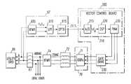
- FIG. 1illustrates the major components of a line-power unit 100 containing the inventive control devices and methods and the overall relationship to a microturbine generator.
- the microturbine generator systemincludes two major components: the turbine unit 10 and the line-power unit 100 may be arranged as shown in FIG. 1 .
- the turbine unit 10includes a motor/generator 15 and an engine control unit 12 .
- the turbine unit 10is supplied with fuel.
- the motor/generator 15may be constructed with an Allied Signal Turbo GeneratorTM which includes a turbine wheel, compressor, impeller and permanent magnet generator which are all mounted on a common shaft. This common shaft is supported by an air bearing which has a relatively high initial drag until a cushion of air is developed at which point the air bearing is nearly frictionless.
- the motor (engine) in the motor/generator 15is controlled by the engine control unit 12 which, for example, throttles the engine according to the demand placed upon the generator.
- Communicationis provided between the turbine unit 10 and the line power unit 100 as shown by the control/data line connecting these units in FIG. 1 .
- This dataincludes operating data such as turbine speed, temperature etc. as well as faults, status and turbine output.
- the motor/generator 15supplies three-phase (3 ⁇ ) electrical power to the line power unit 100 as further shown in FIG. 1 .
- the line power unit 100also supplies three-phase auxiliary power (3 ⁇ Aux) to the turbine unit 10 .
- the line power unit 100contains three basic components.
- the line power unit controller 200 , starter 220 and utility interface 240are all included within line power unit 100 .
- an operator interfacethat permits an operator to monitor and control the line power unit is further provided.
- the operator interfacemay include a front panel display for displaying critical operating data as well as controls such as a shut down switch and power level command input as further described below.
- a DC bussupplies DC power to the line power unit 100 to permit off-grid starting of the turbine unit. Furthermore, the utility interface 240 supplies three-phase electrical power to the utility grid 99 as well as an optional neutral line. The line power unit 100 also receives utility authorization from a utility company which authorizes connection to the grid 99 .
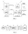
- FIG. 2illustrates a small grid-connected generation facility showing some of the details of the components controlled by this invention. More particularly, a turbine generator 15 generates AC power that is supplied to rectifier 60 . The AC power is then converted into DC power by rectifier 60 and supplied to DC link consisting of DC bus 61 and capacitor 62 connected across DC bus 61 .
- An inverter 70transforms the DC voltage on the DC link into a three-phase AC waveform that is filtered by inductor 72 and then supplied to the utility 99 via contactor K 1 .
- FIG. 2is actually a simplified diagram illustrating the necessary components for utility outage ride-through.
- Other components illustrated in FIGS. 3 and 4are necessary for other types of control exercised by the invention such as power factor and synchronization.
- FIG. 3is a system block diagram illustrating a generation facility that may be controlled according to the invention.
- the generation facilityincludes a turbine generator 15 generating AC power supplied to rectifier 60 .
- This AC poweris converted by rectifier 60 into DC voltage supplied to the DC link.
- This DC linkmay have the same construction as shown in FIG. 2 .
- the inverter 70transforms DC power from the DC link into three-phase AC power that is fed to the grid 99 via inductor unit 72 and contactor K 1 . Power may also be supplied directly to the internal loads via a connection to the output of the inverter 70 .
- the controller 200receives a sensed voltage from the DC link as well as the output AC current from the inverter 70 as inputs thereto. The controller 200 utilizes these inputs to generate control signals for the inverter 70 . More particularly, the inverter 70 is controlled by pulse width modulated (PWM) control signals generated by controller 200 to output the desired AC waveform.
- PWMpulse width modulated
- the controller 200performs feedback current control by utilizing feedback current supplied by a current sensor located at an output side the inverter 70 .
- the control exercised by the controller 200changes. Specifically, the controller 200 performs feedforward voltage control by utilizing feedforward voltage supplied by a voltage sensor located at an input side of the inverter 70 .
- These current and voltage sensors for feedback current control and feedforward voltage control, respectivelymay be part of the inverter 70 or separate therefrom as shown in FIG. 3 .
- the controller 200also outputs a disconnect control signal to contactor K 1 to control the connection of the generation facility to the utility grid 99 . Further details of the control method implemented by controller 200 are described below.
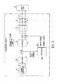
- FIG. 4illustrates the details of a line power unit 100 according to the invention.
- This line power unit (LPU) 100includes an LPU controller 200 that may be programmed according to the techniques disclosed herein.
- FIG. 4is a particularly advantageous embodiment of a line power unit 100 that may be controlled according to the invention.
- FIG. 4shows the details of the inventive line power unit 100 and its connections to the permanent magnet generator 15 , engine control unit 12 and utility grid 99 .
- the starter unit 220is generally comprised of start inverter 80 , precharge circuit 78 , transformer 76 , and transformer 82 .
- the utility interfacegenerally includes the main inverter 70 , low pass filter 72 , transformer 74 , voltage sensor 98 , and contactor K 1 .
- the LPU controller 200generally includes phase and sequence detector circuit 97 , transformer 82 , full wave rectifier 83 b , full wave rectifier 83 a , control power supply 84 and LPU controller 200 . Correspondence between the general construction shown in FIG. 1 and the detailed embodiment shown in FIG.4 is not important. This description is merely for the purpose of orienting one of ordinary skill to the inventive system.
- the permanent magnet generator 15has all three phases connected to PMG rectifier 60 .
- a DC bus 61interconnects PMG rectifier 60 and main inverter 70 .
- a capacitor 62is connected across the DC us 61 .
- the output of the main inverter 70is connected to transformer 74 via low pass LC filter 72 .
- a voltage sense circuit 98is connected to the output of the transformer 74 and supplies sensed voltages to the LPU controller 200 utilizing the data line shown.
- the voltage sense circuit 98does not interrupt the power lines as may be incorrectly implied in the drawings. Instead, the voltage sense circuit is connected across the lines between transformer 74 and contactor K 1 .
- a contactor K 1is controlled by LPU controller 200 via a control line as shown in FIG. 4 and provides a switchable connection between transformer 75 and the utility grid 99 .
- a neutral linemay be tapped from transformer 74 as further shown in FIG. 2 and connected to the grid 99 .
- a separate start inverter 80is connected to the DC bus 61 and the external DC voltage supply which may be constructed with a battery.
- the start inverter 80is also connected to the permanent magnet generator 15 .
- a precharge circuit 78is connected to the grid via transformer 76 and transformer 82 . Precharge circuit 78 is further connected to the DC bus 61 . The precharge circuit 78 has a control input connected to a control data line that terminates at the LPU controller 200 as shown.
- the line power unit 100also supplies power to a local grid (e.g., 240 VAC three phase supplying auxiliary of local loads) via transformer 74 .
- This local gridfeeds local loads and the turbine unit including pumps and fans in the turbine unit.
- An auxiliary transformer 77is also connected to the output of the transformer 74 .
- the output of the auxiliary transformer 77is fed to full wave rectifier 83 to supply full wave rectified power to the control power supply 84 .
- the control power supply 84supplies power to the engine control unit 12 and the LPU controller 200 as well as the I/O controller 310 .
- the I/O controller 310is connected via data lines to the LPU controller 200 .
- the I/O controller 310is further connected to the engine control unit 12 , display unit 250 , and LPU external interface 320 .
- the LPU external interface 320has a connection for communication and control via port 321 .
- the LPU controller 200has control lines connected to the start inverter 80 , main inverter 70 , precharge circuit 78 , transformer 82 , and contactor K 1 . Furthermore, data is also provided to the LPU controller 200 from control/data lines from these same elements as well as the phase and sequence detector 97 that is connected at the output of contactor K 1 . The LPU controller 200 also communicates data and control signals to the engine control unit 12 .
- the engine control unitis supplied power from the control power supply 84 and communicates with engine sensors as shown.
- FIG. 5 ( a )is a state diagram showing the control states and permitted control state transitions.
- the state diagram shown in FIG. 5 ( a )describes a state machine that may be implemented with the LPU controller 200 to control the line power unit 100 with the defined states and control state transitions.
- This state machineprovides mode control for the following modes of operation: initialization, neutral, pre-charge, turbine start, power on-line, power off-line, and shut down.
- the state diagram shown in FIG. 5 ( a )assumes that the line power unit 100 is mounted in an equipment cabinet having cooling fans and pumps circulating cooling fluid through cold plates.
- a cold plateis merely a device that includes a plenum through which cooling fluid is circulated and to which various power conversion devices such as the main inverter 70 and start inverter 80 are mounted. The cold plate acts as a heat sink for these devices and thereby prevents overheating.
- the alternative shown in FIG. 5 ( b )assumes that no such cabinet or cooling system is present and represents a simplified control state diagram for the invention.
- the power on/reset condition 500is not really a control state but, rather, an initial condition that triggers the state machine. This initial condition includes power on of the line power unit 100 or reset of the line power unit 100 .
- the initialization state 505occurs after reset or power on and initializes global variables, initializes the serial communication ports including the I/O controller 310 and LPU external interface 320 having serial ports contained therein, executes a built-in-test (BIT), and initializes the real-time interrupt facility and input capture interrupt within the LPU controller 200 .
- BITbuilt-in-test
- the initialization statealso starts the line synchronization techniques of the invention which are further described below as well as starting the power factor control method of the invention.
- the neutral state 510monitors commands from the I/O controller 310 and engine control unit 12 to determine the next mode of operation as well as checking critical system parameters.
- the pre-charge state 515enables the pre-charge unit 78 to charge the DC link as well as checking on the rate of charging to determine correct hardware function.
- the pre-charge state 515also performs diagnostic checks of the main inverter 70 to identify open or short type failures.
- the neutral with pre-charge complete state 520closes contactor K 1 and performs diagnostic tests of the line power unit 100 .
- the purge cabinet state 525purges the equipment cabinet in which the line power unit 100 is mounted including turning on any cooling fans and pumps and thereby bring the line power unit 100 into a purged and ready state.
- the neutral with purge complete state 530is an idle state that waits for an engine start command from the operator that is routed via port 321 to LPU external interface 320 to I/O controller 310 and thereby to LPU controller 200 .
- the start engine state 535generally performs the function of starting the engine that drives the permanent magnet generator 15 .
- the start engine state 535resets the start inverter 80 and performs basic diagnostic checks of the line power unit 100 .
- the start engine state 535also verifies the DC link voltage and thereafter sets the pulse width modulated control signal supplied to the start inverter 80 to control the maximum speed that the start inverter 80 will drive the permanent magnet generator 15 as a motor to thereby permit the engine to start.
- the start engine stateenables the start inverter 80 , receives updated speed commands from the engine control unit 12 , monitors fault signals from the start inverter 80 , and checks the speed of the engine and DC current drawn from the start inverter 80 to determine a successful start.
- the start engine state 535then waits for a signal from the engine control unit 12 to terminate the start operation which involves sending a stop signal to the start inverter 80 .
- the neutral with start complete state 540is an idle state wherein the engine is started and the permanent magnet generator 15 is being driven by the engine thereby producing three-phase power that is rectified by PMG rectifier 60 to supply DC bus 61 with DC power.
- the neutral with start complete stateessentially waits for a power level command from the operator that is routed via port 321 , LPU external interface 320 , I/O controller 310 to the LPU controller 200 .
- the power on-line state 545enables the main inverter 70 in a current mode and sends pulse width modulated control signals to the main inverter 70 to output three-phase electrical power having the commanded power level.
- the power on-line statealso performs various system checks to maintain safe operation such as verifying the DC link voltage and cold plate temperatures.
- the open contactor state 550opens the main contactor K 1 .
- the power off-line state 555switches the main inverter 70 to a voltage mode and sets the power level command to a nominal level to power the local loads.
- the power off-line statemay perform various system checks to maintain safe operation.
- the shut down state 560disables the main inverter 70 and reinitializes global variables that are utilized by the state machine to control the line power unit 100 .
- the purge cabinet state 565performs essentially the same functions as the purge cabinet state 525 and ensures that the equipment cabinet housing the line power unit 100 cools down.
- the open contactor state 570waits for a nominal cool down period such as 5 minutes as well as controlling the contactor K 1 such that it breaks the connection with the grid 99 thereby ensuring disconnection from the grid 99 .
- the clear faults state 575clears any fault codes that may have triggered the shutdown.
- the emergency stop indication 580is not actually a control state, but instead illustrates the receipt of an emergency stop signal.
- the equipment cabinet housing the line power unit 100preferably includes an emergency stop button that a user may trigger to shut down the system in an emergency.
- the open contactor state 585is triggered by the receipt of an emergency stop signal and opens main contactor K 1 thereby breaking the connection to the grid 99 .
- the state transitionsare represented in the drawings with arrows. These arrows convey important information.
- an unidirectional arrowsuch as ⁇ indicates a one-direction only permissible state transition.
- a bi-directional arrowon the other hand, such as ⁇ indicates bi-directional permissible state transitions. This may also be expressed by using the following bi-directional and unidirectional permissible state transition symbologies: (1) neutral state ⁇ pre-charge state and (2) power on-line state ⁇ power off-line state.
- the initialization state 505is triggered. After completion of the initialization procedures and successful built-in tests, the state machine permits the transition to neutral state 510 .
- the neutral state 510monitors commands from the operator and engine control unit 12 . Upon receiving an appropriate command, the state machine permits the transition to the pre-charge state 515 from the neutral state 510 .
- the pre-charge state 515triggers the pre-charge unit 78 to pre-charge the DC bus 61 to a desired pre-charge voltage.
- the pre-charge state 515determines successful pre-charge by monitoring the pre-charge rate and determining whether the pre-charge voltage is within acceptable limits at the end of the pre-charge cycle.
- the state machinetransitions back to the neutral state 510 as indicated by the fail path illustrated on FIG. 5 ( a ). Upon successful completion of the pre-charge cycle, however, the state machine permits the transition from the pre-charge state 515 to the neutral with pre-charge complete state 520 .
- the neutral with pre-charge complete state 520closes the main contactor K 1 thereby connecting the line power unit 100 to the grid 99 . Thereafter, the state machine permits the transition to the purge cabinet state 525 .
- the state machineUpon successful purging of the cabinet and passing of any diagnostic tests such as checking the cold plate temperatures, the state machine permits the transition from the purge cabinet state 525 to the neutral with purge complete state 530 . Upon receipt of a start engine command, the state machine permits the transition to the start engine state 535 .
- the start engine state 535control the start inverter 80 to drive the permanent magnet generator 15 as a motor to spin the engine at a speed to permit the engine to be started. If the engine fails to start, then the state machine transitions to the neutral with purge complete state 530 . If the engine successfully starts, then the state machine transitions to the neutral with start complete state 540 which waits for the receipt of a power level command from the operator or a remote host.
- the state machineUpon receipt of a non-zero power level command, the state machine transitions from the neutral with start complete state 540 to the power on-line state 545 .
- the state machinetransitions to the open contactor state 550 as further described in the utility outage ride-through section below.
- receipt of a zero power level commandtransitions the state machine from the power on-line state to the neutral with start complete state 540 .
- the power off-line state 555is entered. Upon completion of the power off-line procedures in power off-line state 555 , the state machine transitions to the neutral with start complete state 540 . If a shutdown command is received, the state machine then transitions to the shutdown state 560 . The shutdown state 560 is followed by the purge cabinet state 565 , open contactor state 570 and clear faults state 575 and then the neutral state 510 thereby bringing the line power unit 100 into a neutral state.
- the open contactor state 585Upon receipt of an emergency stop signal 580 , the open contactor state 585 is triggered. Thereafter, the shutdown state 560 is entered by the state machine and then the purge cabinet state 565 , open contactor state 570 , clear faults state 575 and neutral state 510 are sequentially entered by the state machine.
- FIG. 5 ( b )is a simplified state diagram that simplifies the states and state transitions illustrated in FIG. 5 ( a ).
- FIG. 5 ( b )generally assumes that there is no cabinet that needs to be purged.
- the state machine in FIG. 5 ( b )also consolidates some of the states illustrated in FIG. 5 ( a ). States having the same reference numerals are identical to those shown in FIG. 5 ( a ). The differences are pointed out below.
- the neutral with pre-charge complete state 527 shown in FIG. 5 ( b )differs from the neutral width pre-charge complete state 520 shown in FIG. 5 ( a ) essentially because the purged cabinet state 525 has been eliminated in FIG. 5 ( b ).
- the neutral with pre-charge complete state 527closes the main contactor K 1 and awaits for receipt of a start engine command from an operator or other device such as a remote host.
- the power off-line state 556 shown in FIG. 5 ( b )also differs from the power off-line state 555 shown in FIG. 5 ( a ) .
- the power off-line state 556combines the open contactor state 550 with the power off-line state 555 shown in FIG. 5 ( a ).
- the power off-line state 556performs the functions of opening the contactor K 1 , switching the main inverter 70 to a voltage mode and setting the power level to a nominal level to power the local loads.
- various system checksmay be performed to maintain safe operation.
- FIG. 5 ( b )The operation of the state machine shown in FIG. 5 ( b ) is essentially the same as that shown in FIG. 5 ( a ) with differences noted below.
- the main differenceis the consolidation of the neutral with pre-charge complete state 520 and the neutral with purge complete state 530 and the elimination of the purged cabinet state 525 from FIG. 5 ( a ).
- the pre-charge state 515successfully completes the pre-charge cycle
- the neutral with pre-charge state 527is entered by the state machine.
- the start engine state 535Upon receipt of an engine start command, the start engine state 535 is entered by the state machine. Furthermore, upon a utility outage, the state machine transitions directly from the power on-line state 545 to the power off-line state 556 as shown in FIG. 5 ( b ).
- the inventionprovides a real-time control method for controlling the line power unit 100 .
- This real-time control unitincludes specifically defined control states that ensure correct and safe operation of the line power unit 100 . Furthermore, various system checks and diagnostics are performed throughout which further ensure safe operation and which further affect state transitions.
- FIG. 6 ( a )illustrates the frequency sensing component of the frequency synthesizing apparatus and method according to the invention in relation to other components of the line power unit 100 and the utility grid 99 .
- the phase and sequence detecting circuit 97 shown 25 in FIG. 4may have the construction shown in FIG. 6 ( a ). More particularly, the sequence detector includes a transformer 605 connected to two phases A, B of the utility grid 99 . In this way, transformer 605 inputs the voltage and frequency of the utility grid 99 .
- This sensed voltage from transformer 605is supplied to a low pass filter 610 and then to an optical isolator 615 .
- the output of the optical isolator 615is a uni-polar square wave as shown in FIG. 6 ( a ) that is supplied to the line power unit controller 200 .
- the line power unit controllerincludes a vector control board 210 having an A/D converter 215 that accepts the uni-polar square wave from the optical isolator 615 .
- the A/D converterpreferably converts this uni-polar square wave into a 10-byte digital signal that is fed to the digital signal processor (DSP) 220 .
- DSPdigital signal processor
- the output of the DSP 220is fed to a pulse width modulation (PWM) signal generation device 225 .
- PWMpulse width modulation
- the pulse width modulation signals from PWM 225are fed to gate drive circuit 230 which drives the IGBT switches 71 located within the main inverter 70 .
- the main inverter 70is fed a DC voltage from DC bus 61 as shown in FIG. 4 . For simplicity, this connection is not shown in FIG. 6 ( a ).
- the output of the main inverter 70is filtered by inductor 72 . Then, the voltage is stepped up by transformer 74 and supplied to the utility grid via contactor K 1 . The output of the transformer 74 also supplies local loads as shown in FIG. 6 a.
- the frequency synchronization apparatus shown in FIG. 6 ( a )operates in the following general manner.
- the output of the optical isolator 615is a uni-polar square wave with a voltage swing preferably within the limits of the A/D converter 215 .
- the DSP 220controls the A/D converter 215 by initiating the conversion and reading of the digital value at a fixed frequency. This fixed frequency establishes the time base for which the inventive methods can compute the actual frequency of the signal and thereby the actual frequency of the utility grid 99 . This is accomplished by determining when the falling edge of the signal occurred and counting the number of samples between successive falling edges.
- the inventioncould utilize the rising edge of the signal, but for simplicity this explanation will focus on the falling edge implementation.
- FIGS. 6 ( b )-( d )illustrate various signals utilized by the invention to perform synchronization.
- FIG. 6 ( b )illustrates the SYNC signal that is the fixed frequency signal utilized by the DSP 220 to control the initiation and reading of the data from the A/D converter 215 .
- FIG. 6 ( c )illustrates the THETA signal which is a variable in software that is utilized to represent the angle of the utility sine wave and ranges from 0° to 360° in a series of stepped ramps each of which runs from 0° at the falling edge of the SYNC pulse to 360° at the next falling edge of the SYNC pulse.
- FIG. 6 ( d )illustrates THETA ⁇ which is the phase shift added to THETA for power factor control as further described below.
- the synchronization methodis further illustrated in FIGS. 7 ( a )-( b ).
- the synchronization functionis started or called every 64 microseconds at which time step 702 causes the digital signal processor 220 to read the A/D 215 input.
- the input signalis a square wave at the frequency of the grid.
- step 704sets the minimum, maximum and typical constants which are set according to the selected grid frequency.
- the grid frequencyis chosen between either 50 or 60 hertz which thereby effects the values for the minimum, maximum and typical constants in step 704 .
- FreqCountis the number of times this routine is called between falling edges of the input signal.
- step 708checks whether the FreqCount variable is out of range. If so, the Count variable is set to a typical value in step 710 and the step 712 then clears the status flag that would otherwise indicate that the line power unit 100 is in synchronization with the grid 99 . In other words, step 712 clears this status flag thereby indicating that the line power unit is not in synchronization with the grid 99 .
- step 714determines whether there is an input from the falling edge detector. Step 714 determines whether the falling edge of the synchronization pulse has occurred. If yes, then the flow proceeds to jump point A which is further illustrated in FIG. 7 ( b ).
- Step 708essentially determines whether the grid 99 is present or whether there is a utility outage. If there is utility outage, then the FreqCount variable will exceed the maximum thereby causing the system to set the count value to a typical value in step 710 .
- FIG. 7 ( b )continues the frequency synchronization process beginning with a determination of whether the frequency of the incoming signal, input is within the correct range. Particularly, step 716 determines whether the FreqCount variable is within the minimum and maximum values. If not, then step 722 sets the count variable to a typical value and then step 724 sets a status flag indicating synchronization error.
- step 718sets the Count variable equal to 360° FreqCount. Then step 720 clears the status flag indicating no synchronization error.
- step 726which resets the FreqCount variable to 0.
- step 728which checks whether THETA is substantially equal to 360° or 0°. If not, the status flag is cleared by step 732 indicating that the line power unit is not in synchronization. If yes, then step 730 sets the status flag indicating that the LPU 100 is in synchronization with grid 99 .
- step 734first determines if THETA is less than 180°. If yes, then the error variable is set to minus THETA. If not, then step 738 sets the error variable equal to 360° ⁇ THETA.
- step 736After setting the error variable in step 736 or step 738 , then the method proceeds to limit the rate of change of the Error variable.
- the preferred embodiment shown in FIG. 7 blimits the Error variable to ⁇ 0.7° in step 740 .
- step 742sets the THETA variable equal to THETA plus the Error variable.
- step 742the flow returns via jump point B to the flow shown in FIG. 7 ( a ) beginning with step 744 .
- step 746determines whether THETA is greater than 360°. If yes, step 748 resets THETA to THETA minus 360° to bring THETA within range.
- step 750determines the phase shift variable THETA ⁇ by setting THETA ⁇ equal to THETA plus any desired phase shift.
- THETA ⁇is an optional variable as is step 750 .
- step 750the synchronization function has completed its operations as indicated by end of SYNC function step 752 .
- This routineis again called after 64 microseconds have elapsed since the initiation of the SYNC function in step 700 .
- FIGS. 7 ( a ) and 7 ( b )outputs a THETA ⁇ that is utilized by a known vector algorithm in the vector board 210 to generate pulse width modulation signals from PWM 225 that are fed to gate drive 230 to thereby control the main inverter 70 .
- Such pulse width modulation control of the powercan then shift the phase of the power output from main inverter 70 and thereby bring the output power into synchronization with the utility grid 99 .
- circuit 97may also synthesize a grid frequency. This is necessary when the line power unit 100 is operating in a stand-alone mode or when the utility grid 99 is not available. Thus, the system must synthesize a frequency when the grid is temporarily disconnected so that the output power frequency is self-regulating.
- the inventive line synchronization techniquelimits the resynchronization rate in step 740 .
- the inventionprovides a smooth transition from out-of-SYNC line power unit 100 to an in-SYNC line power unit 100 that is in synchronization with the utility grid 99 . This reduces transient voltages, stress on the components and increases safety.
- this line synchronization techniquealso permits power factor control such that an operator or remote host can input a phase shift data via port 321 and thereby control the power factor of power supplied to the grid 99 .
- the state machines described in FIGS. 5 ( a )-( b )include states that are involved in the utility outage ride-through methodology. Specifically, the neutral with start complete state 540 , power on-line state 545 , open contactor state 550 , and power off-line state 555 shown in FIG. 5 ( a ) are the control states involved in the utility outage ride-through methodology.
- neutral with start complete state 540 , power on-line state 545 and power off-line state 556 shown in FIG. 5 bare alternative control states that may also be utilized by the utility outage ride-through methodology of this invention.
- the utility outage ride-through methodologymay be implemented within a controller such as the controller 200 shown in FIG. 3 or the LPU controller 200 shown in FIG. 4 .
- the utility outage ride-through methodthat may be programmed into the LPU controller 200 is shown in FIG. 8 . Furthermore, the utility outage ride-through methodology shown in FIG. 8 may be utilized by the state machine shown in FIGS. 5 a-b to control the state transitions mentioned above.
- step 800The utility outage ride-through method shown in FIG. 8 begins with step 800 . Then, steps 805 , 810 , 815 , 820 , 825 determine the existence of a fault condition. Upon the occurrence of any of these fault conditions, then the flow proceeds to open main contactor step 830 .
- step 805determines whether there is a loss of utility authorization.
- most electric utilitiessend authorization data to each electrical power generator supplying power to the grid 99 . In this way, the utility can either authorize or cancel authorization for connection to the grid 99 .
- Step 805determines whether the utility authorization has been cancelled.
- Step 810determines whether there is a loss of phase. This may be performed by sampling the input from the phase and sequence detector 97 . If any of the phases have been lost, then step 810 directs the flow to open main contactor step 830 .
- loss of synchronization step 810determines whether there is a loss of synchronization between the line power unit 100 and the grid 99 . This loss of synchronization may be determined from the status flag “LPU in SYNC” set by the synchronization method described above in relation to FIGS. 7 ( a )-( b ).
- Step 820decides whether the industrial turbo generator (ITG) host has sent an off-line command via port 321 to the LPU controller. It is not essential that an ITG host be utilized, and this step 820 may be simplified to receive any off-line command by LPU controller 200 .
- ITGindustrial turbo generator
- Step 825determines whether the AC voltage of the grid 99 is out of range.
- the voltage sense circuit 98senses this AC grid 99 voltage and sends a signal to the LPU controller 200 which can thereby determine whether the VAC is out of range in step 825 .
- step 830is executed which opens the main contactor K 1 and disconnects the line power unit 100 from the grid 99 .
- step 835resets or clears a time counter which is preferably a 30 second time counter.
- step 840sets the operational mode to off-line which causes the state machine of FIG. 5 ( a ) to transition from the open contactor state 550 to the power off-line state 555 .
- the power on-line state 545 to open contactor state 550 transitionoccurs in step 830 and is triggered by any of the fault conditions described above.
- step 845the main inverter 70 is controlled by LPU controller 200 in a voltage control mode for stand-alone operation and feeding of the local loads.
- step 850After setting the off-line voltage control in step 845 , step 850 enables the main inverter 70 to thereby supply power to the local loads. This ends the flow as indicated by step 895 .
- the systemthen continues checking the occurrence of fault conditions as described above. Continued fault conditions have the effect of clearing the 30 second counter each time.
- step 855determines whether the on-line or off-line mode (state) is being utilized by the line power unit 100 . Continuing with this example, the off-line mode is now utilized by the state machine. Thus, the mode determination step 855 directs the flow to step 860 which begins incrementing the 30 second counter.
- step 865directs the flow to off-line voltage control setting step 845 and enable three phase inverter step 850 the effect of which is to return or loop back to the increment 30 second counter step 860 .
- step 870disables the main inverter 70 .
- step 875closes main contactor K 1 thereby connecting the line power unit 100 to the grid 99 .
- the modeis set to the on-line mode which transitions the state machine from the neutral with start complete state 540 to the power on-line state 545 .
- Thisalso causes the next loop to take the left branch as determined by the mode determination step 855 which will now sense the on-line mode.
- step 855determines whether the mode is on-line. If the mode is on-line, the flow proceeds from step 855 to on-line current control step 885 which controls the main inverter 70 in a current control mode. Thereafter, step 890 enables the inverter 70 to thereby supply power to the grid 99 via closed contactor K 1 . The process is then completed as indicated by end step 895 .
- the inventionhas the capability of detecting a utility outage or other fault condition thereby triggering disconnection from the grid.
- the inventionalso provides a smooth transition from a current mode (utility connected) to a voltage mode (utility outage) for the main inverter 70 .
- the benefitis more stability and faster response to wide swings in generator voltage.
- the inventionalso has the feature of over-current limiting which is a self-protection function which prevents voltage brown-out at excessive current levels. This method also easily transitions from voltage mode to current mode when reconnecting to the grid thereby minimizing transients on power output to the grid 99 .
- the generator voltageis sampled and used to establish the modulation index of the pulse-width modulated sinusoidal voltage produced by the inverter 70 keeping the sinusoidal output voltage nearly constant.
- This control techniqueprovides the high level of stability and fast response needed for rapid changes of input voltage. Over-current protection is provided by reducing the modulation index when the maximum allowed output current is reached, producing a brown-out effect.
- the line power unit 100 voltageis first synchronized with the grid voltage. After synchronizing with the grid (as determined by step 815 and implemented by the synchronization techniques described above), normal current controlled power flow into the grid 99 can then resume.
- the systemmay be further enhanced by providing an apparatus and method for controlling the power factor of power delivered to the grid 99 .
- the synchronization control described abovealso provides power factor control
- the inventionalso provides an alternative control loop that controls the power factor.
- the power factor control device and methods according to the inventionmay be applied to a wide variety of grid-connected generation facilities as graphically illustrated by FIG. 2 .
- the current controlled inverter 70may be controlled with the device shown in FIG. 9 .
- FIG. 9illustrates a device for controlling power factor that interfaces with a current controlled inverter 70 as shown in FIG. 9 or, alternatively, the current controlled inverter 70 shown in FIGS. 2 or 4 .
- This power factor control deviceincludes a sensor 98 that senses the current supplied to the utility 99 from the inverter 70 . All three phases (I a , I b , I c ) of the current supplied to the utility 99 are sensed by sensor 98 and supplied to three-phase to two-phase transformer 905 to output two-phase D-Q coordinate signals I d , I q .
- the two-phase signals I d , I qare then supplied to a stationary-to-rotating reference frame transformation unit 910 that changes the two-phase AC signals (I d , I q ) from the stationary to a synchronously rotating reference frame which converts the signals from AC to DC.
- the DC signalsare then compared against reference signals I q Ref , I d Ref by comparators 920 and 925 , respectively.
- the comparators 920 , 925are preferably proportional-plus-integral gain stages that perform proportional-plus-integral comparison operations between the reference signals I q Ref , I d Ref and the DC signals I d , I q .
- the reference signals I q Ref , I d Refmay be supplied by the LPU controller 200 which, in turn, may be supplied these reference signals from an operator via port 321 , LPU external interface 320 , I/O controller 310 . In this way, either the LPU controller 200 or the operator can command the power factor.
- the utilitymay also request a certain power factor to be supplied to the grid 99 by the line power unit 100 .
- a requestcan be fed to the system via the reference signals I q Ref , I d Ref .
- the proportional plus integral gain stages 920 , 925output voltage signals V q , V d that are transformed back to a stationary reference frame by rotating to stationary reference frame transforming unit 930 to output AC voltages V q , V d .
- These AC voltagesare then subjected to a two-phase to three-phase transform by unit 935 to thereby output three-phase voltages V a , V b , V c which are then sent to a pulse width modulator which controls the switches in a three-phase, full-wave IGBT bridge within the inverter 70 to produce AC currents (I a , I b , I c ) with a vector that contains the real and reactive components commanded by I d Ref and I q Ref .
- This power factor control loopprovides independent control of the real and reactive components of the current output to utility 99 .
- This inventiondraws upon widely known vector control techniques developed for induction motor drives.
- the desired amplitudes of real and reactive current supplied to the utility 99are commanded by I q ref and I d ref , respectively.
- the control loop described abovedrives the output current to the utility (I a , I b , I c ) so that the magnitude and phase contain the commanded real and reactive current components.
- the utility interface 99may also be a local grid.
- Such a local gridmay also require power factor correction due to large inductive or capacitive loads on the local grid.
- the poor power factor that such large inductive or capacitive loads causemay be corrected by utilizing the power factor control method and apparatus disclosed herein.
Landscapes
- Engineering & Computer Science (AREA)
- Power Engineering (AREA)
- Control Of Eletrric Generators (AREA)
- Stand-By Power Supply Arrangements (AREA)
- Inverter Devices (AREA)
- Oscillators With Electromechanical Resonators (AREA)
- Networks Using Active Elements (AREA)
Abstract
Description
Claims (11)
Priority Applications (3)
| Application Number | Priority Date | Filing Date | Title |
|---|---|---|---|
| US09/535,541US6316918B1 (en) | 1998-08-26 | 2000-03-27 | Integrated control system and method for controlling mode, synchronization, power factor, and utility outage ride-through for micropower generation systems |
| US09/900,849US6380719B2 (en) | 1998-08-26 | 2001-07-03 | Integrated control system and method for controlling mode, synchronization, power factor, and utility outage ride-through for micropower generation systems |
| US09/907,886US6411065B1 (en) | 1998-08-26 | 2001-08-20 | Integrated control system and method for controlling mode, synchronization, power factor, and utility outage ride through for micropower generation systems |
Applications Claiming Priority (2)
| Application Number | Priority Date | Filing Date | Title |
|---|---|---|---|
| US09/140,391US6072302A (en) | 1998-08-26 | 1998-08-26 | Integrated control system and method for controlling mode, synchronization, power factor, and utility outage ride-through for micropower generation systems |
| US09/535,541US6316918B1 (en) | 1998-08-26 | 2000-03-27 | Integrated control system and method for controlling mode, synchronization, power factor, and utility outage ride-through for micropower generation systems |
Related Parent Applications (1)
| Application Number | Title | Priority Date | Filing Date |
|---|---|---|---|
| US09/140,391DivisionUS6072302A (en) | 1998-08-26 | 1998-08-26 | Integrated control system and method for controlling mode, synchronization, power factor, and utility outage ride-through for micropower generation systems |
Related Child Applications (1)
| Application Number | Title | Priority Date | Filing Date |
|---|---|---|---|
| US09/900,849DivisionUS6380719B2 (en) | 1998-08-26 | 2001-07-03 | Integrated control system and method for controlling mode, synchronization, power factor, and utility outage ride-through for micropower generation systems |
Publications (1)
| Publication Number | Publication Date |
|---|---|
| US6316918B1true US6316918B1 (en) | 2001-11-13 |
Family
ID=22491027
Family Applications (4)
| Application Number | Title | Priority Date | Filing Date |
|---|---|---|---|
| US09/140,391Expired - LifetimeUS6072302A (en) | 1998-08-26 | 1998-08-26 | Integrated control system and method for controlling mode, synchronization, power factor, and utility outage ride-through for micropower generation systems |
| US09/535,541Expired - LifetimeUS6316918B1 (en) | 1998-08-26 | 2000-03-27 | Integrated control system and method for controlling mode, synchronization, power factor, and utility outage ride-through for micropower generation systems |
| US09/900,849Expired - LifetimeUS6380719B2 (en) | 1998-08-26 | 2001-07-03 | Integrated control system and method for controlling mode, synchronization, power factor, and utility outage ride-through for micropower generation systems |
| US09/907,886Expired - LifetimeUS6411065B1 (en) | 1998-08-26 | 2001-08-20 | Integrated control system and method for controlling mode, synchronization, power factor, and utility outage ride through for micropower generation systems |
Family Applications Before (1)
| Application Number | Title | Priority Date | Filing Date |
|---|---|---|---|
| US09/140,391Expired - LifetimeUS6072302A (en) | 1998-08-26 | 1998-08-26 | Integrated control system and method for controlling mode, synchronization, power factor, and utility outage ride-through for micropower generation systems |
Family Applications After (2)
| Application Number | Title | Priority Date | Filing Date |
|---|---|---|---|
| US09/900,849Expired - LifetimeUS6380719B2 (en) | 1998-08-26 | 2001-07-03 | Integrated control system and method for controlling mode, synchronization, power factor, and utility outage ride-through for micropower generation systems |
| US09/907,886Expired - LifetimeUS6411065B1 (en) | 1998-08-26 | 2001-08-20 | Integrated control system and method for controlling mode, synchronization, power factor, and utility outage ride through for micropower generation systems |
Country Status (5)
| Country | Link |
|---|---|
| US (4) | US6072302A (en) |
| EP (1) | EP1099290B1 (en) |
| AT (1) | ATE238624T1 (en) |
| DE (1) | DE69907204T2 (en) |
| WO (1) | WO2000013285A2 (en) |
Cited By (34)
| Publication number | Priority date | Publication date | Assignee | Title |
|---|---|---|---|---|
| US20020024323A1 (en)* | 2000-08-28 | 2002-02-28 | Honda Giken Kogyo Kabushiki Kaisha | Engine generator apparatus |
| US6380719B2 (en)* | 1998-08-26 | 2002-04-30 | Satcon Technology Corporation | Integrated control system and method for controlling mode, synchronization, power factor, and utility outage ride-through for micropower generation systems |
| US6466465B1 (en)* | 2000-02-14 | 2002-10-15 | Liebert Corporation | Digital control of voltage harmonic distortion and overload current protection for inverters |
| US6498462B2 (en)* | 2001-02-05 | 2002-12-24 | Plug Power Inc. | Generator control system to accommodate a decrease in a power grid voltage |
| US20030071588A1 (en)* | 2001-09-04 | 2003-04-17 | Yoshitaka Iwaji | System for driving electric motor |
| US20030163296A1 (en)* | 2002-02-28 | 2003-08-28 | Zetacon Corporation | Predictive control system and method |
| US20040008010A1 (en)* | 2002-06-18 | 2004-01-15 | Mohammed Ebrahim | Microturbine engine system |
| US20040075424A1 (en)* | 2000-12-22 | 2004-04-22 | David Chadwick | Waveform control system |
| US20040130216A1 (en)* | 2001-03-12 | 2004-07-08 | Beckers Gerardus Jacobus Josephine | Connecting circuit and method for connecting a generator to the electricity grid making use thereof |
| US20050040794A1 (en)* | 2003-08-18 | 2005-02-24 | Tracy Mark D. | Control system for a sputtering system |
| US20060066112A1 (en)* | 2001-12-31 | 2006-03-30 | Geis Everett R | Turbogenerator/motor controller with ancillary energy storage/discharge |
| US7081734B1 (en)* | 2005-09-02 | 2006-07-25 | York International Corporation | Ride-through method and system for HVACandR chillers |
| US20070005195A1 (en)* | 2005-01-10 | 2007-01-04 | Nicholas Pasquale | Distributed energy storage for reducing power demand |
| US20070007929A1 (en)* | 2005-07-07 | 2007-01-11 | Kevin Lee | System and method of controlling power to a non-motor load |
| US20070076341A1 (en)* | 2005-09-30 | 2007-04-05 | Lee Ping S | Brownout ride-through system and method |
| US20070252551A1 (en)* | 2004-02-05 | 2007-11-01 | Dyson Technology Limited | Control of Electrical Machines |
| US20070278983A1 (en)* | 2004-02-05 | 2007-12-06 | Dyson Technology Limited | Control of Electrical Machines |
| US20080061629A1 (en)* | 2006-09-13 | 2008-03-13 | Cummins Power Generation Inc. | Method of providing generator set standby power |
| US20090058191A1 (en)* | 2007-08-30 | 2009-03-05 | Briggs And Stratton Corporation | Transfer switch |
| US20090174186A1 (en)* | 2006-09-14 | 2009-07-09 | Anders Nyborg | Method For Controlling A Wind Turbine Connected To The Utility Grid, Wind Turbine And Wind Park |
| US20090241592A1 (en)* | 2007-10-05 | 2009-10-01 | Emerson Climate Technologies, Inc. | Compressor assembly having electronics cooling system and method |
| US20100138061A1 (en)* | 2009-10-20 | 2010-06-03 | General Electric Company | System and method for decreasing solar collector system losses |
| US20100133904A1 (en)* | 2009-10-26 | 2010-06-03 | General Electric Company | Dc bus voltage control for two stage solar converter |
| US20110129354A1 (en)* | 2007-10-05 | 2011-06-02 | Emerson Climate Technologies, Inc. | Vibration Protection In A Variable Speed Compressor |
| US20110205773A1 (en)* | 2010-02-24 | 2011-08-25 | General Electric Company | Method and system to allow for high dc source voltage with lower dc link voltage in a two stage power converter |
| US8418483B2 (en) | 2007-10-08 | 2013-04-16 | Emerson Climate Technologies, Inc. | System and method for calculating parameters for a refrigeration system with a variable speed compressor |
| US8448459B2 (en) | 2007-10-08 | 2013-05-28 | Emerson Climate Technologies, Inc. | System and method for evaluating parameters for a refrigeration system with a variable speed compressor |
| US8459053B2 (en) | 2007-10-08 | 2013-06-11 | Emerson Climate Technologies, Inc. | Variable speed compressor protection system and method |
| US8539786B2 (en) | 2007-10-08 | 2013-09-24 | Emerson Climate Technologies, Inc. | System and method for monitoring overheat of a compressor |
| US8950206B2 (en) | 2007-10-05 | 2015-02-10 | Emerson Climate Technologies, Inc. | Compressor assembly having electronics cooling system and method |
| US9541907B2 (en) | 2007-10-08 | 2017-01-10 | Emerson Climate Technologies, Inc. | System and method for calibrating parameters for a refrigeration system with a variable speed compressor |
| US11139948B2 (en)* | 2017-06-15 | 2021-10-05 | Korea Electric Power Corporation | AMI system for performing phase detection and synchronization in AMI communication network using relay communication method, and method thereof |
| US11206743B2 (en) | 2019-07-25 | 2021-12-21 | Emerson Climate Technolgies, Inc. | Electronics enclosure with heat-transfer element |
| US20240106684A1 (en)* | 2022-09-26 | 2024-03-28 | Gigadevice Semiconductor Inc. | Frequency-detecting circuit and electronic device |
Families Citing this family (199)
| Publication number | Priority date | Publication date | Assignee | Title |
|---|---|---|---|---|
| AU6638400A (en)* | 1999-08-16 | 2001-03-13 | Coleman Powermate, Inc. | System that supplies electrical power and compressed air |
| EP1130766B1 (en)* | 1999-09-10 | 2014-02-19 | Mitsubishi Denki Kabushiki Kaisha | Automotive dynamo controller |
| FR2804254B1 (en)* | 2000-01-26 | 2002-05-31 | Air Liquide | IMPROVED METHOD FOR PROVIDING ELECTRIC POWER TO THE NETWORK USING AN AC GENERATOR ASSOCIATED WITH A TURBINE |
| ES2333199T3 (en)* | 2000-01-28 | 2010-02-18 | Cummins Generator Technologies Limited | AC POWER GENERATOR SYSTEM. |
| US6700214B2 (en)* | 2000-02-14 | 2004-03-02 | Aura Systems, Inc. | Mobile power generation system |
| US6759764B1 (en) | 2000-07-05 | 2004-07-06 | Hybrid Power Generation Systems Llc | Grid load logic |
| US6410992B1 (en)* | 2000-08-23 | 2002-06-25 | Capstone Turbine Corporation | System and method for dual mode control of a turbogenerator/motor |
| US20020036430A1 (en)* | 2000-09-28 | 2002-03-28 | Welches Richard S. | Local area grid for distributed power |
| DE10059018C2 (en)* | 2000-11-28 | 2002-10-24 | Aloys Wobben | Wind turbine or wind farm consisting of a large number of wind turbines |
| US20020167174A1 (en)* | 2001-05-09 | 2002-11-14 | Haass Michael A. | Portable generator for commucications systems |
| KR20040007652A (en) | 2001-06-05 | 2004-01-24 | 윌리암 디. 맥다니엘 | Automatic power factor correction system |
| US6462519B1 (en)* | 2001-06-05 | 2002-10-08 | Mcdaniel William D. | Automatic power factor correction system |
| US7002321B2 (en)* | 2001-06-05 | 2006-02-21 | Mcdaniel William D | Automatic power factor correction using power measurement chip |
| US6631080B2 (en) | 2001-06-06 | 2003-10-07 | Hybrid Power Generation Systems Llc | Systems and methods for boosting DC link voltage in turbine generators |
| US6727603B1 (en) | 2001-08-07 | 2004-04-27 | Hybrid Power Generation Systems Llc | Automatic mode transitions for microturbine generating systems |
| EP2275674B2 (en) | 2001-09-28 | 2023-09-06 | Wobben Properties GmbH | Method for operating a wind park |
| US6703718B2 (en) | 2001-10-12 | 2004-03-09 | David Gregory Calley | Wind turbine controller |
| US6586914B2 (en)* | 2001-11-19 | 2003-07-01 | General Electric Company | Wound field synchronous machine control system and method |
| AU2002354106A1 (en)* | 2001-12-07 | 2003-06-30 | Ebara Corporation | Turbine generator start method and turbine generation system |
| AU2002258715A1 (en)* | 2002-04-04 | 2003-10-20 | Illusion Technologies, Llc | Miniature/micro scale power generation system |
| US6924563B2 (en)* | 2002-05-31 | 2005-08-02 | General Electric Company | Method and apparatus for controlling a microturbine |
| US7309928B2 (en)* | 2002-06-06 | 2007-12-18 | Black & Decker Inc. | Starter system for portable internal combustion engine electric generators using a portable universal battery pack |
| US7989969B2 (en) | 2002-06-06 | 2011-08-02 | Black & Decker Inc. | Universal power tool battery pack coupled to a portable internal combustion engine |
| US8319357B2 (en)* | 2002-06-06 | 2012-11-27 | Black & Decker Inc. | Starter system for portable internal combustion engine electric generators using a portable universal battery pack |
| US7687926B2 (en)* | 2002-06-06 | 2010-03-30 | Black & Decker Inc. | Starter system for portable internal combustion engine electric generators using a portable universal battery pack |
| WO2003105331A2 (en)* | 2002-06-06 | 2003-12-18 | Black & Decker Inc. | Starter system for portable internal combustion engine electric generators using a portable universal battery pack |
| US6703719B1 (en)* | 2002-08-28 | 2004-03-09 | General Electric Company | Systems and methods for managing a battery source associated with a microturbine power generating system |
| KR20040034908A (en)* | 2002-10-17 | 2004-04-29 | 엘지전자 주식회사 | Driving apparatus of three phase induction motor |
| JP4249134B2 (en)* | 2002-11-15 | 2009-04-02 | ゼファー株式会社 | Wind power generator |
| EP1570561B1 (en)* | 2002-12-10 | 2010-04-14 | Ebara Corporation | Interconnecting power generation system |
| US6775156B1 (en)* | 2003-04-08 | 2004-08-10 | Compal Electronics Inc. | Power limitation transformer circuit structure of power supply |
| US6798159B1 (en)* | 2003-04-14 | 2004-09-28 | Carrier Corporation | VSD control |
| WO2004098261A2 (en)* | 2003-05-02 | 2004-11-18 | Xantrex Technology Inc. | Control system for doubly fed induction generator |
| US7233129B2 (en)* | 2003-05-07 | 2007-06-19 | Clipper Windpower Technology, Inc. | Generator with utility fault ride-through capability |
| US7078880B2 (en)* | 2003-08-15 | 2006-07-18 | Honeywell International, Inc. | Energy storage flywheel voltage regulation and load sharing system and method |
| JP4433149B2 (en)* | 2003-10-31 | 2010-03-17 | 国産電機株式会社 | Engine-driven inverter power generator and control method thereof |
| GB0326070D0 (en)* | 2003-11-07 | 2003-12-10 | Newage Int Ltd | An AC power generating system |
| WO2005052362A2 (en)* | 2003-11-19 | 2005-06-09 | Wind Save Limited | Renewable energy resources |
| US7183667B2 (en)* | 2003-12-19 | 2007-02-27 | Square D Company | Method and apparatus for power inverter synchronization |
| DE10360462A1 (en)* | 2003-12-22 | 2005-07-14 | Repower Systems Ag | Wind energy plant with an autonomous control device with a reactive power and reactive power control module |
| JP4269941B2 (en)* | 2004-01-08 | 2009-05-27 | 株式会社日立製作所 | Wind power generator and control method thereof |
| EP1761984B1 (en)* | 2004-03-16 | 2013-03-27 | Tecogen, Inc. | Engine driven power inverter system with cogeneration |
| US7038423B2 (en)* | 2004-05-07 | 2006-05-02 | Bay Controls, Inc. | Apparatus and method for ride through for AC induction motors |
| FI119579B (en)* | 2004-08-13 | 2008-12-31 | Abb Oy | Procedure in a frequency converter with voltage intermediate circuit and frequency converter |
| US7417336B2 (en)* | 2004-08-31 | 2008-08-26 | Caterpillar Inc. | Combination current hysteresis and voltage hysteresis control for a power converter |
| US7116067B2 (en)* | 2004-09-21 | 2006-10-03 | Honeywell International Inc. | Power converter controlling apparatus and method providing ride through capability during power interruption in a motor drive system |
| US7202638B2 (en)* | 2004-10-15 | 2007-04-10 | General Electric Company | Anti-islanding protection systems for synchronous machine based distributed generators |
| EP1691463A1 (en)* | 2005-02-09 | 2006-08-16 | Magnetek S.p.A. | Method and device for the control of a three-phase inverter |
| CH697550B1 (en)* | 2005-03-30 | 2008-11-28 | Alstom Technology Ltd | Method for controlling a frequency converter. |
| JP4080493B2 (en)* | 2005-04-21 | 2008-04-23 | 三菱電機株式会社 | Control device for vehicle generator |
| US7208891B2 (en)* | 2005-05-06 | 2007-04-24 | York International Corp. | Variable speed drive for a chiller system |
| US7321834B2 (en)* | 2005-07-15 | 2008-01-22 | Chang Gung University | Method for calculating power flow solution of a power transmission network that includes interline power flow controller (IPFC) |
| ES2265771B1 (en)* | 2005-07-22 | 2008-01-16 | GAMESA INNOVATION & TECHNOLOGY, S.L. | METHOD FOR MAINTAINING THE COMPONENTS OF A WIND TURBINE AND A WIND TURBINE WITH COMPONENTS THAT ALLOW OPERATING MAINTENANCE. |
| US7468595B2 (en)* | 2005-07-26 | 2008-12-23 | Eaton Corporation | System and method of controlling the start-up of an adjustable speed motor drive based sinusoidal output power conditioner |
| RU2364016C1 (en)* | 2005-08-18 | 2009-08-10 | Сименс Энерджи Энд Отомейшн, Инк. | System and method of limiting alternating inrush current |
| US7449853B2 (en)* | 2005-09-01 | 2008-11-11 | Gm Global Technology Operations, Inc. | High power, low noise interconnection for an integrated dual wound motor to a dual inverter |
| US20070046224A1 (en)* | 2005-09-01 | 2007-03-01 | Korich Mark D | High power, low EMI noise interconnection for connecting an electric motor to an inverter |
| US7332885B2 (en)* | 2005-09-02 | 2008-02-19 | Johnson Controls Technology Company | Ride-through method and system for HVAC&R chillers |
| US11881814B2 (en) | 2005-12-05 | 2024-01-23 | Solaredge Technologies Ltd. | Testing of a photovoltaic panel |
| US10693415B2 (en) | 2007-12-05 | 2020-06-23 | Solaredge Technologies Ltd. | Testing of a photovoltaic panel |
| KR100768849B1 (en) | 2005-12-06 | 2007-10-22 | 엘지전자 주식회사 | Power supply system and method for grid-connected fuel cell system |
| US20070151272A1 (en)* | 2006-01-03 | 2007-07-05 | York International Corporation | Electronic control transformer using DC link voltage |
| US7505833B2 (en)* | 2006-03-29 | 2009-03-17 | General Electric Company | System, method, and article of manufacture for controlling operation of an electrical power generation system |
| US7391126B2 (en)* | 2006-06-30 | 2008-06-24 | General Electric Company | Systems and methods for an integrated electrical sub-system powered by wind energy |
| WO2008031433A1 (en)* | 2006-09-14 | 2008-03-20 | Vestas Wind Systems A/S | Methods for controlling a wind turbine connected to the utility grid, wind turbine and wind park |
| US7417333B2 (en)* | 2006-11-02 | 2008-08-26 | General Electric Company | Methods and apparatus for controlling current in an electrical machine |
| US11735910B2 (en) | 2006-12-06 | 2023-08-22 | Solaredge Technologies Ltd. | Distributed power system using direct current power sources |
| US9130401B2 (en) | 2006-12-06 | 2015-09-08 | Solaredge Technologies Ltd. | Distributed power harvesting systems using DC power sources |
| US8963369B2 (en) | 2007-12-04 | 2015-02-24 | Solaredge Technologies Ltd. | Distributed power harvesting systems using DC power sources |
| US8319483B2 (en) | 2007-08-06 | 2012-11-27 | Solaredge Technologies Ltd. | Digital average input current control in power converter |
| US12316274B2 (en) | 2006-12-06 | 2025-05-27 | Solaredge Technologies Ltd. | Pairing of components in a direct current distributed power generation system |
| US9112379B2 (en) | 2006-12-06 | 2015-08-18 | Solaredge Technologies Ltd. | Pairing of components in a direct current distributed power generation system |
| US8319471B2 (en) | 2006-12-06 | 2012-11-27 | Solaredge, Ltd. | Battery power delivery module |
| US8618692B2 (en) | 2007-12-04 | 2013-12-31 | Solaredge Technologies Ltd. | Distributed power system using direct current power sources |
| US11296650B2 (en) | 2006-12-06 | 2022-04-05 | Solaredge Technologies Ltd. | System and method for protection during inverter shutdown in distributed power installations |
| US11855231B2 (en) | 2006-12-06 | 2023-12-26 | Solaredge Technologies Ltd. | Distributed power harvesting systems using DC power sources |
| US11309832B2 (en) | 2006-12-06 | 2022-04-19 | Solaredge Technologies Ltd. | Distributed power harvesting systems using DC power sources |
| US8473250B2 (en) | 2006-12-06 | 2013-06-25 | Solaredge, Ltd. | Monitoring of distributed power harvesting systems using DC power sources |
| US11687112B2 (en) | 2006-12-06 | 2023-06-27 | Solaredge Technologies Ltd. | Distributed power harvesting systems using DC power sources |
| US8013472B2 (en) | 2006-12-06 | 2011-09-06 | Solaredge, Ltd. | Method for distributed power harvesting using DC power sources |
| US8384243B2 (en) | 2007-12-04 | 2013-02-26 | Solaredge Technologies Ltd. | Distributed power harvesting systems using DC power sources |
| US8816535B2 (en) | 2007-10-10 | 2014-08-26 | Solaredge Technologies, Ltd. | System and method for protection during inverter shutdown in distributed power installations |
| US8947194B2 (en) | 2009-05-26 | 2015-02-03 | Solaredge Technologies Ltd. | Theft detection and prevention in a power generation system |
| US9088178B2 (en) | 2006-12-06 | 2015-07-21 | Solaredge Technologies Ltd | Distributed power harvesting systems using DC power sources |
| US11569659B2 (en) | 2006-12-06 | 2023-01-31 | Solaredge Technologies Ltd. | Distributed power harvesting systems using DC power sources |
| US11888387B2 (en) | 2006-12-06 | 2024-01-30 | Solaredge Technologies Ltd. | Safety mechanisms, wake up and shutdown methods in distributed power installations |
| EP2533258B1 (en)* | 2006-12-20 | 2014-11-05 | Analogic Corporation | Non-contact rotary power transfer system |
| ITTO20070016A1 (en)* | 2007-01-11 | 2008-07-12 | Indesit Co Spa | METHOD FOR MEASURING THE FREQUENCY OF NETWORK AND THE ELECTRICAL UTILITY THAT IMPLEMENTS THIS METHOD |
| US8014110B2 (en) | 2007-01-22 | 2011-09-06 | Johnson Controls Technology Company | Variable speed drive with integral bypass contactor |
| US8149579B2 (en)* | 2008-03-28 | 2012-04-03 | Johnson Controls Technology Company | Cooling member |
| US8495890B2 (en)* | 2007-01-22 | 2013-07-30 | Johnson Controls Technology Company | Cooling member |
| US7782626B2 (en) | 2007-02-02 | 2010-08-24 | Black & Decker Inc. | Portable power driven system with battery anti-theft apparatus |
| US8511073B2 (en)* | 2010-04-14 | 2013-08-20 | Stewart Kaiser | High efficiency cogeneration system and related method of use |
| US8004803B2 (en) | 2007-05-08 | 2011-08-23 | Johnson Controls Technology Company | Variable speed drive |
| US8258761B2 (en)* | 2007-07-31 | 2012-09-04 | Battelle Memorial Institute | Electrical energy consumption control apparatuses and electrical energy consumption control methods |
| DE102007042528B4 (en)* | 2007-09-07 | 2018-06-14 | Sew-Eurodrive Gmbh & Co Kg | System and method for precharging a DC link capacitor |
| US7957166B2 (en)* | 2007-10-30 | 2011-06-07 | Johnson Controls Technology Company | Variable speed drive |
| US8174853B2 (en)* | 2007-10-30 | 2012-05-08 | Johnson Controls Technology Company | Variable speed drive |
| US11264947B2 (en) | 2007-12-05 | 2022-03-01 | Solaredge Technologies Ltd. | Testing of a photovoltaic panel |
| CN105244905B (en)* | 2007-12-05 | 2019-05-21 | 太阳能安吉有限公司 | Release mechanism in distributed power device is waken up and method for closing |
| WO2009072076A2 (en) | 2007-12-05 | 2009-06-11 | Solaredge Technologies Ltd. | Current sensing on a mosfet |
| US9291696B2 (en) | 2007-12-05 | 2016-03-22 | Solaredge Technologies Ltd. | Photovoltaic system power tracking method |
| EP2225778B1 (en) | 2007-12-05 | 2019-06-26 | Solaredge Technologies Ltd. | Testing of a photovoltaic panel |
| WO2009073867A1 (en) | 2007-12-05 | 2009-06-11 | Solaredge, Ltd. | Parallel connected inverters |
| US7813884B2 (en)* | 2008-01-14 | 2010-10-12 | Chang Gung University | Method of calculating power flow solution of a power grid that includes generalized power flow controllers |
| US8111052B2 (en) | 2008-03-24 | 2012-02-07 | Solaredge Technologies Ltd. | Zero voltage switching |
| US8154892B2 (en)* | 2008-04-02 | 2012-04-10 | Arraypower, Inc. | Method for controlling electrical power |
| EP2294669B8 (en) | 2008-05-05 | 2016-12-07 | Solaredge Technologies Ltd. | Direct current power combiner |
| CN101582592B (en)* | 2008-05-15 | 2013-07-10 | 宣昆 | Transformer-less photovoltaic merging and inverting device and control method thereof |
| US8353174B1 (en) | 2008-10-03 | 2013-01-15 | Johnson Controls Technology Company | Control method for vapor compression system |
| US8693228B2 (en)* | 2009-02-19 | 2014-04-08 | Stefan Matan | Power transfer management for local power sources of a grid-tied load |
| US8912672B2 (en) | 2009-05-20 | 2014-12-16 | Cummins Power Generator IP, Inc. | Control of an engine-driven generator to address transients of an electrical power grid connected thereto |
| EP2602831B1 (en) | 2009-05-22 | 2014-07-16 | Solaredge Technologies Ltd. | Electrically isolated heat dissipating junction box |
| US8264192B2 (en) | 2009-08-10 | 2012-09-11 | Emerson Climate Technologies, Inc. | Controller and method for transitioning between control angles |
| US8476873B2 (en)* | 2009-08-10 | 2013-07-02 | Emerson Climate Technologies, Inc. | System and method for current balancing |
| US8264860B2 (en)* | 2009-08-10 | 2012-09-11 | Emerson Climate Technologies, Inc. | System and method for power factor correction frequency tracking and reference generation |
| US8508166B2 (en)* | 2009-08-10 | 2013-08-13 | Emerson Climate Technologies, Inc. | Power factor correction with variable bus voltage |
| US8406021B2 (en)* | 2009-08-10 | 2013-03-26 | Emerson Climate Technologies, Inc. | System and method for reducing line current distortion |
| US8698433B2 (en) | 2009-08-10 | 2014-04-15 | Emerson Climate Technologies, Inc. | Controller and method for minimizing phase advance current |
| US8493014B2 (en)* | 2009-08-10 | 2013-07-23 | Emerson Climate Technologies, Inc. | Controller and method for estimating, managing, and diagnosing motor parameters |
| US8358098B2 (en)* | 2009-08-10 | 2013-01-22 | Emerson Climate Technologies, Inc. | System and method for power factor correction |
| US8344706B2 (en)* | 2009-08-10 | 2013-01-01 | Emerson Climate Technologies, Inc. | System and method for rejecting DC current in power factor correction systems |
| US8482156B2 (en)* | 2009-09-09 | 2013-07-09 | Array Power, Inc. | Three phase power generation from a plurality of direct current sources |
| US7888915B2 (en)* | 2009-09-11 | 2011-02-15 | General Electric Company | System for detecting generator winding faults |
| US9252601B2 (en)* | 2009-09-24 | 2016-02-02 | Vestas Wind Systems A/S | Method for controlling a power converter in a wind turbine generator |
| US12418177B2 (en) | 2009-10-24 | 2025-09-16 | Solaredge Technologies Ltd. | Distributed power system using direct current power sources |
| US8710699B2 (en)* | 2009-12-01 | 2014-04-29 | Solaredge Technologies Ltd. | Dual use photovoltaic system |
| KR101599555B1 (en)* | 2009-12-24 | 2016-03-03 | 두산인프라코어 주식회사 | Power converter for hybrid |
| US8766696B2 (en) | 2010-01-27 | 2014-07-01 | Solaredge Technologies Ltd. | Fast voltage level shifter circuit |
| WO2011140559A1 (en)* | 2010-05-07 | 2011-11-10 | Advanced Energy Industries, Inc. | Systems and methods for islanding detection |
| JP5589085B2 (en)* | 2010-09-22 | 2014-09-10 | 東芝三菱電機産業システム株式会社 | Power converter |
| US10230310B2 (en) | 2016-04-05 | 2019-03-12 | Solaredge Technologies Ltd | Safety switch for photovoltaic systems |
| US10673222B2 (en) | 2010-11-09 | 2020-06-02 | Solaredge Technologies Ltd. | Arc detection and prevention in a power generation system |
| US10673229B2 (en) | 2010-11-09 | 2020-06-02 | Solaredge Technologies Ltd. | Arc detection and prevention in a power generation system |
| GB2485527B (en) | 2010-11-09 | 2012-12-19 | Solaredge Technologies Ltd | Arc detection and prevention in a power generation system |
| DK2461026T4 (en)* | 2010-12-03 | 2017-03-13 | Siemens Ag | Device and method for testing a system for producing electricity |
| GB2486408A (en) | 2010-12-09 | 2012-06-20 | Solaredge Technologies Ltd | Disconnection of a string carrying direct current |
| GB2483317B (en) | 2011-01-12 | 2012-08-22 | Solaredge Technologies Ltd | Serially connected inverters |
| EP2695291A4 (en) | 2011-01-17 | 2017-05-24 | Kent Kernahan | Idealized solar panel |
| KR101920296B1 (en)* | 2011-01-26 | 2018-11-21 | 페어차일드코리아반도체 주식회사 | Switch control circuit, switch controlling method, and power supply device using the switch control circuit |
| DE102011000459B4 (en)* | 2011-02-02 | 2017-11-02 | Universität Kassel | Method for supplying reactive current with a converter and converter arrangement and energy supply system |
| US9293924B2 (en)* | 2011-02-15 | 2016-03-22 | Raytheon Company | Electrical phase synchronization |
| US20130009700A1 (en)* | 2011-07-08 | 2013-01-10 | Infineon Technologies Ag | Power Converter Circuit with AC Output |
| US8570005B2 (en) | 2011-09-12 | 2013-10-29 | Solaredge Technologies Ltd. | Direct current link circuit |
| US9203323B2 (en)* | 2011-09-22 | 2015-12-01 | Renewable Power Conversion, Inc. | Very high efficiency uninterruptible power supply |
| WO2013060019A1 (en)* | 2011-10-28 | 2013-05-02 | General Electric Company | Systems and methods for using in identifying and responding to type of grid fault event |
| US9112430B2 (en) | 2011-11-03 | 2015-08-18 | Firelake Acquisition Corp. | Direct current to alternating current conversion utilizing intermediate phase modulation |
| GB2498365A (en) | 2012-01-11 | 2013-07-17 | Solaredge Technologies Ltd | Photovoltaic module |
| WO2013108288A1 (en)* | 2012-01-18 | 2013-07-25 | 株式会社 日立製作所 | Wind power generating system |
| US9853565B2 (en) | 2012-01-30 | 2017-12-26 | Solaredge Technologies Ltd. | Maximized power in a photovoltaic distributed power system |
| GB2498790A (en) | 2012-01-30 | 2013-07-31 | Solaredge Technologies Ltd | Maximising power in a photovoltaic distributed power system |
| GB2498791A (en) | 2012-01-30 | 2013-07-31 | Solaredge Technologies Ltd | Photovoltaic panel circuitry |
| CN102714464B (en)* | 2012-02-29 | 2014-04-02 | 深圳市核达中远通电源技术有限公司 | A multi-input DC converter and a PFC circuit |
| GB2499991A (en) | 2012-03-05 | 2013-09-11 | Solaredge Technologies Ltd | DC link circuit for photovoltaic array |
| CN103312184B (en)* | 2012-03-09 | 2015-09-16 | 台达电子工业股份有限公司 | A power circuit, a converter structure and a wind power generation system thereof |
| US9634593B2 (en) | 2012-04-26 | 2017-04-25 | Emerson Climate Technologies, Inc. | System and method for permanent magnet motor control |
| EP3499695B1 (en) | 2012-05-25 | 2024-09-18 | Solaredge Technologies Ltd. | Circuit for interconnected direct current power sources |
| US10115841B2 (en) | 2012-06-04 | 2018-10-30 | Solaredge Technologies Ltd. | Integrated photovoltaic panel circuitry |
| US9240749B2 (en) | 2012-08-10 | 2016-01-19 | Emerson Climate Technologies, Inc. | Motor drive control using pulse-width modulation pulse skipping |
| US9425705B2 (en)* | 2012-08-13 | 2016-08-23 | Rockwell Automation Technologies, Inc. | Method and apparatus for bypassing cascaded H-bridge (CHB) power cells and power sub cell for multilevel inverter |
| US9548693B2 (en)* | 2012-10-18 | 2017-01-17 | Regal Beloit America, Inc. | Methods and voltage regulator for power distribution in a hybrid system |
| US9337657B2 (en)* | 2012-11-28 | 2016-05-10 | General Electric Company | Power unit control system |
| US9651977B2 (en)* | 2013-03-14 | 2017-05-16 | Hiq Solar, Inc. | Three-phase power conversion with power factor correction operational day and night |
| US9548619B2 (en) | 2013-03-14 | 2017-01-17 | Solaredge Technologies Ltd. | Method and apparatus for storing and depleting energy |
| US9941813B2 (en) | 2013-03-14 | 2018-04-10 | Solaredge Technologies Ltd. | High frequency multi-level inverter |
| EP3506370B1 (en) | 2013-03-15 | 2023-12-20 | Solaredge Technologies Ltd. | Bypass mechanism |
| US9240731B2 (en) | 2013-03-18 | 2016-01-19 | Rockwell Automation Technologies, Inc. | Power cell bypass method and apparatus for multilevel inverter |
| US9520800B2 (en) | 2014-01-09 | 2016-12-13 | Rockwell Automation Technologies, Inc. | Multilevel converter systems and methods with reduced common mode voltage |
| US9645194B2 (en)* | 2014-03-05 | 2017-05-09 | Rockwell Automation Technologies, Inc. | Systems and methods for testing motor drives |
| US9318974B2 (en) | 2014-03-26 | 2016-04-19 | Solaredge Technologies Ltd. | Multi-level inverter with flying capacitor topology |
| KR102248599B1 (en)* | 2014-05-20 | 2021-05-06 | 삼성에스디아이 주식회사 | Mehtod for charging a battert and battery management system thereof |
| CN105207552B (en)* | 2014-06-06 | 2018-02-09 | 台达电子工业股份有限公司 | Multiphase generator power conversion system and method of operating same |
| WO2016019010A1 (en)* | 2014-07-29 | 2016-02-04 | Innovus Power, Inc. | Variable speed generator and motor |
| AT516568B1 (en) | 2014-11-21 | 2017-03-15 | Bernecker + Rainer Industrie-Elektronik Ges M B H | Device and a method for safe control of a semiconductor switch of an inverter |
| CN104410067B (en)* | 2014-11-28 | 2017-02-08 | 国家电网公司 | Zone area power failure analyzing method based on common transformer and analysis of big data acquired by users |
| US9559541B2 (en) | 2015-01-15 | 2017-01-31 | Rockwell Automation Technologies, Inc. | Modular multilevel converter and charging circuit therefor |
| US9748862B2 (en) | 2015-05-13 | 2017-08-29 | Rockwell Automation Technologies, Inc. | Sparse matrix multilevel actively clamped power converter |
| WO2016206688A1 (en) | 2015-06-24 | 2016-12-29 | Vestas Wind Systems A/S | Controlled inrush current for converter-connected grid filter |
| JP6200457B2 (en)* | 2015-06-29 | 2017-09-20 | ファナック株式会社 | Motor driving device having means for detecting abnormal heat generation in initial charging circuit |
| US11177663B2 (en) | 2016-04-05 | 2021-11-16 | Solaredge Technologies Ltd. | Chain of power devices |
| US11018623B2 (en) | 2016-04-05 | 2021-05-25 | Solaredge Technologies Ltd. | Safety switch for photovoltaic systems |
| US12057807B2 (en) | 2016-04-05 | 2024-08-06 | Solaredge Technologies Ltd. | Chain of power devices |
| US10291028B2 (en) | 2016-07-29 | 2019-05-14 | Cummins Power Generation Ip, Inc. | Masterless distributed power transfer control |
| US10418817B2 (en)* | 2016-07-29 | 2019-09-17 | Cummins Power Generation Ip, Inc. | Synchronization of parallel gensets with source arbitration |
| US9812990B1 (en) | 2016-09-26 | 2017-11-07 | Rockwell Automation Technologies, Inc. | Spare on demand power cells for modular multilevel power converter |
| KR20180064670A (en)* | 2016-12-06 | 2018-06-15 | 엘에스산전 주식회사 | Converter of an inactive power compensator and method of controlling the same |
| GB2560195B (en)* | 2017-03-03 | 2020-01-08 | Ge Energy Power Conversion Technology Ltd | Electric circuits and power systems incorporating the same |
| WO2018211671A1 (en)* | 2017-05-18 | 2018-11-22 | 東芝三菱電機産業システム株式会社 | Power conversion device |
| FR3067124B1 (en)* | 2017-06-02 | 2019-07-05 | Universite De Franche-Comte | METHOD AND SYSTEM FOR REAL-TIME DIAGNOSIS OF THE OPERATING STATE OF AN ELECTROCHEMICAL SYSTEM, AND ELECTROCHEMICAL SYSTEM INTEGRATING THE DIAGNOSTIC SYSTEM |
| DE102017112944A1 (en)* | 2017-06-13 | 2018-12-13 | Wobben Properties Gmbh | Wind turbine or wind farm for feeding electrical power |
| US11152780B2 (en)* | 2017-08-31 | 2021-10-19 | Eaton Intelligent Power Limited | Adjustable speed drive with integrated solid-state circuit breaker and method of operation thereof |
| DE102017127311A1 (en)* | 2017-11-20 | 2019-05-23 | Ge Energy Power Conversion Technology Limited | Apparatus and method for biasing a power transformer in a power converter system |
| US10797615B2 (en)* | 2018-02-18 | 2020-10-06 | Mohit CHHABRA | Uncertainty based controller design for an inverter |
| US10158299B1 (en) | 2018-04-18 | 2018-12-18 | Rockwell Automation Technologies, Inc. | Common voltage reduction for active front end drives |
| US11211879B2 (en) | 2019-09-23 | 2021-12-28 | Rockwell Automation Technologies, Inc. | Capacitor size reduction and lifetime extension for cascaded H-bridge drives |
| US11499484B2 (en) | 2020-07-27 | 2022-11-15 | Signal Power Group Operating Llc | System for controlling a turbine |
| US11342878B1 (en) | 2021-04-09 | 2022-05-24 | Rockwell Automation Technologies, Inc. | Regenerative medium voltage drive (Cascaded H Bridge) with reduced number of sensors |
| US11936327B2 (en) | 2021-06-23 | 2024-03-19 | Tecogen Inc. | Hybrid power system with electric generator and auxiliary power source |
| US11981230B2 (en)* | 2021-12-14 | 2024-05-14 | Caterpillar Inc. | Method to control multiple parallel battery packs |
Citations (9)
| Publication number | Priority date | Publication date | Assignee | Title |
|---|---|---|---|---|
| US3794846A (en)* | 1972-09-18 | 1974-02-26 | Electric Machinery Mfg Co | Automatic synchronizing control system |
| US4376295A (en)* | 1979-01-11 | 1983-03-08 | Fuji Electric Co. Ltd. | System for predicting desynchronization of a synchronous machine |
| US4492874A (en)* | 1982-04-26 | 1985-01-08 | General Electric Company | Synchronization fuel control for gas turbine-driven AC generator by use of maximum and minimum fuel signals |
| US5606244A (en)* | 1993-08-05 | 1997-02-25 | Ofer Energies Ltd. | Mobile AC power source system |
| US5642006A (en)* | 1993-03-19 | 1997-06-24 | Elin Energieversorgung Gesellschaft Mbh | Synchronizing device |
| US5761073A (en)* | 1995-02-09 | 1998-06-02 | Basler Electric Company | Programmable apparatus for synchronizing frequency and phase of two voltage sources |
| US6072302A (en)* | 1998-08-26 | 2000-06-06 | Northrop Grumman Corporation | Integrated control system and method for controlling mode, synchronization, power factor, and utility outage ride-through for micropower generation systems |
| US6104171A (en)* | 1998-11-23 | 2000-08-15 | Caterpillar Inc. | Generator set with redundant bus sensing and automatic generator on-line control |
| US6118187A (en)* | 1997-02-07 | 2000-09-12 | Asea Brown Boveri Ag | Method for controlling an output of an electrical power plant |
Family Cites Families (24)
| Publication number | Priority date | Publication date | Assignee | Title |
|---|---|---|---|---|
| US4359678A (en)* | 1980-04-07 | 1982-11-16 | Pertti Raivola | Electronic reactive power regulator |
| US4356440A (en)* | 1980-09-18 | 1982-10-26 | The Charles Stark Draper Laboratory, Inc. | Power factor correction system |
| US4677364A (en)* | 1985-01-04 | 1987-06-30 | The United States Of America As Represented By The United States Department Of Energy | Reactive power compensating system |
| JPS63234879A (en)* | 1987-03-24 | 1988-09-30 | Hitachi Ltd | Inverter power control method |
| US4973896A (en)* | 1987-10-21 | 1990-11-27 | Toyo Densan Company, Ltd. | Automobile generator apparatus |
| US5168208A (en)* | 1988-05-09 | 1992-12-01 | Onan Corporation | Microprocessor based integrated generator set controller apparatus and method |
| US5483435A (en)* | 1989-05-15 | 1996-01-09 | Kabushiki Kaisha Toshiba | Power generation system having induction generator and controlled bridge rectifier |
| US5015941A (en)* | 1989-10-30 | 1991-05-14 | Sundstrand Corporation | Power conversion system with bi-directional power converter having prime mover start capability |
| US5083039B1 (en)* | 1991-02-01 | 1999-11-16 | Zond Energy Systems Inc | Variable speed wind turbine |
| US5187427A (en)* | 1991-11-27 | 1993-02-16 | U.S. Windpower, Inc. | Static reactive power compensator |
| JP2758782B2 (en)* | 1992-05-22 | 1998-05-28 | 三菱電機株式会社 | Power supply |
| US5369353A (en)* | 1992-12-08 | 1994-11-29 | Kenetech Windpower, Inc. | Controlled electrical energy storage apparatus for utility grids |
| JPH06261454A (en)* | 1993-03-09 | 1994-09-16 | Hitachi Ltd | Starting equipment for power generating facilities |
| JP3367737B2 (en)* | 1994-03-04 | 2003-01-20 | 株式会社東芝 | Control device for grid-connected inverter |
| JP3186430B2 (en)* | 1994-06-15 | 2001-07-11 | 日新電機株式会社 | System interconnection device for distributed power supply |
| EP0792483B1 (en)* | 1994-07-22 | 2001-05-09 | Electric Power Research Institute, Inc | Transmission line power controller with a continuously controllable voltage source responsive to a real power demand and a reactive power demand |
| JPH0835712A (en)* | 1994-07-26 | 1996-02-06 | Fujitsu General Ltd | Control device for air conditioner |
| US5733955A (en) | 1995-02-10 | 1998-03-31 | The Goodyear Tire & Rubber Company | Asphalt cement modification |
| US5698969A (en)* | 1995-11-29 | 1997-12-16 | Westinghouse Electric Corporation | Apparatus and method for interline power flow control |
| JP3529530B2 (en)* | 1996-01-19 | 2004-05-24 | 株式会社東芝 | Inverter protection device for grid connection |
| US5808880A (en)* | 1996-08-30 | 1998-09-15 | Otis Elevator Company | Power factor controller for active converter |
| KR20000069290A (en)* | 1996-12-03 | 2000-11-25 | 번함.더글라스 알. | Electrical system for turbine/alternator on common shaft |
| US5773955A (en)* | 1997-03-11 | 1998-06-30 | Northrop Grumman Corporation | Battery charger apparatus |
| WO1999008358A1 (en)* | 1997-08-08 | 1999-02-18 | Alpha Technologies, Inc. | Electrical generator employing rotary engine |
- 1998
- 1998-08-26USUS09/140,391patent/US6072302A/ennot_activeExpired - Lifetime
- 1999
- 1999-08-26WOPCT/US1999/019511patent/WO2000013285A2/enactiveIP Right Grant
- 1999-08-26DEDE69907204Tpatent/DE69907204T2/ennot_activeExpired - Fee Related
- 1999-08-26ATAT99942493Tpatent/ATE238624T1/ennot_activeIP Right Cessation
- 1999-08-26EPEP99942493Apatent/EP1099290B1/ennot_activeExpired - Lifetime
- 2000
- 2000-03-27USUS09/535,541patent/US6316918B1/ennot_activeExpired - Lifetime
- 2001
- 2001-07-03USUS09/900,849patent/US6380719B2/ennot_activeExpired - Lifetime
- 2001-08-20USUS09/907,886patent/US6411065B1/ennot_activeExpired - Lifetime
Patent Citations (9)
| Publication number | Priority date | Publication date | Assignee | Title |
|---|---|---|---|---|
| US3794846A (en)* | 1972-09-18 | 1974-02-26 | Electric Machinery Mfg Co | Automatic synchronizing control system |
| US4376295A (en)* | 1979-01-11 | 1983-03-08 | Fuji Electric Co. Ltd. | System for predicting desynchronization of a synchronous machine |
| US4492874A (en)* | 1982-04-26 | 1985-01-08 | General Electric Company | Synchronization fuel control for gas turbine-driven AC generator by use of maximum and minimum fuel signals |
| US5642006A (en)* | 1993-03-19 | 1997-06-24 | Elin Energieversorgung Gesellschaft Mbh | Synchronizing device |
| US5606244A (en)* | 1993-08-05 | 1997-02-25 | Ofer Energies Ltd. | Mobile AC power source system |
| US5761073A (en)* | 1995-02-09 | 1998-06-02 | Basler Electric Company | Programmable apparatus for synchronizing frequency and phase of two voltage sources |
| US6118187A (en)* | 1997-02-07 | 2000-09-12 | Asea Brown Boveri Ag | Method for controlling an output of an electrical power plant |
| US6072302A (en)* | 1998-08-26 | 2000-06-06 | Northrop Grumman Corporation | Integrated control system and method for controlling mode, synchronization, power factor, and utility outage ride-through for micropower generation systems |
| US6104171A (en)* | 1998-11-23 | 2000-08-15 | Caterpillar Inc. | Generator set with redundant bus sensing and automatic generator on-line control |
Cited By (66)
| Publication number | Priority date | Publication date | Assignee | Title |
|---|---|---|---|---|
| US6380719B2 (en)* | 1998-08-26 | 2002-04-30 | Satcon Technology Corporation | Integrated control system and method for controlling mode, synchronization, power factor, and utility outage ride-through for micropower generation systems |
| US6466465B1 (en)* | 2000-02-14 | 2002-10-15 | Liebert Corporation | Digital control of voltage harmonic distortion and overload current protection for inverters |
| US20020024323A1 (en)* | 2000-08-28 | 2002-02-28 | Honda Giken Kogyo Kabushiki Kaisha | Engine generator apparatus |
| US6744239B2 (en)* | 2000-08-28 | 2004-06-01 | Honda Giken Kogyo Kabushiki Kaisha | Connection to grid type engine generator apparatus |
| US6992466B2 (en)* | 2000-12-22 | 2006-01-31 | Bowman Power Group Ltd. | Waveform control system |
| US20040075424A1 (en)* | 2000-12-22 | 2004-04-22 | David Chadwick | Waveform control system |
| US6498462B2 (en)* | 2001-02-05 | 2002-12-24 | Plug Power Inc. | Generator control system to accommodate a decrease in a power grid voltage |
| US7078830B2 (en)* | 2001-03-12 | 2006-07-18 | Enatac Micro-Cogen B.V. | Connecting circuit and method for connecting a generator to the electricity grid making use thereof |
| US20040130216A1 (en)* | 2001-03-12 | 2004-07-08 | Beckers Gerardus Jacobus Josephine | Connecting circuit and method for connecting a generator to the electricity grid making use thereof |
| US20030071588A1 (en)* | 2001-09-04 | 2003-04-17 | Yoshitaka Iwaji | System for driving electric motor |
| US20040113572A1 (en)* | 2001-09-04 | 2004-06-17 | Hitachi, Ltd. | Control apparatus for controlling inverter for driving permanent magnet types synchronous motor |
| US20060066112A1 (en)* | 2001-12-31 | 2006-03-30 | Geis Everett R | Turbogenerator/motor controller with ancillary energy storage/discharge |
| US7286906B2 (en) | 2002-02-28 | 2007-10-23 | Zetacon Corporation | Predictive control system and method |
| US20070021873A1 (en)* | 2002-02-28 | 2007-01-25 | Zetacon Corporation | Predictive control system and method |
| US20030163296A1 (en)* | 2002-02-28 | 2003-08-28 | Zetacon Corporation | Predictive control system and method |
| US7243006B2 (en) | 2002-02-28 | 2007-07-10 | Zetacon Corporation | Predictive control system and method |
| US7045913B2 (en) | 2002-06-18 | 2006-05-16 | Ingersoll Rand Energy Systems | Microturbine engine system |
| US20040008010A1 (en)* | 2002-06-18 | 2004-01-15 | Mohammed Ebrahim | Microturbine engine system |
| US7078825B2 (en) | 2002-06-18 | 2006-07-18 | Ingersoll-Rand Energy Systems Corp. | Microturbine engine system having stand-alone and grid-parallel operating modes |
| US20050040794A1 (en)* | 2003-08-18 | 2005-02-24 | Tracy Mark D. | Control system for a sputtering system |
| US6995545B2 (en)* | 2003-08-18 | 2006-02-07 | Mks Instruments, Inc. | Control system for a sputtering system |
| US20070252551A1 (en)* | 2004-02-05 | 2007-11-01 | Dyson Technology Limited | Control of Electrical Machines |
| US20070278983A1 (en)* | 2004-02-05 | 2007-12-06 | Dyson Technology Limited | Control of Electrical Machines |
| US7750594B2 (en) | 2004-02-05 | 2010-07-06 | Dyson Technology Limited | Control of electrical machines |
| US7701164B2 (en)* | 2004-02-05 | 2010-04-20 | Dyson Technology Limited | Control of electrical machines |
| US20070005195A1 (en)* | 2005-01-10 | 2007-01-04 | Nicholas Pasquale | Distributed energy storage for reducing power demand |
| US20070007929A1 (en)* | 2005-07-07 | 2007-01-11 | Kevin Lee | System and method of controlling power to a non-motor load |
| US7932693B2 (en)* | 2005-07-07 | 2011-04-26 | Eaton Corporation | System and method of controlling power to a non-motor load |
| US7081734B1 (en)* | 2005-09-02 | 2006-07-25 | York International Corporation | Ride-through method and system for HVACandR chillers |
| US20070076341A1 (en)* | 2005-09-30 | 2007-04-05 | Lee Ping S | Brownout ride-through system and method |
| US8125753B2 (en)* | 2005-09-30 | 2012-02-28 | Rockwell Automation Technologies, Inc. | Brownout ride-through system and method |
| US7646113B2 (en)* | 2006-09-13 | 2010-01-12 | Cummins Power Generation, Inc. | Method of providing generator set standby power |
| US20080061629A1 (en)* | 2006-09-13 | 2008-03-13 | Cummins Power Generation Inc. | Method of providing generator set standby power |
| US20090174186A1 (en)* | 2006-09-14 | 2009-07-09 | Anders Nyborg | Method For Controlling A Wind Turbine Connected To The Utility Grid, Wind Turbine And Wind Park |
| US7851934B2 (en)* | 2006-09-14 | 2010-12-14 | Vestas Wind Systems A/S | Method for controlling a wind turbine connected to the utility grid, wind turbine and wind park |
| US20090058191A1 (en)* | 2007-08-30 | 2009-03-05 | Briggs And Stratton Corporation | Transfer switch |
| US9683563B2 (en) | 2007-10-05 | 2017-06-20 | Emerson Climate Technologies, Inc. | Vibration protection in a variable speed compressor |
| US9021823B2 (en) | 2007-10-05 | 2015-05-05 | Emerson Climate Technologies, Inc. | Compressor assembly having electronics cooling system and method |
| US8950206B2 (en) | 2007-10-05 | 2015-02-10 | Emerson Climate Technologies, Inc. | Compressor assembly having electronics cooling system and method |
| US8849613B2 (en) | 2007-10-05 | 2014-09-30 | Emerson Climate Technologies, Inc. | Vibration protection in a variable speed compressor |
| US20110129354A1 (en)* | 2007-10-05 | 2011-06-02 | Emerson Climate Technologies, Inc. | Vibration Protection In A Variable Speed Compressor |
| US20090241592A1 (en)* | 2007-10-05 | 2009-10-01 | Emerson Climate Technologies, Inc. | Compressor assembly having electronics cooling system and method |
| US8459053B2 (en) | 2007-10-08 | 2013-06-11 | Emerson Climate Technologies, Inc. | Variable speed compressor protection system and method |
| US9057549B2 (en) | 2007-10-08 | 2015-06-16 | Emerson Climate Technologies, Inc. | System and method for monitoring compressor floodback |
| US10962009B2 (en) | 2007-10-08 | 2021-03-30 | Emerson Climate Technologies, Inc. | Variable speed compressor protection system and method |
| US10077774B2 (en) | 2007-10-08 | 2018-09-18 | Emerson Climate Technologies, Inc. | Variable speed compressor protection system and method |
| US8418483B2 (en) | 2007-10-08 | 2013-04-16 | Emerson Climate Technologies, Inc. | System and method for calculating parameters for a refrigeration system with a variable speed compressor |
| US8448459B2 (en) | 2007-10-08 | 2013-05-28 | Emerson Climate Technologies, Inc. | System and method for evaluating parameters for a refrigeration system with a variable speed compressor |
| US9541907B2 (en) | 2007-10-08 | 2017-01-10 | Emerson Climate Technologies, Inc. | System and method for calibrating parameters for a refrigeration system with a variable speed compressor |
| US8539786B2 (en) | 2007-10-08 | 2013-09-24 | Emerson Climate Technologies, Inc. | System and method for monitoring overheat of a compressor |
| US9494158B2 (en) | 2007-10-08 | 2016-11-15 | Emerson Climate Technologies, Inc. | Variable speed compressor protection system and method |
| US9494354B2 (en) | 2007-10-08 | 2016-11-15 | Emerson Climate Technologies, Inc. | System and method for calculating parameters for a refrigeration system with a variable speed compressor |
| US9476625B2 (en) | 2007-10-08 | 2016-10-25 | Emerson Climate Technologies, Inc. | System and method for monitoring compressor floodback |
| US7990743B2 (en) | 2009-10-20 | 2011-08-02 | General Electric Company | System and method for decreasing solar collector system losses |
| US20100138061A1 (en)* | 2009-10-20 | 2010-06-03 | General Electric Company | System and method for decreasing solar collector system losses |
| US20100133904A1 (en)* | 2009-10-26 | 2010-06-03 | General Electric Company | Dc bus voltage control for two stage solar converter |
| US7855906B2 (en) | 2009-10-26 | 2010-12-21 | General Electric Company | DC bus voltage control for two stage solar converter |
| US20110096579A1 (en)* | 2009-10-26 | 2011-04-28 | General Electric Company | Dc bus voltage control for two stage solar converter |
| US8085564B2 (en) | 2009-10-26 | 2011-12-27 | General Electric Company | DC bus voltage control for two stage solar converter |
| US8050062B2 (en) | 2010-02-24 | 2011-11-01 | General Electric Company | Method and system to allow for high DC source voltage with lower DC link voltage in a two stage power converter |
| US20110205773A1 (en)* | 2010-02-24 | 2011-08-25 | General Electric Company | Method and system to allow for high dc source voltage with lower dc link voltage in a two stage power converter |
| US11139948B2 (en)* | 2017-06-15 | 2021-10-05 | Korea Electric Power Corporation | AMI system for performing phase detection and synchronization in AMI communication network using relay communication method, and method thereof |
| US11206743B2 (en) | 2019-07-25 | 2021-12-21 | Emerson Climate Technolgies, Inc. | Electronics enclosure with heat-transfer element |
| US11706899B2 (en) | 2019-07-25 | 2023-07-18 | Emerson Climate Technologies, Inc. | Electronics enclosure with heat-transfer element |
| US20240106684A1 (en)* | 2022-09-26 | 2024-03-28 | Gigadevice Semiconductor Inc. | Frequency-detecting circuit and electronic device |
| US12395382B2 (en)* | 2022-09-26 | 2025-08-19 | Gigadevice Semiconductor Inc. | Frequency-detecting circuit and electronic device |
Also Published As
| Publication number | Publication date |
|---|---|
| WO2000013285A2 (en) | 2000-03-09 |
| WO2000013285A8 (en) | 2000-11-02 |
| DE69907204D1 (en) | 2003-05-28 |
| US20010048290A1 (en) | 2001-12-06 |
| US6411065B1 (en) | 2002-06-25 |
| EP1099290B1 (en) | 2003-04-23 |
| US6380719B2 (en) | 2002-04-30 |
| US6072302A (en) | 2000-06-06 |
| ATE238624T1 (en) | 2003-05-15 |
| WO2000013285A3 (en) | 2000-09-08 |
| US20020030365A1 (en) | 2002-03-14 |
| DE69907204T2 (en) | 2004-02-05 |
| EP1099290A2 (en) | 2001-05-16 |
Similar Documents
| Publication | Publication Date | Title |
|---|---|---|
| US6316918B1 (en) | Integrated control system and method for controlling mode, synchronization, power factor, and utility outage ride-through for micropower generation systems | |
| US7656060B2 (en) | Power system with method for adding multiple generator sets | |
| US6917124B2 (en) | Uninterruptible power supply | |
| AU664632B2 (en) | Vernier control system for subsynchronous resonance mitigation | |
| US8198753B2 (en) | Power system with method for adding multiple generator sets | |
| US8305024B2 (en) | Motor starting and switching | |
| US7635967B2 (en) | Generator systems and methods using timing reference signal to control generator synchronization | |
| US7262520B2 (en) | Robust power distribution systems and methods | |
| WO2000013284A2 (en) | Line power unit for micropower generation | |
| JP7412309B2 (en) | Grid integration device | |
| US7405553B1 (en) | Load testing of uninterrupted power supply systems using regenerative loading by supplying percentage of a test power | |
| EP1641098A1 (en) | Motor drive system | |
| US20120147506A1 (en) | Method of detecting an unintentional island condition of a distributed resource of a utility grid, and protective apparatus and controller including the same | |
| US20230074852A1 (en) | Power converter | |
| US6384565B1 (en) | Method and apparatus for deriving characteristics of a utility signal in an AC machine drive system | |
| CN116031939A (en) | Inverter active support power grid control method and system based on phase-locked loop | |
| KR200307524Y1 (en) | Control device of parallel operative generator | |
| JP2000308398A (en) | Pumped storage generator | |
| JP3655058B2 (en) | Self-excited AC / DC converter controller | |
| JP3142029B2 (en) | Reverse charge detection circuit in distributed power supply equipment | |
| JP2002354672A (en) | Static voltage regulator | |
| JPH03251099A (en) | Operation controller for wound-rotor induction generator | |
| JPH02174587A (en) | Control device for variable-speed pumped-storage power system | |
| JPH06311656A (en) | Synchronous throw-in system for generator |
Legal Events
| Date | Code | Title | Description |
|---|---|---|---|
| STCF | Information on status: patent grant | Free format text:PATENTED CASE | |
| FPAY | Fee payment | Year of fee payment:4 | |
| FPAY | Fee payment | Year of fee payment:8 | |
| AS | Assignment | Owner name:COMPASS HORIZON FUNDING COMPANY LLC,CONNECTICUT Free format text:SECURITY AGREEMENT;ASSIGNOR:SATCON TECHNOLOGY CORPORATION;REEL/FRAME:024576/0776 Effective date:20100616 | |
| AS | Assignment | Owner name:VELOCITY VENTURE HOLDINGS, LLC, ITS SUCCESSORS AND Free format text:SECURITY AGREEMENT;ASSIGNOR:COMPASS HORIZON FUNDING COMPANY LLC;REEL/FRAME:024838/0935 Effective date:20100813 | |
| AS | Assignment | Owner name:SILICON VALLEY BANK, MASSACHUSETTS Free format text:AMENDED AND RESTATED INTELLECTUAL PROPERTY SECURITY AGREEMENT;ASSIGNORS:SATCON TECHNOLOGY CORPORATION;SATCON POWER SYSTEMS, INC.;SATCON ELECTRONICS, INC.;AND OTHERS;REEL/FRAME:026196/0547 Effective date:20110421 | |
| REMI | Maintenance fee reminder mailed | ||
| AS | Assignment | Owner name:SATCON POWER SYSTEMS CANADA LTD., MASSACHUSETTS Free format text:RELEASE BY SECURED PARTY;ASSIGNOR:SILICON VALLEY BANK;REEL/FRAME:031515/0595 Effective date:20130805 Owner name:PERFECT GALAXY INTERNATIONAL LIMITED, HONG KONG Free format text:RELEASE BY SECURED PARTY;ASSIGNOR:SILICON VALLEY BANK;REEL/FRAME:031515/0595 Effective date:20130805 Owner name:SATCON TECHNOLOGY CORPORATION, MASSACHUSETTS Free format text:RELEASE BY SECURED PARTY;ASSIGNOR:SILICON VALLEY BANK;REEL/FRAME:031515/0595 Effective date:20130805 Owner name:SATCON ELECTRONICS, INC., MASSACHUSETTS Free format text:RELEASE BY SECURED PARTY;ASSIGNOR:SILICON VALLEY BANK;REEL/FRAME:031515/0595 Effective date:20130805 Owner name:SATCON POWER SYSTEMS, INC., MASSACHUSETTS Free format text:RELEASE BY SECURED PARTY;ASSIGNOR:SILICON VALLEY BANK;REEL/FRAME:031515/0595 Effective date:20130805 | |
| FPAY | Fee payment | Year of fee payment:12 | |
| SULP | Surcharge for late payment | Year of fee payment:11 | |
| AS | Assignment | Owner name:PERFECT GALAXY INTERNATIONAL LIMITED, HONG KONG Free format text:ASSIGNMENT OF ASSIGNORS INTEREST;ASSIGNOR:SATCON TECHNOLOGY CORPORATION;REEL/FRAME:031638/0454 Effective date:20130805 |