US6316876B1 - High gradient, compact, standing wave linear accelerator structure - Google Patents
High gradient, compact, standing wave linear accelerator structureDownload PDFInfo
- Publication number
- US6316876B1 US6316876B1US09/375,752US37575299AUS6316876B1US 6316876 B1US6316876 B1US 6316876B1US 37575299 AUS37575299 AUS 37575299AUS 6316876 B1US6316876 B1US 6316876B1
- Authority
- US
- United States
- Prior art keywords
- cavity
- linear accelerator
- accelerating
- electrons
- standing wave
- Prior art date
- Legal status (The legal status is an assumption and is not a legal conclusion. Google has not performed a legal analysis and makes no representation as to the accuracy of the status listed.)
- Expired - Lifetime
Links
Images


Classifications
- H—ELECTRICITY
- H05—ELECTRIC TECHNIQUES NOT OTHERWISE PROVIDED FOR
- H05H—PLASMA TECHNIQUE; PRODUCTION OF ACCELERATED ELECTRICALLY-CHARGED PARTICLES OR OF NEUTRONS; PRODUCTION OR ACCELERATION OF NEUTRAL MOLECULAR OR ATOMIC BEAMS
- H05H9/00—Linear accelerators
- H05H9/04—Standing-wave linear accelerators
- H—ELECTRICITY
- H05—ELECTRIC TECHNIQUES NOT OTHERWISE PROVIDED FOR
- H05H—PLASMA TECHNIQUE; PRODUCTION OF ACCELERATED ELECTRICALLY-CHARGED PARTICLES OR OF NEUTRONS; PRODUCTION OR ACCELERATION OF NEUTRAL MOLECULAR OR ATOMIC BEAMS
- H05H7/00—Details of devices of the types covered by groups H05H9/00, H05H11/00, H05H13/00
- H05H7/14—Vacuum chambers
- H05H7/18—Cavities; Resonators
Definitions
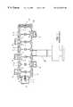
- FIG. 1depicts a side-coupled standing-wave linear accelerator.
- This type of acceleratorhas been widely used in medical and industrial applications because it offers very high shunt impedance and operational stability.
- most of these acceleratorsuse solely ⁇ /2 operational mode in the single section standing wave accelerator structure.
- the invention of the side coupled structurepermitted elimination of a bend magnet and use of an extremely short in-line accelerator in a 360° isocentric gantry for low energy radiation therapy machines.
- electrons 4which are generated in the cathode 2 of the electron gun 1 , are accelerated by DC voltage applied between the cathode 2 and the anode 7 and injected directly into the first cavity 3 .
- the applied voltage between the cathode 2 and anode 7is only 10 to 30 kev, the velocities of these injected electrons are much slower than the velocity of light. As a result, the trajectories of the injected electrons depend strongly on the accelerating microwave electric field within the first cavity 3 .
- the microwave power fed through the waveguide 25generates an accelerating microwave electric field within the accelerating cavities 8 .
- the microwave poweris transmitted through apertures 5 of the coupling cavities 6 where accelerating cavities and coupling cavities are magnetically coupled through the aperture 5 .
- these coupling aperturesare positioned away from the beam center where the electrons are accelerated. Due to the nature of these non-axisymmetric coupling apertures, the resultant accelerating electric field tends to offset from the beam centerline. These offsets may not be significant for the acceleration of the electrons, which have a velocity very close to the velocity of light, because the longitudinal momentum of high velocity electrons are much larger than the transverse momentum due to space charge affect and transverse accelerating fields. For the electrons injected initially into the first cavity 3 , the trajectories will depend on the accelerating field within its cavity where coupling apertures are off-centered. Axisymmetric cavities excited with non-axisymmetric apertures tend to generate a non-axisymmetric electric field.
- the electrons accelerated in the first cavitytend to have non-axisymmetric electron distributions for a standing wave linear accelerator which uses only off-center magnetic coupling.
- This non-axisymmetric electron beam distributiongenerates non-symmetric Bremsstrahlung x-rays at the target 9 where normally very thin, but heavy metal (high atomic number)—such as tungsten—is imbedded into a water-cooled copper heat sink 10 .
- Another problem with this structureis that about two-thirds of the injected electrons are not accelerated in the first cavity because they are excited sinusoidally at the microwave frequency. Some of the electrons, which are not accepted in the first cavity, are often decelerated back to the electron gun, called back-bombardment, and damage the cathode of the electron gun.
- the disadvantages associated with the prior artare overcome by a standing wave accelerator structure that has both inline coupling cavities and side coupling cavities combined into one structure. Additionally, the invention uses a prebunching (re-entrant) cavity, excited electrically or magnetically, through apertures between a first accelerating cavity and the prebunching cavity.
- FIG. 1depicts a cross-sectional view of a side coupled, standing wave linear accelerator of a the prior art
- FIG. 2depicts a cross-sectional view of a high gradient side coupled, standing wave linear accelerator of the present invention
- FIG. 3depicts an axisymmetric coupling aperture
- FIG. 4depicts an equivalent circuit representation of an axisymmetric coupling aperture
- FIG. 5depicts a non-axisymmetric coupling aperture
- FIG. 6depicts an equivalent circuit representation of a non-axisymmetric coupling aperture.
- the disadvantages associated with prior art side-coupled standing wave linear accelerator structurescan be eliminated by the structure shown in FIG. 2 .
- the excited electrons on the cathode 11(within electron gun 1 ) are accelerated by the voltage applied between the cathode 11 and an additional anode 12 .
- the electronsare injected first into a relatively small re-entrant cavity 13 , which is formed between an additional anode 12 and the original anode 14 .
- the diameter of the re-entrant cavity 13is about half the diameter of cavities 16 , 17 , 18 and 8 .
- the electron velocityis modulated slightly by the microwave field leaked through the apertures 15 axisymmetrically placed between first accelerating cavity and the re-entrant cavity 13 that is placed between the electron gun 1 and the first cavity 16 .
- This low level microwave power couplingcan be obtained through either electric or magnetic axisymmetric coupling apertures 15 .
- low level microwave powercan be fed to the re-entrant cavity 13 through a coaxial cable and coupling loop antenna.
- an appropriate gun voltageapproximately 10-15 kV
- drift distanceabout 16 mm
- modulating power levelabout 5 kW
- the first cavity 16is coupled with the accelerating cavity 18 through a disk-shaped coupling cavity 17 where microwave power is coupled electrically through electrical coupling apertures 20 and 21 .
- the advantage of using electrical couplingis that the coupling aperture can be axisymmetric as showing in FIG. 3 (FIG. 4 depicts an equivalent circuit representation of the aperture of FIG. 3) instead of a non-axisymmetric coupling aperture as shown in FIG. 5 (FIG. 6 depicts an equivalent circuit representation of the aperture of FIG. 5 ).
- FIG. 4depicts an equivalent circuit representation of the aperture of FIG. 3
- FIG. 6depicts an equivalent circuit representation of the aperture of FIG. 5 .
- the slower bunched electrons injected through the beam aperture 14are axisymmetrically accelerated with a high accelerating microwave electric field in the first cavity 16 .
- the accelerated electronswill maintain axisymmetric charge distribution while pre-acceleration is accomplished by axisymmetric accelerating field obtained by electrical aperture coupling between the first accelerating cavity and the second main accelerating cavity.
- the generated electronscan be prebunched within the tiny prebuncher (re-entrant) cavity before entering into the first accelerating cavity.
- the prebuncher cavitycan be axisymmetrically excited magnetically or electrically through very small apertures between the first accelerating cavity and the prebunching tiny cavity.
- the acceleratorutilizes different operational modes, such as ⁇ /2 and ⁇ mode, within a single section standing wave structure.
Landscapes
- Physics & Mathematics (AREA)
- Engineering & Computer Science (AREA)
- Plasma & Fusion (AREA)
- Spectroscopy & Molecular Physics (AREA)
- Particle Accelerators (AREA)
Abstract
Description
This patent application claims benefit of U.S. provisional patent application Ser. No. 60/097,162, filed Aug. 19, 1998, the disclosure of which is incorporated herein by reference.
FIG. 1 depicts a side-coupled standing-wave linear accelerator. This type of accelerator has been widely used in medical and industrial applications because it offers very high shunt impedance and operational stability. In order to increase shunt impedance per unit length, most of these accelerators use solely π/2 operational mode in the single section standing wave accelerator structure. For instance, the invention of the side coupled structure permitted elimination of a bend magnet and use of an extremely short in-line accelerator in a 360° isocentric gantry for low energy radiation therapy machines. In this short standing wave linear accelerator structure, electrons4 which are generated in thecathode 2 of theelectron gun 1, are accelerated by DC voltage applied between thecathode 2 and the anode7 and injected directly into the first cavity3.
Since the applied voltage between thecathode 2 and anode7 is only 10 to 30 kev, the velocities of these injected electrons are much slower than the velocity of light. As a result, the trajectories of the injected electrons depend strongly on the accelerating microwave electric field within the first cavity3. The microwave power fed through the waveguide25 generates an accelerating microwave electric field within the acceleratingcavities 8. The microwave power is transmitted throughapertures 5 of thecoupling cavities 6 where accelerating cavities and coupling cavities are magnetically coupled through theaperture 5.
In order to efficiently couple these cavities magnetically, these coupling apertures are positioned away from the beam center where the electrons are accelerated. Due to the nature of these non-axisymmetric coupling apertures, the resultant accelerating electric field tends to offset from the beam centerline. These offsets may not be significant for the acceleration of the electrons, which have a velocity very close to the velocity of light, because the longitudinal momentum of high velocity electrons are much larger than the transverse momentum due to space charge affect and transverse accelerating fields. For the electrons injected initially into the first cavity3, the trajectories will depend on the accelerating field within its cavity where coupling apertures are off-centered. Axisymmetric cavities excited with non-axisymmetric apertures tend to generate a non-axisymmetric electric field. As a result, the electrons accelerated in the first cavity tend to have non-axisymmetric electron distributions for a standing wave linear accelerator which uses only off-center magnetic coupling. This non-axisymmetric electron beam distribution generates non-symmetric Bremsstrahlung x-rays at thetarget 9 where normally very thin, but heavy metal (high atomic number)—such as tungsten—is imbedded into a water-cooledcopper heat sink 10.
Another problem with this structure is that about two-thirds of the injected electrons are not accelerated in the first cavity because they are excited sinusoidally at the microwave frequency. Some of the electrons, which are not accepted in the first cavity, are often decelerated back to the electron gun, called back-bombardment, and damage the cathode of the electron gun.
Therefore, there is a need in the art for a linear accelerator having improved electron acceleration characteristics for compact side-coupled standing wave accelerators.
The disadvantages associated with the prior art are overcome by a standing wave accelerator structure that has both inline coupling cavities and side coupling cavities combined into one structure. Additionally, the invention uses a prebunching (re-entrant) cavity, excited electrically or magnetically, through apertures between a first accelerating cavity and the prebunching cavity.
The teachings of the present invention can be readily understood by considering the following detailed description in conjunction with the accompanying drawings, in which:
FIG. 1 depicts a cross-sectional view of a side coupled, standing wave linear accelerator of a the prior art;
FIG. 2 depicts a cross-sectional view of a high gradient side coupled, standing wave linear accelerator of the present invention;
FIG. 3 depicts an axisymmetric coupling aperture;
FIG. 4 depicts an equivalent circuit representation of an axisymmetric coupling aperture;
FIG. 5 depicts a non-axisymmetric coupling aperture; and
FIG. 6 depicts an equivalent circuit representation of a non-axisymmetric coupling aperture.
To facilitate understanding, identical reference numerals have been used, where possible, to designate identical elements that are common to the figures.
The disadvantages associated with prior art side-coupled standing wave linear accelerator structures can be eliminated by the structure shown in FIG.2. The excited electrons on the cathode11 (within electron gun1) are accelerated by the voltage applied between the cathode11 and anadditional anode 12. The electrons are injected first into a relatively small re-entrant cavity13, which is formed between anadditional anode 12 and the original anode14. The diameter of the re-entrant cavity13 is about half the diameter ofcavities apertures 15 axisymmetrically placed between first accelerating cavity and the re-entrant cavity13 that is placed between theelectron gun 1 and thefirst cavity 16. This low level microwave power coupling can be obtained through either electric or magneticaxisymmetric coupling apertures 15. Alternatively, low level microwave power can be fed to the re-entrant cavity13 through a coaxial cable and coupling loop antenna. As a result, while the electron is traveling through the beam aperture14, electrons are prebunched and injected into thefirst cavity 16. By choosing an appropriate gun voltage (approximately 10-15 kV), drift distance (about 16 mm), and modulating power level (about 5 kW), almost all prebunched electrons are accepted into thefirst accelerator cavity 16.
Also, thefirst cavity 16 is coupled with the acceleratingcavity 18 through a disk-shaped coupling cavity 17 where microwave power is coupled electrically throughelectrical coupling apertures first cavity 16. While these pre-accelerated electrons are further bunched through drifting in thecavity 17 where no accelerating field existed, they are injected into a main acceleratingcavity 18 where electron energy may reach above 1Million Volts. At that time, the longitudinal momentum is high enough so that the electron will not be affected significantly by nonsymmetrical accelerating fields which the rest of the accelerator cavity has.
In this way the accelerator structure of the present invention offers the following characteristics:
1. The accelerated electrons will maintain axisymmetric charge distribution while pre-acceleration is accomplished by axisymmetric accelerating field obtained by electrical aperture coupling between the first accelerating cavity and the second main accelerating cavity.
2. Both electrical and magnetic couplings are mixed within one structure in order to utilize both advantages.
3. The generated electrons can be prebunched within the tiny prebuncher (re-entrant) cavity before entering into the first accelerating cavity. The prebuncher cavity can be axisymmetrically excited magnetically or electrically through very small apertures between the first accelerating cavity and the prebunching tiny cavity.
4. The accelerator utilizes different operational modes, such as π/2 and π mode, within a single section standing wave structure.
Although various embodiments which incorporate the teachings of the present invention have been shown and described in detail herein, those skilled in the art can readily devise many other varied embodiments that still incorporate these teachings. For instance, the invention can be readily utilized for longer high energy dual photon accelerators where low energy, high current beam must be transported through a longer accelerating structure. Another application is for the high gradient, higher energy RF gun where beam emittance and symmetry are very important.
Claims (8)
1. A linear accelerator comprising:
a cathode;
a re-entrant cavity; and
a plurality of accelerating cavities, where the re-entrant cavity is located between the cathode and the plurality of accelerating cavities.
2. The linear accelerator of claim1 wherein said re-entrant cavity has a diameter that is smaller than a diameter of said plurality of accelerating cavities.
3. The linear accelerator of claim1 wherein said re-entrant cavity is defined by a first anode and a second anode.
4. The linear accelerator of claim1 wherein said plurality of accelerating cavities comprises a first accelerating cavity, coupled to a said re-entrant cavity through an axisymmetric aperture.
5. The linear accelerator of claim4 wherein said axisymmetric aperture are either electric or magnetic coupling apertures.
6. The linear accelerator of claim1 wherein said plurality of accelerating cavities comprise a first acceleration cavity, a disk-shaped coupling cavity, and a plurality of accelerating cavities.
7. The linear accelerator of claim1 wherein electrons from the cathode are prebunched in the re-entrant cavity.
8. The linear accelerator of claim7 wherein the electrons are prebunched using either electric or magnetic coupling.
Priority Applications (1)
| Application Number | Priority Date | Filing Date | Title |
|---|---|---|---|
| US09/375,752US6316876B1 (en) | 1998-08-19 | 1999-08-18 | High gradient, compact, standing wave linear accelerator structure |
Applications Claiming Priority (2)
| Application Number | Priority Date | Filing Date | Title |
|---|---|---|---|
| US9716298P | 1998-08-19 | 1998-08-19 | |
| US09/375,752US6316876B1 (en) | 1998-08-19 | 1999-08-18 | High gradient, compact, standing wave linear accelerator structure |
Publications (1)
| Publication Number | Publication Date |
|---|---|
| US6316876B1true US6316876B1 (en) | 2001-11-13 |
Family
ID=26792762
Family Applications (1)
| Application Number | Title | Priority Date | Filing Date |
|---|---|---|---|
| US09/375,752Expired - LifetimeUS6316876B1 (en) | 1998-08-19 | 1999-08-18 | High gradient, compact, standing wave linear accelerator structure |
Country Status (1)
| Country | Link |
|---|---|
| US (1) | US6316876B1 (en) |
Cited By (56)
| Publication number | Priority date | Publication date | Assignee | Title |
|---|---|---|---|---|
| US6465957B1 (en)* | 2001-05-25 | 2002-10-15 | Siemens Medical Solutions Usa, Inc. | Standing wave linear accelerator with integral prebunching section |
| WO2004033613A3 (en)* | 2002-10-11 | 2004-07-08 | Scantech Holdings Llc | Standing-wave electron linear accelerator |
| WO2005076674A1 (en)* | 2004-02-01 | 2005-08-18 | Mian Yang Gao Xin Qu Twin Peak Technology Development Inc. | A phase switch and a standing wave linear accelerator with the phase switch |
| US20070120508A1 (en)* | 2005-11-27 | 2007-05-31 | Hanna Samy M | Particle accelerator and methods therefor |
| US7442940B2 (en) | 2006-05-05 | 2008-10-28 | Virgin Island Microsystems, Inc. | Focal plane array incorporating ultra-small resonant structures |
| US7470920B2 (en) | 2006-01-05 | 2008-12-30 | Virgin Islands Microsystems, Inc. | Resonant structure-based display |
| US7476907B2 (en) | 2006-05-05 | 2009-01-13 | Virgin Island Microsystems, Inc. | Plated multi-faceted reflector |
| US7492868B2 (en) | 2006-04-26 | 2009-02-17 | Virgin Islands Microsystems, Inc. | Source of x-rays |
| WO2007081391A3 (en)* | 2006-01-05 | 2009-04-16 | Virgin Islands Microsystems | Selectable frequency light emitter |
| US20090140177A1 (en)* | 2007-10-12 | 2009-06-04 | David Whittum | Charged particle accelerators, radiation sources, system, and methods |
| US7554083B2 (en) | 2006-05-05 | 2009-06-30 | Virgin Islands Microsystems, Inc. | Integration of electromagnetic detector on integrated chip |
| US7557647B2 (en) | 2006-05-05 | 2009-07-07 | Virgin Islands Microsystems, Inc. | Heterodyne receiver using resonant structures |
| US7558490B2 (en) | 2006-04-10 | 2009-07-07 | Virgin Islands Microsystems, Inc. | Resonant detector for optical signals |
| US7557365B2 (en) | 2005-09-30 | 2009-07-07 | Virgin Islands Microsystems, Inc. | Structures and methods for coupling energy from an electromagnetic wave |
| US7560716B2 (en) | 2006-09-22 | 2009-07-14 | Virgin Islands Microsystems, Inc. | Free electron oscillator |
| US7569836B2 (en) | 2006-05-05 | 2009-08-04 | Virgin Islands Microsystems, Inc. | Transmission of data between microchips using a particle beam |
| US7573045B2 (en) | 2006-05-15 | 2009-08-11 | Virgin Islands Microsystems, Inc. | Plasmon wave propagation devices and methods |
| US7579609B2 (en) | 2005-12-14 | 2009-08-25 | Virgin Islands Microsystems, Inc. | Coupling light of light emitting resonator to waveguide |
| US7583370B2 (en) | 2006-05-05 | 2009-09-01 | Virgin Islands Microsystems, Inc. | Resonant structures and methods for encoding signals into surface plasmons |
| US7586097B2 (en) | 2006-01-05 | 2009-09-08 | Virgin Islands Microsystems, Inc. | Switching micro-resonant structures using at least one director |
| US7586167B2 (en) | 2006-05-05 | 2009-09-08 | Virgin Islands Microsystems, Inc. | Detecting plasmons using a metallurgical junction |
| US7605835B2 (en) | 2006-02-28 | 2009-10-20 | Virgin Islands Microsystems, Inc. | Electro-photographic devices incorporating ultra-small resonant structures |
| US7626179B2 (en) | 2005-09-30 | 2009-12-01 | Virgin Island Microsystems, Inc. | Electron beam induced resonance |
| US7646991B2 (en) | 2006-04-26 | 2010-01-12 | Virgin Island Microsystems, Inc. | Selectable frequency EMR emitter |
| US7655934B2 (en) | 2006-06-28 | 2010-02-02 | Virgin Island Microsystems, Inc. | Data on light bulb |
| US7656094B2 (en) | 2006-05-05 | 2010-02-02 | Virgin Islands Microsystems, Inc. | Electron accelerator for ultra-small resonant structures |
| US7659513B2 (en) | 2006-12-20 | 2010-02-09 | Virgin Islands Microsystems, Inc. | Low terahertz source and detector |
| US7679067B2 (en) | 2006-05-26 | 2010-03-16 | Virgin Island Microsystems, Inc. | Receiver array using shared electron beam |
| US7688274B2 (en) | 2006-02-28 | 2010-03-30 | Virgin Islands Microsystems, Inc. | Integrated filter in antenna-based detector |
| US7710040B2 (en) | 2006-05-05 | 2010-05-04 | Virgin Islands Microsystems, Inc. | Single layer construction for ultra small devices |
| US7718977B2 (en) | 2006-05-05 | 2010-05-18 | Virgin Island Microsystems, Inc. | Stray charged particle removal device |
| US7723698B2 (en) | 2006-05-05 | 2010-05-25 | Virgin Islands Microsystems, Inc. | Top metal layer shield for ultra-small resonant structures |
| US7728702B2 (en) | 2006-05-05 | 2010-06-01 | Virgin Islands Microsystems, Inc. | Shielding of integrated circuit package with high-permeability magnetic material |
| US7728397B2 (en) | 2006-05-05 | 2010-06-01 | Virgin Islands Microsystems, Inc. | Coupled nano-resonating energy emitting structures |
| US7732786B2 (en) | 2006-05-05 | 2010-06-08 | Virgin Islands Microsystems, Inc. | Coupling energy in a plasmon wave to an electron beam |
| US7741934B2 (en) | 2006-05-05 | 2010-06-22 | Virgin Islands Microsystems, Inc. | Coupling a signal through a window |
| US7746532B2 (en) | 2006-05-05 | 2010-06-29 | Virgin Island Microsystems, Inc. | Electro-optical switching system and method |
| US7791053B2 (en) | 2007-10-10 | 2010-09-07 | Virgin Islands Microsystems, Inc. | Depressed anode with plasmon-enabled devices such as ultra-small resonant structures |
| US7791290B2 (en) | 2005-09-30 | 2010-09-07 | Virgin Islands Microsystems, Inc. | Ultra-small resonating charged particle beam modulator |
| US7876793B2 (en) | 2006-04-26 | 2011-01-25 | Virgin Islands Microsystems, Inc. | Micro free electron laser (FEL) |
| US7986113B2 (en) | 2006-05-05 | 2011-07-26 | Virgin Islands Microsystems, Inc. | Selectable frequency light emitter |
| US7990336B2 (en) | 2007-06-19 | 2011-08-02 | Virgin Islands Microsystems, Inc. | Microwave coupled excitation of solid state resonant arrays |
| CN101778527B (en)* | 2010-02-03 | 2012-05-09 | 中国科学技术大学 | Independent tuning microwave electron gun with external cathode |
| US8188431B2 (en) | 2006-05-05 | 2012-05-29 | Jonathan Gorrell | Integration of vacuum microelectronic device with integrated circuit |
| US20120200238A1 (en)* | 2009-08-21 | 2012-08-09 | Thales | Microwave Device for Accelerating Electrons |
| CN103260332A (en)* | 2013-05-29 | 2013-08-21 | 山东新华医疗器械股份有限公司 | Cross coupling standing wave accelerating tube |
| CN105072799A (en)* | 2015-09-22 | 2015-11-18 | 电子科技大学 | A dual-beam standing-wave electron linear accelerator of hybrid shaft-coupling and side-coupling |
| US20160014876A1 (en)* | 2014-07-09 | 2016-01-14 | The Board Of Trustees Of The Leland Stanford Junior University | Distributed Coupling and Multi-Frequency Microwave Accelerators |
| CN105555009A (en)* | 2016-01-19 | 2016-05-04 | 中国科学技术大学 | Energy switch for on-axis electrical coupling standing wave accelerating tube |
| US20160133428A1 (en)* | 2014-11-12 | 2016-05-12 | Schlumberger Technology Corporation | Radiation Generator With Frustoconical Electrode Configuration |
| US9380695B2 (en) | 2014-06-04 | 2016-06-28 | The Board Of Trustees Of The Leland Stanford Junior University | Traveling wave linear accelerator with RF power flow outside of accelerating cavities |
| US9655227B2 (en) | 2014-06-13 | 2017-05-16 | Jefferson Science Associates, Llc | Slot-coupled CW standing wave accelerating cavity |
| US9805904B2 (en) | 2014-11-12 | 2017-10-31 | Schlumberger Technology Corporation | Radiation generator with field shaping electrode |
| US20200187345A1 (en)* | 2018-12-11 | 2020-06-11 | Aet, Inc. | Compact standing-wave linear accelerator structure |
| GB2590457A (en)* | 2019-12-19 | 2021-06-30 | Elekta ltd | Radiotherapy device |
| US12285635B2 (en) | 2018-07-28 | 2025-04-29 | Varian Medical Systems, Inc. | Single-pass imaging and radiation treatment delivery via an extended rotation gantry |
Citations (3)
| Publication number | Priority date | Publication date | Assignee | Title |
|---|---|---|---|---|
| US4400650A (en)* | 1980-07-28 | 1983-08-23 | Varian Associates, Inc. | Accelerator side cavity coupling adjustment |
| US5039910A (en)* | 1987-05-22 | 1991-08-13 | Mitsubishi Denki Kabushiki Kaisha | Standing-wave accelerating structure with different diameter bores in bunching and regular cavity sections |
| EP0558296A1 (en)* | 1992-02-25 | 1993-09-01 | Varian Associates, Inc. | Linear accelerator with improved input cavity structure |
- 1999
- 1999-08-18USUS09/375,752patent/US6316876B1/ennot_activeExpired - Lifetime
Patent Citations (4)
| Publication number | Priority date | Publication date | Assignee | Title |
|---|---|---|---|---|
| US4400650A (en)* | 1980-07-28 | 1983-08-23 | Varian Associates, Inc. | Accelerator side cavity coupling adjustment |
| US5039910A (en)* | 1987-05-22 | 1991-08-13 | Mitsubishi Denki Kabushiki Kaisha | Standing-wave accelerating structure with different diameter bores in bunching and regular cavity sections |
| EP0558296A1 (en)* | 1992-02-25 | 1993-09-01 | Varian Associates, Inc. | Linear accelerator with improved input cavity structure |
| US5381072A (en)* | 1992-02-25 | 1995-01-10 | Varian Associates, Inc. | Linear accelerator with improved input cavity structure and including tapered drift tubes |
Cited By (75)
| Publication number | Priority date | Publication date | Assignee | Title |
|---|---|---|---|---|
| US6465957B1 (en)* | 2001-05-25 | 2002-10-15 | Siemens Medical Solutions Usa, Inc. | Standing wave linear accelerator with integral prebunching section |
| WO2004033613A3 (en)* | 2002-10-11 | 2004-07-08 | Scantech Holdings Llc | Standing-wave electron linear accelerator |
| WO2005076674A1 (en)* | 2004-02-01 | 2005-08-18 | Mian Yang Gao Xin Qu Twin Peak Technology Development Inc. | A phase switch and a standing wave linear accelerator with the phase switch |
| US20070096664A1 (en)* | 2004-02-01 | 2007-05-03 | Chongguo Yao | Phase switch and a standing wave linear accelerator with the phase switch |
| US7397206B2 (en) | 2004-02-01 | 2008-07-08 | Mian Yang Gao Xin Qu Twin Peak Technology Development Inc. | Phase switch and a standing wave linear accelerator with the phase switch |
| US7758739B2 (en) | 2004-08-13 | 2010-07-20 | Virgin Islands Microsystems, Inc. | Methods of producing structures for electron beam induced resonance using plating and/or etching |
| US7791291B2 (en) | 2005-09-30 | 2010-09-07 | Virgin Islands Microsystems, Inc. | Diamond field emission tip and a method of formation |
| US7626179B2 (en) | 2005-09-30 | 2009-12-01 | Virgin Island Microsystems, Inc. | Electron beam induced resonance |
| US7714513B2 (en) | 2005-09-30 | 2010-05-11 | Virgin Islands Microsystems, Inc. | Electron beam induced resonance |
| US7557365B2 (en) | 2005-09-30 | 2009-07-07 | Virgin Islands Microsystems, Inc. | Structures and methods for coupling energy from an electromagnetic wave |
| US7791290B2 (en) | 2005-09-30 | 2010-09-07 | Virgin Islands Microsystems, Inc. | Ultra-small resonating charged particle beam modulator |
| US7423381B2 (en) | 2005-11-27 | 2008-09-09 | Hanna Samy M | Particle accelerator and methods therefor |
| WO2007062195A3 (en)* | 2005-11-27 | 2009-05-07 | Samy M Hanna | Particle accelerator and methods therefor |
| US20090045746A1 (en)* | 2005-11-27 | 2009-02-19 | Hanna Samy M | Particle Accelerator and Methods Therefor |
| US20070120508A1 (en)* | 2005-11-27 | 2007-05-31 | Hanna Samy M | Particle accelerator and methods therefor |
| US7579609B2 (en) | 2005-12-14 | 2009-08-25 | Virgin Islands Microsystems, Inc. | Coupling light of light emitting resonator to waveguide |
| WO2007081391A3 (en)* | 2006-01-05 | 2009-04-16 | Virgin Islands Microsystems | Selectable frequency light emitter |
| US7586097B2 (en) | 2006-01-05 | 2009-09-08 | Virgin Islands Microsystems, Inc. | Switching micro-resonant structures using at least one director |
| US7470920B2 (en) | 2006-01-05 | 2008-12-30 | Virgin Islands Microsystems, Inc. | Resonant structure-based display |
| US8384042B2 (en) | 2006-01-05 | 2013-02-26 | Advanced Plasmonics, Inc. | Switching micro-resonant structures by modulating a beam of charged particles |
| US7619373B2 (en)* | 2006-01-05 | 2009-11-17 | Virgin Islands Microsystems, Inc. | Selectable frequency light emitter |
| US7688274B2 (en) | 2006-02-28 | 2010-03-30 | Virgin Islands Microsystems, Inc. | Integrated filter in antenna-based detector |
| US7605835B2 (en) | 2006-02-28 | 2009-10-20 | Virgin Islands Microsystems, Inc. | Electro-photographic devices incorporating ultra-small resonant structures |
| US7558490B2 (en) | 2006-04-10 | 2009-07-07 | Virgin Islands Microsystems, Inc. | Resonant detector for optical signals |
| US7646991B2 (en) | 2006-04-26 | 2010-01-12 | Virgin Island Microsystems, Inc. | Selectable frequency EMR emitter |
| US7876793B2 (en) | 2006-04-26 | 2011-01-25 | Virgin Islands Microsystems, Inc. | Micro free electron laser (FEL) |
| US7492868B2 (en) | 2006-04-26 | 2009-02-17 | Virgin Islands Microsystems, Inc. | Source of x-rays |
| US7710040B2 (en) | 2006-05-05 | 2010-05-04 | Virgin Islands Microsystems, Inc. | Single layer construction for ultra small devices |
| US7746532B2 (en) | 2006-05-05 | 2010-06-29 | Virgin Island Microsystems, Inc. | Electro-optical switching system and method |
| US7583370B2 (en) | 2006-05-05 | 2009-09-01 | Virgin Islands Microsystems, Inc. | Resonant structures and methods for encoding signals into surface plasmons |
| US7986113B2 (en) | 2006-05-05 | 2011-07-26 | Virgin Islands Microsystems, Inc. | Selectable frequency light emitter |
| US7656094B2 (en) | 2006-05-05 | 2010-02-02 | Virgin Islands Microsystems, Inc. | Electron accelerator for ultra-small resonant structures |
| US7476907B2 (en) | 2006-05-05 | 2009-01-13 | Virgin Island Microsystems, Inc. | Plated multi-faceted reflector |
| US8188431B2 (en) | 2006-05-05 | 2012-05-29 | Jonathan Gorrell | Integration of vacuum microelectronic device with integrated circuit |
| US7554083B2 (en) | 2006-05-05 | 2009-06-30 | Virgin Islands Microsystems, Inc. | Integration of electromagnetic detector on integrated chip |
| US7569836B2 (en) | 2006-05-05 | 2009-08-04 | Virgin Islands Microsystems, Inc. | Transmission of data between microchips using a particle beam |
| US7442940B2 (en) | 2006-05-05 | 2008-10-28 | Virgin Island Microsystems, Inc. | Focal plane array incorporating ultra-small resonant structures |
| US7718977B2 (en) | 2006-05-05 | 2010-05-18 | Virgin Island Microsystems, Inc. | Stray charged particle removal device |
| US7723698B2 (en) | 2006-05-05 | 2010-05-25 | Virgin Islands Microsystems, Inc. | Top metal layer shield for ultra-small resonant structures |
| US7728702B2 (en) | 2006-05-05 | 2010-06-01 | Virgin Islands Microsystems, Inc. | Shielding of integrated circuit package with high-permeability magnetic material |
| US7728397B2 (en) | 2006-05-05 | 2010-06-01 | Virgin Islands Microsystems, Inc. | Coupled nano-resonating energy emitting structures |
| US7732786B2 (en) | 2006-05-05 | 2010-06-08 | Virgin Islands Microsystems, Inc. | Coupling energy in a plasmon wave to an electron beam |
| US7741934B2 (en) | 2006-05-05 | 2010-06-22 | Virgin Islands Microsystems, Inc. | Coupling a signal through a window |
| US7586167B2 (en) | 2006-05-05 | 2009-09-08 | Virgin Islands Microsystems, Inc. | Detecting plasmons using a metallurgical junction |
| US7557647B2 (en) | 2006-05-05 | 2009-07-07 | Virgin Islands Microsystems, Inc. | Heterodyne receiver using resonant structures |
| US7573045B2 (en) | 2006-05-15 | 2009-08-11 | Virgin Islands Microsystems, Inc. | Plasmon wave propagation devices and methods |
| US7679067B2 (en) | 2006-05-26 | 2010-03-16 | Virgin Island Microsystems, Inc. | Receiver array using shared electron beam |
| US7655934B2 (en) | 2006-06-28 | 2010-02-02 | Virgin Island Microsystems, Inc. | Data on light bulb |
| US7560716B2 (en) | 2006-09-22 | 2009-07-14 | Virgin Islands Microsystems, Inc. | Free electron oscillator |
| US7659513B2 (en) | 2006-12-20 | 2010-02-09 | Virgin Islands Microsystems, Inc. | Low terahertz source and detector |
| US7990336B2 (en) | 2007-06-19 | 2011-08-02 | Virgin Islands Microsystems, Inc. | Microwave coupled excitation of solid state resonant arrays |
| US7791053B2 (en) | 2007-10-10 | 2010-09-07 | Virgin Islands Microsystems, Inc. | Depressed anode with plasmon-enabled devices such as ultra-small resonant structures |
| US8111025B2 (en) | 2007-10-12 | 2012-02-07 | Varian Medical Systems, Inc. | Charged particle accelerators, radiation sources, systems, and methods |
| US10314151B2 (en) | 2007-10-12 | 2019-06-04 | Varex Imaging Corporation | Charged particle accelerators, radiation sources, systems, and methods |
| US20090140177A1 (en)* | 2007-10-12 | 2009-06-04 | David Whittum | Charged particle accelerators, radiation sources, system, and methods |
| US9030134B2 (en) | 2007-10-12 | 2015-05-12 | Vanan Medical Systems, Inc. | Charged particle accelerators, radiation sources, systems, and methods |
| US8716958B2 (en)* | 2009-08-21 | 2014-05-06 | Thales | Microwave device for accelerating electrons |
| US20120200238A1 (en)* | 2009-08-21 | 2012-08-09 | Thales | Microwave Device for Accelerating Electrons |
| CN101778527B (en)* | 2010-02-03 | 2012-05-09 | 中国科学技术大学 | Independent tuning microwave electron gun with external cathode |
| CN103260332A (en)* | 2013-05-29 | 2013-08-21 | 山东新华医疗器械股份有限公司 | Cross coupling standing wave accelerating tube |
| US9380695B2 (en) | 2014-06-04 | 2016-06-28 | The Board Of Trustees Of The Leland Stanford Junior University | Traveling wave linear accelerator with RF power flow outside of accelerating cavities |
| US9655227B2 (en) | 2014-06-13 | 2017-05-16 | Jefferson Science Associates, Llc | Slot-coupled CW standing wave accelerating cavity |
| US9386682B2 (en)* | 2014-07-09 | 2016-07-05 | The Board Of Trustees Of The Leland Stanford Junior University | Distributed coupling and multi-frequency microwave accelerators |
| US20160014876A1 (en)* | 2014-07-09 | 2016-01-14 | The Board Of Trustees Of The Leland Stanford Junior University | Distributed Coupling and Multi-Frequency Microwave Accelerators |
| US20160133428A1 (en)* | 2014-11-12 | 2016-05-12 | Schlumberger Technology Corporation | Radiation Generator With Frustoconical Electrode Configuration |
| US9791592B2 (en)* | 2014-11-12 | 2017-10-17 | Schlumberger Technology Corporation | Radiation generator with frustoconical electrode configuration |
| US9805904B2 (en) | 2014-11-12 | 2017-10-31 | Schlumberger Technology Corporation | Radiation generator with field shaping electrode |
| CN105072799A (en)* | 2015-09-22 | 2015-11-18 | 电子科技大学 | A dual-beam standing-wave electron linear accelerator of hybrid shaft-coupling and side-coupling |
| CN105555009B (en)* | 2016-01-19 | 2018-08-03 | 中国科学技术大学 | A kind of axis powers on the energy switch of coupled standing wave accelerator tube |
| CN105555009A (en)* | 2016-01-19 | 2016-05-04 | 中国科学技术大学 | Energy switch for on-axis electrical coupling standing wave accelerating tube |
| US12285635B2 (en) | 2018-07-28 | 2025-04-29 | Varian Medical Systems, Inc. | Single-pass imaging and radiation treatment delivery via an extended rotation gantry |
| US20200187345A1 (en)* | 2018-12-11 | 2020-06-11 | Aet, Inc. | Compact standing-wave linear accelerator structure |
| US10750607B2 (en)* | 2018-12-11 | 2020-08-18 | Aet, Inc. | Compact standing-wave linear accelerator structure |
| GB2590457A (en)* | 2019-12-19 | 2021-06-30 | Elekta ltd | Radiotherapy device |
| GB2590457B (en)* | 2019-12-19 | 2023-10-11 | Elekta ltd | Radiotherapy device |
Similar Documents
| Publication | Publication Date | Title |
|---|---|---|
| US6316876B1 (en) | High gradient, compact, standing wave linear accelerator structure | |
| US5811943A (en) | Hollow-beam microwave linear accelerator | |
| US8786217B2 (en) | Interleaving multi-energy X-ray energy operation of a standing wave linear accelerator using electronic switches | |
| US20080100236A1 (en) | Multi-section particle accelerator with controlled beam current | |
| US8975816B2 (en) | Multiple output cavities in sheet beam klystron | |
| US6327339B1 (en) | Industrial x-ray/electron beam source using an electron accelerator | |
| US20080061718A1 (en) | Standing-wave electron linear accelerator apparatus and methods | |
| US4641103A (en) | Microwave electron gun | |
| US6559610B2 (en) | Continuous wave electron-beam accelerator and continuous wave electron-beam accelerating method thereof | |
| US5412283A (en) | Proton accelerator using a travelling wave with magnetic coupling | |
| US20250048529A1 (en) | Ceramic enhanced travelling wave accelerator structure | |
| JP3010169B1 (en) | High electric field small standing wave linear accelerator | |
| Lawson et al. | Design of a 10-MW, 91.4-GHz frequency-doubling gyroklystron for advanced accelerator applications | |
| US3443146A (en) | Conductive elements interconnecting adjacent members of the delay structure in a traveling wave tube | |
| US3274430A (en) | Biased-gap klystron | |
| US5659228A (en) | Charged particle accelerator | |
| CA1222563A (en) | Emitron: microwave diode | |
| US3249792A (en) | Traveling wave tube with fast wave interaction means | |
| Nepal et al. | Design study on standing-wave linear accelerator | |
| Fang et al. | An experimental test of a microwave inverse Cerenkov accelerator (MICA) | |
| RU2081474C1 (en) | Multibeam o-type device | |
| Nezhevenko et al. | High‐Power Millimeter‐and Centimeter‐Wave Magnicons for Particle Accelerator Application | |
| Muramatsu et al. | Status of 2.45 GHz compact National Institute of Radiological Sciences electron cyclotron resonance ion source | |
| Bastien et al. | Extremely high power klystrons for particle accelerators | |
| Simonov et al. | Principles for design of high power pulsed microwave devices and devices with low operating voltage for accelerators |
Legal Events
| Date | Code | Title | Description |
|---|---|---|---|
| STCF | Information on status: patent grant | Free format text:PATENTED CASE | |
| CC | Certificate of correction | ||
| FPAY | Fee payment | Year of fee payment:4 | |
| FPAY | Fee payment | Year of fee payment:8 | |
| FPAY | Fee payment | Year of fee payment:12 |