US6315732B1 - Imaging catheter and methods of use for ultrasound-guided ablation - Google Patents
Imaging catheter and methods of use for ultrasound-guided ablationDownload PDFInfo
- Publication number
- US6315732B1 US6315732B1US09/357,378US35737899AUS6315732B1US 6315732 B1US6315732 B1US 6315732B1US 35737899 AUS35737899 AUS 35737899AUS 6315732 B1US6315732 B1US 6315732B1
- Authority
- US
- United States
- Prior art keywords
- transducer
- catheter
- imaging
- distal end
- longitudinal axis
- Prior art date
- Legal status (The legal status is an assumption and is not a legal conclusion. Google has not performed a legal analysis and makes no representation as to the accuracy of the status listed.)
- Expired - Lifetime
Links
Images


Classifications
- A—HUMAN NECESSITIES
- A61—MEDICAL OR VETERINARY SCIENCE; HYGIENE
- A61B—DIAGNOSIS; SURGERY; IDENTIFICATION
- A61B8/00—Diagnosis using ultrasonic, sonic or infrasonic waves
- A61B8/12—Diagnosis using ultrasonic, sonic or infrasonic waves in body cavities or body tracts, e.g. by using catheters
- A—HUMAN NECESSITIES
- A61—MEDICAL OR VETERINARY SCIENCE; HYGIENE
- A61B—DIAGNOSIS; SURGERY; IDENTIFICATION
- A61B8/00—Diagnosis using ultrasonic, sonic or infrasonic waves
- A61B8/08—Clinical applications
- A61B8/0833—Clinical applications involving detecting or locating foreign bodies or organic structures
- A61B8/0841—Clinical applications involving detecting or locating foreign bodies or organic structures for locating instruments
- A—HUMAN NECESSITIES
- A61—MEDICAL OR VETERINARY SCIENCE; HYGIENE
- A61B—DIAGNOSIS; SURGERY; IDENTIFICATION
- A61B8/00—Diagnosis using ultrasonic, sonic or infrasonic waves
- A61B8/44—Constructional features of the ultrasonic, sonic or infrasonic diagnostic device
- A61B8/4444—Constructional features of the ultrasonic, sonic or infrasonic diagnostic device related to the probe
- A61B8/445—Details of catheter construction
- A—HUMAN NECESSITIES
- A61—MEDICAL OR VETERINARY SCIENCE; HYGIENE
- A61B—DIAGNOSIS; SURGERY; IDENTIFICATION
- A61B8/00—Diagnosis using ultrasonic, sonic or infrasonic waves
- A61B8/44—Constructional features of the ultrasonic, sonic or infrasonic diagnostic device
- A61B8/4444—Constructional features of the ultrasonic, sonic or infrasonic diagnostic device related to the probe
- A61B8/4461—Features of the scanning mechanism, e.g. for moving the transducer within the housing of the probe
Definitions
- the inventionrelates generally to the field of ultrasound imaging, and in particular, to the imaging of body lumens with ultrasound imaging catheters.
- ablationis used to treat cardiac rhythm disturbances.
- Such a therapymay be used, for example, to treat atrial fibrillation by forming long, thin lesions of different curvilinear shapes in heart tissue.
- a physiciansteers a catheter through a vein or artery into the interior region of the heart that is to be treated.
- An ablation element carried on the distal end of the catheteris positioned near the tissue that is to be ablated.
- the delivery of ablating energymust be closely governed to avoid incidence of tissue damage and coagulum formation.
- the ablation cathetersmust be precisely positioned adjacent to and preferably in contact with the tissue to be treated, to ensure the lesions are properly located.
- Mini-transesophageal echocardiography (mini-TEE) probesare available, however, these probes must be swallowed or inserted down the patient's throat. Such probes are poorly tolerated by patients unless they are fully anesthetized. Further, these probes can be rather large (i.e., 20 French in diameter), use complex transducer configurations and are costly enough to discourage their disposal after a single use.
- ultrasound imaging systemsand in particular ultrasound imaging catheters, would be particularly useful in helping physicians monitor the positioning of ablation catheters. It is desirable, therefore, to have an ultrasound imaging catheter small enough to enter narrow and tortuous regions of the patient's vascular system. It also is desirable if such imaging systems were easy to operate and cost efficient to encourage their disposal after use.
- the present inventionprovides ultrasound imaging catheters, systems and methods for their use. Catheters and systems of the present invention will be particularly useful to monitor the positioning of ablation catheters. Catheters and systems of the present invention provide a relatively simple and inexpensive apparatus compared to alternative monitoring techniques, such as mini-TEE probes.
- the present inventionprovides an imaging catheter comprising a catheter body having a distal end, a proximal end and a longitudinal axis.
- a transduceris rotatably coupled to the catheter body distal end.
- the transducerhas an axis of rotation that is different from the catheter body longitudinal axis.
- the transducer axis of rotationis generally perpendicular to the longitudinal axis. In this manner, the transducer rotates to produce images in an imaging plane that is generally parallel to the longitudinal axis.
- Such a configurationprovides an exemplary side-looking imaging catheter.
- the catheter bodyhas a diameter that is less than about 16 French. Catheters of such dimensions are sufficiently small enough to enter tortuous regions of a patient's vasculature.
- the transducercomprises PZT.
- the transduceralso may comprise piezoplastics, piezocomposites, piezoceramics (e.g. PZT) and the like.
- the transduceris rotatably coupled to the distal end to permit 360 degree rotation of the transducer about the transducer rotational axis relative to the distal end. In such an arrangement, the transducer is rotated to produce ultrasound images throughout an imaging plane without the need to rotate the catheter body. In another particular aspect, the transducer is rotatably coupled to the distal end to permit up to about 180 degree rotation of the transducer about the rotational axis relative to the distal end.
- the transducerdefines a face that is generally elliptical in shape, although other transducer shapes are possible within the scope of the present invention.
- the facehas a major axis length that is greater than a diameter of the catheter body.
- the transducer face major axispreferably is positioned generally parallel to the catheter body longitudinal axis. The transducer can be rotated up to about 180 degrees of rotation using a wiper-like or teeter-totter type of rotational movement.
- the transducercomprises an annular array of transducer elements.
- the annular arraydefines a face that is generally elliptical in shape.
- the annular arraydefines a face that is generally circular in shape.
- the facemay be generally flat or have a spherical or other curvature.
- Exemplary annular arrays for use in the present inventionare further described in U.S. patent application Ser. No. 09/017,581, entitled “Annular Array Ultrasound Catheter,” filed Feb. 3, 1998, and assigned to the assignee of the present invention, the complete disclosure of which is incorporated herein by reference.
- the imaging catheterfurther includes a drive cable and a gear mechanism disposed within a working lumen of the catheter body.
- the drive cableis coupled to the transducer and to the gear mechanism.
- the drive cable and gear mechanismare adapted to rotate the transducer. In this manner, the drive cable and gear mechanism rotate the transducer, thereby eliminating the need to rotate the catheter body.
- the imaging catheterfurther includes a housing rotatably coupled to the distal end.
- the transduceris mounted within the housing. In such an embodiment, the transducer is rotated relative to the distal end by rotating the housing.
- the imaging cathetercomprises a housing operably attached to the distal end with the transducer being rotatably coupled to the housing.
- an imaging cathetercomprising a catheter body as previously described.
- the catheterfurther includes a plurality of transducer elements configured in an annular array.
- the annular arrayis rotatably coupled to the catheter body distal end, and has an axis of rotation that is at a non-zero angle relative to the catheter body longitudinal axis.
- the annular array axis of rotationis generally perpendicular to the longitudinal axis.
- an imaging catheterin still another embodiment, includes a catheter body having a distal end, a proximal end and a longitudinal axis.
- a transduceris rotatably coupled to the distal end to permit up to about 180 degrees of rotation about an axis of rotation that is not coaxial with the longitudinal axis. More preferably, the transducer axis of rotation is generally perpendicular to the catheter body longitudinal axis.
- the transducerdefines a face that is generally parallel to the longitudinal axis during a period of non-rotation.
- the transduceris adapted to rotate so that the face creates an angle with the longitudinal axis that is between about +90° and about ⁇ 90°.
- the present inventionfurther provides imaging catheter systems.
- the systemincludes a controller operably attached to the imaging catheter.
- the controlleroperates to display ultrasound images from signals received from the transducer and provides power to the imaging catheter.
- Such a systemis particularly useful for the monitoring of accurate positioning of an ablation catheter prior to and/or during ablation.
- the inventionfurther provides exemplary methods of imaging a body lumen.
- One particular methodincludes the steps of providing an imaging catheter comprising a catheter body and a transducer coupled to the catheter body distal end.
- the methodincludes inserting the imaging catheter into a patient and positioning the transducer at a desired location within the patient.
- the transduceris rotated about an axis of rotation that is at a non-zero angle relative to the longitudinal axis.
- the methodincludes energizing the transducer, capturing a plurality of reflected signals, and producing an image of at least a portion of the desired location based on the reflected signals.
- the transduceris positioned at a desired location within a patient's heart. In this manner, the transducer can be positioned to monitor the positioning of an ablation catheter within a patient, such as within a patient's heart.
- the catheter bodyhas a diameter that is less than about 16 French.
- a plurality of transducers configured in an annular arrayare provided. The annular array is rotatably coupled to the distal end and has an axis of rotation that is at an angle to the longitudinal axis.
- the transduceris energized to project a plurality of ultrasound signals into an imaging plane.
- the imaging planeis generally parallel to the longitudinal axis.
- the energizing and rotating stepsare coordinated to project a plurality of ultrasound signals into a sector or portion of the imaging plane.
- the energizing and rotating stepsare coordinated to project a plurality of ultrasound signals into a 360° sector of an imaging plane.
- an image of a portion of the imaging planeis produced.
- the transduceris rotated through an angular displacement that is less than about 180°.
- the transducerdefines a face that is generally parallel to the longitudinal axis during a period of non-rotation.
- the rotating stepincludes rotating the transducer so that the face creates an angle with the longitudinal axis that is between about +90° and about ⁇ 90°.
- the methodincludes the step of providing an imaging catheter ostensibly as previously described with a transducer fixedly attached to the distal end.
- the methodincludes inserting the imaging catheter into a patient, positioning the transducer at a desired location within the patient, and energizing the transducer to project a plurality of ultrasound signals into a first sector of the desired location.
- the methodincludes capturing a plurality of reflected signals, producing an image of at least a portion of the first sector using the reflected signals and axially translating the transducer within the patient to a second sector of the desired location.
- the methodincludes repeating the energizing, capturing and producing steps for a second sector. More preferably, the transducer is axially translated a plurality of times to produce a plurality of images from a plurality of sectors of the desired location. In one aspect, a three-dimensional image is produced by combining the images of the first and second sectors.
- the transduceris axially translated a specified distance by axially translating the proximal end the specified distance. In this manner, axial translation of the transducer can be controlled by axially translating the catheter proximal end maintained outside the patient's body.
- the energizing stepprojects a plurality of ultrasound signals into an imaging plane whereby the imaging plane is generally parallel to the longitudinal axis.
- the providing stepfurther includes providing a drive cable and a gear mechanism.
- the drive cableis coupled to the transducer and to the gear mechanism.
- the drive cable and gear mechanismare adapted to axially translate the transducer.
- an imaging catheterin another exemplary method of the present invention, is provided as previously described.
- the catheterincludes a housing proximal end that is coupled to a drive cable.
- the imaging catheteris inserted into a patient and the transducer is rotated by rotating the drive cable.
- the transduceris energized to project a first plurality of ultrasound signals into a first image plane.
- the methodincludes capturing a first plurality of reflected signals and producing a first image of at least a portion of the first image plane.
- the transduceris positioned at a desired location within the patient and the transducer is rotated relative to the distal end and to the drive cable.
- the methodincludes energizing the transducer to project a second plurality of ultrasound signals into a second plane, capturing a second plurality of reflected signals, and producing a second image of at least a portion of the second image plane.
- the transducerproduces images from two different image planes to help locate the desired location within the patient and to image the desired location.
- the first image planeis generally perpendicular to the housing longitudinal axis and the second image plane is generally parallel to the housing longitudinal axis. In another aspect, images are produced of the first image plane until the transducer is positioned at the desired location within the patient.
- the same transducerprojects signals into the first and second image planes. In a related aspect, the same transducer captures both the first and second plurality of ultrasound signals from the first and second image planes.
- an imaging catheter as previously describedis provided and inserted into a patient.
- the methodincludes the steps of rotating the transducer relative to the distal end and relative to the drive cable, energizing the transducer to project a plurality of ultrasound signals from the transducer, and rotating the drive cable to rotate the transducer.
- the steps of rotating the transducer, energizing the transducer and rotating the drive cableoccur simultaneously.
- the transducerprojects a plurality of ultrasound signals into a three dimensional imaging region.
- the methodincludes capturing a plurality of reflected signals from the imaging region and producing a three-dimensional image of at least a portion of the imaging region. In this manner, the present invention provides imaging catheters and methods of imaging capable of producing three dimensional images.
- the transducer rotating steprotates the transducer through an angular displacement that is less than about 180 degrees.
- the drive cable rotating steprotates the drive cable 360 degrees to rotate the transducer 360 degrees.
- the imaging regionhas a generally conical or hour-glass shape.
- the imaging regionis generally cylindrical or spherical in shape.
- the transducer rotating steprotates the transducer at a first angular rate of rotation and the drive cable rotating step rotates the drive cable, and hence the transducer, at a second angular rate of rotation.
- the first angular rate of rotationis faster than the second angular rate of rotation.
- the first angular rate of rotationis slower than the second angular rate of rotation.
- the transducer rotating steprotates the transducer about an axis that is generally perpendicular to the longitudinal axis.
- the drive cable rotating steprotates the transducer about the longitudinal axis. In this manner, the transducer can image in more than one plane, and preferably in a three-dimensional imaging region.
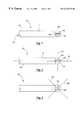
- FIG. 1provides an overall side view of an imaging catheter according to the present invention
- FIG. 2provides an overall top view of the imaging catheter depicted in FIG. 1;
- FIG. 3provides an overall top view of an imaging catheter of the present invention showing the transducer element rotational axis positioned at an angle with respect to the longitudinal axis;
- FIG. 4depicts an imaging plane for the catheter depicted in FIG. 1;
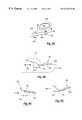
- FIGS. 5A-5Cdepict an alternative embodiment of an imaging catheter according to the present invention which provides up to about 180 degrees of transducer rotation;
- FIGS. 6A-6Cdepict top and side views of annular arrays for use with the present invention.
- FIGS. 7A-7Cdepict a housing and transducer to be rotatably coupled to the catheter body
- FIG. 8Adepicts a drive cable and gear mechanism for rotating a transducer
- FIGS. 8B-8Ddepict side views of a mechanism for rotating a transducer less than 360 degrees according to the present invention.
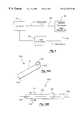
- FIG. 9depicts a schematic of an imaging catheter system according to the present invention.
- FIGS. 10A-10Bdepict an alternative embodiment of an imaging catheter according to the present invention.
- FIGS. 11A-11Bdepict still another embodiment of an imaging catheter according to the present invention.
- FIGS. 11C-11Ddepict three-dimensional imaging methods according to the present invention.
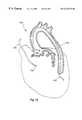
- FIG. 12depicts imaging and ablation catheters positioned inside a patient heart.
- FIGS. 1 and 2depict an imaging catheter 10 having a catheter body 11 .
- Catheter body 11has a distal end 12 , a proximal end 14 , and a longitudinal axis 16 .
- a lumen 18is provided within catheter body 11 and transducer 20 is rotatably coupled to distal end 12 .
- Arrows 22depict the rotation of transducer 20 with respect to distal end 12 . While arrows 22 in FIG. 1 depict a counter-clockwise rotation, a clockwise rotation also may be used.
- Transducer 20is rotatably coupled to catheter body 11 in a variety of manners. In one embodiment, transducer 20 is connected to distal end 12 using two rotatable attachment points 26 as shown in FIG. 2 . Other attachment methods are within the scope of the present invention, some of which are discussed further in conjunction with FIG. 7 .
- transducer 20rotates about an axis of rotation 24 that is not coaxial with the catheter body longitudinal axis 16 .
- transducer 20has axis of rotation 24 that is generally perpendicular to longitudinal axis 16 .
- the image planeis the plane into which transducer 20 propagates ultrasound signals during operation, and from which transducer 20 receives signals reflected from tissue and the like.
- transducer 20has axis of rotation 24 that is out of alignment with longitudinal axis 16 , but not perpendicular to axis 16 .
- Such an embodimentwill produce an image plane 28 that is at an angle with longitudinal axis 16 .
- transducer 20may be rotatably coupled to distal end 12 above a cavity 13 .
- cavity 13is filled with saline, or other coupling media.
- cavity 13is at least partially filled with a material having a high absorbency to ultrasound signals. In this manner, ultrasound signals are propagated from transducer 20 in a direction generally opposite cavity 13 .
- Transducer 20may, but need not comprise a rectangular transducer element as depicted in FIG. 2 .
- FIG. 3depicts transducer 20 as an elliptical or oval-shaped transducer element. Other shapes and configurations of transducer element 20 also are anticipated within the scope of the present invention.
- transducer 20may comprise a plurality of transducer elements, such as in the configuration described in conjunction with FIG. 6 .
- Transducer 20also may have a sound-attenuating backing material layer (not shown) operably attached to a transducer surface, and one or more matching layers (not shown) operably attached to an opposing transducer surface.
- the matching layer(s)-transducer-backing material layerrotate together as a unit.
- transducer 20As depicted in FIG. 4, the rotation of transducer element 20 (shown by arrows 22 ) results in transducer 20 being capable of producing images in image plane 28 .
- transducer 20is rotated 360 degrees and energized to propagate ultrasound signals into image plane 28 .
- Rotation of transducer 20 for 360 degreesmay comprise continuous 360 degree rotation in one direction, or rotation in one direction (e.g., clockwise) for about 360 degrees followed by rotation in the other direction (e.g., counterclockwise) for about 360 degrees.
- FIG. 8 AOne mechanism for providing such rotation is depicted in FIG. 8 A. While, the side view shown in FIG. 4 depicts a counterclockwise rotation of transducer 20 , a clockwise rotation also may be used.
- Transducer 20can be energized to propagate ultrasound signals into about a 360° image plane 28 . A portion of the ultrasound signals may be reflected or blocked by the catheter body. Hence not all signals will propagate into the patient's surrounding tissue. Alternatively, transducer 20 may be energized intermittently to propagate signals into a desired sector or region of image plane 28 . FIG. 4 depicts transducer 20 propagating ultrasound signals into a sector 30 of image plane 28 .
- transducer element 20can be rotated and energized in a coordinated fashion to propagate ultrasound signals only into sector 30 . Signals are reflected by a patient's tissues, fluids and the like, and the reflected signals are received by transducer 20 .
- one transducer 20is used to transmit ultrasound signals and a second transducer 20 is used to receive reflected signals. The reflected signals can be used to produce an image of sector 30 .
- transducer 20can propagate ultrasound signals into a larger angular region of image plane 28 or into the entire image plane 28 .
- FIGS. 5A-5Cdepict an alternative embodiment of the present invention.
- FIGS. 5A-Cdepict transducer element 20 rotatably coupled to catheter body 11 in a manner which provides less than 360° rotation of transducer 20 .
- One mechanism for providing such rotationis depicted in FIGS. 8B-8D.
- Such an arrangementis particularly useful for allowing an aperture of transducer 20 to exceed the diameter 34 of catheter body 1 .
- FIG. 5Adepicts transducer 20 having a span 32 that is greater than an inner diameter 34 of catheter body 11 .
- Span 32depends on the shape of transducer 20 .
- span 32is the diameter of a circular-shaped transducer 20 , is the major axis of an elliptical or oval transducer 20 , and is the longest side of a rectangular-shaped transducer 20 .
- transducer element 20is not rotated in a 360° fashion, but instead is rotated as indicated by arrows 22 in an up and down, wiper-like or teeter-totter type fashion as best shown in FIGS. 5 B and SC.
- a first face 36 of transducer 20preferably is generally parallel to axis 16 .
- face 36is rotated to produce an angle 38 with respect to axis 16 that varies between about +90° and about ⁇ 90°.
- Transducer 20rotates about rotating attachment points 26 to produce the rotational movement depicted by arrows 22 .
- Catheter body diameter 34preferably is less than about 16 French to permit its introduction into narrow, tortuous vasculatures.
- FIGS. 6A-6Cdepict alternative configurations of transducers for use in the present invention. While annular arrays are depicted, it will be appreciated by those skilled in the art that other arrays, including two-dimensional arrays and linear arrays, may be used within the scope of the present invention.
- FIG. 6Adepicts an annular array 50 comprising a plurality of transducer elements 54 .
- An annular arrayis defined as two or more generally concentric transducer elements surrounding a central point or axis.
- Annular arrays of the present inventionare configured so that the transducer elements of the array propagate ultrasound signals in the same general direction. Annular arrays of the present invention further preferably have a central element to avoid a central blind spot in the array.
- array 50has a major axis 52 that is longer than inner diameter 34 of catheter body 11 .
- insulating materials or kerfsare provided between transducer elements 54 of array 50 to reduce or eliminate cross-talk between adjoining transducer elements 54 .
- face 56within the scope of the present invention, also may have a different curvature than shown in FIG. 6 .
- face 56may have an elliptical or other focused curvature.
- transducer 20may be similarly shaped.
- FIG. 7A-7Cone manner of rotatably attaching transducer array 50 or transducer 20 to catheter body 11 according to the present invention will be described.
- array 50is fixedly attached to a housing 58 having rotating attachment points 60 .
- Rotating attachment points 60then are rotatably attached to distal end 12 to allow housing 58 and array 50 to rotate about attachment points 60 .
- attachment points 60are depicted in the approximate center of housing 58 or array 50 , attachment points 60 also may be located off center.
- FIG. 7Adepicts transducer array 50 partially disposed within housing 58 as indicated by dashed lines.
- FIG. 7Bdepicts array 50 operably attached to a surface of housing 58 .
- array 50may be fully disposed within a hole (not shown) within housing 58 .
- FIG. 7Cdepicts a cross-sectional view of housing 58 and array 50 depicted in FIG. 7 B.
- FIG. 7Cdepicts rotating attachment point 60 as an axle or a rod extending through housing 58 (not cross-hatched for convenience of illustration).
- the ends of attachment points 60are rotatably attached to distal end 12 to allow housing 58 /array 50 to rotate about attachment points 60 .
- an end 61 of attachment point 60can be inserted into holes, slots, grooves and the like, in distal end 12 of catheter body 11 to permit rotation.
- the configuration depicted in FIGS. 7A-7Cmay be used for rotation of array 50 (or transducer 20 ) 360 degrees (as in FIG. 4) or less than 360 degrees (as in FIGS. 5 A-C).
- FIG. 8Adepicts an embodiment for rotating transducer array 50 about an axis that is not coaxial with longitudinal axis 16 .
- attachment point 60is rotatably coupled to housing 58 and a gear mechanism 62 is operably attached thereto.
- a drive cable 64extends around gear mechanism 62 .
- Arrows 66indicate rotational movement of drive cable 64 . Movement of drive cable 64 causes gear mechanism 62 to rotate which, in turn, causes the rotation of transducer array 50 . While arrows 66 indicate a clockwise rotational movement in FIG. 8A, it will be appreciated that a counter-clockwise rotational movement also is within the scope of the present invention for both transducer 20 and array 50 .
- FIGS. 8B-8Ddepict a mechanism for rotating transducer array 50 or transducer 20 in a teeter-totter or wiper-like fashion in accordance with the present invention.
- Transducer array 50is depicted in housing 58 coupled to distal end 12 of catheter 10 .
- Attachment points 26provide a position about which housing 58 rotates as previously described.
- a translation mechanism 70is provided near distal end 12 to provide the teeter-totter motion of housing 58 .
- Mechanism 70comprises a support member 72 and a translation block 74 . Axial movement of block 74 , as shown by arrow 76 , causes one end of support member 72 to slide up or down block 74 .
- a spring or other tension member(not shown) is coupled to support member 72 to bias support member 72 into block 74 , thereby facilitating the sliding motion thereof as block 74 is axially translated.
- Support member 72further is coupled to housing 58 , and has sufficient stiffness to encourage rotation of housing 58 about points 26 as block 74 is translated.
- FIG. 8Cdepicts the translation of block 74 towards distal end 12 , causing array 50 to rotate into a forward looking position.
- FIG. 8Ddepicts the translation of block 74 away from distal end 12 , causing array 50 to rotate into a rearward looking position.
- block 74may be coupled to a small motor (not shown) in distal end 12 to provide the axial motion indicated by arrow 76 .
- Block 74further may be coupled to pair of orthogonal gears which translate a rotational motion, such as the rotation of a drive cable (not shown), into an axial motion of block 74 . It will be appreciated by those skilled in the art that other methods of axially translating block 74 also may be used within the scope of the present invention.
- FIG. 9depicts a controller 150 operably attached to a gear mechanism 156 and a transmission line 152 .
- Transmission line 152is operably attached to catheter 154 as further described below.
- Catheter 154is essentially the same as catheter 10 as previously described, including transducer 20 and a gear mechanism located at the catheter distal end, such as gear mechanism 62 described in conjunction with FIG. 8 .
- Catheter 154is operably attached to gear mechanism 156 using drive cable 64 .
- Drive cable 64is operably attached to gear mechanism 62 in distal end 12 of catheter 10 as depicted, for example, in FIG. 8 .
- Drive cable 64is operably connected to gear mechanism 156 which provides the rotational movement of drive cable 64 as indicated by arrows 66 in FIG. 8 .
- Single transducer catheterstypically involve fixedly attaching a transducer to a distal end of a drive cable, and rotating the drive cable to rotate the transducer. Such an arrangement results in the transducer having an axis of rotation that is coaxial to the catheter body longitudinal axis.
- gear mechanism 156is used to translate that typical rotational movement of a drive cable into a rotational movement of the transducer. It will be appreciated by those skilled in the art that gear mechanism 156 may comprise, for example, a pair of orthogonal gears to transfer rotational movement from one direction to another.
- Transmission line 152preferably extends from controller 150 , through catheter lumen 18 , and is adapted to be in electrical communication with transducer 20 .
- lumen 18is contained within drive cable 64 .
- transmission line 152may be operably attached to transducer 20 or transducer array 50 .
- transducer 20 or array 50is depicted being rotated 360 degrees.
- Transmission line 152 in one such embodimentis in communication with transducer 20 using slip rings (not shown), inductive coupling, flexible leads for embodiments having non-continuous 360 degree rotation, or the like.
- Controller 150includes electronics to provide power to imaging catheter 10 . Controller 150 further includes image producing software and the like for displaying ultrasound images of desired regions within the patient's anatomy.
- an imaging catheter 100having a catheter body 101 with a distal end 102 and a proximal end 104 .
- a transducer 110 or an array of transducer elementsare operably attached to distal end 102 of catheter body 101 .
- Gear mechanism 156is configured to provide a piston-like or forward and back motion of catheter 100 as depicted in FIG. 10 B. The motion, as indicated by arrows 112 , is generally parallel to the longitudinal axis 106 of catheter body 101 .
- Transmission lines and drive cablesare disposed within a lumen 108 of catheter body to provide the piston-like motion.
- proximal end 104is coupled to a drive cable, and the transmission lines are disposed within a lumen within the drive cable.
- Gear mechanism 156(see FIG. 9 ), located outside the patient's body, is adapted to provide the piston-like movement shown by arrows 112 .
- proximal end 104may be connected to gear mechanism 156 , to provide movement shown by arrows 112 .
- the extent of movementis controlled by controller 150 , which operates to control gear mechanism 156 .
- a physicianmay manually manipulate catheter 100 to produce axial movement of transducer 110 in the manner shown by arrows 112 .
- a method of using catheter 100includes inserting catheter 100 into a patient and positioning transducer 110 at a desired location within the patient.
- Transducer 110is energized to project a plurality of ultrasound signals into a first sector of the desired location.
- a plurality of reflected signalsare captured, and an image of at least a portion of the desired location is produced using the reflected signals.
- Transducer 110is axially translated to a second sector of the desired location to produce an image of the second sector in the same manner.
- axial translation of transducer 110can occur by a gear mechanism which provides a forward and back, piston-like movement. Alternatively, the physician can manually manipulate the catheter in an axial manner.
- This embodimentwill be particularly useful for producing three-dimensional images by combining the motion shown by arrows 112 , with rotation of catheter 100 about longitudinal axis 106 .
- rotation of catheter 100 while projecting ultrasound signals from transducer 110results in an image plane that is generally perpendicular to longitudinal axis 106 .
- transducer 110By simultaneously translating transducer 110 axially, such as shown by arrows 112 , a three dimensional region is imaged.
- FIGS. 11A-11Bdepict an imaging catheter 200 according to an alternative embodiment of the present invention.
- Catheter 200has a housing 210 .
- Housing 210has a distal end 212 , a proximal end 214 and a longitudinal axis 216 .
- a transducer 220is rotatably attached to distal end 212 as described in conjunction with earlier Figures.
- Proximal end 214is operably attached to a housing drive cable 222 .
- Housing drive cable 222may comprise, for example, stainless steel counterwound drive cables. Exemplary drive cables are described in U.S. patent application Ser. No. 09/017,578, entitled “Integrated Coaxial Transmission Line and Flexible Drive Cable,” the complete disclosure of which is incorporated herein by reference.
- Catheter 200may be disposed within a sheath (not shown), such as a polyethylene sheath.
- housing drive cable 222has a first lumen 224 and a second lumen 228 as depicted in FIG. 11 B.
- First lumen 224contains a transducer drive cable 226 , similar to drive cable 64 described in conjunction with FIG. 8 .
- Transducer drive cable 226operates to rotate transducer 220 relative to housing 210 as previously described and as shown by arrows 218 .
- Second lumen 228contains one or more transmission lines 230 , to permit the transmission/receipt of signals to/from transducer 220 .
- Housing drive cable 222connects to proximal end 214 and rotates housing 210 as shown by arrows 240 so that housing 210 has an axis of rotation that is generally parallel to axis 216 . It will be appreciated by those skilled in the art that arrows 218 and 240 can be used to indicate either clockwise or counterclockwise rotations.
- Catheter 200is inserted into a patient and maneuvered to position transducer 220 at a desired location within the patient.
- housing drive cable 222is rotated, which rotates housing 210 and transducer 220 .
- Transducer 220is energized to transmit ultrasound signals into an image plane, preferably a 360 degree image plane, that is generally perpendicular to axis 216 .
- image planepreferably a 360 degree image plane, that is generally perpendicular to axis 216 .
- transducer 220is maintained generally stationary with respect to housing 210 . Reflected signals are captured and transmitted to a controller, such as controller 150 described in conjunction with FIG. 9 .
- the reflected signalsare used to produce an image, which the operator or controller 150 can analyze to help determine the location of transducer 220 within the patient, for example by identifying known anatomical landmarks. This imaging mode can continue until transducer 220 reaches the desired location within the patient.
- transducer 220is positioned at the desired location, rotation of housing 210 ceases, and transducer 220 is rotated relative to housing 210 as described in conjunction with earlier Figures.
- transducer drive cables 226may be used to rotate transducer 220 .
- transducer 220produces images in a second image plane.
- the second image planemay be generally parallel to axis 216 (see FIG. 2) or at an angle relative to axis 216 (see FIG. 3 ).
- transducer 220is adapted to produce images in at least two different image planes.
- transducer 220is adapted to rotate about an axis of rotation 232 that is at an angle relative to longitudinal axis 216 .
- axis 232is depicted in FIG. 11C as being generally perpendicular to axis 216 .
- transducer 220is depicted as a single rectangular transducer, transducer 220 may have a wide range of shapes and may comprise more than one transducer element within the scope of the present invention. Absent rotation of drive cable 222 , transducer 220 projects ultrasound signals into, and receives signals from, a single imaging plane such as plane 250 A.
- plane 250 Ais not a full 360 degree imaging plane, and is generated, for example, by an angular rotation of transducer 220 about axis 232 that is less than 180 degrees.
- plane 250 Ais imaged by a wiper-like or teeter-totter rotation of transducer 220 .
- rotation of transducer 220 through an angular displacement from +90 degrees to ⁇ 90 degrees, or through 360 degrees,would produce a larger image plane 250 A.
- drive cable 222 rotationresults in transducer 220 rotation about longitudinal axis 216 .
- drive cable 222 rotationis a continuous 360 degree rotation.
- the imaging plane for transducer 220By simultaneously rotating transducer 220 relative to distal end 212 , energizing transducer 220 , and rotating drive cable 222 , the imaging plane for transducer 220 also rotates. As a result, a plurality of imaging planes 250 A- 250 D are imaged by transducer 220 . In other words, rotation of transducer 220 relative to distal end images a single plane, such as plane 250 A. Rotation of drive cable 222 results in different planes, such as planes 250 B-D, being imaged. In this manner, a three-dimensional region is imaged. Controller 150 (FIG. 9) then produces a three-dimensional image of at least a portion of the three-dimensional region.
- the three dimensional region imagedis generally cone-shaped, hour glass-shaped, or shaped similar to a folded fan. In other methods, the three-dimensional region imaged is generally cylindrical or spherical.
- transducer 220is rotated relative to distal end 212 at an angular rate of rotation that is greater than an angular rate of rotation of drive cable 222 .
- transducer 220projects ultrasound signals into and receives signals from image plane 250 A before doing the same with subsequent image planes 250 B- 250 D.
- FIG. 11Cdepicts distinct image planes 250 A-D with gaps therebetween, it will be appreciated by those skilled in the art that rotating transducer 220 at a rate of rotation sufficiently faster than drive cable 222 rotation reduces or eliminates the gaps between planes 250 A-D shown in FIG. 11 C.
- the region imagedmay comprise a generally spiral-shaped, or folded-fan shaped region, such as that depicted in FIG. 11 D. In this manner, a three-dimensional region is imaged.
- the angular rate of rotation of drive cable 222is greater than the rate of rotation of transducer 220 relative to distal end 212 .
- the imaging regioncan be described as a series of generally parallel imaging planes positioned at right angles to the imaging planes 250 A-D depicted in FIG. 11 C.
- transducer 220may first image the distal-most, 360 degree imaging plane, and continuously image imaging planes more proximal than the previous imaging plane.
- transducer 220images a spiral-shaped imaging region. In either event, transducer 220 images a three-dimensional region and controller 150 produces a three-dimensional image thereof.
- FIG. 12depicts a human heart 180 showing an imaging catheter 182 and an ablation catheter 190 within heart 180 .
- Ablation catheter 190has a plurality of ablation elements 192 disposed at a distal end.
- Ablation catheter 190typically is part of a separate ablation system having a controller and power source similar to, but distinct from controller 150 .
- Ablation elements 192are positioned within the human heart to ablate cardiac tissue, as may be required to treat atrial fibrillation.
- Imaging catheter 182may be inserted into the heart using a guide catheter or sheath 184 .
- Imaging catheter 182has a transducer 186 at the distal end as described in conjunction with earlier Figures. As can be seen by the positions of catheter 182 and catheter 190 , transducer 186 is aligned to provide an imaging plane in the direction of ablation elements 192 . Such a configuration will be useful for determining the proper positioning of ablation elements 192 .
- Another method of using catheters and systems of the present inventioninvolves providing an imaging catheter as previously described.
- the imaging catheteris inserted into a patient and the transducer or transducer array is positioned at a desired location within the patient.
- the transduceris rotated about an axis of rotation that is at an angle relative to the catheter body longitudinal axis.
- the transduceris energized and a plurality of ultrasound signals are propagated into an image plane.
- a plurality of reflected signalsare captured, and an image of at least a portion of the desired location is produced based on the reflected signals.
- One of the many benefits of the present inventionincludes the ability to provide three-dimensional images with a single transducer or a single array of transducers. This is accomplished, in part, by the ability to rotate or translate the single transducer or array in one direction by rotating the catheter distal end, and by rotating the same transducer or array in a second direction relative to the distal end.
- One method of the present inventionpermits imaging by a single transducer or array into two different image planes without the need to axially translate the catheter. Further, by providing a three dimensional imaging capability with a single transducer or transducer array in accordance with the present invention, fewer wires are needed to connect the transducer or array to image processing equipment maintained outside the patient.
- catheter bodies having smaller diameterspermit the use of catheter bodies having smaller diameters.
- the cathetercan be disposed in smaller arteries, veins and body lumens.
- the present inventionprovides these and other advantages over catheters which may have more than one array, or have a comparatively larger number of transducer elements located at the distal end.
Landscapes
- Life Sciences & Earth Sciences (AREA)
- Health & Medical Sciences (AREA)
- Biomedical Technology (AREA)
- Biophysics (AREA)
- Nuclear Medicine, Radiotherapy & Molecular Imaging (AREA)
- Pathology (AREA)
- Radiology & Medical Imaging (AREA)
- Engineering & Computer Science (AREA)
- Physics & Mathematics (AREA)
- Heart & Thoracic Surgery (AREA)
- Medical Informatics (AREA)
- Molecular Biology (AREA)
- Surgery (AREA)
- Animal Behavior & Ethology (AREA)
- General Health & Medical Sciences (AREA)
- Public Health (AREA)
- Veterinary Medicine (AREA)
- Ultra Sonic Daignosis Equipment (AREA)
Abstract
Description
Claims (55)
Priority Applications (2)
| Application Number | Priority Date | Filing Date | Title |
|---|---|---|---|
| US09/357,378US6315732B1 (en) | 1999-07-20 | 1999-07-20 | Imaging catheter and methods of use for ultrasound-guided ablation |
| US09/967,872US7488289B2 (en) | 1999-07-20 | 2001-09-28 | Imaging catheter and methods of use for ultrasound-guided ablation |
Applications Claiming Priority (1)
| Application Number | Priority Date | Filing Date | Title |
|---|---|---|---|
| US09/357,378US6315732B1 (en) | 1999-07-20 | 1999-07-20 | Imaging catheter and methods of use for ultrasound-guided ablation |
Related Child Applications (1)
| Application Number | Title | Priority Date | Filing Date |
|---|---|---|---|
| US09/967,872ContinuationUS7488289B2 (en) | 1999-07-20 | 2001-09-28 | Imaging catheter and methods of use for ultrasound-guided ablation |
Publications (1)
| Publication Number | Publication Date |
|---|---|
| US6315732B1true US6315732B1 (en) | 2001-11-13 |
Family
ID=23405330
Family Applications (2)
| Application Number | Title | Priority Date | Filing Date |
|---|---|---|---|
| US09/357,378Expired - LifetimeUS6315732B1 (en) | 1999-07-20 | 1999-07-20 | Imaging catheter and methods of use for ultrasound-guided ablation |
| US09/967,872Expired - Fee RelatedUS7488289B2 (en) | 1999-07-20 | 2001-09-28 | Imaging catheter and methods of use for ultrasound-guided ablation |
Family Applications After (1)
| Application Number | Title | Priority Date | Filing Date |
|---|---|---|---|
| US09/967,872Expired - Fee RelatedUS7488289B2 (en) | 1999-07-20 | 2001-09-28 | Imaging catheter and methods of use for ultrasound-guided ablation |
Country Status (1)
| Country | Link |
|---|---|
| US (2) | US6315732B1 (en) |
Cited By (30)
| Publication number | Priority date | Publication date | Assignee | Title |
|---|---|---|---|---|
| US20020107447A1 (en)* | 1999-07-20 | 2002-08-08 | Scimed Life Systems, Inc. | Imaging catheter and methods of use for ultrasound-guided ablation |
| US6592520B1 (en)* | 2001-07-31 | 2003-07-15 | Koninklijke Philips Electronics N.V. | Intravascular ultrasound imaging apparatus and method |
| US20030229286A1 (en)* | 1999-01-25 | 2003-12-11 | Lenker Jay A. | Resolution optical and ultrasound devices for imaging and treatment of body lumens |
| US20040082844A1 (en)* | 1998-03-05 | 2004-04-29 | Vardi Gil M. | Optical-acoustic imaging device |
| US20050119577A1 (en)* | 2003-11-06 | 2005-06-02 | Olympus Corporation | Intracoelomic mobile body, and capsule-type ultrasonic endoscope |
| US20050143657A1 (en)* | 2003-11-26 | 2005-06-30 | Roth Scott L. | Transesophageal ultrasound using a narrow probe |
| US20070116408A1 (en)* | 2005-11-22 | 2007-05-24 | Eberle Michael J | Optical imaging probe connector |
| US7245789B2 (en) | 2002-10-07 | 2007-07-17 | Vascular Imaging Corporation | Systems and methods for minimally-invasive optical-acoustic imaging |
| US7255678B2 (en) | 2002-10-10 | 2007-08-14 | Visualsonics Inc. | High frequency, high frame-rate ultrasound imaging system |
| US20080177138A1 (en)* | 2007-01-19 | 2008-07-24 | Brian Courtney | Scanning mechanisms for imaging probe |
| US20080221448A1 (en)* | 2007-03-07 | 2008-09-11 | Khuri-Yakub Butrus T | Image-guided delivery of therapeutic tools duing minimally invasive surgeries and interventions |
| US20090264768A1 (en)* | 2007-01-19 | 2009-10-22 | Brian Courtney | Scanning mechanisms for imaging probe |
| US7615015B2 (en) | 2000-01-19 | 2009-11-10 | Medtronic, Inc. | Focused ultrasound ablation devices having selectively actuatable emitting elements and methods of using the same |
| US7674228B2 (en) | 2004-03-01 | 2010-03-09 | Sunnybrook And Women's College Health Sciences Centre | System and method for ECG-triggered retrospective color flow ultrasound imaging |
| US7706882B2 (en) | 2000-01-19 | 2010-04-27 | Medtronic, Inc. | Methods of using high intensity focused ultrasound to form an ablated tissue area |
| US8221402B2 (en)* | 2000-01-19 | 2012-07-17 | Medtronic, Inc. | Method for guiding a medical device |
| US8285362B2 (en) | 2007-06-28 | 2012-10-09 | W. L. Gore & Associates, Inc. | Catheter with deflectable imaging device |
| US20130090578A1 (en)* | 2011-10-10 | 2013-04-11 | Boston Scientific Scimed, Inc. | Device and methods for renal nerve modulation |
| WO2012054926A3 (en)* | 2010-10-22 | 2013-07-11 | Gore Enterprise Holdings, Inc. | Catheter with shape memory alloy actuator |
| US20130261647A1 (en)* | 2008-07-18 | 2013-10-03 | Vytronus, Inc. | System and method for delivering energy to tissue |
| US8560048B2 (en) | 2008-10-02 | 2013-10-15 | Vascular Imaging Corporation | Optical ultrasound receiver |
| US20130331706A1 (en)* | 2012-06-12 | 2013-12-12 | Volcano Corporation | Devices, Systems, and Methods for Forward Looking Imaging |
| US20140101922A1 (en)* | 2008-10-31 | 2014-04-17 | Vascular Imaging Corporation | Optical imaging probe connector |
| US8852112B2 (en) | 2007-06-28 | 2014-10-07 | W. L. Gore & Associates, Inc. | Catheter with deflectable imaging device and bendable electrical conductor |
| US8864675B2 (en) | 2007-06-28 | 2014-10-21 | W. L. Gore & Associates, Inc. | Catheter |
| US9227088B2 (en) | 2006-05-25 | 2016-01-05 | Medtronic, Inc. | Methods of using high intensity focused ultrasound to form an ablated tissue area containing a plurality of lesions |
| US9717476B2 (en) | 2013-11-08 | 2017-08-01 | Samsung Electronics Co., Ltd. | Probe and medical imaging apparatus including the same |
| US9786056B2 (en) | 2013-03-15 | 2017-10-10 | Sunnybrook Research Institute | Data display and processing algorithms for 3D imaging systems |
| US9829766B2 (en) | 2009-02-17 | 2017-11-28 | Analog Devices, Inc. | Electro-optic beam deflector device |
| US10335280B2 (en) | 2000-01-19 | 2019-07-02 | Medtronic, Inc. | Method for ablating target tissue of a patient |
Families Citing this family (44)
| Publication number | Priority date | Publication date | Assignee | Title |
|---|---|---|---|---|
| US7766833B2 (en)* | 2005-11-23 | 2010-08-03 | General Electric Company | Ablation array having independently activated ablation elements |
| US20070167821A1 (en)* | 2005-11-30 | 2007-07-19 | Warren Lee | Rotatable transducer array for volumetric ultrasound |
| US20070167824A1 (en)* | 2005-11-30 | 2007-07-19 | Warren Lee | Method of manufacture of catheter tips, including mechanically scanning ultrasound probe catheter tip, and apparatus made by the method |
| US20070167826A1 (en)* | 2005-11-30 | 2007-07-19 | Warren Lee | Apparatuses for thermal management of actuated probes, such as catheter distal ends |
| US20070167825A1 (en)* | 2005-11-30 | 2007-07-19 | Warren Lee | Apparatus for catheter tips, including mechanically scanning ultrasound probe catheter tip |
| US10772600B2 (en) | 2015-09-25 | 2020-09-15 | Perceptive Navigation Llc | Image guided catheters and methods of use |
| US8403858B2 (en)* | 2006-10-12 | 2013-03-26 | Perceptive Navigation Llc | Image guided catheters and methods of use |
| US8147414B2 (en)* | 2006-10-12 | 2012-04-03 | Innoscion, Llc | Image guided catheter having remotely controlled surfaces-mounted and internal ultrasound transducers |
| US9855021B2 (en) | 2006-10-12 | 2018-01-02 | Perceptive Navigation, LLC | Image guided catheters and methods of use |
| US8147413B2 (en)* | 2006-10-12 | 2012-04-03 | Innoscion, Llc | Image guided catheter having deployable balloons and pericardial access procedure |
| JP2011520528A (en) | 2008-05-16 | 2011-07-21 | フルイド メディカル,インコーポレイテッド | Small forward-viewing ultrasonic imaging mechanism operable by local shape memory alloy actuator |
| US10695126B2 (en) | 2008-10-06 | 2020-06-30 | Santa Anna Tech Llc | Catheter with a double balloon structure to generate and apply a heated ablative zone to tissue |
| EP2358278B1 (en) | 2008-12-08 | 2021-05-12 | Acist Medical Systems, Inc. | System and catheter for image guidance and methods thereof |
| US20100168582A1 (en)* | 2008-12-29 | 2010-07-01 | Boston Scientific Scimed, Inc. | High frequency transducers and methods of making the transducers |
| WO2010093603A1 (en) | 2009-02-11 | 2010-08-19 | Boston Scientific Scimed, Inc. | Insulated ablation catheter devices and methods of use |
| US20100305428A1 (en)* | 2009-05-29 | 2010-12-02 | Medtronic, Inc. | Ultrasonic guidance of subcutaneous tunneling |
| EP3106116B1 (en) | 2009-06-30 | 2018-08-01 | Boston Scientific Scimed, Inc. | Map and ablate open irrigated hybrid catheter |
| US20110160585A1 (en)* | 2009-07-01 | 2011-06-30 | Medicinelodge, Inc. Dba Imds Co-Innovation | Ultrasound for navigation through psoas muscle |
| US9694213B2 (en)* | 2009-12-31 | 2017-07-04 | St. Jude Medical, Atrial Fibrillation Division, Inc. | Acoustic coupling for assessment and ablation procedures |
| US9089340B2 (en) | 2010-12-30 | 2015-07-28 | Boston Scientific Scimed, Inc. | Ultrasound guided tissue ablation |
| WO2012166239A1 (en) | 2011-06-01 | 2012-12-06 | Boston Scientific Scimed, Inc. | Ablation probe with ultrasonic imaging capabilities |
| US9603659B2 (en) | 2011-09-14 | 2017-03-28 | Boston Scientific Scimed Inc. | Ablation device with ionically conductive balloon |
| WO2013040201A2 (en) | 2011-09-14 | 2013-03-21 | Boston Scientific Scimed, Inc. | Ablation device with multiple ablation modes |
| US8632467B2 (en) | 2011-10-12 | 2014-01-21 | Volcano Corporation | Rotational shape-memory actuators and associated devices, systems, and methods |
| JP2015506209A (en) | 2011-12-28 | 2015-03-02 | ボストン サイエンティフィック サイムド,インコーポレイテッドBoston Scientific Scimed,Inc. | Ablation probe and ablation and ultrasound imaging system |
| JP2015506234A (en) | 2012-01-10 | 2015-03-02 | ボストン サイエンティフィック サイムド,インコーポレイテッドBoston Scientific Scimed,Inc. | Electrophysiology system |
| EP2809253B8 (en) | 2012-01-31 | 2016-09-21 | Boston Scientific Scimed, Inc. | Ablation probe with fluid-based acoustic coupling for ultrasonic tissue imaging |
| WO2013140738A1 (en)* | 2012-03-23 | 2013-09-26 | テルモ株式会社 | Therapeutic device of blood vessel insertion type |
| US9332959B2 (en) | 2012-06-26 | 2016-05-10 | Covidien Lp | Methods and systems for enhancing ultrasonic visibility of energy-delivery devices within tissue |
| US9066681B2 (en) | 2012-06-26 | 2015-06-30 | Covidien Lp | Methods and systems for enhancing ultrasonic visibility of energy-delivery devices within tissue |
| EP2941193B1 (en)* | 2013-01-04 | 2017-08-16 | Muffin Incorporated | Ultrasound transducer direction control |
| US9713456B2 (en) | 2013-12-30 | 2017-07-25 | Acist Medical Systems, Inc. | Position sensing in intravascular imaging |
| CN103892871B (en)* | 2014-04-17 | 2015-11-25 | 深圳大学 | A kind of machinery rotating type intravascular ultrasound probes |
| WO2015193150A1 (en) | 2014-06-17 | 2015-12-23 | Koninklijke Philips N.V. | Guidance device for a tee probe. |
| JP2017529169A (en) | 2014-10-13 | 2017-10-05 | ボストン サイエンティフィック サイムド,インコーポレイテッドBoston Scientific Scimed,Inc. | Tissue diagnosis and treatment using mini-electrodes |
| WO2016065337A1 (en) | 2014-10-24 | 2016-04-28 | Boston Scientific Scimed Inc. | Medical devices with a flexible electrode assembly coupled to an ablation tip |
| US9743854B2 (en) | 2014-12-18 | 2017-08-29 | Boston Scientific Scimed, Inc. | Real-time morphology analysis for lesion assessment |
| US11027141B2 (en) | 2015-09-25 | 2021-06-08 | Innoscion Llc | Pericardial implantable cardioverter defibrillator |
| US12364537B2 (en) | 2016-05-02 | 2025-07-22 | Santa Anna Tech Llc | Catheter with a double balloon structure to generate and apply a heated ablative zone to tissue |
| WO2017201287A1 (en) | 2016-05-19 | 2017-11-23 | Acist Medical Systems, Inc. | Position sensing in intravascular processes |
| US11109833B2 (en) | 2016-05-19 | 2021-09-07 | Acist Medical Systems, Inc. | Position sensing in intravascular processes |
| US11331140B2 (en) | 2016-05-19 | 2022-05-17 | Aqua Heart, Inc. | Heated vapor ablation systems and methods for treating cardiac conditions |
| WO2017214172A1 (en)* | 2016-06-06 | 2017-12-14 | Edda Technology, Inc. | Method and system for interactive laparoscopic ultrasound guided ablation planning and surgical procedure simulation |
| US20190000558A1 (en) | 2017-06-28 | 2019-01-03 | Theodore P. Abraham | Devices and methods for image-guided percutaneous cardiac valve implantation and repair |
Citations (28)
| Publication number | Priority date | Publication date | Assignee | Title |
|---|---|---|---|---|
| US4706681A (en) | 1984-07-26 | 1987-11-17 | Telectronics N.V. | Cardiac ultrasonically marked leads and method for used same |
| US4917097A (en) | 1987-10-27 | 1990-04-17 | Endosonics Corporation | Apparatus and method for imaging small cavities |
| US4998933A (en) | 1988-06-10 | 1991-03-12 | Advanced Angioplasty Products, Inc. | Thermal angioplasty catheter and method |
| US5178620A (en) | 1988-06-10 | 1993-01-12 | Advanced Angioplasty Products, Inc. | Thermal dilatation catheter and method |
| US5228442A (en) | 1991-02-15 | 1993-07-20 | Cardiac Pathways Corporation | Method for mapping, ablation, and stimulation using an endocardial catheter |
| US5295484A (en) | 1992-05-19 | 1994-03-22 | Arizona Board Of Regents For And On Behalf Of The University Of Arizona | Apparatus and method for intra-cardiac ablation of arrhythmias |
| US5385148A (en) | 1993-07-30 | 1995-01-31 | The Regents Of The University Of California | Cardiac imaging and ablation catheter |
| US5409000A (en) | 1993-09-14 | 1995-04-25 | Cardiac Pathways Corporation | Endocardial mapping and ablation system utilizing separately controlled steerable ablation catheter with ultrasonic imaging capabilities and method |
| US5419767A (en) | 1992-01-07 | 1995-05-30 | Thapliyal And Eggers Partners | Methods and apparatus for advancing catheters through severely occluded body lumens |
| US5456259A (en)* | 1991-07-30 | 1995-10-10 | Intravascular Research Limited | Ultrasonic transducer arrangement and catheter |
| WO1996000036A1 (en) | 1994-06-27 | 1996-01-04 | Ep Technologies, Inc. | System for controlling tissue ablation using temperature sensors |
| US5571088A (en) | 1993-07-01 | 1996-11-05 | Boston Scientific Corporation | Ablation catheters |
| US5590659A (en) | 1994-09-15 | 1997-01-07 | Intravascular Research Limited | Ultrasonic visualization method and apparatus |
| US5606975A (en)* | 1994-09-19 | 1997-03-04 | The Board Of Trustees Of The Leland Stanford Junior University | Forward viewing ultrasonic imaging catheter |
| US5630837A (en) | 1993-07-01 | 1997-05-20 | Boston Scientific Corporation | Acoustic ablation |
| US5640371A (en) | 1994-03-22 | 1997-06-17 | Western Atlas International, Inc. | Method and apparatus for beam steering and bessel shading of conformal array |
| US5697909A (en) | 1992-01-07 | 1997-12-16 | Arthrocare Corporation | Methods and apparatus for surgical cutting |
| US5697281A (en) | 1991-10-09 | 1997-12-16 | Arthrocare Corporation | System and method for electrosurgical cutting and ablation |
| US5697882A (en) | 1992-01-07 | 1997-12-16 | Arthrocare Corporation | System and method for electrosurgical cutting and ablation |
| US5713363A (en) | 1991-11-08 | 1998-02-03 | Mayo Foundation For Medical Education And Research | Ultrasound catheter and method for imaging and hemodynamic monitoring |
| US5735280A (en) | 1995-05-02 | 1998-04-07 | Heart Rhythm Technologies, Inc. | Ultrasound energy delivery system and method |
| US5749833A (en) | 1995-08-15 | 1998-05-12 | Hakki; A-Hamid | Combined echo-electrocardiographic probe |
| US5752518A (en) | 1996-10-28 | 1998-05-19 | Ep Technologies, Inc. | Systems and methods for visualizing interior regions of the body |
| WO1998029032A1 (en) | 1997-01-03 | 1998-07-09 | Biosense Inc. | Conformal catheter |
| US5840030A (en) | 1993-12-22 | 1998-11-24 | Sulzer Osypka Gmbh | Ultrasonic marked cardiac ablation catheter |
| US5846204A (en)* | 1997-07-02 | 1998-12-08 | Hewlett-Packard Company | Rotatable ultrasound imaging catheter |
| US5954649A (en) | 1997-10-20 | 1999-09-21 | Irvine Biomedical, Inc. | Catheter system having ultrasound locating capabilities |
| US6053868A (en) | 1997-04-24 | 2000-04-25 | Sulzer Osypka Gmbh | Apparatus for a cardiological therapy |
Family Cites Families (25)
| Publication number | Priority date | Publication date | Assignee | Title |
|---|---|---|---|---|
| JPS6080441A (en)* | 1983-10-11 | 1985-05-08 | 株式会社日立製作所 | Ultrasonic probe for scanning inside body cavities |
| US4674515A (en) | 1984-10-26 | 1987-06-23 | Olympus Optical Co., Ltd. | Ultrasonic endoscope |
| US4794931A (en)* | 1986-02-28 | 1989-01-03 | Cardiovascular Imaging Systems, Inc. | Catheter apparatus, system and method for intravascular two-dimensional ultrasonography |
| EP0253268B1 (en)* | 1986-07-07 | 1992-12-30 | Matsushita Electric Industrial Co., Ltd. | Ultrasonic probe |
| ATE64487T1 (en)* | 1986-12-05 | 1991-06-15 | Siemens Ag | INTRACAVITARY ULTRASOUND SCANNING DEVICE. |
| US4972839A (en)* | 1988-12-22 | 1990-11-27 | Angelsen Bjorn A J | Miniaturized mechanically-steerable ultrasonic probe |
| US5168878A (en) | 1990-04-06 | 1992-12-08 | Kabushiki Kaisha Toshiba | Mechanical scan type ultasonic probe |
| US5095911A (en)* | 1990-05-18 | 1992-03-17 | Cardiovascular Imaging Systems, Inc. | Guidewire with imaging capability |
| US5152293A (en)* | 1991-07-01 | 1992-10-06 | Northwestern University | Finger-mounted intraoperative imaging device |
| KR940002829Y1 (en) | 1991-08-03 | 1994-04-23 | 주식회사 금성사 | Rotary head drum for vtr |
| US5373845A (en)* | 1992-05-22 | 1994-12-20 | Echo Cath, Ltd. | Apparatus and method for forward looking volume imaging |
| US5373849A (en)* | 1993-01-19 | 1994-12-20 | Cardiovascular Imaging Systems, Inc. | Forward viewing imaging catheter |
| WO1994023793A1 (en)* | 1993-04-15 | 1994-10-27 | Siemens Aktiengesellschaft | Therapeutic appliance for the treatment of conditions of the heart and of blood vessels in the vicinity of the heart |
| US5465724A (en)* | 1993-05-28 | 1995-11-14 | Acuson Corporation | Compact rotationally steerable ultrasound transducer |
| US5505088A (en)* | 1993-08-27 | 1996-04-09 | Stellartech Research Corp. | Ultrasound microscope for imaging living tissues |
| US5379772A (en)* | 1993-09-14 | 1995-01-10 | Intelliwire, Inc. | Flexible elongate device having forward looking ultrasonic imaging |
| US5377685A (en)* | 1993-12-17 | 1995-01-03 | Baylis Medical Company, Inc. | Ultrasound catheter with mechanically steerable beam |
| US5738100A (en) | 1995-06-30 | 1998-04-14 | Terumo Kabushiki Kaisha | Ultrasonic imaging catheter |
| JP3407169B2 (en)* | 1995-10-12 | 2003-05-19 | 富士写真光機株式会社 | Ultrasonic image stereoscopic display device and ultrasonic image stereoscopic display method |
| US5779643A (en)* | 1996-11-26 | 1998-07-14 | Hewlett-Packard Company | Imaging guidewire with back and forth sweeping ultrasonic source |
| US5699805A (en) | 1996-06-20 | 1997-12-23 | Mayo Foundation For Medical Education And Research | Longitudinal multiplane ultrasound transducer underfluid catheter system |
| US6171247B1 (en)* | 1997-06-13 | 2001-01-09 | Mayo Foundation For Medical Education And Research | Underfluid catheter system and method having a rotatable multiplane transducer |
| US6120454A (en)* | 1998-02-03 | 2000-09-19 | Boston Scientific Corporation | Annular array ultrasound catheter |
| US6200269B1 (en)* | 1998-05-28 | 2001-03-13 | Diasonics, Ultrasound, Inc. | Forward-scanning ultrasound catheter probe |
| US6315732B1 (en)* | 1999-07-20 | 2001-11-13 | Scimed Life Systems, Inc. | Imaging catheter and methods of use for ultrasound-guided ablation |
- 1999
- 1999-07-20USUS09/357,378patent/US6315732B1/ennot_activeExpired - Lifetime
- 2001
- 2001-09-28USUS09/967,872patent/US7488289B2/ennot_activeExpired - Fee Related
Patent Citations (30)
| Publication number | Priority date | Publication date | Assignee | Title |
|---|---|---|---|---|
| US4706681A (en) | 1984-07-26 | 1987-11-17 | Telectronics N.V. | Cardiac ultrasonically marked leads and method for used same |
| US4917097A (en) | 1987-10-27 | 1990-04-17 | Endosonics Corporation | Apparatus and method for imaging small cavities |
| US4998933A (en) | 1988-06-10 | 1991-03-12 | Advanced Angioplasty Products, Inc. | Thermal angioplasty catheter and method |
| US5178620A (en) | 1988-06-10 | 1993-01-12 | Advanced Angioplasty Products, Inc. | Thermal dilatation catheter and method |
| US5228442A (en) | 1991-02-15 | 1993-07-20 | Cardiac Pathways Corporation | Method for mapping, ablation, and stimulation using an endocardial catheter |
| US5456259A (en)* | 1991-07-30 | 1995-10-10 | Intravascular Research Limited | Ultrasonic transducer arrangement and catheter |
| US5697281A (en) | 1991-10-09 | 1997-12-16 | Arthrocare Corporation | System and method for electrosurgical cutting and ablation |
| US5713363A (en) | 1991-11-08 | 1998-02-03 | Mayo Foundation For Medical Education And Research | Ultrasound catheter and method for imaging and hemodynamic monitoring |
| US5419767A (en) | 1992-01-07 | 1995-05-30 | Thapliyal And Eggers Partners | Methods and apparatus for advancing catheters through severely occluded body lumens |
| US5697909A (en) | 1992-01-07 | 1997-12-16 | Arthrocare Corporation | Methods and apparatus for surgical cutting |
| US5697536A (en) | 1992-01-07 | 1997-12-16 | Arthrocare Corporation | System and method for electrosurgical cutting and ablation |
| US5697882A (en) | 1992-01-07 | 1997-12-16 | Arthrocare Corporation | System and method for electrosurgical cutting and ablation |
| US5295484A (en) | 1992-05-19 | 1994-03-22 | Arizona Board Of Regents For And On Behalf Of The University Of Arizona | Apparatus and method for intra-cardiac ablation of arrhythmias |
| US5571088A (en) | 1993-07-01 | 1996-11-05 | Boston Scientific Corporation | Ablation catheters |
| US5630837A (en) | 1993-07-01 | 1997-05-20 | Boston Scientific Corporation | Acoustic ablation |
| US5385148A (en) | 1993-07-30 | 1995-01-31 | The Regents Of The University Of California | Cardiac imaging and ablation catheter |
| US5409000A (en) | 1993-09-14 | 1995-04-25 | Cardiac Pathways Corporation | Endocardial mapping and ablation system utilizing separately controlled steerable ablation catheter with ultrasonic imaging capabilities and method |
| US5840030A (en) | 1993-12-22 | 1998-11-24 | Sulzer Osypka Gmbh | Ultrasonic marked cardiac ablation catheter |
| US5640371A (en) | 1994-03-22 | 1997-06-17 | Western Atlas International, Inc. | Method and apparatus for beam steering and bessel shading of conformal array |
| WO1996000036A1 (en) | 1994-06-27 | 1996-01-04 | Ep Technologies, Inc. | System for controlling tissue ablation using temperature sensors |
| US5769847A (en) | 1994-06-27 | 1998-06-23 | Ep Technologies, Inc. | Systems and methods for controlling tissue ablation using multiple temperature sensing elements |
| US5590659A (en) | 1994-09-15 | 1997-01-07 | Intravascular Research Limited | Ultrasonic visualization method and apparatus |
| US5606975A (en)* | 1994-09-19 | 1997-03-04 | The Board Of Trustees Of The Leland Stanford Junior University | Forward viewing ultrasonic imaging catheter |
| US5735280A (en) | 1995-05-02 | 1998-04-07 | Heart Rhythm Technologies, Inc. | Ultrasound energy delivery system and method |
| US5749833A (en) | 1995-08-15 | 1998-05-12 | Hakki; A-Hamid | Combined echo-electrocardiographic probe |
| US5752518A (en) | 1996-10-28 | 1998-05-19 | Ep Technologies, Inc. | Systems and methods for visualizing interior regions of the body |
| WO1998029032A1 (en) | 1997-01-03 | 1998-07-09 | Biosense Inc. | Conformal catheter |
| US6053868A (en) | 1997-04-24 | 2000-04-25 | Sulzer Osypka Gmbh | Apparatus for a cardiological therapy |
| US5846204A (en)* | 1997-07-02 | 1998-12-08 | Hewlett-Packard Company | Rotatable ultrasound imaging catheter |
| US5954649A (en) | 1997-10-20 | 1999-09-21 | Irvine Biomedical, Inc. | Catheter system having ultrasound locating capabilities |
Non-Patent Citations (1)
| Title |
|---|
| Zimmer, J. E., et al., The Feasibility of Using Ultrasound for Cardiac Ablation, IEEE Transactions on Biomedical Engineering, Sep., 1995, vol. 42, No. 9, pp. 891-897. |
Cited By (73)
| Publication number | Priority date | Publication date | Assignee | Title |
|---|---|---|---|---|
| US9532766B2 (en) | 1998-03-05 | 2017-01-03 | Vascular Imaging Corporation | Optical-acoustic imaging device |
| US8926519B2 (en) | 1998-03-05 | 2015-01-06 | Vascular Imaging Corporation | Opitcal-acoustic imaging device |
| US20040082844A1 (en)* | 1998-03-05 | 2004-04-29 | Vardi Gil M. | Optical-acoustic imaging device |
| US7527594B2 (en) | 1998-03-05 | 2009-05-05 | Vascular Imaging Corporation | Optical-acoustic imaging device |
| US20030229286A1 (en)* | 1999-01-25 | 2003-12-11 | Lenker Jay A. | Resolution optical and ultrasound devices for imaging and treatment of body lumens |
| US7524289B2 (en)* | 1999-01-25 | 2009-04-28 | Lenker Jay A | Resolution optical and ultrasound devices for imaging and treatment of body lumens |
| US20020107447A1 (en)* | 1999-07-20 | 2002-08-08 | Scimed Life Systems, Inc. | Imaging catheter and methods of use for ultrasound-guided ablation |
| US7488289B2 (en)* | 1999-07-20 | 2009-02-10 | Boston Scientific Scimed, Inc. | Imaging catheter and methods of use for ultrasound-guided ablation |
| US10335280B2 (en) | 2000-01-19 | 2019-07-02 | Medtronic, Inc. | Method for ablating target tissue of a patient |
| US7615015B2 (en) | 2000-01-19 | 2009-11-10 | Medtronic, Inc. | Focused ultrasound ablation devices having selectively actuatable emitting elements and methods of using the same |
| US8221402B2 (en)* | 2000-01-19 | 2012-07-17 | Medtronic, Inc. | Method for guiding a medical device |
| US7706882B2 (en) | 2000-01-19 | 2010-04-27 | Medtronic, Inc. | Methods of using high intensity focused ultrasound to form an ablated tissue area |
| US6592520B1 (en)* | 2001-07-31 | 2003-07-15 | Koninklijke Philips Electronics N.V. | Intravascular ultrasound imaging apparatus and method |
| US9192307B2 (en) | 2002-10-07 | 2015-11-24 | Vascular Imaging Corporation | Systems and methods for minimally-invasive optical-acoustic imaging |
| US7660492B2 (en) | 2002-10-07 | 2010-02-09 | Vascular Imaging Corporation | Systems and methods for minimally-invasive optical-acoustic imaging |
| US7245789B2 (en) | 2002-10-07 | 2007-07-17 | Vascular Imaging Corporation | Systems and methods for minimally-invasive optical-acoustic imaging |
| US20090059727A1 (en)* | 2002-10-07 | 2009-03-05 | Vascular Imaging Corporation | Systems and methods for minimally-invasive optical-acoustic imaging |
| US8731340B2 (en) | 2002-10-07 | 2014-05-20 | Vascular Imaging Corporation | Systems and methods for minimally-invasive optical-acoustic imaging |
| US8391652B2 (en) | 2002-10-07 | 2013-03-05 | Vascular Imaging Corporation | Systems and methods for minimally-invasive optical-acoustic imaging |
| US8059923B2 (en) | 2002-10-07 | 2011-11-15 | Vascular Imaging Corporation | Systems and methods for minimally-invasive optical-acoustic imaging |
| US9339192B2 (en) | 2002-10-07 | 2016-05-17 | Vascular Imaging Corporation | Systems and methods for minimally-invasive optical-acoustic imaging |
| US7447388B2 (en) | 2002-10-07 | 2008-11-04 | Vascular Imaging Corporation | Systems and methods for minimally-invasive optical-acoustic imaging |
| US7255678B2 (en) | 2002-10-10 | 2007-08-14 | Visualsonics Inc. | High frequency, high frame-rate ultrasound imaging system |
| US8827907B2 (en) | 2002-10-10 | 2014-09-09 | Fujifilm Sonosite, Inc. | High frequency, high frame-rate ultrasound imaging system |
| US7452338B2 (en)* | 2003-11-06 | 2008-11-18 | Olympus Corporation | Intracoelomic mobile body, and capsule-type ultrasonic endoscope |
| US20050119577A1 (en)* | 2003-11-06 | 2005-06-02 | Olympus Corporation | Intracoelomic mobile body, and capsule-type ultrasonic endoscope |
| US20050143657A1 (en)* | 2003-11-26 | 2005-06-30 | Roth Scott L. | Transesophageal ultrasound using a narrow probe |
| US8641627B2 (en)* | 2003-11-26 | 2014-02-04 | Imacor Inc. | Transesophageal ultrasound using a narrow probe |
| US20100179433A1 (en)* | 2003-11-26 | 2010-07-15 | Roth Scott L | Transesophageal ultrasound using a narrow probe |
| US7674228B2 (en) | 2004-03-01 | 2010-03-09 | Sunnybrook And Women's College Health Sciences Centre | System and method for ECG-triggered retrospective color flow ultrasound imaging |
| US7599588B2 (en) | 2005-11-22 | 2009-10-06 | Vascular Imaging Corporation | Optical imaging probe connector |
| US9198581B2 (en) | 2005-11-22 | 2015-12-01 | Vascular Imaging Corporation | Optical imaging probe |
| US7881573B2 (en) | 2005-11-22 | 2011-02-01 | Vascular Imaging Corporation | Optical imaging probe connector |
| US8320723B2 (en) | 2005-11-22 | 2012-11-27 | Vascular Imaging Corporation | Optical imaging probe connector |
| US9557490B2 (en) | 2005-11-22 | 2017-01-31 | Vascular Imaging Corporation | Optical imaging probe |
| US8861908B2 (en) | 2005-11-22 | 2014-10-14 | Vascular Imaging Corporation | Optical imaging probe |
| US20070116408A1 (en)* | 2005-11-22 | 2007-05-24 | Eberle Michael J | Optical imaging probe connector |
| US9227088B2 (en) | 2006-05-25 | 2016-01-05 | Medtronic, Inc. | Methods of using high intensity focused ultrasound to form an ablated tissue area containing a plurality of lesions |
| US10589130B2 (en) | 2006-05-25 | 2020-03-17 | Medtronic, Inc. | Methods of using high intensity focused ultrasound to form an ablated tissue area containing a plurality of lesions |
| US9931134B2 (en) | 2006-05-25 | 2018-04-03 | Medtronic, Inc. | Methods of using high intensity focused ultrasound to form an ablated tissue area containing a plurality of lesions |
| US9724119B2 (en) | 2006-05-25 | 2017-08-08 | Medtronic, Inc. | Methods of using high intensity focused ultrasound to form an ablated tissue area containing a plurality of lesions |
| US8214010B2 (en) | 2007-01-19 | 2012-07-03 | Sunnybrook Health Sciences Centre | Scanning mechanisms for imaging probe |
| US20080177138A1 (en)* | 2007-01-19 | 2008-07-24 | Brian Courtney | Scanning mechanisms for imaging probe |
| US8712506B2 (en) | 2007-01-19 | 2014-04-29 | Sunnybrook Health Sciences Centre | Medical imaging probe with rotary encoder |
| US8784321B2 (en) | 2007-01-19 | 2014-07-22 | Sunnybrook Health Sciences Centre | Imaging probe with combined ultrasound and optical means of imaging |
| US20080177183A1 (en)* | 2007-01-19 | 2008-07-24 | Brian Courtney | Imaging probe with combined ultrasounds and optical means of imaging |
| EP3120752A1 (en) | 2007-01-19 | 2017-01-25 | Sunnybrook Health Sciences Centre | Scanning mechanisms for imaging probe |
| US8460195B2 (en) | 2007-01-19 | 2013-06-11 | Sunnybrook Health Sciences Centre | Scanning mechanisms for imaging probe |
| US20080177139A1 (en)* | 2007-01-19 | 2008-07-24 | Brian Courtney | Medical imaging probe with rotary encoder |
| US20090264768A1 (en)* | 2007-01-19 | 2009-10-22 | Brian Courtney | Scanning mechanisms for imaging probe |
| US20080221448A1 (en)* | 2007-03-07 | 2008-09-11 | Khuri-Yakub Butrus T | Image-guided delivery of therapeutic tools duing minimally invasive surgeries and interventions |
| US8864675B2 (en) | 2007-06-28 | 2014-10-21 | W. L. Gore & Associates, Inc. | Catheter |
| US8852112B2 (en) | 2007-06-28 | 2014-10-07 | W. L. Gore & Associates, Inc. | Catheter with deflectable imaging device and bendable electrical conductor |
| US8285362B2 (en) | 2007-06-28 | 2012-10-09 | W. L. Gore & Associates, Inc. | Catheter with deflectable imaging device |
| US11207549B2 (en) | 2008-07-18 | 2021-12-28 | Auris Health, Inc. | System and method for delivering energy to tissue |
| US10368891B2 (en)* | 2008-07-18 | 2019-08-06 | Vytronus, Inc. | System and method for delivering energy to tissue |
| US20130261647A1 (en)* | 2008-07-18 | 2013-10-03 | Vytronus, Inc. | System and method for delivering energy to tissue |
| US9078561B2 (en) | 2008-10-02 | 2015-07-14 | Vascular Imaging Corporation | Optical ultrasound receiver |
| US8560048B2 (en) | 2008-10-02 | 2013-10-15 | Vascular Imaging Corporation | Optical ultrasound receiver |
| US9579026B2 (en) | 2008-10-02 | 2017-02-28 | Vascular Imaging Corporation | Optical ultrasound receiver |
| US9820632B2 (en) | 2008-10-31 | 2017-11-21 | Vascular Imaging Corporation | Optical imaging probe having a handle with a cleaning mechanism |
| US9533123B2 (en)* | 2008-10-31 | 2017-01-03 | Vascular Imaging Corporation | Optical imaging probe connector method by deforming a cross section and cutting at an oblique angle |
| US20140101922A1 (en)* | 2008-10-31 | 2014-04-17 | Vascular Imaging Corporation | Optical imaging probe connector |
| US9880443B2 (en)* | 2009-02-17 | 2018-01-30 | Analog Devices, Inc. | Electro-optic beam deflector device having adjustable in-plane beam control |
| US9829766B2 (en) | 2009-02-17 | 2017-11-28 | Analog Devices, Inc. | Electro-optic beam deflector device |
| US9885892B2 (en) | 2009-02-17 | 2018-02-06 | Analog Devices, Inc. | Electro-optic beam deflector device |
| WO2012054926A3 (en)* | 2010-10-22 | 2013-07-11 | Gore Enterprise Holdings, Inc. | Catheter with shape memory alloy actuator |
| JP2013542784A (en)* | 2010-10-22 | 2013-11-28 | ゴア エンタープライズ ホールディングス,インコーポレイティド | Catheter with shape memory alloy actuator |
| US20130090578A1 (en)* | 2011-10-10 | 2013-04-11 | Boston Scientific Scimed, Inc. | Device and methods for renal nerve modulation |
| US9492140B2 (en)* | 2012-06-12 | 2016-11-15 | Volcano Corporation | Devices, systems, and methods for forward looking imaging |
| US20130331706A1 (en)* | 2012-06-12 | 2013-12-12 | Volcano Corporation | Devices, Systems, and Methods for Forward Looking Imaging |
| US9786056B2 (en) | 2013-03-15 | 2017-10-10 | Sunnybrook Research Institute | Data display and processing algorithms for 3D imaging systems |
| US9717476B2 (en) | 2013-11-08 | 2017-08-01 | Samsung Electronics Co., Ltd. | Probe and medical imaging apparatus including the same |
Also Published As
| Publication number | Publication date |
|---|---|
| US7488289B2 (en) | 2009-02-10 |
| US20020107447A1 (en) | 2002-08-08 |
Similar Documents
| Publication | Publication Date | Title |
|---|---|---|
| US6315732B1 (en) | Imaging catheter and methods of use for ultrasound-guided ablation | |
| US5699805A (en) | Longitudinal multiplane ultrasound transducer underfluid catheter system | |
| US5846204A (en) | Rotatable ultrasound imaging catheter | |
| US8057397B2 (en) | Navigation and imaging system sychronized with respiratory and/or cardiac activity | |
| US8480593B2 (en) | Apparatus and methods for intravascular ultrasound imaging and for crossing severe vascular occlusions | |
| US8945015B2 (en) | Ablation probe with fluid-based acoustic coupling for ultrasonic tissue imaging and treatment | |
| EP1397074B1 (en) | Tissue-retaining system for ultrasound medical treatment | |
| US9055883B2 (en) | Surgical navigation system with a trackable ultrasound catheter | |
| US8790262B2 (en) | Method for implementing an imaging and navigation system | |
| JP3413175B2 (en) | Ultrasound imaging guidewire with fixed center core and tip | |
| CN115105018A (en) | Imaging probe with rotatable core | |
| US20220287679A1 (en) | Disposable catheter with rotatable image array | |
| JP2003520058A (en) | Loop imaging catheter | |
| WO1995022284A1 (en) | Ultrasonic probe having articulated structure | |
| JP7073460B2 (en) | Medical device for ultrasound imaging | |
| US11819360B2 (en) | Intraluminal rotational ultrasound for diagnostic imaging and therapy | |
| JPH08238239A (en) | Ultrasonic wave diagnosis probe | |
| EP4271246A2 (en) | Systems for liquid flooding of lung to enhance endobronchial energy transfer for use in imaging, diagnosis and/or treatment | |
| EP2688483B1 (en) | Far-field and near-field ultrasound imaging device | |
| WO2022144695A2 (en) | Systems and methods for liquid flooding of lung to enhance endobronchial energy transfer for use in imaging, diagnosis and/or treatment |
Legal Events
| Date | Code | Title | Description |
|---|---|---|---|
| AS | Assignment | Owner name:SCIMED LIFE SYSTEMS, INC., MINNESOTA Free format text:ASSIGNMENT OF ASSIGNORS INTEREST;ASSIGNORS:SUORSA, VEIJO;BELEF, W. MARTIN;BEYHAN, NIYAZI;AND OTHERS;REEL/FRAME:010373/0747;SIGNING DATES FROM 19990910 TO 19991014 Owner name:BOSTON SCIENTIFIC LIMITED, BARBADOS Free format text:ASSIGNMENT OF ASSIGNORS INTEREST;ASSIGNORS:SUORSA, VEIJO;BELEF, W. MARTIN;BEYHAN, NIYAZI;AND OTHERS;REEL/FRAME:010373/0747;SIGNING DATES FROM 19990910 TO 19991014 | |
| STCF | Information on status: patent grant | Free format text:PATENTED CASE | |
| FPAY | Fee payment | Year of fee payment:4 | |
| AS | Assignment | Owner name:BOSTON SCIENTIFIC SCIMED, INC.,MINNESOTA Free format text:CHANGE OF NAME;ASSIGNOR:SCIMED LIFE SYSTEMS, INC.;REEL/FRAME:018463/0097 Effective date:20050101 Owner name:BOSTON SCIENTIFIC SCIMED, INC., MINNESOTA Free format text:CHANGE OF NAME;ASSIGNOR:SCIMED LIFE SYSTEMS, INC.;REEL/FRAME:018463/0097 Effective date:20050101 | |
| FPAY | Fee payment | Year of fee payment:8 | |
| FPAY | Fee payment | Year of fee payment:12 | |
| AS | Assignment | Owner name:BOSTON SCIENTIFIC SCIMED, INC., MINNESOTA Free format text:CORRECTIVE ASSIGNMENT TO CORRECT THE INCORRECT APPL. NO. 6669991 PREVIOUSLY RECORDED AT REEL: 018463 FRAME: 0097. ASSIGNOR(S) HEREBY CONFIRMS THE CHANGE OF NAME;ASSIGNOR:SCIMED LIFE SYSTEMS, INC.;REEL/FRAME:035520/0964 Effective date:20041222 |