US6315724B1 - 3-dimensional ultrasonic imaging - Google Patents
3-dimensional ultrasonic imagingDownload PDFInfo
- Publication number
- US6315724B1 US6315724B1US09/421,046US42104699AUS6315724B1US 6315724 B1US6315724 B1US 6315724B1US 42104699 AUS42104699 AUS 42104699AUS 6315724 B1US6315724 B1US 6315724B1
- Authority
- US
- United States
- Prior art keywords
- dimensional
- inertial sensor
- ultrasonic
- images
- individual
- Prior art date
- Legal status (The legal status is an assumption and is not a legal conclusion. Google has not performed a legal analysis and makes no representation as to the accuracy of the status listed.)
- Expired - Lifetime
Links
Images


Classifications
- A—HUMAN NECESSITIES
- A61—MEDICAL OR VETERINARY SCIENCE; HYGIENE
- A61B—DIAGNOSIS; SURGERY; IDENTIFICATION
- A61B8/00—Diagnosis using ultrasonic, sonic or infrasonic waves
- A61B8/48—Diagnostic techniques
- A61B8/483—Diagnostic techniques involving the acquisition of a 3D volume of data
- A—HUMAN NECESSITIES
- A61—MEDICAL OR VETERINARY SCIENCE; HYGIENE
- A61B—DIAGNOSIS; SURGERY; IDENTIFICATION
- A61B8/00—Diagnosis using ultrasonic, sonic or infrasonic waves
- A61B8/08—Clinical applications
- A61B8/0833—Clinical applications involving detecting or locating foreign bodies or organic structures
- A—HUMAN NECESSITIES
- A61—MEDICAL OR VETERINARY SCIENCE; HYGIENE
- A61B—DIAGNOSIS; SURGERY; IDENTIFICATION
- A61B8/00—Diagnosis using ultrasonic, sonic or infrasonic waves
- A61B8/13—Tomography
- A—HUMAN NECESSITIES
- A61—MEDICAL OR VETERINARY SCIENCE; HYGIENE
- A61B—DIAGNOSIS; SURGERY; IDENTIFICATION
- A61B8/00—Diagnosis using ultrasonic, sonic or infrasonic waves
- A61B8/42—Details of probe positioning or probe attachment to the patient
- A61B8/4245—Details of probe positioning or probe attachment to the patient involving determining the position of the probe, e.g. with respect to an external reference frame or to the patient
- A61B8/4254—Details of probe positioning or probe attachment to the patient involving determining the position of the probe, e.g. with respect to an external reference frame or to the patient using sensors mounted on the probe
- G—PHYSICS
- G01—MEASURING; TESTING
- G01S—RADIO DIRECTION-FINDING; RADIO NAVIGATION; DETERMINING DISTANCE OR VELOCITY BY USE OF RADIO WAVES; LOCATING OR PRESENCE-DETECTING BY USE OF THE REFLECTION OR RERADIATION OF RADIO WAVES; ANALOGOUS ARRANGEMENTS USING OTHER WAVES
- G01S15/00—Systems using the reflection or reradiation of acoustic waves, e.g. sonar systems
- G01S15/88—Sonar systems specially adapted for specific applications
- G01S15/89—Sonar systems specially adapted for specific applications for mapping or imaging
- G01S15/8906—Short-range imaging systems; Acoustic microscope systems using pulse-echo techniques
- G01S15/8934—Short-range imaging systems; Acoustic microscope systems using pulse-echo techniques using a dynamic transducer configuration
- G—PHYSICS
- G01—MEASURING; TESTING
- G01S—RADIO DIRECTION-FINDING; RADIO NAVIGATION; DETERMINING DISTANCE OR VELOCITY BY USE OF RADIO WAVES; LOCATING OR PRESENCE-DETECTING BY USE OF THE REFLECTION OR RERADIATION OF RADIO WAVES; ANALOGOUS ARRANGEMENTS USING OTHER WAVES
- G01S15/00—Systems using the reflection or reradiation of acoustic waves, e.g. sonar systems
- G01S15/88—Sonar systems specially adapted for specific applications
- G01S15/89—Sonar systems specially adapted for specific applications for mapping or imaging
- G01S15/8906—Short-range imaging systems; Acoustic microscope systems using pulse-echo techniques
- G01S15/899—Combination of imaging systems with ancillary equipment
- G—PHYSICS
- G01—MEASURING; TESTING
- G01S—RADIO DIRECTION-FINDING; RADIO NAVIGATION; DETERMINING DISTANCE OR VELOCITY BY USE OF RADIO WAVES; LOCATING OR PRESENCE-DETECTING BY USE OF THE REFLECTION OR RERADIATION OF RADIO WAVES; ANALOGOUS ARRANGEMENTS USING OTHER WAVES
- G01S15/00—Systems using the reflection or reradiation of acoustic waves, e.g. sonar systems
- G01S15/88—Sonar systems specially adapted for specific applications
- G01S15/89—Sonar systems specially adapted for specific applications for mapping or imaging
- G01S15/8906—Short-range imaging systems; Acoustic microscope systems using pulse-echo techniques
- G01S15/8993—Three dimensional imaging systems
- G—PHYSICS
- G01—MEASURING; TESTING
- G01S—RADIO DIRECTION-FINDING; RADIO NAVIGATION; DETERMINING DISTANCE OR VELOCITY BY USE OF RADIO WAVES; LOCATING OR PRESENCE-DETECTING BY USE OF THE REFLECTION OR RERADIATION OF RADIO WAVES; ANALOGOUS ARRANGEMENTS USING OTHER WAVES
- G01S7/00—Details of systems according to groups G01S13/00, G01S15/00, G01S17/00
- G01S7/52—Details of systems according to groups G01S13/00, G01S15/00, G01S17/00 of systems according to group G01S15/00
- G01S7/52017—Details of systems according to groups G01S13/00, G01S15/00, G01S17/00 of systems according to group G01S15/00 particularly adapted to short-range imaging
- G01S7/52079—Constructional features
- G01S7/5208—Constructional features with integration of processing functions inside probe or scanhead
- Y—GENERAL TAGGING OF NEW TECHNOLOGICAL DEVELOPMENTS; GENERAL TAGGING OF CROSS-SECTIONAL TECHNOLOGIES SPANNING OVER SEVERAL SECTIONS OF THE IPC; TECHNICAL SUBJECTS COVERED BY FORMER USPC CROSS-REFERENCE ART COLLECTIONS [XRACs] AND DIGESTS
- Y10—TECHNICAL SUBJECTS COVERED BY FORMER USPC
- Y10S—TECHNICAL SUBJECTS COVERED BY FORMER USPC CROSS-REFERENCE ART COLLECTIONS [XRACs] AND DIGESTS
- Y10S128/00—Surgery
- Y10S128/916—Ultrasound 3-D imaging
Definitions
- the present inventionrelates to ultrasonic imaging generally and more particularly to three-dimensional ultrasonic imaging using conventional two-dimensional ultrasonic imaging apparatus.
- Two-dimensional ultrasonic imaging apparatusthere exists a variety of two-dimensional ultrasonic imaging apparatus. Such apparatus is used in various medical disciplines, such as cardiology, radiology and obstetrics. In the field of obstetrics, apparatus having a very large installed base in the U.S.A. is the General Electric Model GE-3200.
- Other two-dimensional ultrasonic imaging apparatusis commercially available inter alia from ATL, a subsidiary of Phillips, Acuson, Toshiba Ultrasound, Siemens Ultrasound and Hewlett-Packard Ultrasound.
- Three-dimensional ultrasonic imaging apparatusis also known and commercially available from 3-D Ultrasound Inc. of North Carolina, U.S.A.
- electromagnetic position sensorswhich require an external field generator in the vicinity of the patient
- optical position sensorswhich require mounting of cameras in the vicinity of the patient
- acoustic position sensorswhich require transducers to be mounted onto the patient
- the present inventionseeks to provide an ultrasonic imaging probe and an ultrasonic imaging system which provides three-dimensional imaging and which is characterized by simplicity of construction and operation and relatively low cost.
- the systemmay be implemented in original equipment or as a retrofit to existing equipment having only two-dimensional imaging capabilities.
- a retrofit ultrasonic imaging systemincluding an ultrasonic imaging system comprising a probe including at least one ultrasonic transducer, and at least one inertial sensor, and electronic circuitry connected to the probe for causing the at least one ultrasonic transducer to transmit ultrasonic energy into a region and to receive reflected ultrasonic energy therefrom, creating a plurality of generally two-dimensional images whose geometrical relationship is indicated by outputs from the at least one inertial sensor.
- the inertial sensorincludes a gyroscope.
- the gyroscopeis capable of sensing motion having one degree of freedom.
- the inertial sensorincludes a micro-mechanical device.
- the inertial sensormay also include a sensor employing the Coriolis force.
- the gyroscopeis capable of sensing velocity having one angular degree of freedom.
- the gyroscopeis capable of sensing motion having more than one degree of freedom.
- the micro-mechanical deviceis capable of sensing motion having one degree of freedom. Additionally the micro-mechanical device is capable of sensing velocity having one angular degree of freedom. Preferably the micro-mechanical device is capable of sensing motion having more than one degree of freedom.
- the inertial sensoris capable of sensing motion having one degree of freedom. Additionally the sensor is capable of sensing velocity having one angular degree of freedom. Preferably the sensor is capable of sensing motion having more than one degree of freedom.
- the electronic circuitryincludes video capture circuitry for capturing individual two-dimensional video images and an image organizer, combining the individual two-dimensional video images into a three-dimensional image based on information from the at least one inertial sensor.
- the electronic circuitryincludes video capture circuitry for capturing a time series of two-dimensional video images of a video stream and an image organizer, combining the individual two-dimensional video images into a three-dimensional image based on information from the at least one inertial sensor.
- the electronic circuitryincludes video capture circuitry for capturing individual two-dimensional video images, an image organizer, combining the individual two-dimensional video images into a three-dimensional image based on information from the at least one inertial sensor, and a three-dimensional visualizer receiving an output from the image organizer and providing a human sensible three dimensional image.
- the electronic circuitryincludes video capture circuitry for capturing a time series of two-dimensional video images of a video stream, an image organizer, combining the individual two-dimensional video images into a three-dimensional image based on information from the at least one inertial sensor, and a three-dimensional visualizer receiving an output from said image organizer and providing a human sensible three dimensional image.
- the electronic circuitryincludes circuitry for receiving information representing individual two-dimensional ultrasonic images and combining the individual two-dimensional ultrasonic images into a three-dimensional image based on information from the at least one inertial sensor.
- the electronic circuitrycreates the three-dimensional image by interpolating image values from the individual two-dimensional ultrasonic images.
- the ultrasonic imaging systemalso includes an operator actuated switch for selectably operating said at least one inertial sensor.
- the imaging systemalso includes an operator sensible indicator indicating operation of the at least one inertial sensor.
- an ultrasonic imaging systemincluding a probe comprising at least one ultrasonic transducer, and at least one sensor which does not require provision of a reference external thereto, and electronic circuitry connected to the probe for causing the at least one ultrasonic transducer to transmit ultrasonic energy into a region and to receive reflected ultrasonic energy therefrom, creating a plurality of generally two-dimensional images whose geometrical relationship is indicated by outputs from the at least one sensor.
- a probe assemblyfor use in an ultrasonic imaging system and including at least one ultrasonic transducer, and at least one inertial sensor.
- the at least one inertial sensorcomprises a gyroscope capable of sensing motion having one degree of freedom.
- the gyroscopeis capable of sensing motion having more than one degree of freedom.
- the probealso includes electronic circuitry creating a plurality of generally two-dimensional images whose geometrical relationship is indicated by outputs from the at least one inertial sensor.
- the electronic circuitryincludes video capture circuitry for capturing individual two-dimensional video images, an image organizer, combining the individual two-dimensional video images into a three-dimensional image based on information from said at least one inertial sensor, and a three-dimensional visualizer receiving an output from said image organizer and providing a human sensible three dimensional image.
- the electronic circuitryincludes circuitry for receiving information representing individual two-dimensional ultrasonic images and combining the individual two-dimensional ultrasonic images into a three-dimensional image based on information from the at least one inertial sensor.
- the a probe assemblyalso includes an operator actuated switch for selectably operating the at least one inertial sensor.
- the operator sensible indicatorindicating operation of said at least one inertial sensor.
- a method for providing ultrasonic imagingincluding the steps of providing a probe including an ultrasonic transducer and at least one inertial sensor, causing the ultrasonic transducer to transmit ultrasonic energy into a region and to receive reflected ultrasonic energy therefrom, creating a plurality of generally two-dimensional images, and determining a spatial relationship between the plurality of two-dimensional images using outputs from the at least one inertial sensor.
- the step of causingincludes the step of rotating the probe about a generally fixed axis at a location of interest, thereby producing a plurality of generally two dimensional images lying in planes which intersect at the axis and whose relative orientations are known from outputs of the at least one inertial sensor.
- the methodalso includes the steps of capturing individual two-dimensional video images and combining the individual two-dimensional video images into a three-dimensional image based on information from the at least one inertial sensor.
- the methodalso includes the steps of receiving information representing individual two-dimensional ultrasonic images and combining the individual two-dimensional ultrasonic images into a three-dimensional image based on information from the at least one inertial sensor.
- the methodalso includes operator actuation of a switch for selectably operating the at least one inertial sensor.
- the methodalso includes providing a visual indication of operation of said at least one inertial sensor.
- FIG. 1is a simplified block diagram illustration of a retrofit ultrasonic imaging system constructed and operative in accordance with one preferred embodiment of the present invention
- FIG. 2is a simplified block diagram illustration of a probe assembly forming part of the embodiment of FIG. 1;
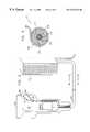
- FIG. 3is a simplified pictorial illustration of the probe assembly of FIG. 2;
- FIG. 4is a sectional illustration of a coaxial cable forming part of the probe assembly of FIG. 3, taken along lines IV—IV in FIG. 3;
- FIG. 5is a simplified flow chart illustration of three-dimensional data acquisition in the embodiment of FIGS. 1-4;
- FIG. 6is a simplified flow chart illustration of a two-dimensional image acquisition step shown in the flow chart of FIG. 5;
- FIG. 7is a simplified flow chart illustration of an embedding step shown in the flow chart of FIG. 5;
- FIG. 8is a simplified block diagram illustration of a probe assembly forming part of the system of FIG. 1 in accordance with an alternative embodiment of the present invention
- FIG. 9is a simplified pictorial illustration of the probe assembly of FIG. 8;
- FIG. 10is a sectional illustration of a coaxial cable forming part of the probe assembly of FIG. 8, taken along lines X—X in FIG. 8;
- FIG. 11is a simplified flow chart illustration of three-dimensional data acquisition in the embodiment of FIGS. 8-10.
- FIG. 12is a simplified flow chart illustration of an embedding step shown in the flow chart of FIG. 11 .
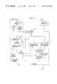
- FIG. 1is a simplified block diagram illustration of an ultrasonic imaging system constructed and operative in accordance with a preferred embodiment of the present invention.
- the systemmay be implemented in original equipment or as a retrofit to existing equipment having only two-dimensional imaging capabilities.
- An example of a retrofit existing systemis described hereinbelow with the understanding that the present invention applies equally to a non-retrofit implementation.
- an existing systemtypically a Model GE 3200 manufactured by General Electric Company of the U.S.A. or an UltraMark 4+ or HDI Series, both manufactured by ATL Inc. of Seattle, Wash., U.S.A.
- system electronics 100comprising a transducer interface port 102 and an image output port 104 .
- a video monitor 106 , a VCR 108 and a page printer 110are typically coupled to the image output port 104 .
- the inertial probe assembly 112in place of a conventional ultrasonic probe assembly, there is provided and coupled to port 102 an inertial probe assembly 112 , constructed and operative in accordance with a preferred embodiment of the present invention.
- the inertial probe assembly 112includes an inertial sensor 114 which is actuated by an operator-controlled switch 116 and typically provides at least an angular velocity output.
- the switch 116may be located on the probe, as illustrated. Alternatively it may be located elsewhere in the system.
- circuitry 120constructed and operative in accordance with a preferred embodiment of the present invention.
- Circuitry 120which is preferably embodied in a combination of hardware and software, typically comprises an integrator 122 , which receives the output of inertial sensor 114 .
- Video capture circuitry 124receives a video image output from image output port 104 of system electronics 100 and an inertial sensor operation indication output from switch 116 .
- Outputs from integrator 122 and from video capture circuitry 124are supplied to a 3D image generator 126 .
- the 3D image generator 126is operative to synchronize various two-dimensional images captured by circuitry 124 during a rotational sweep carried out by the probe assembly 112 about a fixed axis.
- 3D image generator 126The output of 3D image generator 126 is supplied to a 3D volume visualizer 130 , which may receive an optional input from a track ball controller 132 or other suitable input device and provides an output to video switching circuitry 134 .
- the output of 3D image generator 126may also be employed to carry out various measurements.
- Video switching circuitry 134also receives a video image output from system electronics 100 via image output port 104 and provides outputs to the video monitor 106 , VCR 108 and page printer 110 .
- Video switching circuitry 134may also provide switching of outputs of the VCR 108 to the video monitor 106 .
- FIG. 2is a simplified block diagram illustration of a preferred structure of a probe assembly 112 forming part of the system of FIG. 1 in accordance with one embodiment of the present invention.
- the probe assembly of FIG. 2preferably includes a transducer housing 200 within which is located a conventional ultrasonic transducer array 202 , such as a 128 element array which is commercially available from Sonora Medical Systems, Inc. of Longmont, Colo.
- angle tracker 204there is also provided within the transducer housing 200 an angle tracker 204 , such as a Two-Axis Angular-Rate Gyro (TAARG) commercially available from Rafael of Israel and described in U.S. Pat. No. 4,930,365, the disclosure of which is hereby incorporated by reference.
- Angle tracker 204corresponds to inertial sensor 114 (FIG. 1 ).
- a manually operable ON-OFF switch 206which corresponds to switch 116 (FIG. 1 ).
- a LED 208is associated with switch 206 , to indicate when the system is ready for data acquisition and thus that information provided by the angle tracker 204 is being acquired.
- the LED 208may be located elsewhere in the system or any other suitable type of indicator may be provided.
- the transducer housing 200 and its internal componentsare coupled via a connector cable 210 to a multifunctional connector 212 .
- the multifunctional connector 212is illustrated in FIG. 3 and the cable 210 is illustrated in section in FIG. 4 .
- the connector cable 210preferably includes at the interior thereof angle tracker actuation and output cables 214 and 216 as well as a switch status cable 218 and a LED actuation cable 220 . These cables are surrounded by a shield 222 and outwardly thereof by a collection of typically 128 transducer output cables 224 and by an outer cable shield 226 . Where the switch 116 and LED 208 are not part of the probe assembly 112 , cables 218 and 220 may be obviated in the connector cable 210 .
- Multifunctional connector 212typically includes a 156 pin array 230 , as seen in FIG. 3, which is preferably plug compatible with conventional transducer interface ports 102 of conventional system electronics 100 of conventional ultrasonic imaging systems such as Model GE 3200 manufactured by General Electric Company of the U.S.A. or an UltraMark 4+, manufactured by ATL Inc. of Seattle, Wash., U.S.A.
- multifunctional connector 212may include multiplexing electronics 232 which is usually employed in connectors which are conventionally connected to conventional transducer interface ports 102 of conventional system electronics 100 of some conventional ultrasonic imaging systems such as Model GE 3200 manufactured by General Electric company of the U.S.A.
- Multifunctional connector 212preferably also includes tracker electronics 234 including actuation generation and sensor processing.
- Tracker electronics 234 suitable for use with angle tracker 204is commercially available from Rafael of Israel, as part of the Two-Axis Angular-Rate Gyro (TAARG), described in U.S. Pat. No. 4,930,365.
- the output of tracker electronics 234is preferably the angular velocity output which is supplied to integrator 122 .
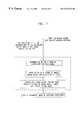
- FIG. 5is a simplified flow chart illustration of three-dimensional data acquisition in the embodiment of FIGS. 1-4.
- the inertial probe assembly 112(FIG. 1) including angle tracker 204 (FIG. 2) is positioned by an operator relative to a patient for 3 dimensional image acquisition.
- the video capture circuitry 124captures 2D images and the integrator 122 (FIG. 1) integrates angular velocities derived from the angle tracker 204 to obtain the relative angular position of each acquired 2D image.
- Each 2D imageis thus tagged with a relative angular position and saved in a buffer.
- switch 206When the operator has finished a desired angular sweep about a fixed axis, he may operate switch 206 to terminate 2D image acquisition.
- the acquired and duly tagged 2D imagesare then embedded in a 3D volume.
- the operatormay then select regions of interest within the 3D volume, preferably in accordance with the teachings of U.S. patent applications Ser. Nos. 09/351,252 and 09/352,002, both filed Jul. 12, 1999, the disclosure of which is hereby incorporated by reference.
- a 3D video image of the selected region of interest from a selected viewpointmay then be generated by conventional technique, for example as discussed in “Efficient Ray Tracing of Volume Data”, by M. Levoy, ACM Transactions on Graphics, Vol. 9, No. 3, pp 245-261, 1990, the disclosure of which is hereby incorporated by reference.
- FIG. 6is a simplified flow chart illustration of a typical two-dimensional image acquisition step shown in the flow chart of FIG. 5 .
- the 2D image acquisition stepmay be entirely conventional, as known in the prior art.
- Multiplexing electronicsis preferably employed for selecting an appropriate subset of transducer elements.
- the selected transducer elementsare pulsed with appropriate relative delays to form a focused acoustic beam.
- the received echoes from a transmitted acoustic beamare amplified , delayed and summed to provide a spatially focused receive beam.
- Consecutive time samples of the receive acoustic beamform a line of image information which is stored.
- FIG. 7is a simplified flow chart illustration of an embedding step shown in the flow chart of FIG. 5 .
- the input to the functionality of FIG. 7is a series of stored 2D images which are tagged with relative angular position information.
- the desired output from the functionality of FIG. 7is a 3D volumetric image preferably defined in Cartesian coordinates which includes the volume within the patient scanned by the operator rotating the inertial probe assembly about the fixed axis through a given range of angles.
- FIG. 8is a simplified block diagram illustration of a preferred structure of a probe assembly 112 forming part of the system of FIG. 1 in accordance with another embodiment of the present invention.
- the probe assembly of FIG. 8preferably includes a transducer housing 300 within which is located a conventional ultrasonic transducer array 302 , such as a 128 element array which is commercially available from Sonora Medical Systems, Inc. of Longmont, Colo.
- a multiple degree of freedom tracker 304such as a suitable combination of multiple angle trackers, such as a Two-Axis Angular-Rate Gyro (TAARG) commercially available from Rafael of Israel and described in U.S. Pat. No. 4,930,365.
- This multiple degree of freedom trackercorresponds to inertial sensor 114 (FIG. 1 ).
- the inertial sensormay include a micro-mechanical device.
- the inertial sensormay also include a sensor employing the Coriolis force.
- a manually operable ON-OFF switch 306which corresponds to switch 116 (FIG. 1 ).
- a LED 308is associated with switch 306 , to indicate when switch 306 is in the ON position and thus that information provided by the multiple degree of freedom tracker 304 is being acquired.
- the LED 308may be located elsewhere in the system.
- any other suitable indicatormay be employed.
- the transducer housing 300 and its internal componentsare coupled via a connector cable 310 to a multifunctional connector 312 .
- the multifunctional connector 312is illustrated in FIG. 9 and the cable 310 is illustrated in section in FIG. 10 .
- the connector cable 310preferably includes at the interior thereof multiple degree of freedom tracker actuation and output cables 314 and 316 as well as a switch status cable 318 and a LED actuation cable 320 . These cables are surrounded by a shield 322 and outwardly thereof by a collection of typically 128 transducer output cables 324 and by an outer cable shield 326 . Where the switch 306 and LED 308 are not part of the probe assembly 112 (FIG. 1 ), cables 318 and 320 may be obviated in the connector cable 310 .
- Multifunctional connector 312typically includes a 156 pin array 330 , as seen in FIG. 9, which is preferably plug compatible with conventional transducer interface ports 102 (FIG. 1) of conventional system electronics 100 (FIG. 1) of conventional ultrasonic imaging systems such as Model GE 3200 manufactured by General Electric Company of the U.S.A. or a UltraMark 4+ or HDI 3000, both manufactured by ATL Inc. of Seattle, Wash., U.S.A.
- multifunctional connector 312may include multiplexing electronics 332 which is usually employed in connectors which are conventionally connected to conventional transducer interface ports 102 (FIG. 1) of conventional system electronics 100 (FIG. 1) of some conventional ultrasonic imaging systems such as Model GE 3200 manufactured by General Electric Company of the U.S.A.
- Multifunctional connector 312preferably also includes tracker electronics 334 including actuation generation and sensor processing.
- Tracker electronics 334 suitable for use with multiple degree of freedom tracker 304may constitute a suitable combination of tracker electronics commercially available from Rafael of Israel as part of a Two-Axis Angular-Rate Gyro (TAARG) commercially available from Rafael of Israel and described in U.S. Pat. No. 4,930,365.
- the output of tracker electronics 334preferably includes an angular velocity output and other positional information, which is supplied to integrator 122 (FIG. 1 ).
- FIG. 11is a simplified flow chart illustration of three-dimensional data acquisition in the embodiment of FIGS. 8-10.
- the inertial probe assembly 112(FIG. 1) including multiple degree of freedom tracker 304 (FIG. 8) is positioned by an operator relative to a patient for 3 dimensional image acquisition.
- the video capture circuitry 124captures 2D images and the integrator 122 (FIG. 1) employs position information derived from the multiple degree of freedom tracker 304 to obtain the relative position of each acquired 2D image.
- Each 2D imageis thus tagged with a relative position and saved in a buffer.
- switch 306When the operator has finished a desired sweep, he may operate switch 306 to terminate 3D image acquisition.
- the acquired and duly tagged 2D imagesare then embedded in a 3D volume.
- the operatormay then select regions of interest within the 3D volume, preferably in accordance with the teachings of U.S. patent applications Ser. Nos. 09/351,252 and 09/352,002, both filed Jul. 12, 1999, the disclosure of which is hereby incorporated by reference.
- a 3D video or other image of the selected region of interest from a selected viewpointmay then be generated by conventional techniques, for example as discussed in “Efficient Ray Tracing of Volume Data”, by M. Levoy, ACM Transactions on Graphics, Vol. 9, No. 3, pp 245-261, 1990, the disclosure of which is hereby incorporated by reference.
- the 2D image acquisition stepmay be entirely conventional, as known in the prior art and as described hereinabove with respect to FIG. 6 .
- FIG. 12is a simplified flow chart illustration of an embedding step shown in the flow chart of FIG. 11 .
- the input to the functionality of FIG. 12is a series of stored 2D images which are tagged with relative position information.
- the desired output from the functionality of FIG. 12is a 3D volumetric image preferably defined in Cartesian coordinates which includes the volume within the patient scanned by the operator.
Landscapes
- Engineering & Computer Science (AREA)
- Health & Medical Sciences (AREA)
- Life Sciences & Earth Sciences (AREA)
- Physics & Mathematics (AREA)
- Remote Sensing (AREA)
- Radar, Positioning & Navigation (AREA)
- Acoustics & Sound (AREA)
- Medical Informatics (AREA)
- General Health & Medical Sciences (AREA)
- Heart & Thoracic Surgery (AREA)
- Radiology & Medical Imaging (AREA)
- Molecular Biology (AREA)
- Surgery (AREA)
- Animal Behavior & Ethology (AREA)
- Biomedical Technology (AREA)
- Public Health (AREA)
- Veterinary Medicine (AREA)
- Biophysics (AREA)
- Nuclear Medicine, Radiotherapy & Molecular Imaging (AREA)
- Pathology (AREA)
- General Physics & Mathematics (AREA)
- Computer Networks & Wireless Communication (AREA)
- Ultra Sonic Daignosis Equipment (AREA)
Abstract
Description
Claims (35)
Priority Applications (3)
| Application Number | Priority Date | Filing Date | Title |
|---|---|---|---|
| US09/421,046US6315724B1 (en) | 1999-10-19 | 1999-10-19 | 3-dimensional ultrasonic imaging |
| PCT/IL2000/000583WO2001028426A1 (en) | 1999-10-19 | 2000-09-19 | 3-dimensional ultrasonic imaging |
| AU73104/00AAU7310400A (en) | 1999-10-19 | 2000-09-19 | 3-dimensional ultrasonic imaging |
Applications Claiming Priority (1)
| Application Number | Priority Date | Filing Date | Title |
|---|---|---|---|
| US09/421,046US6315724B1 (en) | 1999-10-19 | 1999-10-19 | 3-dimensional ultrasonic imaging |
Publications (1)
| Publication Number | Publication Date |
|---|---|
| US6315724B1true US6315724B1 (en) | 2001-11-13 |
Family
ID=23668967
Family Applications (1)
| Application Number | Title | Priority Date | Filing Date |
|---|---|---|---|
| US09/421,046Expired - LifetimeUS6315724B1 (en) | 1999-10-19 | 1999-10-19 | 3-dimensional ultrasonic imaging |
Country Status (3)
| Country | Link |
|---|---|
| US (1) | US6315724B1 (en) |
| AU (1) | AU7310400A (en) |
| WO (1) | WO2001028426A1 (en) |
Cited By (21)
| Publication number | Priority date | Publication date | Assignee | Title |
|---|---|---|---|---|
| WO2004091418A1 (en)* | 2003-04-15 | 2004-10-28 | Dror Nir | Method and system for selecting and recording biopsy sites in a body organ |
| US20050119572A1 (en)* | 2003-10-10 | 2005-06-02 | Angelsen Bjorn A. | Probe for 3-dimensional scanning and focusing of an ultrasound beam |
| US20070038112A1 (en)* | 2001-10-16 | 2007-02-15 | Taylor James D | Scanning probe with integrated electronics |
| US20090306509A1 (en)* | 2005-03-30 | 2009-12-10 | Worcester Polytechnic Institute | Free-hand three-dimensional ultrasound diagnostic imaging with position and angle determination sensors |
| WO2010150148A1 (en)* | 2009-06-23 | 2010-12-29 | Koninklijke Philips Electronics N.V. | Position determining system |
| US20110085720A1 (en)* | 2009-05-14 | 2011-04-14 | Superdimension, Ltd. | Automatic Registration Technique |
| US8758256B2 (en) | 2010-07-12 | 2014-06-24 | Best Medical International, Inc. | Apparatus for brachytherapy that uses a scanning probe for treatment of malignant tissue |
| US9044216B2 (en) | 2010-07-12 | 2015-06-02 | Best Medical International, Inc. | Biopsy needle assembly |
| US20160121142A1 (en)* | 2014-11-05 | 2016-05-05 | Kona Medical, Inc. | Systems and methods for real-time tracking of a target tissue using imaging before and during therapy delivery |
| US9474505B2 (en) | 2012-03-16 | 2016-10-25 | Toshiba Medical Systems Corporation | Patient-probe-operator tracking method and apparatus for ultrasound imaging systems |
| US20170079549A1 (en)* | 2011-09-06 | 2017-03-23 | Ezono Ag | Imaging probe and method of obtaining position and/or orientation information |
| CN107991391A (en)* | 2017-10-27 | 2018-05-04 | 东莞理工学院 | A three-dimensional ultrasonic non-destructive testing system and method for automatic positioning and imaging |
| US20180153504A1 (en)* | 2015-06-08 | 2018-06-07 | The Board Of Trustees Of The Leland Stanford Junior University | 3d ultrasound imaging, associated methods, devices, and systems |
| CN108369268A (en)* | 2015-12-14 | 2018-08-03 | 皇家飞利浦有限公司 | System and method for medical supply tracking |
| US10434278B2 (en) | 2013-03-05 | 2019-10-08 | Ezono Ag | System for image guided procedure |
| US10722217B2 (en)* | 2016-05-26 | 2020-07-28 | Canon Medical Systems Corporation | Ultrasonic diagnostic apparatus and medical image processing apparatus |
| US10945706B2 (en) | 2017-05-05 | 2021-03-16 | Biim Ultrasound As | Hand held ultrasound probe |
| US11006852B2 (en) | 2017-12-11 | 2021-05-18 | Covidien Lp | Systems, methods, and computer-readable media of estimating thoracic cavity movement during respiration |
| US11660069B2 (en) | 2017-12-19 | 2023-05-30 | Koninklijke Philips N.V. | Combining image based and inertial probe tracking |
| US11844654B2 (en) | 2019-08-19 | 2023-12-19 | Caption Health, Inc. | Mid-procedure view change for ultrasound diagnostics |
| US20240074738A1 (en)* | 2020-12-18 | 2024-03-07 | Koninklijke Philips N.V. | Ultrasound image-based identification of anatomical scan window, probe orientation, and/or patient position |
Families Citing this family (3)
| Publication number | Priority date | Publication date | Assignee | Title |
|---|---|---|---|---|
| KR100961853B1 (en)* | 2007-02-14 | 2010-06-09 | 주식회사 메디슨 | Ultrasound systems |
| WO2015142306A1 (en) | 2014-03-20 | 2015-09-24 | Ozyegin Universitesi | Method and system related to a portable ultrasonic imaging system |
| CN114533111A (en)* | 2022-01-12 | 2022-05-27 | 电子科技大学 | Three-dimensional ultrasonic reconstruction system based on inertial navigation system |
Citations (10)
| Publication number | Priority date | Publication date | Assignee | Title |
|---|---|---|---|---|
| US4458536A (en) | 1982-07-06 | 1984-07-10 | The Charles Stark Draper Laboratory, Inc. | Multiaxial vibration sensor |
| US4930365A (en) | 1987-01-09 | 1990-06-05 | Itzhak Porat | Two axis rate gyroscope |
| US4932414A (en) | 1987-11-02 | 1990-06-12 | Cornell Research Foundation, Inc. | System of therapeutic ultrasound and real-time ultrasonic scanning |
| US5039035A (en) | 1989-05-03 | 1991-08-13 | Smiths Industries Public Limited Company | Helmet assembly with inflatable actuators |
| US5071160A (en) | 1989-10-02 | 1991-12-10 | Automotive Systems Laboratory, Inc. | Passenger out-of-position sensor |
| US5398691A (en) | 1993-09-03 | 1995-03-21 | University Of Washington | Method and apparatus for three-dimensional translumenal ultrasonic imaging |
| US5764014A (en) | 1996-02-01 | 1998-06-09 | Mannesmann Dematic Rapistan Corp. | Automated guided vehicle having ground track sensor |
| US5817022A (en) | 1995-03-28 | 1998-10-06 | Sonometrics Corporation | System for displaying a 2-D ultrasound image within a 3-D viewing environment |
| US5836869A (en) | 1994-12-13 | 1998-11-17 | Olympus Optical Co., Ltd. | Image tracking endoscope system |
| US5875257A (en) | 1997-03-07 | 1999-02-23 | Massachusetts Institute Of Technology | Apparatus for controlling continuous behavior through hand and arm gestures |
Family Cites Families (2)
| Publication number | Priority date | Publication date | Assignee | Title |
|---|---|---|---|---|
| GB9025431D0 (en)* | 1990-11-22 | 1991-01-09 | Advanced Tech Lab | Three dimensional ultrasonic imaging |
| US6122538A (en)* | 1997-01-16 | 2000-09-19 | Acuson Corporation | Motion--Monitoring method and system for medical devices |
- 1999
- 1999-10-19USUS09/421,046patent/US6315724B1/ennot_activeExpired - Lifetime
- 2000
- 2000-09-19AUAU73104/00Apatent/AU7310400A/ennot_activeAbandoned
- 2000-09-19WOPCT/IL2000/000583patent/WO2001028426A1/enactiveApplication Filing
Patent Citations (10)
| Publication number | Priority date | Publication date | Assignee | Title |
|---|---|---|---|---|
| US4458536A (en) | 1982-07-06 | 1984-07-10 | The Charles Stark Draper Laboratory, Inc. | Multiaxial vibration sensor |
| US4930365A (en) | 1987-01-09 | 1990-06-05 | Itzhak Porat | Two axis rate gyroscope |
| US4932414A (en) | 1987-11-02 | 1990-06-12 | Cornell Research Foundation, Inc. | System of therapeutic ultrasound and real-time ultrasonic scanning |
| US5039035A (en) | 1989-05-03 | 1991-08-13 | Smiths Industries Public Limited Company | Helmet assembly with inflatable actuators |
| US5071160A (en) | 1989-10-02 | 1991-12-10 | Automotive Systems Laboratory, Inc. | Passenger out-of-position sensor |
| US5398691A (en) | 1993-09-03 | 1995-03-21 | University Of Washington | Method and apparatus for three-dimensional translumenal ultrasonic imaging |
| US5836869A (en) | 1994-12-13 | 1998-11-17 | Olympus Optical Co., Ltd. | Image tracking endoscope system |
| US5817022A (en) | 1995-03-28 | 1998-10-06 | Sonometrics Corporation | System for displaying a 2-D ultrasound image within a 3-D viewing environment |
| US5764014A (en) | 1996-02-01 | 1998-06-09 | Mannesmann Dematic Rapistan Corp. | Automated guided vehicle having ground track sensor |
| US5875257A (en) | 1997-03-07 | 1999-02-23 | Massachusetts Institute Of Technology | Apparatus for controlling continuous behavior through hand and arm gestures |
Non-Patent Citations (6)
| Title |
|---|
| "Efficient Ray Tracing of Volume Data", M. Levoy, ACM Transactions on Graphics, vol. 9, No. 3, pp. 245-261, 1990. |
| AC3C61-"Curved Array General Imaging Scanhead", Specifications, Acoustic Research Systems, Inc., Longmont, Colorado, 1999. |
| AC3C61—"Curved Array General Imaging Scanhead", Specifications, Acoustic Research Systems, Inc., Longmont, Colorado, 1999. |
| Rafael "Two-Axis Angular-Rate Gyro-System Description", Haifa, Israel. |
| Rafael "Two-Axis Angular-Rate Gyro—System Description", Haifa, Israel. |
| Sonora Medical Systems, "RT 3200 Advantage II Ultrasound System for Obstetrics and Gynecology", 1999. |
Cited By (34)
| Publication number | Priority date | Publication date | Assignee | Title |
|---|---|---|---|---|
| US20070038112A1 (en)* | 2001-10-16 | 2007-02-15 | Taylor James D | Scanning probe with integrated electronics |
| US8137279B2 (en)* | 2001-10-16 | 2012-03-20 | Envisioneering, Llc | Scanning probe |
| WO2004091418A1 (en)* | 2003-04-15 | 2004-10-28 | Dror Nir | Method and system for selecting and recording biopsy sites in a body organ |
| US20050119572A1 (en)* | 2003-10-10 | 2005-06-02 | Angelsen Bjorn A. | Probe for 3-dimensional scanning and focusing of an ultrasound beam |
| US7691060B2 (en)* | 2003-10-10 | 2010-04-06 | Angelsen Bjoern A J | Probe for 3-dimensional scanning and focusing of an ultrasound beam |
| US20090306509A1 (en)* | 2005-03-30 | 2009-12-10 | Worcester Polytechnic Institute | Free-hand three-dimensional ultrasound diagnostic imaging with position and angle determination sensors |
| US20110085720A1 (en)* | 2009-05-14 | 2011-04-14 | Superdimension, Ltd. | Automatic Registration Technique |
| WO2010150148A1 (en)* | 2009-06-23 | 2010-12-29 | Koninklijke Philips Electronics N.V. | Position determining system |
| CN102460205A (en)* | 2009-06-23 | 2012-05-16 | 皇家飞利浦电子股份有限公司 | Position determining system |
| US9044216B2 (en) | 2010-07-12 | 2015-06-02 | Best Medical International, Inc. | Biopsy needle assembly |
| US8758256B2 (en) | 2010-07-12 | 2014-06-24 | Best Medical International, Inc. | Apparatus for brachytherapy that uses a scanning probe for treatment of malignant tissue |
| US10765343B2 (en)* | 2011-09-06 | 2020-09-08 | Ezono Ag | Imaging probe and method of obtaining position and/or orientation information |
| US20170079549A1 (en)* | 2011-09-06 | 2017-03-23 | Ezono Ag | Imaging probe and method of obtaining position and/or orientation information |
| US10674935B2 (en) | 2011-09-06 | 2020-06-09 | Ezono Ag | Imaging probe and method of obtaining position and/or orientation information |
| US10758155B2 (en) | 2011-09-06 | 2020-09-01 | Ezono Ag | Imaging probe and method of obtaining position and/or orientation information |
| US9474505B2 (en) | 2012-03-16 | 2016-10-25 | Toshiba Medical Systems Corporation | Patient-probe-operator tracking method and apparatus for ultrasound imaging systems |
| US10434278B2 (en) | 2013-03-05 | 2019-10-08 | Ezono Ag | System for image guided procedure |
| US20160121142A1 (en)* | 2014-11-05 | 2016-05-05 | Kona Medical, Inc. | Systems and methods for real-time tracking of a target tissue using imaging before and during therapy delivery |
| US12133765B2 (en) | 2014-11-05 | 2024-11-05 | Otsuka Medical Devices Co., Ltd. | Systems and methods for real-time tracking of a target tissue using imaging before and during therapy delivery |
| US10925579B2 (en)* | 2014-11-05 | 2021-02-23 | Otsuka Medical Devices Co., Ltd. | Systems and methods for real-time tracking of a target tissue using imaging before and during therapy delivery |
| US20180153504A1 (en)* | 2015-06-08 | 2018-06-07 | The Board Of Trustees Of The Leland Stanford Junior University | 3d ultrasound imaging, associated methods, devices, and systems |
| CN108369268A (en)* | 2015-12-14 | 2018-08-03 | 皇家飞利浦有限公司 | System and method for medical supply tracking |
| US10930007B2 (en) | 2015-12-14 | 2021-02-23 | Koninklijke Philips N.V. | System and method for medical device tracking |
| CN108369268B (en)* | 2015-12-14 | 2022-10-18 | 皇家飞利浦有限公司 | System and method for medical device tracking |
| US10722217B2 (en)* | 2016-05-26 | 2020-07-28 | Canon Medical Systems Corporation | Ultrasonic diagnostic apparatus and medical image processing apparatus |
| US10945706B2 (en) | 2017-05-05 | 2021-03-16 | Biim Ultrasound As | Hand held ultrasound probe |
| US11744551B2 (en) | 2017-05-05 | 2023-09-05 | Biim Ultrasound As | Hand held ultrasound probe |
| CN107991391A (en)* | 2017-10-27 | 2018-05-04 | 东莞理工学院 | A three-dimensional ultrasonic non-destructive testing system and method for automatic positioning and imaging |
| US11006852B2 (en) | 2017-12-11 | 2021-05-18 | Covidien Lp | Systems, methods, and computer-readable media of estimating thoracic cavity movement during respiration |
| US11779241B2 (en) | 2017-12-11 | 2023-10-10 | Covidien Lp | Systems, methods, and computer-readable media of estimating thoracic cavity movement during respiration |
| US11660069B2 (en) | 2017-12-19 | 2023-05-30 | Koninklijke Philips N.V. | Combining image based and inertial probe tracking |
| US11844654B2 (en) | 2019-08-19 | 2023-12-19 | Caption Health, Inc. | Mid-procedure view change for ultrasound diagnostics |
| US20240074738A1 (en)* | 2020-12-18 | 2024-03-07 | Koninklijke Philips N.V. | Ultrasound image-based identification of anatomical scan window, probe orientation, and/or patient position |
| US12402863B2 (en)* | 2020-12-18 | 2025-09-02 | Koninklijke Philips N.V. | Ultrasound image-based identification of anatomical scan window, probe orientation, and/or patient position |
Also Published As
| Publication number | Publication date |
|---|---|
| AU7310400A (en) | 2001-04-30 |
| WO2001028426A1 (en) | 2001-04-26 |
Similar Documents
| Publication | Publication Date | Title |
|---|---|---|
| US6315724B1 (en) | 3-dimensional ultrasonic imaging | |
| EP0511012B1 (en) | Ultrasound doppler position sensing | |
| US6443896B1 (en) | Method for creating multiplanar ultrasonic images of a three dimensional object | |
| US6048312A (en) | Method and apparatus for three-dimensional ultrasound imaging of biopsy needle | |
| KR100718411B1 (en) | Imaging System and Image Display Method | |
| CN100487482C (en) | Biplane ultrasonic imaging obtained by using time-cross data | |
| EP0487339B1 (en) | Acquisition and display of ultrasonic images from sequentially orientated image planes | |
| EP0966691B1 (en) | System for displaying a 2-d ultrasound image within a 3-d viewing environment | |
| JP4536869B2 (en) | Imaging system and imaging method | |
| Von Ramm et al. | High-speed ultrasound volumetric imaging system. II. Parallel processing and image display | |
| Carr | Surface reconstruction in 3D medical imaging | |
| EP1543346B1 (en) | Biplane ultrasonic imaging with icon depicting the mutual plane orientation | |
| US8562531B2 (en) | Ultrasonic motion detecting device, and image producing device and ultrasonic therapeutic using the detecting device | |
| US20090306509A1 (en) | Free-hand three-dimensional ultrasound diagnostic imaging with position and angle determination sensors | |
| US20070255137A1 (en) | Extended volume ultrasound data display and measurement | |
| CN109223030A (en) | Handheld three-dimensional ultrasonic imaging system and method | |
| US20200093464A1 (en) | Ultrasound Three-Dimensional (3-D) Segmentation | |
| EP0326575A1 (en) | THREE-DIMENSIONAL IMAGING SYSTEM. | |
| US6306092B1 (en) | Method and apparatus for calibrating rotational offsets in ultrasound transducer scans | |
| JP4666899B2 (en) | Biplane ultrasound imaging | |
| JP3303149B2 (en) | Ultrasound diagnostic equipment | |
| Abbas et al. | MEMS Gyroscope and the Ego-Motion Estimation Information Fusion for the Low-Cost Freehand Ultrasound Scanner | |
| JP3576565B6 (en) | 2D ultrasound image display system in 3D viewing environment | |
| JPH0738855B2 (en) | Ultrasonic 3D image display | |
| JPS61154653A (en) | Probe for ultrasound diagnostic equipment |
Legal Events
| Date | Code | Title | Description |
|---|---|---|---|
| AS | Assignment | Owner name:BIOMEDICOM LTD., ISRAEL Free format text:ASSIGNMENT OF ASSIGNORS INTEREST;ASSIGNORS:BERMAN, MICHAEL;GESSERT, JAMES;MOORE, WAYNE;AND OTHERS;REEL/FRAME:010542/0950;SIGNING DATES FROM 19991012 TO 19991212 | |
| AS | Assignment | Owner name:BIOMEDICOM LTD., ISRAEL Free format text:PLEASE CORRECT THE FOURTH INVENTOR'S SURNAME TO RACHEL NECHUSHTAI;ASSIGNORS:BERMAN, MICHAEL;GESSERT, JAMES;MOORE, WAYNE;AND OTHERS;REEL/FRAME:011080/0193;SIGNING DATES FROM 19991012 TO 19991018 | |
| REMI | Maintenance fee reminder mailed | ||
| FPAY | Fee payment | Year of fee payment:4 | |
| SULP | Surcharge for late payment | ||
| REMI | Maintenance fee reminder mailed | ||
| LAPS | Lapse for failure to pay maintenance fees | ||
| REIN | Reinstatement after maintenance fee payment confirmed | ||
| LAPS | Lapse for failure to pay maintenance fees | Free format text:PATENT EXPIRED FOR FAILURE TO PAY MAINTENANCE FEES (ORIGINAL EVENT CODE: EXP.); ENTITY STATUS OF PATENT OWNER: LARGE ENTITY | |
| FP | Lapsed due to failure to pay maintenance fee | Effective date:20091113 | |
| FEPP | Fee payment procedure | Free format text:PETITION RELATED TO MAINTENANCE FEES FILED (ORIGINAL EVENT CODE: PMFP); ENTITY STATUS OF PATENT OWNER: LARGE ENTITY | |
| FEPP | Fee payment procedure | Free format text:PETITION RELATED TO MAINTENANCE FEES GRANTED (ORIGINAL EVENT CODE: PMFG); ENTITY STATUS OF PATENT OWNER: LARGE ENTITY | |
| AS | Assignment | Owner name:DAVIDSON, LIMOR, MRS., ISRAEL Free format text:ASSIGNMENT OF ASSIGNORS INTEREST;ASSIGNOR:BIOMEDICOM LTD. (ALSO KNOWN AS BIOMEDICOM CREATIVE BIO-MEDICAL COMPUTING LTD.);REEL/FRAME:026643/0304 Effective date:20110724 Owner name:GLUZMAN, YIGAL, MR., ISRAEL Free format text:ASSIGNMENT OF ASSIGNORS INTEREST;ASSIGNOR:BIOMEDICOM LTD. (ALSO KNOWN AS BIOMEDICOM CREATIVE BIO-MEDICAL COMPUTING LTD.);REEL/FRAME:026643/0304 Effective date:20110724 | |
| FPAY | Fee payment | Year of fee payment:8 | |
| SULP | Surcharge for late payment | ||
| PRDP | Patent reinstated due to the acceptance of a late maintenance fee | Effective date:20110912 | |
| STCF | Information on status: patent grant | Free format text:PATENTED CASE | |
| AS | Assignment | Owner name:SAMSUNG ELECTRONICS CO., LTD., KOREA, REPUBLIC OF Free format text:ASSIGNMENT OF ASSIGNORS INTEREST;ASSIGNORS:GLUZMAN, YIGAL;DAVIDSON, LIMOR;REEL/FRAME:027141/0688 Effective date:20111023 | |
| FEPP | Fee payment procedure | Free format text:PAYOR NUMBER ASSIGNED (ORIGINAL EVENT CODE: ASPN); ENTITY STATUS OF PATENT OWNER: LARGE ENTITY | |
| FPAY | Fee payment | Year of fee payment:12 |