US6315715B1 - Flexible inner liner for the working channel of an endoscope - Google Patents
Flexible inner liner for the working channel of an endoscopeDownload PDFInfo
- Publication number
- US6315715B1 US6315715B1US09/377,338US37733899AUS6315715B1US 6315715 B1US6315715 B1US 6315715B1US 37733899 AUS37733899 AUS 37733899AUS 6315715 B1US6315715 B1US 6315715B1
- Authority
- US
- United States
- Prior art keywords
- flexible
- external
- tubular member
- helical
- distal portion
- Prior art date
- Legal status (The legal status is an assumption and is not a legal conclusion. Google has not performed a legal analysis and makes no representation as to the accuracy of the status listed.)
- Expired - Lifetime
Links
Images


Classifications
- A—HUMAN NECESSITIES
- A61—MEDICAL OR VETERINARY SCIENCE; HYGIENE
- A61B—DIAGNOSIS; SURGERY; IDENTIFICATION
- A61B1/00—Instruments for performing medical examinations of the interior of cavities or tubes of the body by visual or photographical inspection, e.g. endoscopes; Illuminating arrangements therefor
- A61B1/012—Instruments for performing medical examinations of the interior of cavities or tubes of the body by visual or photographical inspection, e.g. endoscopes; Illuminating arrangements therefor characterised by internal passages or accessories therefor
- A61B1/018—Instruments for performing medical examinations of the interior of cavities or tubes of the body by visual or photographical inspection, e.g. endoscopes; Illuminating arrangements therefor characterised by internal passages or accessories therefor for receiving instruments
Definitions
- the present inventionrelates generally to endoscopes for diagnostic and therapeutic medical applications, as well as borescopes for industrial applications. More particularly, it relates to a disposable flexible inner liner for the working channel of a flexible endoscope or borescope. The present invention also relates to catheters for insertion into a body lumen or cavity with or without the guidance of an endoscope.
- Endoscopesare frequently used in a medical setting for diagnostic and therapeutic procedures. Borescopes, their industrial counterpart, are frequently used in industrial settings for internal inspection of machines and manufactured parts. Endoscopes and borescopes are sometimes manufactured with one or more working channels through the scope for passing instrumentation through for performing diagnostic or therapeutic procedures within the field of view of the scope.
- the working channel in an endoscopeis also sometimes referred to as the biopsy channel of the scope.
- the inner lineralso helps to avoid contamination of the interior of the scope by the instruments as they pass through the working channel. This is especially important in medical applications where the small diameter working channels may be difficult to clean and sterilize between uses.
- a sterile, disposable inner linercan be used to keep the working channel of the endoscope clean.
- the working channelcan be lined with a simple thin-walled tube without concern for the flexibility of the liner.
- the inner liner for the working channelmust be sufficiently flexible to bend with the scope without kinking or collapsing, which would compromise the inner lumen of the working channel.
- Flexible endoscopes and borescopesmay be made flexible along their entire length or they may be made with a flexible distal section and a relatively rigid proximal section. It is important that the flexible portion of the working channel liner be at least as long as the flexible section of the scope for which it is intended.
- the present inventionprovides an improved flexible inner liner for the working channel of flexible endoscopes and borescopes.
- endoscopes and borescopeswill both be referred to as endoscopes in the following detailed description of the invention.
- endoscopes and borescopeswill both be referred to as endoscopes in the following detailed description of the invention.
- cathetersembraces a wide variety of elongated, generally tubular, devices for insertion into a body lumen or cavity for diagnostic or therapeutic purposes. These include inter alia cardiovascular catheters, urology catheters, visceral catheters and catheter introducers. Catheters can be introduced into the body through the working channel of an endoscope or they can be introduced independently under endoscopic, fluoroscopic or ultrasonic guidance. The construction of the disposable flexible inner liner of the present invention will also be beneficial for the construction of many varieties of catheters.
- the present inventiontakes the form of an elongated tubular inner liner for the working channel of a flexible endoscope. At least a portion of the length of the elongated tubular inner liner is highly flexible so that it will freely bend with the flexible section of the endoscope.
- the flexible portion of the inner lineris specially treated to make it resistant to kinking or collapse when it bends with the flexible section of the endoscope.
- Various meansare disclosed for treating the flexible portion to make it flexible and kink resistant.
- a first embodiment of the flexible endoscope linerhas a convoluted flexible distal portion.
- the convoluted flexible distal portionhas an additional outer layer of a flexible polymer.
- a third embodiment of the flexible endoscope linerhas a helically convoluted flexible distal portion with an outer helical reinforcing coil.
- the helically convoluted flexible distal portionhas a helical reinforcing coil and an outer layer of a flexible polymer.
- a fifth embodiment of the flexible endoscope linerhas a helically threaded flexible distal portion.
- the helically threaded flexible distal portionhas an outer layer of a flexible polymer.
- the helically threaded flexible distal portionhas an outer helical reinforcing coil.
- the helically threaded flexible distal portionhas a helical reinforcing coil and an outer layer of a flexible polymer. Manufacturing methods for each of the embodiments are also disclosed.
- the various constructions and manufacturing methods described for the disposable flexible inner liner of the present inventionwill also be advantageous for constructing a flexible tubular member for use in a variety of catheters.
- the flexible tubular membermay be used alone, without significant modification, as a diagnostic or therapeutic catheter, a guiding catheter or a catheter introducer.
- the flexible tubular membermay also be used as one component of a more complex catheter device or a catheter system.
- a flexible tubular member built according to the disposable flexible inner liner constructionwill be especially useful as a catheter component where the advantages of flexibility, kink resistance and an uncompromised inner lumen are important to the catheter performance.
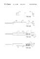
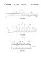
- FIG. 1Ashows a first embodiment of the flexible endoscope liner having a convoluted flexible distal portion.
- FIG. 1Bis an enlarged detail view of the convoluted flexible distal portion of the flexible endoscope liner of FIG. 1 A.
- FIG. 1Cis a cross section of the convoluted flexible distal portion of the flexible endoscope liner of FIG. 1 A.
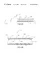
- FIG. 2Ashows a second embodiment of the flexible endoscope liner with a convoluted flexible distal portion having an outer layer of a flexible polymer.
- FIG. 2Bis a cross section of the flexible distal portion of the flexible endoscope liner of FIG. 2 A.
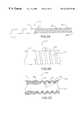
- FIGS. 3A, 3 B, 3 C and 3 Dare a series of drawings showing the fabrication steps for the flexible endoscope liners of FIGS. 1A and 2A.
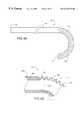
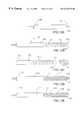
- FIG. 4Ashows the flexible endoscope liner of FIGS. 1A or 2 A bent into a curved configuration as it would be in use.
- FIG. 4Bis a cross section of the flexible distal portion of the flexible endoscope liner of FIG. 4A in the curved configuration.
- FIG. 5Ashows a third embodiment of the flexible endoscope liner with a helically convoluted flexible distal portion having an outer helical reinforcing coil.
- FIG. 5Bis an enlarged detail view of the flexible distal portion of the flexible endoscope liner of FIG. 5 A.
- FIG. 5Cis a cross section of the flexible distal portion of the flexible endoscope liner of FIG. 5 A.
- FIG. 6Ashows a fourth embodiment of the flexible endoscope liner with a helically convoluted flexible distal portion having a helical reinforcing coil and an outer layer of a flexible polymer.
- FIG. 6Bis a cross section of the flexible distal portion of the flexible endoscope liner of FIG. 6 A.
- FIGS. 7A, 7 B, 7 C, 7 D and 7 Eare a series of drawings showing the fabrication steps for the flexible endoscope liners of FIGS. 5A and 6A.
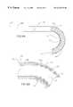
- FIG. 8Ashows the flexible endoscope liner of FIGS. 5A or 6 A bent to a curved configuration as it would be in use.
- FIG. 8Bis a cross section of the flexible distal portion of the flexible endoscope liner of FIG. 8A in the curved configuration.
- FIG. 9Ashows a fifth embodiment of the flexible endoscope liner having a helically threaded flexible distal portion.
- FIG. 9Bis an enlarged detail view of the flexible distal portion of the flexible endoscope liner of FIG. 9 A.
- FIG. 9Cis a cross section of the helically threaded flexible distal portion of the flexible endoscope liner of FIG. 9 A.
- FIG. 10Ashows a sixth embodiment of the flexible endoscope liner with a helically threaded flexible distal portion having an outer layer of a flexible polymer.
- FIG. 10Bis a cross section of the flexible distal portion of the flexible endoscope liner of FIG. 10 A.
- FIG. 11Ashows a seventh embodiment of the flexible endoscope liner with a helically threaded flexible distal portion having an outer helical reinforcing coil.
- FIG. 11Bis an enlarged detail view of the flexible distal portion of the flexible endoscope liner of FIG. 11 A.
- FIG. 11Cis a cross section of the flexible distal portion of the flexible endoscope liner of FIG. 11 A.
- FIG. 12Ashows an eighth embodiment of the flexible endoscope liner with a helically threaded flexible distal portion having a helical reinforcing coil and an outer layer of a flexible polymer.
- FIG. 12Bis a cross section of the flexible distal portion of the flexible endoscope liner of FIG. 12 A.
- FIGS. 13A, 13 B, 13 C, 13 D and 13 Eare a series of drawings showing the fabrication steps for the flexible endoscope liners of FIGS. 9A, 10 A, 11 A and 12 A.
- FIG. 14Ashows the flexible endoscope liner of FIGS. 9A, 10 A, 11 A or 12 A bent to a curved configuration as it would be in use.
- FIG. 14Bis a cross section of the flexible distal portion of the flexible endoscope liner of FIG. 14A in the curved configuration.
- FIG. 1Ashows a first embodiment of the flexible endoscope liner 100 of the present invention.
- the flexible endoscope liner 100is an elongated tubular member which includes a convoluted flexible distal portion 102 and a relatively inflexible proximal portion 104 .
- the flexible endoscope liner 100has a tubular construction with an inner lumen 110 which extends from the proximal end 116 to the distal end 118 of the flexible endoscope liner 100 through the relatively inflexible proximal portion 104 and the convoluted flexible distal portion 102 .
- the convoluted flexible distal portion 102 of the flexible endoscope liner 100is specially treated to increase its flexibility and to make it resistant to kinking or collapse when it bends with the flexible section of the endoscope.
- the overall length of the flexible endoscope liner 100is made to match the length of the working channel of the endoscope for which it is intended.
- the convoluted flexible distal portion 102should be at least as long as the flexible section of the endoscope, with the relatively inflexible proximal portion 104 making up the remainder of the length.
- the overall length of the flexible endoscope liner 100is between 30 and 250 cm, and the length of the convoluted flexible distal portion 102 is typically between 4 and 25 cm, but can extend the full length of the device.
- the convoluted flexible distal portion 102may extend the full length of the flexible endoscope liner 100 and the relatively inflexible proximal portion 104 may be totally absent.
- FIG. 1Bis an enlarged detail view of the flexible endoscope liner 100 of FIG. 1A showing the transition between the relatively inflexible proximal portion 104 and the convoluted flexible distal portion 102 .
- FIG. 1Cshows a longitudinal cross section of the transition between the relatively inflexible proximal portion 104 and the convoluted flexible distal portion 102 of the flexible endoscope liner 100 .
- the inner lumen 110is continuous through the relatively inflexible proximal portion 104 and the convoluted flexible distal portion 102 of the flexible endoscope liner 100 .
- the inner lumen 110is surrounded by a tubular proximal wall 106 .
- the inner lumen 110is surrounded by a tubular distal wall 108 which is folded into a convoluted configuration to increase its flexibility and to make it resistant to kinking or collapse so that the internal diameter of the inner lumen 110 is not compromised when it bends with the flexible section of the endoscope.
- the internal diameter of the inner lumen 110 and the external diameter of the flexible endoscope liner 100remain relatively constant throughout the length of the relatively inflexible proximal portion 104 and the convoluted flexible distal portion 102 of the flexible endoscope liner 100 .
- the relatively inflexible proximal portion 104is made with a relatively thick proximal wall 106 and a relatively thinner distal wall 108 so that the distal wall 108 can follow the convolutions and maintain the same external diameter at the peaks of the convolutions 112 and the same internal diameter at the troughs of the convolutions 114 as the thicker proximal wall 106 .
- the relatively thinner distal wall 108will have approximately 30-70 percent of the wall thickness of the thicker proximal wall 106 .
- Typical embodiments of the flexible endoscope liner 100will have a proximal portion 104 and a flexible distal portion 102 with an internal diameter of approximately 1.8-4.0 mm and an external diameter of approximately 2.0-4.5 mm.
- the internal diameter and external diametercan vary widely depending on the actual design of the endoscope for which the flexible endoscope liner 100 is intended.
- the proximal wall 106 and the distal wall 108are made from a continuous polymeric material. In other possible embodiments, the proximal wall 106 and the distal wall 108 may be made from dissimilar materials.
- polymeric materialsare suitable for construction of the proximal wall 106 and the distal wall 108 of the flexible endoscope liner 100 , including highly lubricious polymers, such as fluoropolymers (e.g. PTFE, EPTFE, PFA) and polyolefins, like polyethylene (e.g. LDPE, HDPE), polypropylene and polyolefin copolymers; high strength polymers, such as polyamides (e.g. nylon 11 , nylon 12 , polyamide copolymers); thermoplastic elastomers (e.g. polyurethane); and thermoset polymers.
- highly lubricious polymerssuch as fluoropolymers (e.g. PTFE, EPTFE, PFA) and polyolefins, like polyethylene (e.g. LDPE, HDPE), polypropylene and polyolefin copolymers
- high strength polymerssuch as polyamides (e.g. nylon 11 , nylon 12 , polyamide
- the proximal wall 106 and/or the distal wall 108 of the flexible endoscope liner 100may be made from a composite material, for example a thermoplastic or thermoset polymer matrix with wire or fiber reinforcement which may be braided, spiral wound, counterwound or randomly oriented within the matrix material.
- the proximal wall 106 and/or the distal wall 108may be made from multiple layers of tubing.
- the flexible endoscope liner 100may be made with an inner tubular layer of a highly lubricious polymer and an outer tubular layer of a polymer chosen for another desirable property, such as high strength or flexibility.
- lubricious coatingsmay also be added to the interior and/or exterior surfaces of the flexible endoscope liner 100 .
- FIG. 2Ashows a second embodiment of the flexible endoscope liner 200 which is a modification of the flexible endoscope liner 100 shown in FIG. 1 A.
- the flexible endoscope liner 200is an elongated tubular member with an inner lumen 210 which extends from the proximal end 216 to the distal end 218 .
- the flexible endoscope liner 200includes a relatively inflexible proximal portion 104 having a relatively thick proximal wall 206 and a convoluted flexible distal portion 202 having a thinner distal wall 208 which is folded into a convoluted configuration.
- FIG. 1Ashows a second embodiment of the flexible endoscope liner 200 which is a modification of the flexible endoscope liner 100 shown in FIG. 1 A.
- the flexible endoscope liner 200is an elongated tubular member with an inner lumen 210 which extends from the proximal end 216 to the distal end 218 .
- the flexible endoscope liner 200includes
- the convoluted flexible distal portion 202 of the flexible endoscope liner 200has an additional outer layer 220 of a flexible polymer.
- the flexible outer layer 220fills in between the peaks of the convolutions 212 on the convoluted flexible distal portion 202 to create a smooth exterior surface.
- Preferred materials for the flexible outer layer 220include flexible thermoplastic elastomers, such as ethylene vinyl acetate (EVA) or polyamide copolymers (e.g.
- PEBAX from ELF ATOCHEMand thermoplastic polyurethanes and flexible thermoset polymers, such as silicone, latex or thermoset polyurethanes.
- the hardness of the flexible outer layer 220 materialcan vary from approximately 50 Shore A durometer to approximately 35 Shore D durometer.
- FIGS. 3A, 3 B, 3 C and 3 Dare a series of drawings illustrating one preferred method for fabricating the flexible endoscope liners of FIGS. 1A and 2A.
- an extruded polymer tube 300is cut to an appropriate length and a straightened wire mandrel 304 is inserted into the inner lumen 302 of the tube 300 .
- the wire mandrel 304is preferably made of stainless steel or another nontoxic, high strength material.
- the external diameter of the wire mandrel 304should closely match the internal diameter of the inner lumen 302 with only about 1-3 thousandths of an inch clearance.
- a nontoxic lubricant or a lubricious coating, such as PTFE,may be used on the wire mandrel 304 to allow easy insertion and removal.
- one end of the tube 300is drawn to reduce its external diameter, thereby creating a drawn distal portion 306 and an undrawn proximal portion 308 .
- the drawing stepmay be performed by various means appropriate for the material chosen for the extruded polymer tube 300 .
- the drawn distal portion 306may be created by stretching one end of the extruded polymer tube 300 by hand or by machine, either at room temperature or at an elevated temperature.
- the drawn distal portion 306may be created by pulling one end of the extruded polymer tube 300 through a tapered die by hand or by machine, either at room temperature or at an elevated temperature.
- the drawn distal portion 306is axially compressed, as shown by arrows 310 , to create the convoluted flexible distal portion 312 .
- the axial compressioncauses the wall of the drawn distal portion 306 to fold into annular convolutions.
- the wire mandrel 304maintains the inner lumen 302 in the convoluted flexible distal portion 312 as the drawn distal portion 306 is compressed.
- a tubular mold(not shown) may be placed over the exterior of the drawn distal portion 306 as it is axially compressed to form the convoluted flexible distal portion 312 .
- the axial compression stepmay be performed at room temperature or at an elevated temperature.
- an additional stress relieving or annealing step at an elevated temperaturemay be required between the drawing step and the axial compression step.
- FIG. 3Dshows an optional fourth step of applying a flexible outer coating 314 to the convoluted flexible distal portion 312 .
- the flexible outer coating 314may be applied by dissolving a flexible polymer in an appropriate solvent and dipping, spraying or casting one or more layers of the polymer onto the convoluted flexible distal portion 312 .
- the resin and hardener of a flexible thermoset polymercan be mixed and applied to the convoluted flexible distal portion 312 as a liquid by dipping, spraying or casting.
- the flexible outer coating 314may also be applied by insert molding a thermoplastic elastomer over the convoluted flexible distal portion 312 .
- the wire mandrel 304is then withdrawn from the tube 300 and the proximal and distal ends are cut to the desired length to complete the flexible endoscope liner.
- FIG. 4Ashows the flexible endoscope liner 400 of the present invention bent into a curved configuration as it would be in actual clinical use.
- the flexible endoscope liner 400 shown in FIG. 4Ais representative of the flexible endoscope liner in either FIG. 1A ( 100 ) or FIG. 2A ( 200 ) in use.
- the flexible endoscope liner 400is inserted into the working channel of a flexible endoscope (not shown) before the endoscope is inserted into the patient's body through an incision or through a natural body orifice. Once in place, the flexible distal section of the endoscope may be flexed into a curved configuration to view various internal body structures.
- FIG. 4Bshows a longitudinal cross section of the transition between the relatively inflexible proximal portion 404 and the convoluted flexible distal portion 402 of the flexible endoscope liner 400 of FIG. 4A when it is in the curved configuration. As can be seen in the cross section of FIG.
- the flexible endoscope liner 400is made with a flexible outer coating 420 over the convoluted flexible distal portion 402 , the flexible outer coating 420 (shown in phantom lines) elastically deforms with the convoluted flexible distal portion 402 , compressing with the convolutions on the inside of the curve 412 and expanding with the convolutions on the outside of the curve 414 .
- FIG. 5Ashows a third embodiment of the flexible endoscope liner 500 with a helically convoluted flexible distal portion 502 having an outer helical reinforcing coil 522 .
- the flexible endoscope liner 500is an elongated tubular member with an inner lumen 510 which extends from the proximal end 516 , through a relatively inflexible proximal portion 504 and a flexible distal portion 502 , to the distal end 518 .
- FIG. 5Bis an enlarged detail view of the flexible endoscope liner 500 of FIG. 5A showing the transition between the relatively inflexible proximal portion 504 and the flexible distal portion 502 .
- 5Cshows a longitudinal cross section of the transition between the relatively inflexible proximal portion 504 and the flexible distal portion 502 of the flexible endoscope liner 500 .
- the present embodimenthas a helically convoluted flexible distal portion 502 which is reinforced with an outer helical reinforcing coil 522 .
- the outer helical reinforcing coil 522strengthens the thin distal wall 508 and increases the kink resistance of the helically convoluted flexible distal portion 502 without compromising its flexibility.
- Preferred materials for the proximal wall 506 and the distal wall 508 of the flexible endoscope liner 500include fluoropolymers, polyethylenes, polypropylenes, polyolefin copolymers, polyamides, polyamide copolymers, thermoplastic elastomers, polyurethanes, thermoset polymers and composite materials.
- the outer helical reinforcing coil 522is preferably made of a resilient, biocompatible, high strength filamentous material, such as metal wire, glass fibers, carbon fibers, high strength polymer fibers or filaments, or a composite material.
- the cross section of the outer helical reinforcing coil 522 filamentmay be circular, as shown, rectangular or any other convenient cross section.
- the filament diameter of the outer helical reinforcing coil 522is typically from about 0.004 inches to 0.015 inches.
- the outer diameter of the helical reinforcing coil 522is typically from about 1.8 mm to 5 mm.
- the outer helical reinforcing coil 522is made of series 300 stainless steel wire (e.g. 302 or 304 stainless steel).
- the stainless steel wire of the outer helical reinforcing coil 522is preferably used in a work hardened, unannealed condition (condition B) or slightly stress relieved to a spring temper, because the high strength and excellent resilience of the wire in this condition improves the flexibility characteristics and kink resistance of the helically convoluted flexible distal portion 502 .
- Annealed stainless steel wire or softer alloysare also usable for the outer helical reinforcing coil 522 , but it has been found that these softer, more malleable wires do not protect the helically convoluted flexible distal portion 502 as well from kinking or collapse.
- FIG. 6Ashows a fourth embodiment of the flexible endoscope liner 600 which is a modification of the flexible endoscope liner 500 shown in FIG. 5 A.
- the flexible endoscope liner 600is an elongated tubular member with an inner lumen 610 which extends from the proximal end 616 , through a relatively inflexible proximal portion 604 and a helically convoluted flexible distal portion 602 , to the distal end 618 .
- 6Bis a longitudinal cross section of the flexible endoscope liner 600 showing the transition between the relatively inflexible proximal portion 604 with its relatively thick proximal wall 606 and the helically convoluted flexible distal portion 602 with its thinner distal wall 608 which is reinforced with a outer helical reinforcing coil 622 .
- the helically convoluted flexible distal portion 602 of the flexible endoscope liner 600has an additional outer layer 620 of a flexible polymer.
- the flexible outer layer 620fills in between the peaks of the convolutions 612 and the coils of the outer helical reinforcing coil 622 to create a smooth exterior surface on the helically convoluted flexible distal portion 602 .
- Preferred materials for the flexible outer layer 620include flexible thermoplastic elastomers, such as ethylene vinyl acetate (EVA), polyamide copolymers (e.g. PEBAX from ELF ATOCHEM) and thermoplastic polyurethanes, and flexible thermoset polymers, such as silicone, latex or thermoset polyurethanes.
- EVAethylene vinyl acetate
- PEBAXpolyamide copolymers
- thermoplastic polyurethanessuch as silicone, latex or thermoset polyurethanes.
- the hardness of the flexible outer layer 620 materialcan vary from approximately 50 Shore A durometer to approximately 35 Shore D durometer.
- FIGS. 7A, 7 B, 7 C, 7 D and 7 Eare a series of drawings illustrating one preferred method for fabricating the flexible endoscope liners of FIGS. 5A and 6A.
- an extruded polymer tube 700is cut to an appropriate length and a straightened wire mandrel 704 is inserted into the inner lumen 702 of the tube 700 .
- the wire mandrel 704is preferably made of stainless steel or another nontoxic, high strength material.
- the external diameter of the wire mandrel 704should closely match the internal diameter of the inner lumen 702 with only about 1-3 thousandths of an inch clearance.
- a nontoxic lubricant or a lubricious coating, such as PTFE,may be used on the wire mandrel 704 to allow easy insertion and removal.
- one end of the tube 700is drawn to reduce its external diameter, thereby creating a drawn distal portion 706 and an undrawn proximal portion 708 .
- the drawing stepmay be performed by various means appropriate for the material chosen for the extruded polymer tube 700 .
- the drawn distal portion 706may be created by stretching one end of the extruded polymer tube 700 by hand or by machine, either at room temperature or at an elevated temperature.
- the drawn distal portion 706may be created by pulling one end of the extruded polymer tube 700 through a tapered die by hand or by machine, either at room temperature or at an elevated temperature.
- a previously made helical reinforcing coil 714 with separated coilsis placed over the drawn distal portion 706 .
- the helical reinforcing coil 714 and the drawn distal portion 706are axially compressed, as shown by arrows 710 .
- the wall of the drawn distal portion 706folds into a helically convoluted configuration between the coils of the helical reinforcing coil 714 to create the helically convoluted flexible distal portion 712 .
- the wire mandrel 704maintains the inner lumen 702 in the helically convoluted flexible distal portion 712 as the drawn distal portion 706 is compressed.
- a tubular mold(not shown) may be placed over the exterior of the drawn distal portion 706 as it is axially compressed to form the helically convoluted flexible distal portion 712 .
- the axial compression stepmay be performed at room temperature or at an elevated temperature.
- FIG. 7Eshows an optional fifth step of applying a flexible outer coating 716 to the convoluted flexible distal portion 712 .
- the flexible outer coating 716may be applied by dissolving a flexible polymer in an appropriate solvent and dipping, spraying or casting one or more layers of the polymer onto the helically convoluted flexible distal portion 712 .
- the resin and hardener of a flexible thermoset polymercan be mixed and applied to the helically convoluted flexible distal portion 712 as a liquid by dipping, spraying or casting.
- the flexible outer coating 716may also be applied by insert molding a thermoplastic elastomer over the helically convoluted flexible distal portion 712 .
- the wire mandrel 704is then withdrawn from the tube 700 and the proximal and distal ends are cut to the desired length to complete the flexible endoscope liner.
- FIG. 8Ashows the flexible endoscope liner 800 of the present invention bent into a curved configuration as it would be in actual clinical use.
- the flexible endoscope liner 800 shown in FIG. 8Ais representative of the flexible endoscope liner in either FIG. 5A ( 500 ) or FIG. 6A ( 600 ) in use.
- the flexible endoscope liner 800is inserted into the working channel of a flexible endoscope (not shown) before the endoscope is inserted into the patient's body through an incision or through a natural body orifice. Once in place, the flexible distal section of the endoscope may be flexed into a curved configuration to view various internal body structures.
- FIG. 8Bis a longitudinal cross section of the flexible endoscope liner 800 of FIG. 8A in the curved configuration, showing the transition between the relatively inflexible proximal portion 804 and the helically convoluted flexible distal portion 802 reinforced with an outer helical reinforcing coil 822 .
- FIG. 8Bis a longitudinal cross section of the flexible endoscope liner 800 of FIG. 8A in the curved configuration, showing the transition between the relatively inflexible proximal portion 804 and the helically convoluted flexible distal portion 802 reinforced with an outer helical reinforcing coil 822 .
- the flexible endoscope liner 800is made with a flexible outer coating 820 over the convoluted flexible distal portion 802 , the flexible outer coating 820 (shown in phantom lines) elastically deforms with the convoluted flexible distal portion 802 , compressing with the convolutions and the reinforcing coils on the inside of the curve 812 and expanding with the convolutions and the reinforcing coils on the outside of the curve 814 .
- FIG. 9Ashows a fifth embodiment of the flexible endoscope liner 900 having a helically threaded flexible distal portion 902 .
- the flexible endoscope liner 900is an elongated tubular member with an inner lumen 910 which extends from the proximal end 916 , through a relatively inflexible proximal portion 904 and a flexible distal portion 902 , to the distal end 918 .
- FIG. 9Bis an enlarged detail view of the flexible endoscope liner 900 of FIG. 9A showing the transition between the relatively inflexible proximal portion 904 and the flexible distal portion 902 .
- FIG. 9Ashows a fifth embodiment of the flexible endoscope liner 900 having a helically threaded flexible distal portion 902 .
- the flexible endoscope liner 900is an elongated tubular member with an inner lumen 910 which extends from the proximal end 916 , through a relatively inflexible prox
- FIGCshows a longitudinal cross section of the transition between the relatively inflexible proximal portion 904 and the flexible distal portion 902 of the flexible endoscope liner 900 .
- the present embodimenthas a helically threaded flexible distal portion 902 .
- the helically threaded flexible distal portion 902has an external reinforcing thread 912 that traces a helical path around the distal wall 908 of the flexible endoscope liner 900 .
- a land 914 having a reduced wall thicknesstraces a helical path around the distal wall 908 , separating adjacent turns of the reinforcing thread 912 .
- the width of the lands 914is typically 100-150 percent of the width of the external reinforcing thread 912 .
- the thickness of the distal wall 908 at the lands 914is approximately 60-80 percent of the total wall thickness measured at the peaks of the external reinforcing thread 912 .
- the external reinforcing thread 912may be made as a single helix, as shown in FIG. 9A, or as a double, triple or multiple helix.
- the external reinforcing thread 912may be made with a semicircular profile, as shown in FIG. 9C, or it may be made with a rectangular, triangular, trapezoidal, or semi-elliptical profile or other desired profile.
- proximal wall 906 of the relatively inflexible proximal portion 904 and the distal wall 908 and external reinforcing thread 912 of the helically threaded flexible distal portion 902are all formed integrally of a single polymeric material.
- An advantage of this embodimentis that it gives the inner lumen 910 of the flexible endoscope liner 900 a smooth, continuous inner surface 924 for smooth passage of instruments through the working lumen of the endoscope.
- Suitable materials for this embodiment of the flexible endoscope liner 900include fluoropolymers, polyethylenes, polypropylenes, polyolefin copolymers, polyamides, polyamide copolymers, thermoplastic elastomers, polyurethanes, thermoset polymers and composite materials.
- the overall length of the flexible endoscope liner 900is between 30 and 250 cm, and the length of the helically threaded flexible distal portion 102 is between 4 and 25 cm, with the relatively inflexible proximal portion 904 making up the remainder of the length.
- the flexible endoscope liner 900would be made with the helically threaded flexible distal portion 102 extending the full length of 415 the device.
- the external diameter of the helically threaded flexible distal portion 902is approximately the same as the external diameter of the relatively inflexible proximal portion 904 , although, in some applications it may be acceptable to have the external diameter of the helically threaded flexible distal portion 902 larger or smaller than the external diameter of the relatively inflexible proximal portion 904 .
- the relatively inflexible proximal portion 904 and the helically threaded flexible distal portion 902have an external diameter of approximately 2.0-4.5 mm and an internal diameter of approximately 1.82-4.0 mm. It should be noted, however, that the length dimensions and the internal and external diameters of the flexible endoscope liner 900 can vary widely depending on the actual design of the endoscope for which it is intended.
- FIG. 10Ashows a sixth embodiment of the flexible endoscope liner 1000 which is a modification of the flexible endoscope liner 900 shown in FIG. 9 A.
- the flexible endoscope liner 1000is an elongated tubular member with an inner lumen 1010 which extends from the proximal end 1016 , through a relatively inflexible proximal portion 1004 and a helically threaded flexible distal portion 1002 , to the distal end 1018 .
- FIG. 10Bis a longitudinal cross section of the flexible endoscope liner 1000 showing the transition between the relatively inflexible proximal portion 1004 and the helically threaded flexible distal portion 1102 .
- the relatively inflexible proximal portion 1004has a relatively thick proximal wall 1006 and the helically threaded flexible distal portion 1102 has a thinner distal wall 1008 reinforced by an external reinforcing thread 1012 .
- the helically threaded flexible distal portion 1002 of the flexible endoscope liner 1000has an additional outer layer 1020 of a flexible polymer.
- the flexible outer layer 1020fills in the lands 1014 between the peaks of the external reinforcing thread 1012 to create a smooth exterior surface on the helically threaded flexible distal portion 1002 .
- Preferred materials for the flexible outer layer 1020include flexible thermoplastic elastomers, such as ethylene vinyl acetate (EVA), polyamide copolymers (e.g. PEBAX from ELF ATOCHEM) and thermoplastic polyurethanes, and flexible thermoset polymers, such as silicone, latex or thermoset polyurethanes.
- EVAethylene vinyl acetate
- PEBAXpolyamide copolymers
- thermoplastic polyurethanessuch as silicone, latex or thermoset polyurethanes.
- the hardness of the flexible outer layer 1020 materialcan vary from approximately 50 Shore A durometer to approximately 35 Shore D durometer.
- FIG. 11Ashows a seventh embodiment of the flexible endoscope liner 1100 which is another modification of the flexible endoscope liner 900 shown in FIG. 9 A.
- the flexible endoscope liner 1100is an elongated tubular member with an inner lumen 1110 which extends from the proximal end 1116 , through a relatively inflexible proximal portion 1104 and a helically threaded flexible distal portion 1102 , to the distal end 1118 .
- FIG. 11Bis a longitudinal cross section of the flexible endoscope liner 1100 showing the transition between the relatively inflexible proximal portion 1104 and the helically threaded flexible distal portion 1102 .
- the relatively inflexible proximal portion 1104has a relatively thick proximal wall 1106 and the helically threaded flexible distal portion 1102 has a thinner distal wall 1108 reinforced by an external reinforcing thread 1112 .
- the helically threaded flexible distal portion 1102 of the flexible endoscope liner 1100has an additional outer helical reinforcing coil 1122 which occupies the lands 1114 between the peaks of the external reinforcing thread 1112 .
- the outer helical reinforcing coil 1122strengthens the thin distal wall 1108 and increases the kink resistance of the helically threaded flexible distal portion 1102 without compromising its flexibility.
- the outer helical reinforcing coil 1122is preferably made of a resilient, biocompatible, high strength filamentous material, such as metal wire, glass fibers, carbon fibers, high strength polymer fibers or filaments, or a composite material.
- the cross section of the outer helical reinforcing coil 1122may be rectangular, as shown, circular or any other convenient cross section. In a rectangular configuration, the filament width of the outer helical reinforcing coil 1122 is typically 0.008-0.020 inches and the thickness is typically 0.003-0.015 inches.
- the outer helical reinforcing coil 1122is made of rectangular cross section series 300 stainless steel wire (e.g. 302 or 304 stainless steel) with dimensions of approximately 0.015 by 0.004 inches.
- the outer helical reinforcing coil 1122is trimmed to length with a square cut proximal end 1126 and an angle cut distal end 1128 .
- the stainless steel wire of the outer helical reinforcing coil 1122is preferably used in a work hardened, unannealed condition (condition B) or slightly stress relieved to a spring temper, because the high strength and excellent resilience of the wire in this condition improves the flexibility characteristics and kink resistance of the helically convoluted flexible distal portion 1102 .
- Annealed stainless steel wire or softer alloysare also usable for the outer helical reinforcing coil 1122 , but it has been found that these softer, more malleable wires do not protect the helically convoluted flexible distal portion 1102 as well from kinking or collapse.
- FIG. 12Ashows an eighth embodiment of the flexible endoscope liner 1200 that combines the features of the flexible endoscope liners shown in FIG. 10A ( 1000 ) and FIG. 11A ( 1100 ).
- the flexible endoscope liner 1200is an elongated tubular member with an inner lumen 1220 which extends from the proximal end 1226 , through a relatively inflexible proximal portion 1204 and a helically threaded flexible distal portion 1202 , to the distal end 1228 .
- FIG. 12Bis a longitudinal cross section of the flexible endoscope liner 1200 showing the transition between the relatively inflexible proximal portion 1204 and the helically threaded flexible distal portion 1202 .
- the relatively inflexible proximal portion 1204has a relatively thick proximal wall 1206 and the helically threaded flexible distal portion 1202 has a thinner distal wall 1208 reinforced by an external reinforcing thread 1222 .
- the helically threaded flexible distal portion 1202 of the flexible endoscope liner 1200has an outer helical reinforcing coil 1222 which occupies the lands 1224 between the peaks of the external reinforcing thread 1222 .
- the outer helical reinforcing coil 1222strengthens the thin distal wall 1208 and increases the kink resistance of the helically threaded flexible distal portion 1202 without compromising its flexibility.
- the helically threaded flexible distal portion 1202 of the flexible endoscope liner 1200also has an additional outer layer 1220 of a flexible polymer.
- the flexible outer layer 1220fills in the lands 1214 between the peaks of the external reinforcing thread 1212 and the coils of the outer helical reinforcing coil 1222 to create a smooth exterior surface on the helically threaded flexible distal portion 1202 .
- Preferred materials for the flexible outer layer 1220include flexible thermoplastic elastomers, such as ethylene vinyl acetate (EVA), polyamide copolymers (e.g.
- PEBAX from ELF ATOCHEMand thermoplastic polyurethanes, and flexible thermoset polymers, such as silicone, latex or thermoset polyurethanes.
- the hardness of the flexible outer layer 1220 materialcan vary from approximately 50 Shore A durometer to approximately 35 Shore D durometer.
- FIGS. 13A, 13 B, 13 C, 13 D and 13 Eare a series of drawings illustrating one preferred method for fabricating the flexible endoscope liners of FIGS. 9A, 10 A, 11 A and 12 A.
- an extruded polymer tube 1300is cut to an appropriate length and a straightened wire mandrel 1304 is inserted into the inner lumen 1302 of the tube 1300 .
- the wire mandrel 1304is preferably made of stainless steel or another nontoxic, high strength material.
- the external diameter of the wire mandrel 1304should closely match the internal diameter of the inner lumen 1302 with only about 1-3 thousandths of an inch clearance.
- a nontoxic lubricant or a lubricious coating, such as PTFE,may be used on the wire mandrel 1304 to allow easy insertion and removal.
- a nontoxic lubricant or a lubricious coatingsuch as PTFE, may be used on the wire mandrel 1304 to allow easy insertion and removal.
- an external helical threadis formed on one end of the tube 1300 , to create a threaded distal portion 1306 and an unthreaded proximal portion 1308 .
- the threading stepmay be performed by hand or by machine using various means appropriate for the material chosen for the extruded polymer tube 1300 .
- One method for forming the threaded distal portion 1306 on the end of the tube 1300involves placing the tube 1300 over a wire mandrel and rotating the tube 1300 in contact with a cutting tool which advances along the length of the tube 1300 to cut a helical thread into the wall of the tube 1300 .
- a deforming toolcan be used in place of the cutting tool to form a helical thread in the wall of the tube 1300 by deforming the material without cutting.
- the thread forming stepcan be performed at room temperature or at an elevated temperature by heating either the thread forming tool or the polymer of the tube 1300 .
- the threaded distal portion 1306may also be created by drawing one end of the extruded polymer tube 1300 through a threading die, while rotating either the tube 1300 or the threading die, to cut a helical thread into the wall of the tube 1300 .
- the threaded distal portion 1306may be made by drawing one end of the extruded polymer tube 1300 through a threading die which deforms the walls of the tube 1300 into a helically threaded configuration without cutting.
- the thread forming stepcan be performed at room temperature or at an elevated temperature by heating either the threading die or the polymer of the tube 1300 .
- the flexible endoscope lineris in the form of the flexible endoscope liner 900 of FIG. 9 A.
- the entire flexible endoscope linerincluding the threaded distal portion 1306 and an unthreaded proximal portion 1308 , can be injection molded in one step.
- a previously made helical reinforcing coil 1314is threaded onto the threaded distal portion 1306 .
- the flexible endoscope liner in FIG. 13Dis in the form of the flexible endoscope liner 1100 of FIG. 11 A.
- FIG. 13Eshows an optional fourth step of applying a flexible outer coating 1316 to the threaded flexible distal portion 1312 and the helical reinforcing coil 1314 .
- the flexible outer coating 1316may be applied by dissolving a flexible polymer in an appropriate solvent and dipping, spraying or casting one or more layers of the polymer onto the helically convoluted flexible distal portion 1312 .
- the resin and hardener of a flexible thermoset polymercan be mixed and applied to the helically convoluted flexible distal portion 1312 as a liquid by dipping, spraying or casting.
- the flexible outer coating 1316may also be applied by insert molding a thermoplastic elastomer over the helically convoluted flexible distal portion 1312 .
- the wire mandrel 1304is then withdrawn from the tube 1300 and the proximal and distal ends are cut to the desired length to complete the flexible endoscope liner.
- the flexible endoscope liner in FIG. 13E inis the form of the flexible endoscope liner 1200 of FIG. 12 A.
- the second step of FIGS. 13C and 13Dmay be bypassed, and the flexible outer coating 1316 applied directly to the threaded flexible distal portion 1312 in FIG. 13B to create a flexible endoscope liner in the form of the flexible endoscope liner 1000 of FIG. 10 A.
- FIG. 14Ashows the flexible endoscope liner 1400 of the present invention bent into a curved configuration as it would be in actual clinical use.
- the flexible endoscope liner 1400 shown in FIG. 14Ais representative of the flexible endoscope liner in either FIG. 9A ( 900 ), FIG. 10A ( 1000 ), FIG. 11A ( 1100 ) or FIG. 12A ( 1200 ) in use.
- the flexible endoscope liner 1400is inserted into the working channel of a flexible endoscope (not shown) before the endoscope is inserted into the patient's body through an incision or through a natural body orifice. Once in place, the flexible distal section of the endoscope may be flexed into a curved configuration to view various internal body structures.
- FIG. 14Bis a longitudinal cross section of the flexible endoscope liner 1400 of FIG. 14A in the curved configuration, showing the transition between the relatively inflexible proximal portion 1404 and the helically threaded flexible distal portion 1402 , optionally reinforced with an outer helical reinforcing coil 1422 .
- FIG. 14Bis a longitudinal cross section of the flexible endoscope liner 1400 of FIG. 14A in the curved configuration, showing the transition between the relatively inflexible proximal portion 1404 and the helically threaded flexible distal portion 1402 , optionally reinforced with an outer helical reinforcing coil 1422 .
- the flexible endoscope liner 1400is made with a flexible outer coating 1420 over the threaded flexible distal portion 1402 , the flexible outer coating 1420 (shown in phantom lines) elastically deforms with the threaded flexible distal portion 1402 , compressing with the threads and the reinforcing coils on the inside of the curve 1412 and expanding with the threads and the reinforcing coils on the outside of the curve 1414 .
- the flexible tubular membermay be used alone as a diagnostic or therapeutic catheter, a guiding catheter or a catheter introducer, with only minor modifications, such as adding a Luer lock hub or other catheter fitting to the proximal end of the device.
- the flexible tubular membermay also be used as one component of a more complex catheter device or a catheter system.
- the benefits of the disposable flexible inner liner construction as a flexible tubular membercan be used to add the properties of flexibility, kink resistance and an uncompromised inner lumen to the performance of any catheter.
- the flexible tubular member constructionmay find its way into the construction of cardiovascular catheters, urology catheters, visceral catheters catheter introducers and a wide variety of other catheters, as well as minimally invasive surgical devices.
- the outer diameter of the flexible tubular memberwould typically be from 1 mm to 3 mm, but could range from 0.5 mm to 10 mm for some applications.
- the length of the flexible tubular member for use in catheter applicationswould typically range from 10 cm to 300 cm.
- Catheters and surgical devices made using a flexible tubular member built according to the disposable flexible inner liner construction of the present inventioncan be introduced into the body through the working channel of an endoscope or they can be introduced independently under endoscopic, fluoroscopic or ultrasonic guidance.
Landscapes
- Health & Medical Sciences (AREA)
- Life Sciences & Earth Sciences (AREA)
- Surgery (AREA)
- Nuclear Medicine, Radiotherapy & Molecular Imaging (AREA)
- Biomedical Technology (AREA)
- Optics & Photonics (AREA)
- Pathology (AREA)
- Radiology & Medical Imaging (AREA)
- Biophysics (AREA)
- Engineering & Computer Science (AREA)
- Physics & Mathematics (AREA)
- Heart & Thoracic Surgery (AREA)
- Medical Informatics (AREA)
- Molecular Biology (AREA)
- Animal Behavior & Ethology (AREA)
- General Health & Medical Sciences (AREA)
- Public Health (AREA)
- Veterinary Medicine (AREA)
- Endoscopes (AREA)
Abstract
Description
Claims (22)
Priority Applications (1)
| Application Number | Priority Date | Filing Date | Title |
|---|---|---|---|
| US09/377,338US6315715B1 (en) | 1996-04-25 | 1999-08-17 | Flexible inner liner for the working channel of an endoscope |
Applications Claiming Priority (3)
| Application Number | Priority Date | Filing Date | Title |
|---|---|---|---|
| US1621696P | 1996-04-25 | 1996-04-25 | |
| US08/746,249US5938587A (en) | 1996-04-25 | 1996-11-07 | Flexible inner liner for the working channel of an endoscope |
| US09/377,338US6315715B1 (en) | 1996-04-25 | 1999-08-17 | Flexible inner liner for the working channel of an endoscope |
Related Parent Applications (1)
| Application Number | Title | Priority Date | Filing Date |
|---|---|---|---|
| US08/746,249ContinuationUS5938587A (en) | 1996-04-25 | 1996-11-07 | Flexible inner liner for the working channel of an endoscope |
Publications (1)
| Publication Number | Publication Date |
|---|---|
| US6315715B1true US6315715B1 (en) | 2001-11-13 |
Family
ID=26688319
Family Applications (2)
| Application Number | Title | Priority Date | Filing Date |
|---|---|---|---|
| US08/746,249Expired - LifetimeUS5938587A (en) | 1996-04-25 | 1996-11-07 | Flexible inner liner for the working channel of an endoscope |
| US09/377,338Expired - LifetimeUS6315715B1 (en) | 1996-04-25 | 1999-08-17 | Flexible inner liner for the working channel of an endoscope |
Family Applications Before (1)
| Application Number | Title | Priority Date | Filing Date |
|---|---|---|---|
| US08/746,249Expired - LifetimeUS5938587A (en) | 1996-04-25 | 1996-11-07 | Flexible inner liner for the working channel of an endoscope |
Country Status (1)
| Country | Link |
|---|---|
| US (2) | US5938587A (en) |
Cited By (64)
| Publication number | Priority date | Publication date | Assignee | Title |
|---|---|---|---|---|
| US20020062136A1 (en)* | 2000-08-30 | 2002-05-23 | Hillstead Richard A. | Medical instrument |
| US20020143237A1 (en)* | 2000-10-30 | 2002-10-03 | Katsumi Oneda | Inflatable member for an endoscope sheath |
| US20030045900A1 (en)* | 2001-08-29 | 2003-03-06 | Hahnen Kevin F. | Medical instrument |
| US20040030335A1 (en)* | 2002-05-14 | 2004-02-12 | University Of Pittsburgh | Device and method of use for functional isolation of animal or human tissues |
| US6907906B1 (en)* | 1999-10-20 | 2005-06-21 | The Goodyear Tire & Rubber Company | Cuffed hose and method of manufacture |
| US20050250990A1 (en)* | 2004-05-10 | 2005-11-10 | Usgi Medical Inc. | Shape lockable apparatus and method for advancing an instrument through unsupported anatomy |
| US20060111614A1 (en)* | 2002-06-13 | 2006-05-25 | Usgi Medical Inc. | Shape lockable apparatus and method for advancing an instrument through unsupported anatomy |
| US20060178560A1 (en)* | 2003-01-15 | 2006-08-10 | Usgi Medical, Inc. | Endoluminal tool deployment system |
| US20080051694A1 (en)* | 2006-08-23 | 2008-02-28 | Asahi Intecc Co., Ltd. | Medical treatment equipment |
| US20080178954A1 (en)* | 2007-01-31 | 2008-07-31 | Masco Corporation Of Indiana | Spout tip attachment |
| US7406980B2 (en) | 2005-08-29 | 2008-08-05 | Masco Corporation Of Indiana | Waterway connection |
| US7415991B2 (en) | 2005-12-20 | 2008-08-26 | Masco Corporation Of Indiana | Faucet spout with water isolating couplings |
| US20090133769A1 (en)* | 2007-11-22 | 2009-05-28 | Ames True Temper, Inc. | Structure of hose |
| US20090236770A1 (en)* | 2008-03-20 | 2009-09-24 | Composite Plastic, Inc. | Method of manufacturing reinforced medical tubing |
| US20100075075A1 (en)* | 2008-09-25 | 2010-03-25 | Fujifilm Corporation | Flexible tube for endoscope and manufacturing method thereof |
| US7748409B2 (en) | 2007-01-31 | 2010-07-06 | Masco Corporation Of Indiana | Overmold interface for fluid carrying system |
| US7766043B2 (en) | 2006-05-26 | 2010-08-03 | Masco Corporation Of Indiana | Faucet including a molded waterway assembly |
| US7806141B2 (en) | 2007-01-31 | 2010-10-05 | Masco Corporation Of Indiana | Mixing valve including a molded waterway assembly |
| US7918845B2 (en) | 2003-01-15 | 2011-04-05 | Usgi Medical, Inc. | Endoluminal tool deployment system |
| US7934504B2 (en)* | 1999-08-23 | 2011-05-03 | Conceptus, Inc. | Deployment actuation system for intrafallopian contraception |
| US7955340B2 (en) | 1999-06-25 | 2011-06-07 | Usgi Medical, Inc. | Apparatus and methods for forming and securing gastrointestinal tissue folds |
| US8104512B2 (en) | 2008-09-25 | 2012-01-31 | Masco Corporation Of Indiana | Spout tip retention method |
| US8157818B2 (en) | 2005-08-01 | 2012-04-17 | Ension, Inc. | Integrated medical apparatus for non-traumatic grasping, manipulating and closure of tissue |
| US8337203B1 (en)* | 2010-11-03 | 2012-12-25 | Shakeya Nina Mundey | Flexible dental tool apparatus and associated method |
| US20130152931A1 (en)* | 2010-06-22 | 2013-06-20 | Fisher & Paykel Healthcare Limited | Components for medical circuits |
| US8695625B2 (en) | 2008-06-25 | 2014-04-15 | Masco Corporation Of Indiana | Centerset faucet with mountable spout |
| US8739826B2 (en) | 2011-03-11 | 2014-06-03 | Masco Corporation Of Indiana | Centerset faucet body and method of making same |
| US20140236083A1 (en)* | 2011-06-28 | 2014-08-21 | Fisher & Paykel Healthcare Limited | Medical tubing |
| US20140338776A1 (en)* | 2011-12-29 | 2014-11-20 | Wellstream International Limited | Flexible pipe body and method |
| US20150005796A1 (en)* | 2013-06-28 | 2015-01-01 | Misonix Incorporated | Sheath coupling member and associated instrument assembly |
| US8931500B2 (en) | 2012-02-17 | 2015-01-13 | Masco Corporation Of Indiana | Two handle centerset faucet |
| US8991425B2 (en) | 2006-05-26 | 2015-03-31 | Delta Faucet Company | Waterway assembly including an overmolded support plate |
| US9151397B2 (en) | 2008-04-10 | 2015-10-06 | Delta Faucet Company | Molded waterway for a two handle faucet |
| US9265514B2 (en) | 2012-04-17 | 2016-02-23 | Miteas Ltd. | Manipulator for grasping tissue |
| US9393023B2 (en) | 2009-01-13 | 2016-07-19 | Atricure, Inc. | Apparatus and methods for deploying a clip to occlude an anatomical structure |
| US9587902B2 (en)* | 2010-02-04 | 2017-03-07 | Mcp Ip, Llc | Archery bowstring weight |
| US20170336000A1 (en)* | 2015-06-05 | 2017-11-23 | Advanced Drainage Systems Inc. | Pipe with an outer wrap |
| US20170350542A1 (en)* | 2016-06-01 | 2017-12-07 | Ultra Electronics Limited | Flexible hose |
| US20180252340A1 (en)* | 2009-01-15 | 2018-09-06 | Globalmed Inc. | Stretch hose and hose production method |
| WO2018213078A1 (en)* | 2017-05-17 | 2018-11-22 | Auris Health, Inc. | Exchangeable working channel |
| US10182824B2 (en) | 2010-11-11 | 2019-01-22 | Atricure, Inc. | Clip applicator |
| US10363103B2 (en) | 2009-04-29 | 2019-07-30 | Auris Health, Inc. | Flexible and steerable elongate instruments with shape control and support elements |
| US10376672B2 (en) | 2013-03-15 | 2019-08-13 | Auris Health, Inc. | Catheter insertion system and method of fabrication |
| US10398518B2 (en) | 2014-07-01 | 2019-09-03 | Auris Health, Inc. | Articulating flexible endoscopic tool with roll capabilities |
| US10405939B2 (en) | 2013-10-24 | 2019-09-10 | Auris Health, Inc. | Endoscopic device with helical lumen design |
| US10433854B2 (en) | 2010-10-27 | 2019-10-08 | Atricure, Inc. | Appendage clamp deployment assist device |
| US10463439B2 (en) | 2016-08-26 | 2019-11-05 | Auris Health, Inc. | Steerable catheter with shaft load distributions |
| US10493241B2 (en) | 2014-07-01 | 2019-12-03 | Auris Health, Inc. | Apparatuses and methods for monitoring tendons of steerable catheters |
| US10555780B2 (en) | 2010-09-17 | 2020-02-11 | Auris Health, Inc. | Systems and methods for positioning an elongate member inside a body |
| US10667720B2 (en) | 2011-07-29 | 2020-06-02 | Auris Health, Inc. | Apparatus and methods for fiber integration and registration |
| US10792464B2 (en) | 2014-07-01 | 2020-10-06 | Auris Health, Inc. | Tool and method for using surgical endoscope with spiral lumens |
| US10898276B2 (en) | 2018-08-07 | 2021-01-26 | Auris Health, Inc. | Combining strain-based shape sensing with catheter control |
| US11109920B2 (en) | 2018-03-28 | 2021-09-07 | Auris Health, Inc. | Medical instruments with variable bending stiffness profiles |
| US11179212B2 (en) | 2018-09-26 | 2021-11-23 | Auris Health, Inc. | Articulating medical instruments |
| US11384870B2 (en)* | 2009-12-30 | 2022-07-12 | Globalmed, Inc. | Tapered stress-relieved helically reinforced hose |
| US11617627B2 (en) | 2019-03-29 | 2023-04-04 | Auris Health, Inc. | Systems and methods for optical strain sensing in medical instruments |
| DE102021126571A1 (en) | 2021-10-13 | 2023-04-13 | Ambu A/S | Reinforced working channel tubing for an endoscope |
| US11717147B2 (en) | 2019-08-15 | 2023-08-08 | Auris Health, Inc. | Medical device having multiple bending sections |
| US11723636B2 (en)* | 2013-03-08 | 2023-08-15 | Auris Health, Inc. | Method, apparatus, and system for facilitating bending of an instrument in a surgical or medical robotic environment |
| US11819636B2 (en) | 2015-03-30 | 2023-11-21 | Auris Health, Inc. | Endoscope pull wire electrical circuit |
| US11950872B2 (en) | 2019-12-31 | 2024-04-09 | Auris Health, Inc. | Dynamic pulley system |
| US11986257B2 (en) | 2018-12-28 | 2024-05-21 | Auris Health, Inc. | Medical instrument with articulable segment |
| US11998211B2 (en) | 2013-11-21 | 2024-06-04 | Atricure, Inc. | Occlusion clip |
| US12004752B2 (en) | 2012-11-21 | 2024-06-11 | Atricure, Inc. | Occlusion clip |
Families Citing this family (75)
| Publication number | Priority date | Publication date | Assignee | Title |
|---|---|---|---|---|
| US5938587A (en)* | 1996-04-25 | 1999-08-17 | Modified Polymer Components, Inc. | Flexible inner liner for the working channel of an endoscope |
| US6875182B2 (en) | 1998-03-03 | 2005-04-05 | Senorx, Inc. | Electrosurgical specimen-collection system |
| US6517498B1 (en)* | 1998-03-03 | 2003-02-11 | Senorx, Inc. | Apparatus and method for tissue capture |
| US6171235B1 (en)* | 1998-05-29 | 2001-01-09 | Circon Corporation | Flexible pressure resistant cover for the articulation system of a medical instrument |
| US6083152A (en)* | 1999-01-11 | 2000-07-04 | Welch Allyn, Inc. | Endoscopic insertion tube |
| EP1194074A4 (en)* | 1999-05-19 | 2002-09-11 | Innerdyne Medical Inc | SYSTEM AND METHOD TO ENABLE VASCULAR ACCESS |
| US6692462B2 (en)* | 1999-05-19 | 2004-02-17 | Mackenzie Andrew J. | System and method for establishing vascular access |
| US6398266B1 (en)* | 1999-09-22 | 2002-06-04 | Ballard Medical Products | Collapse resistant popoid connector |
| US6648874B2 (en)* | 2000-02-28 | 2003-11-18 | Scimed Life Systems, Inc. | Guide catheter with lubricious inner liner |
| AU2002211639A1 (en)* | 2000-10-09 | 2002-04-22 | Tricardia, L.L.C. | Material useable for medical balloons and catheters |
| USD466607S1 (en) | 2001-08-27 | 2002-12-03 | Kimberly-Clark Worldwide, Inc. | Flexible connector |
| USD486909S1 (en) | 2001-08-27 | 2004-02-17 | Kimberly-Clark Worldwide, Inc. | Bendable connecting device |
| USD473941S1 (en) | 2001-08-27 | 2003-04-29 | Kimberly-Clark Worldwide, Inc. | Flexible connecting device |
| USD476731S1 (en) | 2001-08-27 | 2003-07-01 | Kimberly-Clark Worldwide, Inc. | Bendable connector |
| GB2369797B (en)* | 2001-11-20 | 2002-11-06 | Tayside Flow Technologies Ltd | Helical formations in tubes |
| US20040147903A1 (en)* | 2002-04-05 | 2004-07-29 | Lucas Latini | Microcatheter having tip relief region |
| EP1556117A1 (en)* | 2002-10-25 | 2005-07-27 | NMT Medical, Inc. | Expandable sheath tubing |
| US7479150B2 (en)* | 2003-09-19 | 2009-01-20 | Tyco Healthcare Group Lp | Trocar insertion apparatus |
| EP1726251A4 (en)* | 2004-03-18 | 2009-07-29 | Olympus Corp | Insertion device |
| US20060036130A1 (en)* | 2004-08-12 | 2006-02-16 | International Polymer Engineering, Inc. | Endoscopic working channel and method of making same |
| US7785252B2 (en)* | 2004-11-23 | 2010-08-31 | Novare Surgical Systems, Inc. | Articulating sheath for flexible instruments |
| WO2006065926A1 (en)* | 2004-12-15 | 2006-06-22 | Cook Incorporated | Multifilar cable catheter |
| US8872906B2 (en) | 2005-01-05 | 2014-10-28 | Avantis Medical Systems, Inc. | Endoscope assembly with a polarizing filter |
| US8289381B2 (en) | 2005-01-05 | 2012-10-16 | Avantis Medical Systems, Inc. | Endoscope with an imaging catheter assembly and method of configuring an endoscope |
| US8797392B2 (en) | 2005-01-05 | 2014-08-05 | Avantis Medical Sytems, Inc. | Endoscope assembly with a polarizing filter |
| US7833203B2 (en)* | 2005-03-31 | 2010-11-16 | Cordis Neurovascular, Inc. | Catheter shaft with undulating surface for reduced friction |
| US7727187B2 (en)* | 2005-04-04 | 2010-06-01 | Cook Incorporated | Scored catheter device |
| DE102005017204B4 (en)* | 2005-04-14 | 2012-03-22 | Lisa Laser Products Ohg Fuhrberg & Teichmann | Endoscope and method for introducing an optical fiber into a working channel of an endoscope |
| US9095325B2 (en) | 2005-05-23 | 2015-08-04 | Senorx, Inc. | Tissue cutting member for a biopsy device |
| US8317725B2 (en) | 2005-08-05 | 2012-11-27 | Senorx, Inc. | Biopsy device with fluid delivery to tissue specimens |
| US7572236B2 (en) | 2005-08-05 | 2009-08-11 | Senorx, Inc. | Biopsy device with fluid delivery to tissue specimens |
| WO2007020616A1 (en)* | 2005-08-18 | 2007-02-22 | Salviac Limited | A delivery catheter for embolic protection filter |
| WO2007087421A2 (en) | 2006-01-23 | 2007-08-02 | Avantis Medical Systems, Inc. | Endoscope |
| CA2645011A1 (en)* | 2006-03-03 | 2007-09-13 | Wilson-Cook Medical, Inc. | Endoscopic elevator apparatus |
| US7993287B2 (en) | 2006-03-03 | 2011-08-09 | Cook Medical Technologies Llc | Endoscopic wire guide |
| EP1991107A2 (en)* | 2006-03-03 | 2008-11-19 | Wilson-Cook Medical Inc. | Endoscopic catheter apparatus having a radial groove |
| CA2645671A1 (en) | 2006-03-03 | 2007-09-13 | Wilson-Cook Medical, Inc. | Endoscopic apparatus having an improved catheter |
| US8287446B2 (en) | 2006-04-18 | 2012-10-16 | Avantis Medical Systems, Inc. | Vibratory device, endoscope having such a device, method for configuring an endoscope, and method of reducing looping of an endoscope |
| EP2023795A2 (en) | 2006-05-19 | 2009-02-18 | Avantis Medical Systems, Inc. | Device and method for reducing effects of video artifacts |
| US20080139887A1 (en)* | 2006-12-07 | 2008-06-12 | International Polymer Engineering, Inc. | Endoscopic working channel and method of making same |
| US20100256445A1 (en)* | 2006-12-07 | 2010-10-07 | International Polymer Engineering, Inc. | Endoscopic Working Channel and Method of Making Same |
| US20090231419A1 (en)* | 2007-02-06 | 2009-09-17 | Avantis Medical Systems, Inc. | Endoscope Assembly and Method of Performing a Medical Procedure |
| US8064666B2 (en) | 2007-04-10 | 2011-11-22 | Avantis Medical Systems, Inc. | Method and device for examining or imaging an interior surface of a cavity |
| US8657845B2 (en)* | 2007-05-15 | 2014-02-25 | Cook Medical Technologies Llc | Multifilar cable catheter |
| EP2164548A4 (en) | 2007-06-26 | 2011-12-07 | Avalon Lab Llc | Coaxial venal cannula |
| US8795326B2 (en) | 2007-10-05 | 2014-08-05 | Covidien Lp | Expanding seal anchor for single incision surgery |
| US20100087711A1 (en)* | 2008-10-06 | 2010-04-08 | Gyrus Ent, L.L.C. | Repeatably flexible surgical instrument |
| JP5286049B2 (en)* | 2008-11-25 | 2013-09-11 | 富士フイルム株式会社 | Endoscope |
| EP2387347A2 (en)* | 2008-12-10 | 2011-11-23 | Ambu A/S | Endoscope with a bending portion |
| US8936047B2 (en) | 2010-06-07 | 2015-01-20 | Kongsberg Actuation Systems Ii, Inc. | Reinforced hose assembly |
| US8715280B2 (en)* | 2010-08-04 | 2014-05-06 | St. Jude Medical, Atrial Fibrillation Division, Inc. | Magnetically guided catheters |
| US8668642B2 (en) | 2010-11-23 | 2014-03-11 | Covidien Lp | Port device including retractable endoscope cleaner |
| JP5604409B2 (en)* | 2011-01-19 | 2014-10-08 | 富士フイルム株式会社 | Endoscope |
| ITFI20120226A1 (en)* | 2012-10-25 | 2014-04-26 | Era Endoscopy S R L | TUBULAR GUIDE FLEXIBLE AND EXTENSIBLE AND ITS MANUFACTURING PROCEDURE |
| US9425592B2 (en)* | 2013-03-12 | 2016-08-23 | GM Global Technology Operations LLC | Elastically deformable conduit assembly and method of fittingly retaining wires |
| US9486603B2 (en) | 2013-06-20 | 2016-11-08 | Philip J. Dye | Intermittent urinary catheter |
| US9289575B2 (en) | 2013-06-20 | 2016-03-22 | Philip J. Dye | Catheter |
| US9878125B2 (en) | 2013-06-20 | 2018-01-30 | Zcath Llc | Intermittent urinary catheter |
| US10702674B2 (en) | 2013-06-28 | 2020-07-07 | Normedix, Inc. | Braided catheter assemblies |
| CA2919458C (en) | 2013-06-28 | 2021-08-17 | Gmedix, Inc. | Introducer sheath for radial artery access |
| EP3025750B1 (en)* | 2013-07-23 | 2019-06-19 | Terumo Kabushiki Kaisha | Catheter and method for manufacturing same |
| EP3082934A4 (en)* | 2013-12-19 | 2017-08-09 | Smiths Medical ASD, Inc. | Soft tip catheter |
| ITUA20163838A1 (en)* | 2016-05-26 | 2017-11-26 | Guido Casarotto | MINI-INVASIVE DEVICE FOR ENDOUROLOGICAL TREATMENTS |
| EP4032578A1 (en) | 2016-07-13 | 2022-07-27 | Perfuze Limited | High flexibility, kink resistant catheter shaft |
| JP7560246B2 (en) | 2017-05-03 | 2024-10-02 | キヤノン ユーエスエイ,インコーポレイテッド | STEERABLE MEDICAL DEVICES AND METHODS |
| JP2018201765A (en)* | 2017-06-01 | 2018-12-27 | オリンパス株式会社 | Tube for medical equipment |
| CN111465420B (en)* | 2017-12-15 | 2023-04-18 | 佩尔福兹有限公司 | Improved catheter and apparatus and system incorporating same |
| US11478127B2 (en)* | 2019-03-28 | 2022-10-25 | Olympus Corporation | Thin-walled spiral tube for use with endoscope |
| WO2020254447A1 (en)* | 2019-06-18 | 2020-12-24 | Perfuze Limited | Improvements in corrugated catheters |
| TWI714342B (en)* | 2019-11-11 | 2020-12-21 | 許喻婷 | Method for manufacturing bendable paper straw |
| CN114727839A (en)* | 2019-11-18 | 2022-07-08 | 瑟卡科学有限公司 | Device port for epicardial ablation with inflatable balloon |
| CN110897592A (en)* | 2019-12-31 | 2020-03-24 | 湖南省华芯医疗器械有限公司 | Endoscope instrument channel tube and endoscope for preventing collapse during bending |
| US11786698B2 (en) | 2020-12-08 | 2023-10-17 | DePuy Synthes Products, Inc. | Catheter with textured surface |
| US11826520B2 (en) | 2020-12-08 | 2023-11-28 | DePuy Synthes Products, Inc. | Catheter designs for enhanced column strength |
| EP4424227A1 (en)* | 2023-02-28 | 2024-09-04 | Ambu A/S | Endoscope having a media tube |
Citations (9)
| Publication number | Priority date | Publication date | Assignee | Title |
|---|---|---|---|---|
| US2897840A (en)* | 1957-06-10 | 1959-08-04 | Fred T Roberts | Hose and method of making same |
| US3580289A (en)* | 1967-01-09 | 1971-05-25 | Polymer Corp | Flexible hose construction |
| US3891007A (en)* | 1972-07-03 | 1975-06-24 | Dayco Corp | Exteriorly corrugated hose of composite materials |
| US4742817A (en)* | 1985-05-15 | 1988-05-10 | Olympus Optical Co., Ltd. | Endoscopic apparatus having a bendable insertion section |
| US4807598A (en)* | 1987-02-05 | 1989-02-28 | Olympus Optical Co., Ltd. | Endoscope having fixing and expanding members |
| US5125395A (en)* | 1990-09-12 | 1992-06-30 | Adair Edwin Lloyd | Deflectable sheath for optical catheter |
| US5520222A (en)* | 1989-10-13 | 1996-05-28 | Kabushiki Kaisha Machida Seisakusho | Bending device |
| US5915736A (en)* | 1997-07-18 | 1999-06-29 | Thomas & Betts International, Inc. | Integrally formed whip assembly for electrically interconnecting electrical appliances to a power source |
| US5938587A (en)* | 1996-04-25 | 1999-08-17 | Modified Polymer Components, Inc. | Flexible inner liner for the working channel of an endoscope |
Family Cites Families (18)
| Publication number | Priority date | Publication date | Assignee | Title |
|---|---|---|---|---|
| US3417746A (en)* | 1968-02-27 | 1968-12-24 | Welch Allyn Inc | Illuminating endoscope with disposable elements |
| JPS5940002Y2 (en)* | 1976-12-28 | 1984-11-12 | 株式会社メドス研究所 | Bending device in endoscope |
| US4245624A (en)* | 1977-01-20 | 1981-01-20 | Olympus Optical Co., Ltd. | Endoscope with flexible tip control |
| US4436087A (en)* | 1977-12-11 | 1984-03-13 | Kabushiki Kaisha Medos Kenkyusho | Bioptic instrument |
| US4336798A (en)* | 1980-10-06 | 1982-06-29 | Anthony V. Beran | Medical corrugated respiratory tube |
| IT1199351B (en)* | 1984-01-13 | 1988-12-30 | Gino Donati | PROCEDURE AND RELATED MECHANICAL REALIZATION TO OBTAIN, IN A PLASTIC STRAW FOR DRINKS, A BELLOW SECTION |
| US4714075A (en)* | 1986-02-10 | 1987-12-22 | Welch Allyn, Inc. | Biopsy channel for endoscope |
| US4676229A (en)* | 1986-04-09 | 1987-06-30 | Welch Allyn, Inc. | Biopsy channel for an endoscope |
| US4875468A (en)* | 1988-12-23 | 1989-10-24 | Welch Allyn, Inc. | Elastomer-ePTFE biopsy channel |
| US4947827A (en)* | 1988-12-30 | 1990-08-14 | Opielab, Inc. | Flexible endoscope |
| JPH0724086Y2 (en)* | 1989-05-01 | 1995-06-05 | 株式会社町田製作所 | Channel tube for endoscope |
| DE3919441A1 (en)* | 1989-06-14 | 1990-12-20 | Wolf Gmbh Richard | FLEXIBLE PROBE CHANNEL |
| US4998527A (en)* | 1989-07-27 | 1991-03-12 | Percutaneous Technologies Inc. | Endoscopic abdominal, urological, and gynecological tissue removing device |
| US5256233A (en)* | 1989-09-11 | 1993-10-26 | Dayco Products, Inc. | Flexible hose construction and method of making the same |
| US5025778A (en)* | 1990-03-26 | 1991-06-25 | Opielab, Inc. | Endoscope with potential channels and method of using the same |
| US5358493A (en)* | 1993-02-18 | 1994-10-25 | Scimed Life Systems, Inc. | Vascular access catheter and methods for manufacture thereof |
| US5483951A (en)* | 1994-02-25 | 1996-01-16 | Vision-Sciences, Inc. | Working channels for a disposable sheath for an endoscope |
| US5647846A (en)* | 1995-05-17 | 1997-07-15 | Scimed Life Systems, Inc. | Catheter having geometrically shaped surface and method of manufacture |
- 1996
- 1996-11-07USUS08/746,249patent/US5938587A/ennot_activeExpired - Lifetime
- 1999
- 1999-08-17USUS09/377,338patent/US6315715B1/ennot_activeExpired - Lifetime
Patent Citations (9)
| Publication number | Priority date | Publication date | Assignee | Title |
|---|---|---|---|---|
| US2897840A (en)* | 1957-06-10 | 1959-08-04 | Fred T Roberts | Hose and method of making same |
| US3580289A (en)* | 1967-01-09 | 1971-05-25 | Polymer Corp | Flexible hose construction |
| US3891007A (en)* | 1972-07-03 | 1975-06-24 | Dayco Corp | Exteriorly corrugated hose of composite materials |
| US4742817A (en)* | 1985-05-15 | 1988-05-10 | Olympus Optical Co., Ltd. | Endoscopic apparatus having a bendable insertion section |
| US4807598A (en)* | 1987-02-05 | 1989-02-28 | Olympus Optical Co., Ltd. | Endoscope having fixing and expanding members |
| US5520222A (en)* | 1989-10-13 | 1996-05-28 | Kabushiki Kaisha Machida Seisakusho | Bending device |
| US5125395A (en)* | 1990-09-12 | 1992-06-30 | Adair Edwin Lloyd | Deflectable sheath for optical catheter |
| US5938587A (en)* | 1996-04-25 | 1999-08-17 | Modified Polymer Components, Inc. | Flexible inner liner for the working channel of an endoscope |
| US5915736A (en)* | 1997-07-18 | 1999-06-29 | Thomas & Betts International, Inc. | Integrally formed whip assembly for electrically interconnecting electrical appliances to a power source |
Cited By (140)
| Publication number | Priority date | Publication date | Assignee | Title |
|---|---|---|---|---|
| US7955340B2 (en) | 1999-06-25 | 2011-06-07 | Usgi Medical, Inc. | Apparatus and methods for forming and securing gastrointestinal tissue folds |
| US8695604B2 (en) | 1999-08-23 | 2014-04-15 | Bayer Essure Inc. | Deployment actuation system |
| US7934504B2 (en)* | 1999-08-23 | 2011-05-03 | Conceptus, Inc. | Deployment actuation system for intrafallopian contraception |
| US9597224B2 (en) | 1999-08-23 | 2017-03-21 | Bayer Healthcare Llc | Deployment actuation system |
| US8079364B2 (en) | 1999-08-23 | 2011-12-20 | Conceptus, Inc. | Deployment actuation system for intrafallopian contraception |
| US8584679B2 (en) | 1999-08-23 | 2013-11-19 | Conceptus, Inc. | Deployment actuation system |
| US8381733B2 (en) | 1999-08-23 | 2013-02-26 | Conceptus, Inc. | Deployment actuation system |
| US6907906B1 (en)* | 1999-10-20 | 2005-06-21 | The Goodyear Tire & Rubber Company | Cuffed hose and method of manufacture |
| US20020062136A1 (en)* | 2000-08-30 | 2002-05-23 | Hillstead Richard A. | Medical instrument |
| US7503474B2 (en) | 2000-08-30 | 2009-03-17 | Cerebral Vascular Applications, Inc. | Medical instrument |
| US6830174B2 (en) | 2000-08-30 | 2004-12-14 | Cerebral Vascular Applications, Inc. | Medical instrument |
| US8308757B2 (en) | 2000-08-30 | 2012-11-13 | Richard A. Hillstead, Inc. | Hydraulically actuated robotic medical instrument |
| US7922742B2 (en) | 2000-08-30 | 2011-04-12 | Hillstead Richard A | Medical instrument |
| US8647363B2 (en) | 2000-08-30 | 2014-02-11 | Richard A. Hillstead, Inc. | Robotically controlled hydraulic end effector system |
| US20060161044A1 (en)* | 2000-10-30 | 2006-07-20 | Katsumi Oneda | Inflatable member for an endoscope sheath |
| US8845518B2 (en) | 2000-10-30 | 2014-09-30 | Vision Sciences, Inc. | Inflatable member for an endoscope sheath |
| US20020143237A1 (en)* | 2000-10-30 | 2002-10-03 | Katsumi Oneda | Inflatable member for an endoscope sheath |
| US6755338B2 (en)* | 2001-08-29 | 2004-06-29 | Cerebral Vascular Applications, Inc. | Medical instrument |
| US8043328B2 (en) | 2001-08-29 | 2011-10-25 | Richard A. Hillstead, Inc. | Medical instrument |
| US20030045900A1 (en)* | 2001-08-29 | 2003-03-06 | Hahnen Kevin F. | Medical instrument |
| US8007504B2 (en) | 2002-05-14 | 2011-08-30 | University Of Pittsburgh Of The Commonwealth System Of Higher Education | Device and method of use for functional isolation of animal or human tissues |
| US7527634B2 (en) | 2002-05-14 | 2009-05-05 | University Of Pittsburgh | Device and method of use for functional isolation of animal or human tissues |
| US20090182326A1 (en)* | 2002-05-14 | 2009-07-16 | Marco Zenati | Device and method of use for functional isolation of animal or human tissues |
| US20040030335A1 (en)* | 2002-05-14 | 2004-02-12 | University Of Pittsburgh | Device and method of use for functional isolation of animal or human tissues |
| WO2003101313A1 (en)* | 2002-05-31 | 2003-12-11 | Cerebral Vascular Applications, Inc. | Medical instrument |
| US20060111614A1 (en)* | 2002-06-13 | 2006-05-25 | Usgi Medical Inc. | Shape lockable apparatus and method for advancing an instrument through unsupported anatomy |
| US7918845B2 (en) | 2003-01-15 | 2011-04-05 | Usgi Medical, Inc. | Endoluminal tool deployment system |
| US20060178560A1 (en)* | 2003-01-15 | 2006-08-10 | Usgi Medical, Inc. | Endoluminal tool deployment system |
| US20050250990A1 (en)* | 2004-05-10 | 2005-11-10 | Usgi Medical Inc. | Shape lockable apparatus and method for advancing an instrument through unsupported anatomy |
| US7837615B2 (en)* | 2004-05-10 | 2010-11-23 | Usgi Medical, Inc. | Shape lockable apparatus and method for advancing an instrument through unsupported anatomy |
| US8157818B2 (en) | 2005-08-01 | 2012-04-17 | Ension, Inc. | Integrated medical apparatus for non-traumatic grasping, manipulating and closure of tissue |
| US7406980B2 (en) | 2005-08-29 | 2008-08-05 | Masco Corporation Of Indiana | Waterway connection |
| US7793677B2 (en) | 2005-08-29 | 2010-09-14 | Masco Corporation Of Indiana | Waterway connection |
| US8464748B2 (en) | 2005-08-29 | 2013-06-18 | Masco Corporation Of Indiana | Waterway connection |
| US7992590B2 (en) | 2005-12-20 | 2011-08-09 | Masco Corporation Of Indiana | Faucet spout with water isolating couplings |
| US7415991B2 (en) | 2005-12-20 | 2008-08-26 | Masco Corporation Of Indiana | Faucet spout with water isolating couplings |
| US7766043B2 (en) | 2006-05-26 | 2010-08-03 | Masco Corporation Of Indiana | Faucet including a molded waterway assembly |
| US8985146B2 (en) | 2006-05-26 | 2015-03-24 | Delta Faucet Company | Faucet including a molded waterway assembly |
| US9951880B2 (en) | 2006-05-26 | 2018-04-24 | Delta Faucet Company | Faucet including a molded waterway assembly |
| US7819137B2 (en) | 2006-05-26 | 2010-10-26 | Masco Corporation Of Indiana | Valve mounting assembly |
| US8991425B2 (en) | 2006-05-26 | 2015-03-31 | Delta Faucet Company | Waterway assembly including an overmolded support plate |
| US8365770B2 (en) | 2006-05-26 | 2013-02-05 | Masco Corporation Of Indiana | Faucet including a molded waterway assembly |
| US20080051694A1 (en)* | 2006-08-23 | 2008-02-28 | Asahi Intecc Co., Ltd. | Medical treatment equipment |
| US7806141B2 (en) | 2007-01-31 | 2010-10-05 | Masco Corporation Of Indiana | Mixing valve including a molded waterway assembly |
| US20080178954A1 (en)* | 2007-01-31 | 2008-07-31 | Masco Corporation Of Indiana | Spout tip attachment |
| US7748409B2 (en) | 2007-01-31 | 2010-07-06 | Masco Corporation Of Indiana | Overmold interface for fluid carrying system |
| US7717133B2 (en) | 2007-01-31 | 2010-05-18 | Masco Corporation Of Indiana | Spout tip attachment |
| US8469056B2 (en) | 2007-01-31 | 2013-06-25 | Masco Corporation Of Indiana | Mixing valve including a molded waterway assembly |
| US20090133769A1 (en)* | 2007-11-22 | 2009-05-28 | Ames True Temper, Inc. | Structure of hose |
| US20090236770A1 (en)* | 2008-03-20 | 2009-09-24 | Composite Plastic, Inc. | Method of manufacturing reinforced medical tubing |
| US8066926B2 (en)* | 2008-03-20 | 2011-11-29 | Fogarty Terence M | Method of manufacturing reinforced medical tubing |
| US9151397B2 (en) | 2008-04-10 | 2015-10-06 | Delta Faucet Company | Molded waterway for a two handle faucet |
| US8695625B2 (en) | 2008-06-25 | 2014-04-15 | Masco Corporation Of Indiana | Centerset faucet with mountable spout |
| US8104512B2 (en) | 2008-09-25 | 2012-01-31 | Masco Corporation Of Indiana | Spout tip retention method |
| US20100075075A1 (en)* | 2008-09-25 | 2010-03-25 | Fujifilm Corporation | Flexible tube for endoscope and manufacturing method thereof |
| US8590572B2 (en) | 2008-09-25 | 2013-11-26 | Masco Corporation Of Indiana | Spout tip retention method |
| US9393023B2 (en) | 2009-01-13 | 2016-07-19 | Atricure, Inc. | Apparatus and methods for deploying a clip to occlude an anatomical structure |
| US10859188B2 (en)* | 2009-01-15 | 2020-12-08 | Globalmed, Inc. | Stretch hose and hose production method |
| US20180252340A1 (en)* | 2009-01-15 | 2018-09-06 | Globalmed Inc. | Stretch hose and hose production method |
| US11464586B2 (en) | 2009-04-29 | 2022-10-11 | Auris Health, Inc. | Flexible and steerable elongate instruments with shape control and support elements |
| US10363103B2 (en) | 2009-04-29 | 2019-07-30 | Auris Health, Inc. | Flexible and steerable elongate instruments with shape control and support elements |
| US11384870B2 (en)* | 2009-12-30 | 2022-07-12 | Globalmed, Inc. | Tapered stress-relieved helically reinforced hose |
| US9587902B2 (en)* | 2010-02-04 | 2017-03-07 | Mcp Ip, Llc | Archery bowstring weight |
| US9933228B2 (en) | 2010-02-04 | 2018-04-03 | Mcp Ip, Llc | Archery bowstring weight |
| US9872967B2 (en)* | 2010-06-22 | 2018-01-23 | Fisher & Paykel Healthcare Limited | Components for medical circuits |
| US20170000967A1 (en)* | 2010-06-22 | 2017-01-05 | Fisher & Paykel Healthcare Limited | Components for medical circuits |
| US9468733B2 (en)* | 2010-06-22 | 2016-10-18 | Fisher & Paykel Healthcare Limited | Components for medical circuits |
| US10688270B2 (en)* | 2010-06-22 | 2020-06-23 | Fisher & Paykel Healthcare Limited | Components for medical circuits |
| US20180200471A1 (en)* | 2010-06-22 | 2018-07-19 | Fisher & Paykel Healthcare Limited | Components for medical circuits |
| US12011543B2 (en)* | 2010-06-22 | 2024-06-18 | Fisher & Paykel Healthcare Limited | Components for medical circuits |
| US20130152931A1 (en)* | 2010-06-22 | 2013-06-20 | Fisher & Paykel Healthcare Limited | Components for medical circuits |
| US11213356B2 (en) | 2010-09-17 | 2022-01-04 | Auris Health, Inc. | Systems and methods for positioning an elongate member inside a body |
| US12310669B2 (en) | 2010-09-17 | 2025-05-27 | Auris Health, Inc. | Systems and methods for positioning an elongate member inside a body |
| US10555780B2 (en) | 2010-09-17 | 2020-02-11 | Auris Health, Inc. | Systems and methods for positioning an elongate member inside a body |
| US10433854B2 (en) | 2010-10-27 | 2019-10-08 | Atricure, Inc. | Appendage clamp deployment assist device |
| US11883035B2 (en) | 2010-10-27 | 2024-01-30 | Atricure, Inc. | Appendage clamp deployment assist device |
| US8337203B1 (en)* | 2010-11-03 | 2012-12-25 | Shakeya Nina Mundey | Flexible dental tool apparatus and associated method |
| US10182824B2 (en) | 2010-11-11 | 2019-01-22 | Atricure, Inc. | Clip applicator |
| US8739826B2 (en) | 2011-03-11 | 2014-06-03 | Masco Corporation Of Indiana | Centerset faucet body and method of making same |
| US9403304B2 (en) | 2011-03-11 | 2016-08-02 | Delta Faucet Company | Centerset faucet body and method of making same |
| US20240181198A1 (en)* | 2011-06-28 | 2024-06-06 | Fisher & Paykel Healthcare Limited | Medical tubing |
| US11844905B2 (en)* | 2011-06-28 | 2023-12-19 | Fisher & Paykel Healthcare Limited | Medical tubing |
| US10010693B2 (en)* | 2011-06-28 | 2018-07-03 | Fisher & Paykel Healthcare Limited | Medical tubing |
| US20210386957A1 (en)* | 2011-06-28 | 2021-12-16 | Fisher & Paykel Healthcare Limited | Medical tubing |
| US11052215B2 (en)* | 2011-06-28 | 2021-07-06 | Fisher & Paykel Healthcare Limited | Medical tubing |
| US20180280652A1 (en)* | 2011-06-28 | 2018-10-04 | Fisher & Paykel Healthcare Limited | Medical tubing |
| US20140236083A1 (en)* | 2011-06-28 | 2014-08-21 | Fisher & Paykel Healthcare Limited | Medical tubing |
| US11419518B2 (en) | 2011-07-29 | 2022-08-23 | Auris Health, Inc. | Apparatus and methods for fiber integration and registration |
| US10667720B2 (en) | 2011-07-29 | 2020-06-02 | Auris Health, Inc. | Apparatus and methods for fiber integration and registration |
| US20140338776A1 (en)* | 2011-12-29 | 2014-11-20 | Wellstream International Limited | Flexible pipe body and method |
| US8931500B2 (en) | 2012-02-17 | 2015-01-13 | Masco Corporation Of Indiana | Two handle centerset faucet |
| US10441302B2 (en) | 2012-04-17 | 2019-10-15 | A-Base Korlatolt Felelossegu Tarsasag | Manipulator for grasping tissue |
| US12207831B2 (en) | 2012-04-17 | 2025-01-28 | A-Base Korlatolt Felelossegu Tarsasag | Manipulator for grasping tissue |
| US9610088B2 (en) | 2012-04-17 | 2017-04-04 | A-Base Korlatolt Felelossegu Tarsasag | Manipulator for grasping tissue |
| US11633203B2 (en) | 2012-04-17 | 2023-04-25 | A-Base Korlatolt Felelossegu Tarsasag | Manipulator for grasping tissue |
| US9265514B2 (en) | 2012-04-17 | 2016-02-23 | Miteas Ltd. | Manipulator for grasping tissue |
| US12193680B2 (en) | 2012-11-21 | 2025-01-14 | Atricure, Inc. | Occlusion clip |
| US12004752B2 (en) | 2012-11-21 | 2024-06-11 | Atricure, Inc. | Occlusion clip |
| US11723636B2 (en)* | 2013-03-08 | 2023-08-15 | Auris Health, Inc. | Method, apparatus, and system for facilitating bending of an instrument in a surgical or medical robotic environment |
| US20230414210A1 (en)* | 2013-03-08 | 2023-12-28 | Auris Health, Inc. | Method, apparatus, and system for facilitating bending of an instrument in a surgical or medical robotic environment |
| US11413428B2 (en) | 2013-03-15 | 2022-08-16 | Auris Health, Inc. | Catheter insertion system and method of fabrication |
| US10376672B2 (en) | 2013-03-15 | 2019-08-13 | Auris Health, Inc. | Catheter insertion system and method of fabrication |
| US10182837B2 (en)* | 2013-06-28 | 2019-01-22 | Misonix, Inc. | Sheath coupling member and associated instrument assembly |
| US20150005796A1 (en)* | 2013-06-28 | 2015-01-01 | Misonix Incorporated | Sheath coupling member and associated instrument assembly |
| US10405940B2 (en) | 2013-10-24 | 2019-09-10 | Auris Health, Inc. | Endoscopic device with double-helical lumen design |
| US10405939B2 (en) | 2013-10-24 | 2019-09-10 | Auris Health, Inc. | Endoscopic device with helical lumen design |
| US12076019B2 (en) | 2013-11-21 | 2024-09-03 | Atricure, Inc. | Occlusion clip |
| US11998212B2 (en) | 2013-11-21 | 2024-06-04 | Atricure, Inc. | Occlusion clip |
| US11998211B2 (en) | 2013-11-21 | 2024-06-04 | Atricure, Inc. | Occlusion clip |
| US11511079B2 (en) | 2014-07-01 | 2022-11-29 | Auris Health, Inc. | Apparatuses and methods for monitoring tendons of steerable catheters |
| US11350998B2 (en) | 2014-07-01 | 2022-06-07 | Auris Health, Inc. | Medical instrument having translatable spool |
| US10398518B2 (en) | 2014-07-01 | 2019-09-03 | Auris Health, Inc. | Articulating flexible endoscopic tool with roll capabilities |
| US10814101B2 (en) | 2014-07-01 | 2020-10-27 | Auris Health, Inc. | Apparatuses and methods for monitoring tendons of steerable catheters |
| US10792464B2 (en) | 2014-07-01 | 2020-10-06 | Auris Health, Inc. | Tool and method for using surgical endoscope with spiral lumens |
| US11759605B2 (en) | 2014-07-01 | 2023-09-19 | Auris Health, Inc. | Tool and method for using surgical endoscope with spiral lumens |
| US10493241B2 (en) | 2014-07-01 | 2019-12-03 | Auris Health, Inc. | Apparatuses and methods for monitoring tendons of steerable catheters |
| US11819636B2 (en) | 2015-03-30 | 2023-11-21 | Auris Health, Inc. | Endoscope pull wire electrical circuit |
| US20170336000A1 (en)* | 2015-06-05 | 2017-11-23 | Advanced Drainage Systems Inc. | Pipe with an outer wrap |
| US10077856B2 (en)* | 2015-06-05 | 2018-09-18 | Advanced Drainage Systems Inc. | Pipe with an outer wrap |
| US20170350542A1 (en)* | 2016-06-01 | 2017-12-07 | Ultra Electronics Limited | Flexible hose |
| US10619768B2 (en)* | 2016-06-01 | 2020-04-14 | Ultra Electronics Limited | Flexible hose |
| US12295692B2 (en) | 2016-08-26 | 2025-05-13 | Auris Health, Inc. | Steerable catheter with shaft load distributions |
| US11701192B2 (en) | 2016-08-26 | 2023-07-18 | Auris Health, Inc. | Steerable catheter with shaft load distributions |
| US10463439B2 (en) | 2016-08-26 | 2019-11-05 | Auris Health, Inc. | Steerable catheter with shaft load distributions |
| US10716461B2 (en) | 2017-05-17 | 2020-07-21 | Auris Health, Inc. | Exchangeable working channel |
| WO2018213078A1 (en)* | 2017-05-17 | 2018-11-22 | Auris Health, Inc. | Exchangeable working channel |
| US11730351B2 (en) | 2017-05-17 | 2023-08-22 | Auris Health, Inc. | Exchangeable working channel |
| US12396808B2 (en) | 2018-03-28 | 2025-08-26 | Auris Health, Inc. | Medical instruments with variable bending stiffness profiles |
| US11109920B2 (en) | 2018-03-28 | 2021-09-07 | Auris Health, Inc. | Medical instruments with variable bending stiffness profiles |
| US12390286B2 (en) | 2018-08-07 | 2025-08-19 | Auris Health, Inc. | Instrument shape determination |
| US10898276B2 (en) | 2018-08-07 | 2021-01-26 | Auris Health, Inc. | Combining strain-based shape sensing with catheter control |
| US11779400B2 (en) | 2018-08-07 | 2023-10-10 | Auris Health, Inc. | Combining strain-based shape sensing with catheter control |
| US11779421B2 (en) | 2018-09-26 | 2023-10-10 | Auris Health, Inc. | Articulating medical instruments |
| US11179212B2 (en) | 2018-09-26 | 2021-11-23 | Auris Health, Inc. | Articulating medical instruments |
| US11986257B2 (en) | 2018-12-28 | 2024-05-21 | Auris Health, Inc. | Medical instrument with articulable segment |
| US11617627B2 (en) | 2019-03-29 | 2023-04-04 | Auris Health, Inc. | Systems and methods for optical strain sensing in medical instruments |
| US11717147B2 (en) | 2019-08-15 | 2023-08-08 | Auris Health, Inc. | Medical device having multiple bending sections |
| US11950872B2 (en) | 2019-12-31 | 2024-04-09 | Auris Health, Inc. | Dynamic pulley system |
| DE102021126571A1 (en) | 2021-10-13 | 2023-04-13 | Ambu A/S | Reinforced working channel tubing for an endoscope |
| EP4166059A1 (en) | 2021-10-13 | 2023-04-19 | Ambu A/S | Reinforced working channel tube for an endoscope |
Also Published As
| Publication number | Publication date |
|---|---|
| US5938587A (en) | 1999-08-17 |
Similar Documents
| Publication | Publication Date | Title |
|---|---|---|
| US6315715B1 (en) | Flexible inner liner for the working channel of an endoscope | |
| US6464632B1 (en) | Flexible inner liner for the working channel of an endoscope | |
| US6565507B2 (en) | Flexible tube, and method for manufacturing same | |
| US5279280A (en) | Endoscope with grooved outer surface | |
| US5755704A (en) | Thinwall guide catheter | |
| US7582079B2 (en) | Composite flexible tube for medical applications | |
| US20030135198A1 (en) | Catheter device having multi-lumen reinforced shaft and method of manufacture for same | |
| US6582536B2 (en) | Process for producing steerable sheath catheters | |
| JP3224501B2 (en) | High performance spiral wound catheter | |
| US6004310A (en) | Multilumen catheter shaft with reinforcement | |
| US7534317B2 (en) | Kink-resistant access sheath and method of making same | |
| US20030191451A1 (en) | Reinforced catheter system | |
| US20120109078A1 (en) | Swaged braided catheter and method of fabrication | |
| WO2002083223A1 (en) | A catheter | |
| US20070276354A1 (en) | Introducer Sheath and Method for Making | |
| US10821264B1 (en) | Mixed coil catheter and process for making same | |
| JPH06154335A (en) | Rigid graded torque tube and its production and catheter formed by using this torque tube | |
| WO2001007231A1 (en) | Introducer device having variable flexibility and kink resistance and method of manufacture of same | |
| WO1994015522A1 (en) | Endoscope with grooved outer surface | |
| WO1994015522A9 (en) | Endoscope with grooved outer surface | |
| WO2003086519A1 (en) | Reinforced catheter system | |
| US20230248215A1 (en) | Corrugated medical devices | |
| WO2025204429A1 (en) | Catheter and method for producing same | |
| JP2025513290A (en) | Variable Stiffness Multi-Lumen Tube | |
| EP4583956A1 (en) | Introducer with reinforcement element having a more dense distal portion and related systems and methods |
Legal Events
| Date | Code | Title | Description |
|---|---|---|---|
| STCF | Information on status: patent grant | Free format text:PATENTED CASE | |
| FPAY | Fee payment | Year of fee payment:4 | |
| FPAY | Fee payment | Year of fee payment:8 | |
| FPAY | Fee payment | Year of fee payment:12 | |
| AS | Assignment | Owner name:MADISON CAPITAL FUNDING LLC, AS AGENT, ILLINOIS Free format text:SECURITY INTEREST;ASSIGNOR:MODIFIED POLYMER COMPONENTS, INC.;REEL/FRAME:035918/0541 Effective date:20150615 | |
| AS | Assignment | Owner name:MODIFIED POLYMER COMPONENTS, INC., CALIFORNIA Free format text:RELEASE BY SECURED PARTY;ASSIGNOR:MADISON CAPITAL FUNDING LLC;REEL/FRAME:039378/0880 Effective date:20160808 Owner name:REGIONS BANK, AS ADMINISTRATIVE AGENT AND COLLATER Free format text:SECURITY INTEREST;ASSIGNOR:NITINOL DEVICES AND COMPONENTS, INC.;REEL/FRAME:039387/0430 Effective date:20160808 | |
| AS | Assignment | Owner name:CONFLUENT MEDICAL TECHNOLOGIES, INC., CALIFORNIA Free format text:ASSIGNMENT OF ASSIGNORS INTEREST;ASSIGNOR:MODIFIED POLYMER COMPONENTS, INC.;REEL/FRAME:044823/0050 Effective date:20171222 | |
| AS | Assignment | Owner name:CONFLUENT MEDICAL TECHNOLOGIES, INC. (F/K/A NITINOL DEVICES AND COMPONENTS, INC.), ARIZONA Free format text:TERMINATION AND RELEASE OF SECURITY INTEREST IN INTELLECTUAL PROPERTY;ASSIGNOR:REGIONS BANK, AS ADMINISTRATIVE AGENT;REEL/FRAME:051867/0842 Effective date:20200210 |