US6314289B1 - Apparatus and method for transmitting information and apparatus and method for receiving information - Google Patents
Apparatus and method for transmitting information and apparatus and method for receiving informationDownload PDFInfo
- Publication number
- US6314289B1 US6314289B1US09/202,729US20272999AUS6314289B1US 6314289 B1US6314289 B1US 6314289B1US 20272999 AUS20272999 AUS 20272999AUS 6314289 B1US6314289 B1US 6314289B1
- Authority
- US
- United States
- Prior art keywords
- bits
- channel
- output bits
- bitstream
- output
- Prior art date
- Legal status (The legal status is an assumption and is not a legal conclusion. Google has not performed a legal analysis and makes no representation as to the accuracy of the status listed.)
- Expired - Lifetime
Links
Images


Classifications
- H—ELECTRICITY
- H04—ELECTRIC COMMUNICATION TECHNIQUE
- H04B—TRANSMISSION
- H04B7/00—Radio transmission systems, i.e. using radiation field
- H04B7/02—Diversity systems; Multi-antenna system, i.e. transmission or reception using multiple antennas
- H04B7/04—Diversity systems; Multi-antenna system, i.e. transmission or reception using multiple antennas using two or more spaced independent antennas
- H04B7/06—Diversity systems; Multi-antenna system, i.e. transmission or reception using multiple antennas using two or more spaced independent antennas at the transmitting station
- H04B7/0613—Diversity systems; Multi-antenna system, i.e. transmission or reception using multiple antennas using two or more spaced independent antennas at the transmitting station using simultaneous transmission
- H04B7/0667—Diversity systems; Multi-antenna system, i.e. transmission or reception using multiple antennas using two or more spaced independent antennas at the transmitting station using simultaneous transmission of delayed versions of same signal
- H04B7/0671—Diversity systems; Multi-antenna system, i.e. transmission or reception using multiple antennas using two or more spaced independent antennas at the transmitting station using simultaneous transmission of delayed versions of same signal using different delays between antennas
- H—ELECTRICITY
- H04—ELECTRIC COMMUNICATION TECHNIQUE
- H04B—TRANSMISSION
- H04B7/00—Radio transmission systems, i.e. using radiation field
- H04B7/02—Diversity systems; Multi-antenna system, i.e. transmission or reception using multiple antennas
- H04B7/04—Diversity systems; Multi-antenna system, i.e. transmission or reception using multiple antennas using two or more spaced independent antennas
- H04B7/06—Diversity systems; Multi-antenna system, i.e. transmission or reception using multiple antennas using two or more spaced independent antennas at the transmitting station
- H04B7/0602—Diversity systems; Multi-antenna system, i.e. transmission or reception using multiple antennas using two or more spaced independent antennas at the transmitting station using antenna switching
- H04B7/0604—Diversity systems; Multi-antenna system, i.e. transmission or reception using multiple antennas using two or more spaced independent antennas at the transmitting station using antenna switching with predefined switching scheme
- H—ELECTRICITY
- H04—ELECTRIC COMMUNICATION TECHNIQUE
- H04L—TRANSMISSION OF DIGITAL INFORMATION, e.g. TELEGRAPHIC COMMUNICATION
- H04L1/00—Arrangements for detecting or preventing errors in the information received
- H04L1/004—Arrangements for detecting or preventing errors in the information received by using forward error control
- H04L1/0056—Systems characterized by the type of code used
- H04L1/0059—Convolutional codes
- H—ELECTRICITY
- H04—ELECTRIC COMMUNICATION TECHNIQUE
- H04L—TRANSMISSION OF DIGITAL INFORMATION, e.g. TELEGRAPHIC COMMUNICATION
- H04L1/00—Arrangements for detecting or preventing errors in the information received
- H04L1/004—Arrangements for detecting or preventing errors in the information received by using forward error control
- H04L1/0056—Systems characterized by the type of code used
- H04L1/0067—Rate matching
- H04L1/0068—Rate matching by puncturing
- H—ELECTRICITY
- H04—ELECTRIC COMMUNICATION TECHNIQUE
- H04L—TRANSMISSION OF DIGITAL INFORMATION, e.g. TELEGRAPHIC COMMUNICATION
- H04L1/00—Arrangements for detecting or preventing errors in the information received
- H04L1/02—Arrangements for detecting or preventing errors in the information received by diversity reception
- H04L1/06—Arrangements for detecting or preventing errors in the information received by diversity reception using space diversity
- H—ELECTRICITY
- H04—ELECTRIC COMMUNICATION TECHNIQUE
- H04B—TRANSMISSION
- H04B7/00—Radio transmission systems, i.e. using radiation field
- H04B7/02—Diversity systems; Multi-antenna system, i.e. transmission or reception using multiple antennas
- H04B7/04—Diversity systems; Multi-antenna system, i.e. transmission or reception using multiple antennas using two or more spaced independent antennas
- H04B7/08—Diversity systems; Multi-antenna system, i.e. transmission or reception using multiple antennas using two or more spaced independent antennas at the receiving station
- H04B7/0891—Space-time diversity
- H04B7/0894—Space-time diversity using different delays between antennas
Definitions
- the present inventionrelates to concepts for digital broadcasting and, in particular, concepts for digital broadcasting suited for fading channels for wireless communication.
- Satellite-based broadcasting systemsprovide an adequate communication link only in rural areas, in which only a small number of e.g. bridges exist. Additionally, rural areas usually do not have skyscrapers. Skyscrapers as well as bridges or, generally, densly built-up areas are obstacles to satellite-based communication systems, since carrier frequencies used for such communication links involve that a channel between a sender, e.g., a satellite, and a receiver, i. e. a mobile or stationary receiver, is characterised by the line of visual contact (line of sight) between the sender and the receiver. If a skyscraper comes into the line of visual contact, i.e., the transmission channel between the satellite and the receiver, which may be positioned in a car, the received signal power will decrease substantially.
- a sendere.g., a satellite
- a receiveri. e. a mobile or stationary receiver
- DABdigital audio broadcasting
- DABDigital Audio Broadcasting
- ETS 300 401ETS I—European Telecommunications Standards Institute, Valbonne, France, February 1995
- DQPSKdifferential quadrature phase-shift keying
- a convolutional code having a code rate of 1/4, a constraint length 7, and octal polynominalsis used as a mother code.
- the puncturing procedureallows the effective code rate to vary between 8/9 and 1/4.
- Channel coding by means of punctured convolutional codesis described in “Punctured Convolutional Codes of Rate (n ⁇ 1)/n and Simplified Maximum Likelihood Decoding”, J. Bibb Cain et al., IEEE Transactions on Information Theory, Vol. IT-25, No. 1, January 1979.
- Punctured convolutional codescan be used in connection with many modulation techniques, such as OFDM, BPSK, QAM, etc.
- Bitstreams encoded by means of a convolutional encodercan be decoded by a decoder, in which the well-known Viterbi algorithm is implemented.
- This algorithmis capable of using the channel state information (see P. Hoeher “TCM on Frequency-Selective Length-Mobile Fading Channels”, Proc. Tirrenia International Workshop Digital Communication, Tirrenia, Italy, September 1991).
- the Viterbi algorithmcan be modified to provide reliability estimates together with the decoded sequence. This enables soft decoding. By applying a soft-output Viterbi algorithm, an improvement of about 2 dB is obtained in comparison to systems that implement “hard” decision.
- the transmitter receiver systemgenerally comprises a transmitter section 60 and a receiver section 70 .
- the transmitter section 60in the simplest case, comprises a bitstream source 62 , a channel encoder 64 and a transmitter 66 .
- the receiver section 70in the simplest case, comprises a receiver 72 and a channel decoder 74 .
- FIG. 7illustrates a transmitting receiving setup providing for time diversity as well as space diversity.
- the transmitter section 60 ′comprises the bitstream source 62 and the encoder 64 that have already been described with respect to FIG. 6 .
- the receiver section 60 ′comprises a first transmitter 66 a and a second transmitter 66 b . Both transmitters 66 a and 66 b are fed by the same signal output by the encoder 64 that is duplicated by a duplicator 67 .
- a delay element 68is coupled between the duplicator 67 and the second transmitter 66 b.
- the transmitters 66 a and 66 bare realised by two satellites that reside on different orbital positions spaced apart from each other.
- the first channelis defined by the line of sight between the first transmitter and the receiver, for example, a car
- the second channelis defined by the line of sight between the second transmitter 66 b and the car that comprises the receiving section 70 ′.
- the possibilityis increased that the car will receive the transmitted signal from at least one satellite.
- the lines of sight to both transmitters 66 a and 66 bare interrupted.
- the time diversity method implemented by this system shown in FIG. 7, however,ensures that the receiver will not be affected by the interrupted channel, since the transmission signal is delayed by the delay stage 68 .
- no transmission interruptionwill result, when the delay time is equal to or greater than the travelling time of the car through the tunnel or under the bridge.
- the receiving sectionwill, once again, receive the transmission signal sent by the transmitter 66 a , when it was under the bridge, via a channel 2 .
- the receiving section 70 ′comprises another delay stage 78 .
- the delay stage 78 of the receiving sectionhas to be in the channel that has not been delayed in the transmitter section.
- the signals at the output of the receivers 72 a and 72 bare identical, when the delay values of the delay stages 78 and 68 are equal.
- a decision stage 79which is symbolised as a switch in FIG. 7, determines which channel provides the signal with the better signal to noise ratio. When it is determined that channel 1 provides the stronger signal, the decision stage 79 is operative to conduct the signal received by the receiver 72 a into the channel decoder 74 When it is determined in block 79 that the signal transmitted over the other channel (channel 2 ) is the stronger one, the decision stage 79 is operative to conduct the signal received by the receiver 72 b to the channel decoder 74 .
- the system illustrated in FIG. 7comprises the following essential features:
- the signal output by the encoder 64is duplicated by the duplicator 67 ;
- the signals transmitted over both channelsare derived from the bitstream output by the bitstream source 62 in exactly the same way by means of the encoding process carried out in the redundancy adding encoder 64 (repetition code);
- the decision stage 79compares the signal to noise ratio of both channels and selects the channel in which the signal having the better signal to noise ratio is transmitted;
- the channel decoder 74only uses one channel, i.e., the channel determined by the decision stage 79 , for channel decoding.
- the bitstream source 62can be implemented as an audio encoder as defined by ISO-MPEG. It provides a bitstream comprising useful information, i.e., encoded spectral values of a block of audio samples, and side information. To enhance the robustness of the communication link, a forward error correction encoding is performed by the convolutional encoder 64 . In general, the convolutional encoding procedure generates redundancy in the transmitted datastream in order to provide ruggedness against transmission distortion.
- convolutional encodersconsist of a specific number of shift registers and a number of XOR gates.
- the convolutional encoder described in the ETS Standardis a convolutional encoder having a code rate of 1/4. This means that the convolutional encoder produces four output bits for one input bit.
- each output bitis derived from the current input bit and a specific combination of a certain number of preceding input bits stored in the shift registers.
- the specific combination of the current input bit and certain preceding input bits for each encoder output bitis defined by the so-called generator polynominals.
- the octal forms of the generator polynominals defined in the ETS 300 401are 133 , 171 , 145 and 133 .
- the encoded bitstreamcan be punctured for raising the code rate from 1/4 to another code rate, e.g., 8/9. “Puncturing” means that certain bits in the convolutional encoder output bits are discarded and not forwarded to the transmitter 66 . Thus, puncturing operates to again reduce redundancy in an encoded bitstream, which has been added by the convolutional encoder.
- IFFTInverse Fast Fourier Transform
- the receiver 72comprises an HF front end, an analog/digital converter, and a QPSK demodulator.
- the signal output by the receiveris input in the decoder 74 .
- the decoder 74is operative to decode the encoded bitstream output by the receiver 72 .
- the decoder 74implements the above-outlined soft-input Viterbi algorithm. As it has already been outlined, the Viterbi decoder performs a maximum likelihood decoding using the channel state information, which is also called “metric”. Different algorithms are known for Rician and Rayleigh channels.
- the system described in FIG. 7is disadvantageous in that, in the receiver, only one channel is used for retrieving information, whereas the other channel is discarded.
- no transmitter power from one transmitteri.e., one satellite
- the decision stage 79has to select one out of two useful signals.
- both signals output by the receivers 72 a and 72 bhave identical signal to noise ratios, only one signal is selected, whereby the transmitter power from the satellite transmitting via the other channel is wasted totally.
- an apparatus for transmitting informationcomprising a bitstream source for providing a bitstream representing the information; a redundancy adding encoder for generating an encoded bitstream based on the bitstream provided by the bitstream source wherein the encoder is arranged to output, for a first number of input bits, a second number of output bits, the second number of output bits having at least twice as many output bits as the first number of input bits, and wherein the second number of output bits includes two portions of output bits, each portion of output bits individually allowing the retrieval of information represented by the first number of input bits, and the first portion of output bits being coded based on the bitstream in a different way with respect to the second portion of output bits; a partitioner for partitioning the second number of output bits into the two portions of output bits; and a transmitter for transmitting the output bits of the first portion via a first channel and the output bits of the second portion via a second channel, the second channel being spatially different from the first channel
- this objectis attained by an apparatus for receiving information, the information being represented by an encoded bitstream, the encoded bitstream being encoded such that its redundancy is at least doubled with respect to a bitstream from which the encoded bitstream is derived, and that, for a first number of bits of the bitstream, the encoded bitstream comprises a second number of bits, the second number of bits having at least twice as many bits as the first number, and wherein the second number of bits includes two portions of bits, each portion of bits individually allowing the retrieval of information represented by the first number of bits, and the first portion of the bits being encoded in a different way with respect to the second portion of bits, the apparatus comprising a receiver for receiving the first portion of bits via a first channel and the second portion of bits via a second channel, the first and the second channels being spatially different from each other; a combiner for combining the first and the second portions; and a decoder for decoding the coded bitstream by removing redundancy
- this objectis attained by a method of transmitting information, comprising the following steps: providing a bitstream representing the information; generating a redundancy added encoded bitstream based on the bitstream provided in the step of providing, wherein for a first number of input bits, a second number of output bits is generated, the second number of output bits having at least twice as many output bits as the first number of input bits, and wherein the second number of output bits includes two portions of output bits, each portion of output bits individually allowing the retrieval of information represented by the first number of input bits, and the first portion of output bits being coded based on the bitstream in a different way with respect to the second portion of output bits; partitioning the second number of output bits into the two portions of output bits; and transmitting the output bits of the first portion via a first channel and the output bits of the second portion via a second channel, the second channel being spatially different from the first channel.
- this objectis attained by a method of receiving information, the information being represented by an encoded bitstream, the encoded bitstream being encoded such that its redundancy is at least doubled with respect to a bitstream from which the encoded bitstream is derived, and that, for a first number of bits of the bitstream, the encoded bitstream comprises a second number of bits, the second number of bits having at least twice as many bits as the first number, and wherein the second number of bits includes two portions of bits, each portion of bits individually allowing the retrieval of information represented by the first number of bits, and the first portion of the bits being encoded in a different way with respect to the second portion of bits, the method comprising the following steps: receiving the first portion of bits via a first channel and the second portion of bits via a second channel, the first and the second channels being spatially different from each other; combining the first and the second portions; and decoding the coded bitstream by removing redundancy from the coded bitstream, wherein the
- the present inventionis based on the finding that, although there are two physically different channels both channels are considered as one single channel from the viewpoint of the channel decoder located in the receiving section. This means that the channel decoder in the receiving section does not know that the signals it decodes stem from two physically, i. e. spatially, different channels.
- the inventive systemin fact, provides two different physical channels to allow for time and/or space diversity.
- the space diversitycan be obtained by two terrestrial transmitters, by two satellite transmitters or by one satellite transmitter and one terrestrial transmitter.
- an apparatus for transmitting informationcomprises a bitstream source for providing a bitstream representing the information.
- a redundancy adding encoder for generating an encoded bitstream based on the bitstream provided by the bitstream sourceis arranged to output, for a first number of input bits, a second number of output bits, the second number of output bits having at least twice as many output bits as the first number of input bits, and wherein the second number of output bits includes two portions of output bits, each portion of output bits individually allowing the retrieval of information represented by the first number of input bits, and the first portion of output bits being coded based on the bitstream in a different way with respect to the second portion of output bits.
- a means for partitioningi.e., a partitioner, receives the output of the redundancy adding encoder and partitions the second number of output bits into the two portions of output bits.
- Means for transmittingtransmit the output bits of the first portion via a first channel and the output bits of the second portion via a second channel, wherein the second channel is spatially different from the first channel.
- an apparatus for receiving informationcomprises a receiver for receiving the first portion of bits via a first channel and the second portion of bits via a second channel, a combiner for combining the first and the second portions and a decoder for decoding the coded bitstream by removing redundancy from the coded bitstream, the decoder using the first and second portions of bits combined by the combiner.
- the partitionerpartitions rather than duplicates the output signal of the encoder into two portions of output bits
- the combiner in the receivercombines rather than selects the signals received from both channels and feeds the combined signal into the channel decoder;
- transmitter power used for transmitting via each channelcan be halved at least, thus, halving system costs with respect to the system illustrated in FIG. 7;
- the signal quality output by the channel decodercan be considerably improved.
- FIG. 1shows a principle overview of a transmission receiving system in accordance with the present invention, comprising an inventive transmitter and an inventive receiver.
- FIG. 2shows a more detailed block diagram of the transmission receiving system shown in FIG. 1, in which time and space diversity are embodied.
- FIG. 3shows a detailed block diagram of an inventive transmitter section.
- FIG. 4shows an input bit sequence and an output bit pattern of a convolutional encoder used in an inventive transmitter section.
- FIG. 5shows a detailed view of an inventive receiver section.
- FIG. 6shows a generalised block diagram of a prior art transmitting receiving system.
- FIG. 7shows a block diagram of a transmitter receiver system implementing time and space diversity, in which the output of the transmitter encoder is duplicated and a channel selection is performed in the receiver.
- FIG. 1a general block diagram of an inventive apparatus for transmitting 100 and an inventive apparatus for receiving 200 is illustrated.
- the transmitting apparatus 100comprises a bitstream source 110 , a redundancy adding encoder 120 and a partitioner 130 .
- the bitstream source 110may be an MPEG encoder as described above.
- the encoder 120is generally a redundancy adding encoder for generating an encoded bitstream on its output, wherein the encoder 120 is arranged to output, for a first number of input bits, a second number of output bits, the second number of output bits having at least twice as many output bits as the first number of input bits. This means that the encoder 120 implements a code rate equal to or less than 1/2.
- the code rateis defined by the number of input bits divided by the number of output bits produced by the encoder based on the number of input bits.
- a code rate 1/2means that for each input bit, two output bits are produced.
- a code rate of 1/3means that for each input bit, three output bits are produced.
- a code rate of 3/8means that for three input bits, eight output bits are produced.
- the code rate of the encoder 120is set to be smaller than 1/2, such that the second number of output bits can be sub-divided into two portions of output bits, such that each portion of output bits individually allows the retrieval of information represented by the first number of input bits.
- a decoder 220 located in the receiving apparatusis able to retrieve information represented by the bitstream output by the bitstream source 110 when only one channel, i.e., channel 1 300 or channel 2 400 provides a useful signal, whereas the other channel has faded totally.
- the first portion of output bitis coded based on the bitstream in a different way with respect to the second portion of output bits.
- the channel decoder 220 capabilitiesare enhanced, since the signal is transmitted over the channels 300 and 400 are derived from the bitstream output by the bitstream source 110 independently of each other.
- the partitioner 130feeds means for transmitting, i.e., a transmitter, 140 for transmitting the first portion of output bits via the first channel 300 and the second portion of output bits via the second channel 400 . It is to be noted that both channels 300 and 400 are spatially different from each other.
- a channel between the transmitter and the receiveris defined by the line of sight connection between the transmitter and the receiver.
- two channelsare different from each other when a mobile receiver has moved with respect to a single transmitter, or when two transmitters exist positioned in different locations, e.g., orbital positions. In this case, it does not play any role whether the receiver is a mobile or a stationary receiver.
- the transmitting means 140may comprise one transmitter, e.g., one satellite and a delay stage, such that two different channels are created between the single transmitter and a mobile receiver, when the mobile receiver is at a first position and between the single transmitter and the mobile receiver when the mobile receiver has moved to a second position after the period defined by the delay stage in the transmitter.
- This conceptis called time diversity for mobile receivers.
- the transmitting means 140comprise two transmitters positioned in different locations, to obtain space diversity.
- the receiving apparatus 200 illustrated in FIG. 1comprises receiving means 240 a and 240 b , the receiving means, i.e., the receiver, comprising a first receiver 240 a for receiving the first portion of output bits transmitted via the first channel 300 and a second receiver 240 b for receiving the second portion of output bits via the second channel 400 .
- the output signals of the receiving means 240 a and 240 bare combined in a combiner 230 such that the output signals of both receivers are used in the channel decoder 220 .
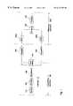
- FIG. 2illustrates a transmission receiving system in accordance with the preferred embodiment of the present invention.
- the transmitting apparatuscomprises, as already described in FIG. 1, the bitstream source 110 , the encoder 120 generally termed as forward error correction, the partitioner 130 and transmitting means comprising a first satellite 140 a , a second satellite 140 b and a delay stage 140 c.
- the receiving apparatuscomprises the channel decoder 220 , the combiner 230 and the receiving means (Rx) comprising the first and second receivers 240 a , 240 b and a delay stage 240 c .
- the transmitting apparatus and the receiving apparatusare “connected” by the first channel 300 and the second channel 400 .
- time diversityis implemented in the transmission receiving system shown in FIG. 2 .
- space diversity or spatial diversityis implemented into the inventive transmission receiving system.
- the encoder 120 in the transmitting apparatusis implemented as a convolutional encoder in accordance with the present invention.
- the convolutional encodercomprises three generator polynominals, i.e., a first generator polynominal g1 121 , a second generator polynominal g2 122 and a third generator polynominal g3 123 .
- the convolutional encoder 120has a code rate of 1/3, since, for one input bit, the encoder produces three output bits.
- the 3further comprises a puncturing unit 125 that reduces the number of bits, i.e., the number of output bits, such that an even number of output bits to be transmitted over the first and second channel is obtained.
- the puncturing unit 125is connected to the partitioner 130 , that, in accordance with the preferred embodiments of the present invention, comprises a parallel-to-serial converter and a demultiplexer to demultiplex the serial bitstream produced by the parallel-to-serial converter into two bitstreams.
- the block diagram in FIG. 3further comprises the delay stage 140 c of the transmitting means. The first transmitter and the second transmitter are not shown in FIG. 3 .
- the first portion of output bitsis transmitted via the first channel, whereas the second portion of output bits is delayed by the delay stage, transmitted via the second channel.
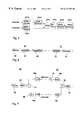
- the convolutional encoder 120With reference to FIG. 4, the functionality of the convolutional encoder 120 , the puncturing unit 125 and the partitioner 130 will be described.
- FIG. 4an input bit sequence having bits 401 , 402 and 403 is illustrated.
- the convolutional encoder 120will produce three parallel arranged output bits 411 , 412 and 413 for each input bit 401 , 402 and 403 .
- the notation of the output bits 411 to 413relates to the channel, over which the respective bit is transmitted.
- bits termed Eare transmitted over the early satellite, i.e., satellite 140 a (FIG. 2 )
- the bits termed Lare transmitted over the late satellite, i.e., the satellite 140 b (FIG.
- the output of the puncturing unit 125is fed into a parallel-to-serial converter included in the combiner 130 (FIG. 3) such that a serial bitstream, i.e., the second number of output bits, is obtained.
- the demultiplexer included in the partitioner 130demultiplexes the serial bitstream output by the parallel-to-serial converter into two bitstreams, in order to produce the first portion 410 and the second portion 420 of output bits.
- the number of bits in each of the first and second portions 410 and 420is larger than the first number of input bits 401 , 402 and 403 input into the convolutional encoder 120 .
- some redundancystill exists to be used by the channel decoder 220 (FIG. 2 ), when one channel is totally lost, for instance, when a mobile receiver is under a bridge.
- the first and second portion of output bitscomprise more bits than the first number of input bits, since both portions together still have a code rate of 1/2, whereas each portion of output bits 410 , 420 has a code rate of 1 when the convolutional encoder 120 has a code rate of 1/2.
- a convolutional encoder having a code rate of 3/8is described. This means that for a first number of input bits, the first number being 3 , a second number of output bits, the second number being 8 , is produced.
- the receiving meanscomprises a QPSK demodulator 240 d for receiving the first channel and a QPSK demodulator 240 e for receiving the second channel.
- the QPSK demodulators 240 d and 240 eonly have to be provided when the transmitting apparatus has performed a QPSK modulation.
- the output of the QPSK demodulatoris fed into the delay stage 240 c and then into a multiplexer 230 a .
- the output of the QPSK demodulator 240 eis directly fed into the multiplexer 230 a .
- the multiplexer 230 areceives the first portion of output bits ( 410 in FIG.
- This continuous serial bitstreamis input into a depuncturing unit 230 b for undoing the puncturing carried out by the puncturing unit 125 (FIG. 3 ).
- the depunctured bitstreami.e., the combined bitstream output by the combiner that comprises the multiplexer 230 a and the depuncturing unit 230 b
- the channel decoderthat, in accordance with the preferred embodiment of the present invention, comprises the Viterbi decoder 220 a and a Reed-Solomon decoder 220 b .
- the Reed-Solomon decoderonly has to be provided when a Reed-Solomon coding has been carried out in the transmitting apparatus.
- the transmitting apparatuscauses a concatenated forward error correction encoder having a convolutional encoder and a Reed-Solomon encoder.
- the receiving apparatushas to comprise a Viterbi decoder 220 a and a Reed-Solomon decoder 220 b . It is known in the art that convolutional encoders may create small burst errors. The Reed-Solomon encoder, however, is well suited for such burst errors.
- the inventive transmitting receiving system illustrated in FIG. 1, which makes use of an encoder having a code rate less than 1/2, and has a partitioner and a combineris compared to the transmission receiving system shown in FIG. 7 that makes use of a duplicator and a channel decision controlled switch.
- the encoders 120 (FIG. 1) and 64 (FIG. 7)comprise a convolutional encoder and a Reed-Solomon encoder. Furthermore, it is assumed that the convolutional encoder included in the redundancy adding encoder 120 of FIG. 1 implements a code rate of 3/8, whereas the convolutional encoder included in the redundancy adding encoder 64 of FIG. 7 encodes based on a code rate of 3/4. Since the transmitting apparatus shown in FIG. 7 transmits eight output bits for three input bits, i.e., the duplicator effectively doubles the output bits to be transmitted, it can be regarded as a redundancy adding encoder having a code rate of 3/8. The signals transmitted over the first and the second channels, however, are identical and identically derived from the bitstream output by the bitstream source 62 .
- E b /N othe ratio of the energy per useful bit rate (unit factor: W/sec) to noise power density (unit facor: W/sec).
- the “unit factor” of E b /N ois 1.
- Ris the code rate.
- C/Nrepresents the “link margin”. If the real C/N is higher than the link margin, a useful communication link is obtained. If the real C/N is lower than the C/N defined by the above-outlined equation, no satisfying communication link can be established.
- the following Tablegives the C/N in dB for three different code rates.
- the first line of the Tablerelates to the system shown in FIG. 7, whereas the third line of the Table relates to the inventive system shown in FIG. 1 .
- the factor (223/255)relates to the Reed-Solomon encoder.
- the factors 3/4, 1/2 and 3/8relate to the convolutional coders “Rate”.
- the required C/N valuealso applies to a system where the bitstream is de-multiplexed to two streams and transmitted using two QPSK modulators.
- the overall transmitted poweris defined as:
- the noise poweris defined as follows:
- NN 1 +N 2 .
- the method in accordance with the present inventioncan give a gain of 4.3 dB compared to the required C/N, if one signal is decoded only (system of FIG. 7 ). It is assumed that for other scenarios, i.e., both channels show different fading characteristics, the gain is lower. At least for the scenario C Sat1 /N or C Sat2 /N being greater than 4.9 dB, no gain is required. The output signal is error free in any case.
- the overall gain of the inventive transmission receiving systemdepends on the probability of the scenario. In other words, it is possible to receive the signal down to a C/N of 0.6 dB, which is a theoretical value that does not include implementation loss. If only one satellite signal is available, the required C/N o is equal to 67 dBHz (not including implementation loss).
- the unit factor dBHzrepresents power divided by power density in logarithmical terms.
- a convolutional encoder with a code rate of 1/3is preferred
- the output of the convolutional enocoderis punctured to a code rate of 3/8 by not transmitting one channel bit out of 9.
- the output of the convolutional encoder and puncturing unitis converted into a serial form and demultiplexed.
- Four bits out of 8are transmitted over satellite 1 , i.e., the first portion of output bits.
- the other four bitsare transmitted over satellite 2 , i.e., the second portion of output bits.
- an additional time interlevercan be used.
- the polynominals g1, g2 and g3describe the shift registers and modulo-2 adders or XOR gates which generate the convolutional code having a code rate of 1/3.
- the proposed polynominalsare as follows:
- generator polynomials different from the above mentioned generator polynomials combined with certain puncturing schemesmay be used as well (see J. Bibb Cain supra). However, the above given generator polynomials work very well in connection with the puncturing scheme described herein.
- the receiver shown in FIG. 5requires one Viterbi decoder only.
- the optimal combining with respect to the signal quality of the two signalsis automatically performed by the Viterbi decoder.
- the Viterbi decoderperforms maximum likelihood decoding using the channel state information, also called “metric”. Algorithms known for Rician and Rayleigh channels can be adapted. If only one signal is available, i.e., one channel is faded totally, the input of the Viterbi decoder can be considered as a convolutional encoder having a code rate of 1/3 punctured to a code rate of 3/4.
- the equivalent puncturing schemeis:
- a Viterbi decoderimplementing a soft decision based on probabilities is used.
- the depuncturing unitinserts probabilities rather than actual bit states. Since the depuncturing unit does not have any information about the bits punctured by the puncturing unit in the transmitting apparatus, it inserts probabilities of 0.5 for the low and the high states of the bits.
- the combiner 230(FIG. 1) additionally comprises a channel estimator, that evaluates the signal to noise ratio of signals received from each channel.
- the channel estimatordetermines low signal to noise ratios, it is adapted to insert 0.5 probabilities rather than the actual probabilities derived from the channel having a low signal to noise ratio.
- the maximum likelihood decoderis not misled by signals received via a channel having a low signal to noise ratio.
- the inventive conceptcan also be applied to a transmission system comprising three or more channels.
- the code rate of the channel encoder 120(FIG. 1) is to be 1/3 or less.
- the partitionerproduces three portions of output bits rather than two portions of output bits.
- the transmitting apparatus as described in FIG. 3can be used.
- no puncturing unitis necessary and the demultiplexer multiplexes three bitstreams, one for each of the three channels.
- redundancy adding encoderscan be adapted. These redundancy adding encoders, however, have to produce two portions of output bits that are coded differently with respect to each other, such that a “real” code rate of, for example, 3/8 in contrast to a doubled 3/4 code rate can be obtained.
- the delay imposed by the different delay stagescan be set in accordance with the real environment. Normally, a delay of four seconds is regarded as appropriate. However, other delay values can be adapted. It is to be noted, however, that high delay values result in high memory capacities for the transmitter and the receiver.
Landscapes
- Engineering & Computer Science (AREA)
- Computer Networks & Wireless Communication (AREA)
- Signal Processing (AREA)
- Detection And Prevention Of Errors In Transmission (AREA)
- Error Detection And Correction (AREA)
- Radio Transmission System (AREA)
Abstract
Description
| TABLE | ||
| Code rate | ||
| (convol. + | ||
| Reed-Solomon) | Eb/NO [dB] | C/N [dB] |
| 3/4 * (223/255) = 0.66 | 3.7 | 4.9 |
| 1/2 * (223/255) = 0.44 | 2.7 | 2.1 |
| 3/8 * (223/255) = 0.33 | app. 2.4 | 0.6 |

Claims (35)
Applications Claiming Priority (1)
| Application Number | Priority Date | Filing Date | Title |
|---|---|---|---|
| PCT/EP1998/007850WO2000036783A1 (en) | 1998-12-03 | 1998-12-03 | Apparatus and method for transmitting information and apparatus and method for receiving information |
Publications (1)
| Publication Number | Publication Date |
|---|---|
| US6314289B1true US6314289B1 (en) | 2001-11-06 |
Family
ID=8167142
Family Applications (1)
| Application Number | Title | Priority Date | Filing Date |
|---|---|---|---|
| US09/202,729Expired - LifetimeUS6314289B1 (en) | 1998-12-03 | 1998-12-03 | Apparatus and method for transmitting information and apparatus and method for receiving information |
Country Status (8)
| Country | Link |
|---|---|
| US (1) | US6314289B1 (en) |
| EP (1) | EP1123597B1 (en) |
| JP (1) | JP3464981B2 (en) |
| AU (1) | AU1966699A (en) |
| DE (1) | DE69808809T2 (en) |
| ES (1) | ES2185244T3 (en) |
| PL (1) | PL192020B1 (en) |
| WO (1) | WO2000036783A1 (en) |
Cited By (77)
| Publication number | Priority date | Publication date | Assignee | Title |
|---|---|---|---|---|
| US20020122383A1 (en)* | 2000-09-01 | 2002-09-05 | Shiquan Wu | Adaptive time diversity and spatial diversity for OFDM |
| US6510317B1 (en)* | 1999-11-04 | 2003-01-21 | Xm Satellite Radio, Inc. | Satellite digital audio radio service tuner architecture for reception of satellite and terrestrial signals |
| US6535717B1 (en)* | 1998-08-31 | 2003-03-18 | Fujitsu Limited | Method, system and apparatus for transmitting, receiving, and reproducing a digital broadcast signal |
| US20030083024A1 (en)* | 2001-10-30 | 2003-05-01 | Lawrence Richenstein | Multiple channel wireless communication system |
| US20030090993A1 (en)* | 2001-09-28 | 2003-05-15 | Kazumi Sato | OFDM Transmitting and receiving apparatus |
| WO2003090398A1 (en)* | 2002-04-18 | 2003-10-30 | Ericsson Inc. | Method for multicast over wireless networks |
| US20030226089A1 (en)* | 2002-02-15 | 2003-12-04 | Digital Fountain, Inc. | System and method for reliably communicating the content of a live data stream |
| US20040014461A1 (en)* | 2000-06-23 | 2004-01-22 | Wolfgang Theimer | Method for accessing information |
| US6684367B1 (en)* | 2000-10-13 | 2004-01-27 | Agere Systems Inc. | Channel coding based on hidden puncturing for partial-band interference channels |
| US20040091061A1 (en)* | 2002-11-13 | 2004-05-13 | Wen-Chung Liu | Enhanced wireless communication system and method thereof |
| US20040157555A1 (en)* | 2001-10-30 | 2004-08-12 | Lawrence Richenstein | Multiple channel wireless communication system |
| US6836658B1 (en)* | 2000-03-03 | 2004-12-28 | Ems Technologies, Inc. | High data rate satellite communications system and method |
| US20050099938A1 (en)* | 1999-09-15 | 2005-05-12 | Lucent Technologies Inc. | Method and apparatus for multi-stream transmission with time and frequency diversity in an orthogonal frequency division multiplexing (OFDM) communication system |
| US20050140547A1 (en)* | 2002-03-22 | 2005-06-30 | Josi Rosenfeld | Method of, and apparatus for, determining position |
| US20050166120A1 (en)* | 2004-01-23 | 2005-07-28 | Eric Ojard | Convolutional coding method for multi-band communications |
| US6990317B2 (en) | 2002-05-28 | 2006-01-24 | Wireless Innovation | Interference resistant wireless sensor and control system |
| US7103325B1 (en) | 2002-04-05 | 2006-09-05 | Nortel Networks Limited | Adaptive modulation and coding |
| US20060223461A1 (en)* | 2005-03-08 | 2006-10-05 | Rajiv Laroia | Digital broadcast methods and apparatus |
| US20060251026A1 (en)* | 2005-05-09 | 2006-11-09 | Amit Kalhan | Multiple source wireless communication system and method |
| US7136346B1 (en)* | 1999-07-20 | 2006-11-14 | Koninklijke Philips Electronic, N.V. | Record carrier method and apparatus having separate formats for a stereo signal and a data signal |
| US20070053447A1 (en)* | 2003-04-03 | 2007-03-08 | The Boeing Company | Wireless RF Link for Uncompressed Transmission of HDTV Signals |
| US20070103584A1 (en)* | 2003-04-03 | 2007-05-10 | The Boeing Company | Systems and Methods for Wireless Transmission of Uncompressed HDTV Signals |
| US20070143654A1 (en)* | 2005-12-15 | 2007-06-21 | General Instrument Corporation | Method and apparatus for using long forward error correcting codes in a content distribution system |
| US7359671B2 (en) | 2001-10-30 | 2008-04-15 | Unwired Technology Llc | Multiple channel wireless communication system |
| US20080118003A1 (en)* | 2002-11-13 | 2008-05-22 | Industrial Technology Research Institute | Enhanced Wireless Communication System and Method Thereof |
| US20080205229A1 (en)* | 2007-02-26 | 2008-08-28 | Yung-Chih Li | Method of identifying optical disc |
| US20080318518A1 (en)* | 2001-10-30 | 2008-12-25 | Coutinho Roy S | Wireless audio distribution system with range based slow muting |
| US20090049360A1 (en)* | 2007-08-13 | 2009-02-19 | Broadcom Corporation | Optimal circular buffer rate matching for turbo code |
| US20090154333A1 (en)* | 2007-12-14 | 2009-06-18 | Sivaswamy Associates, Llc. | Orthogonal code division multiplex cck (ocdm-cck) method and apparatus for high data rate wireless lan |
| US20100115569A1 (en)* | 2006-10-04 | 2010-05-06 | Yasuaki Takimoto | Multimedia information receiving apparatus |
| US7986742B2 (en) | 2002-10-25 | 2011-07-26 | Qualcomm Incorporated | Pilots for MIMO communication system |
| US20110296285A1 (en)* | 2009-02-05 | 2011-12-01 | Panasonic Corporation | Wireless communication apparatus |
| US8134976B2 (en) | 2002-10-25 | 2012-03-13 | Qualcomm Incorporated | Channel calibration for a time division duplexed communication system |
| US8145179B2 (en) | 2002-10-25 | 2012-03-27 | Qualcomm Incorporated | Data detection and demodulation for wireless communication systems |
| US8169944B2 (en) | 2002-10-25 | 2012-05-01 | Qualcomm Incorporated | Random access for wireless multiple-access communication systems |
| US8194770B2 (en) | 2002-08-27 | 2012-06-05 | Qualcomm Incorporated | Coded MIMO systems with selective channel inversion applied per eigenmode |
| US8203978B2 (en) | 2002-10-25 | 2012-06-19 | Qualcomm Incorporated | Multi-mode terminal in a wireless MIMO system |
| US8208654B2 (en) | 2001-10-30 | 2012-06-26 | Unwired Technology Llc | Noise cancellation for wireless audio distribution system |
| US8208364B2 (en) | 2002-10-25 | 2012-06-26 | Qualcomm Incorporated | MIMO system with multiple spatial multiplexing modes |
| US8218609B2 (en) | 2002-10-25 | 2012-07-10 | Qualcomm Incorporated | Closed-loop rate control for a multi-channel communication system |
| USRE43741E1 (en) | 2002-10-05 | 2012-10-16 | Qualcomm Incorporated | Systematic encoding and decoding of chain reaction codes |
| US8320301B2 (en) | 2002-10-25 | 2012-11-27 | Qualcomm Incorporated | MIMO WLAN system |
| US8339935B2 (en) | 2000-09-01 | 2012-12-25 | Apple Inc. | Adaptive time diversity and spatial diversity for OFDM |
| US8358714B2 (en) | 2005-06-16 | 2013-01-22 | Qualcomm Incorporated | Coding and modulation for multiple data streams in a communication system |
| US8570988B2 (en) | 2002-10-25 | 2013-10-29 | Qualcomm Incorporated | Channel calibration for a time division duplexed communication system |
| US8806050B2 (en) | 2010-08-10 | 2014-08-12 | Qualcomm Incorporated | Manifest file updates for network streaming of coded multimedia data |
| US8855226B2 (en) | 2005-05-12 | 2014-10-07 | Qualcomm Incorporated | Rate selection with margin sharing |
| US8873365B2 (en) | 2002-10-25 | 2014-10-28 | Qualcomm Incorporated | Transmit diversity processing for a multi-antenna communication system |
| US8887020B2 (en) | 2003-10-06 | 2014-11-11 | Digital Fountain, Inc. | Error-correcting multi-stage code generator and decoder for communication systems having single transmitters or multiple transmitters |
| US8958375B2 (en) | 2011-02-11 | 2015-02-17 | Qualcomm Incorporated | Framing for an improved radio link protocol including FEC |
| US9136878B2 (en) | 2004-05-07 | 2015-09-15 | Digital Fountain, Inc. | File download and streaming system |
| US9136983B2 (en) | 2006-02-13 | 2015-09-15 | Digital Fountain, Inc. | Streaming and buffering using variable FEC overhead and protection periods |
| US9154274B2 (en) | 2002-10-25 | 2015-10-06 | Qualcomm Incorporated | OFDM communication system with multiple OFDM symbol sizes |
| US9178535B2 (en) | 2006-06-09 | 2015-11-03 | Digital Fountain, Inc. | Dynamic stream interleaving and sub-stream based delivery |
| US9191151B2 (en) | 2006-06-09 | 2015-11-17 | Qualcomm Incorporated | Enhanced block-request streaming using cooperative parallel HTTP and forward error correction |
| US9225961B2 (en) | 2010-05-13 | 2015-12-29 | Qualcomm Incorporated | Frame packing for asymmetric stereo video |
| US9237101B2 (en) | 2007-09-12 | 2016-01-12 | Digital Fountain, Inc. | Generating and communicating source identification information to enable reliable communications |
| US9236976B2 (en) | 2001-12-21 | 2016-01-12 | Digital Fountain, Inc. | Multi stage code generator and decoder for communication systems |
| US9240810B2 (en) | 2002-06-11 | 2016-01-19 | Digital Fountain, Inc. | Systems and processes for decoding chain reaction codes through inactivation |
| US9246633B2 (en) | 1998-09-23 | 2016-01-26 | Digital Fountain, Inc. | Information additive code generator and decoder for communication systems |
| US9253233B2 (en) | 2011-08-31 | 2016-02-02 | Qualcomm Incorporated | Switch signaling methods providing improved switching between representations for adaptive HTTP streaming |
| US9264069B2 (en) | 2006-05-10 | 2016-02-16 | Digital Fountain, Inc. | Code generator and decoder for communications systems operating using hybrid codes to allow for multiple efficient uses of the communications systems |
| US9270414B2 (en) | 2006-02-21 | 2016-02-23 | Digital Fountain, Inc. | Multiple-field based code generator and decoder for communications systems |
| US9270299B2 (en) | 2011-02-11 | 2016-02-23 | Qualcomm Incorporated | Encoding and decoding using elastic codes with flexible source block mapping |
| US9281847B2 (en) | 2009-02-27 | 2016-03-08 | Qualcomm Incorporated | Mobile reception of digital video broadcasting—terrestrial services |
| US9288010B2 (en) | 2009-08-19 | 2016-03-15 | Qualcomm Incorporated | Universal file delivery methods for providing unequal error protection and bundled file delivery services |
| US9294226B2 (en) | 2012-03-26 | 2016-03-22 | Qualcomm Incorporated | Universal object delivery and template-based file delivery |
| US9380096B2 (en) | 2006-06-09 | 2016-06-28 | Qualcomm Incorporated | Enhanced block-request streaming system for handling low-latency streaming |
| US9386064B2 (en) | 2006-06-09 | 2016-07-05 | Qualcomm Incorporated | Enhanced block-request streaming using URL templates and construction rules |
| US9419749B2 (en) | 2009-08-19 | 2016-08-16 | Qualcomm Incorporated | Methods and apparatus employing FEC codes with permanent inactivation of symbols for encoding and decoding processes |
| US9432433B2 (en) | 2006-06-09 | 2016-08-30 | Qualcomm Incorporated | Enhanced block-request streaming system using signaling or block creation |
| US9473269B2 (en) | 2003-12-01 | 2016-10-18 | Qualcomm Incorporated | Method and apparatus for providing an efficient control channel structure in a wireless communication system |
| US9551785B1 (en) | 1999-04-07 | 2017-01-24 | James L. Geer | Method and apparatus for the detection of objects using electromagnetic wave attenuation patterns |
| US9602802B2 (en) | 2010-07-21 | 2017-03-21 | Qualcomm Incorporated | Providing frame packing type information for video coding |
| US9843844B2 (en) | 2011-10-05 | 2017-12-12 | Qualcomm Incorporated | Network streaming of media data |
| US9917874B2 (en) | 2009-09-22 | 2018-03-13 | Qualcomm Incorporated | Enhanced block-request streaming using block partitioning or request controls for improved client-side handling |
| US10700816B2 (en)* | 2016-08-09 | 2020-06-30 | Lg Electronics Inc. | Method for performing HARQ using polar code |
Families Citing this family (7)
| Publication number | Priority date | Publication date | Assignee | Title |
|---|---|---|---|---|
| US6229824B1 (en)* | 1999-05-26 | 2001-05-08 | Xm Satellite Radio Inc. | Method and apparatus for concatenated convolutional endcoding and interleaving |
| US7058086B2 (en) | 1999-05-26 | 2006-06-06 | Xm Satellite Radio Inc. | Method and apparatus for concatenated convolutional encoding and interleaving |
| US6154452A (en) | 1999-05-26 | 2000-11-28 | Xm Satellite Radio Inc. | Method and apparatus for continuous cross-channel interleaving |
| DE10034714A1 (en)* | 2000-07-17 | 2002-02-07 | Infineon Technologies Ag | Method and device for transmitting diversity of coded information |
| DE10220892A1 (en) | 2002-05-10 | 2003-12-18 | Fraunhofer Ges Forschung | Sending device and receiving device |
| US8050312B2 (en)* | 2007-04-05 | 2011-11-01 | Delphi Technologies, Inc. | System and method for multi-source communications |
| US20120008555A1 (en)* | 2010-06-23 | 2012-01-12 | Qualcomm Incorporated | Transmit and receive processing in the presence of interference in a wireless network |
Citations (17)
| Publication number | Priority date | Publication date | Assignee | Title |
|---|---|---|---|---|
| US4881241A (en) | 1988-02-24 | 1989-11-14 | Centre National D'etudes Des Telecommunications | Method and installation for digital communication, particularly between and toward moving vehicles |
| US5103459A (en)* | 1990-06-25 | 1992-04-07 | Qualcomm Incorporated | System and method for generating signal waveforms in a cdma cellular telephone system |
| US5258987A (en)* | 1992-04-16 | 1993-11-02 | At&T Bell Laboratories | Multilevel coding using trellis-coded modulation and reed-solomon codes |
| EP0572171A1 (en) | 1992-05-29 | 1993-12-01 | AT&T Corp. | Method and apparatus for providing time diversity for multipath fading channels |
| US5319673A (en) | 1992-04-10 | 1994-06-07 | Cd Radio Inc. | Radio frequency broadcasting systems and methods using two low-cost geosynchronous satellites |
| US5485485A (en) | 1992-04-10 | 1996-01-16 | Cd Radio Inc. | Radio frequency broadcasting systems and methods using two low-cost geosynchronous satellites and hemispherical coverage antennas |
| US5581575A (en)* | 1993-11-01 | 1996-12-03 | Qualcomm Incorporated | Method and apparatus for transmission of variable rate digital data |
| US5592471A (en) | 1995-04-21 | 1997-01-07 | Cd Radio Inc. | Mobile radio receivers using time diversity to avoid service outages in multichannel broadcast transmission systems |
| US5617333A (en)* | 1993-11-29 | 1997-04-01 | Kokusai Electric Co., Ltd. | Method and apparatus for transmission of image data |
| US5657325A (en) | 1995-03-31 | 1997-08-12 | Lucent Technologies Inc. | Transmitter and method for transmitting information packets with incremental redundancy |
| US5659569A (en)* | 1990-06-25 | 1997-08-19 | Qualcomm Incorporated | Data burst randomizer |
| US5841813A (en) | 1996-09-04 | 1998-11-24 | Lucent Technologies Inc. | Digital communications system using complementary codes and amplitude modulation |
| US5896368A (en)* | 1995-05-01 | 1999-04-20 | Telefonaktiebolaget Lm Ericsson | Multi-code compressed mode DS-CDMA systems and methods |
| US5956088A (en)* | 1995-11-21 | 1999-09-21 | Imedia Corporation | Method and apparatus for modifying encoded digital video for improved channel utilization |
| US6134696A (en)* | 1998-05-28 | 2000-10-17 | Lsi Logic Corporation | Encoding and decoding rate-1/n convolutional codes and their punctured versions |
| US6144711A (en)* | 1996-08-29 | 2000-11-07 | Cisco Systems, Inc. | Spatio-temporal processing for communication |
| US6163577A (en)* | 1996-04-26 | 2000-12-19 | Telefonaktiebolaget Lm Ericsson (Publ) | Source/channel encoding mode control method and apparatus |
- 1998
- 1998-12-03USUS09/202,729patent/US6314289B1/ennot_activeExpired - Lifetime
- 1998-12-03WOPCT/EP1998/007850patent/WO2000036783A1/enactiveIP Right Grant
- 1998-12-03AUAU19666/99Apatent/AU1966699A/ennot_activeAbandoned
- 1998-12-03DEDE69808809Tpatent/DE69808809T2/ennot_activeExpired - Lifetime
- 1998-12-03JPJP2000588923Apatent/JP3464981B2/ennot_activeExpired - Lifetime
- 1998-12-03PLPL348646Apatent/PL192020B1/enunknown
- 1998-12-03ESES98964482Tpatent/ES2185244T3/ennot_activeExpired - Lifetime
- 1998-12-03EPEP98964482Apatent/EP1123597B1/ennot_activeExpired - Lifetime
Patent Citations (18)
| Publication number | Priority date | Publication date | Assignee | Title |
|---|---|---|---|---|
| US4881241A (en) | 1988-02-24 | 1989-11-14 | Centre National D'etudes Des Telecommunications | Method and installation for digital communication, particularly between and toward moving vehicles |
| US5659569A (en)* | 1990-06-25 | 1997-08-19 | Qualcomm Incorporated | Data burst randomizer |
| US5103459A (en)* | 1990-06-25 | 1992-04-07 | Qualcomm Incorporated | System and method for generating signal waveforms in a cdma cellular telephone system |
| US5103459B1 (en)* | 1990-06-25 | 1999-07-06 | Qualcomm Inc | System and method for generating signal waveforms in a cdma cellular telephone system |
| US5319673A (en) | 1992-04-10 | 1994-06-07 | Cd Radio Inc. | Radio frequency broadcasting systems and methods using two low-cost geosynchronous satellites |
| US5485485A (en) | 1992-04-10 | 1996-01-16 | Cd Radio Inc. | Radio frequency broadcasting systems and methods using two low-cost geosynchronous satellites and hemispherical coverage antennas |
| US5258987A (en)* | 1992-04-16 | 1993-11-02 | At&T Bell Laboratories | Multilevel coding using trellis-coded modulation and reed-solomon codes |
| EP0572171A1 (en) | 1992-05-29 | 1993-12-01 | AT&T Corp. | Method and apparatus for providing time diversity for multipath fading channels |
| US5581575A (en)* | 1993-11-01 | 1996-12-03 | Qualcomm Incorporated | Method and apparatus for transmission of variable rate digital data |
| US5617333A (en)* | 1993-11-29 | 1997-04-01 | Kokusai Electric Co., Ltd. | Method and apparatus for transmission of image data |
| US5657325A (en) | 1995-03-31 | 1997-08-12 | Lucent Technologies Inc. | Transmitter and method for transmitting information packets with incremental redundancy |
| US5592471A (en) | 1995-04-21 | 1997-01-07 | Cd Radio Inc. | Mobile radio receivers using time diversity to avoid service outages in multichannel broadcast transmission systems |
| US5896368A (en)* | 1995-05-01 | 1999-04-20 | Telefonaktiebolaget Lm Ericsson | Multi-code compressed mode DS-CDMA systems and methods |
| US5956088A (en)* | 1995-11-21 | 1999-09-21 | Imedia Corporation | Method and apparatus for modifying encoded digital video for improved channel utilization |
| US6163577A (en)* | 1996-04-26 | 2000-12-19 | Telefonaktiebolaget Lm Ericsson (Publ) | Source/channel encoding mode control method and apparatus |
| US6144711A (en)* | 1996-08-29 | 2000-11-07 | Cisco Systems, Inc. | Spatio-temporal processing for communication |
| US5841813A (en) | 1996-09-04 | 1998-11-24 | Lucent Technologies Inc. | Digital communications system using complementary codes and amplitude modulation |
| US6134696A (en)* | 1998-05-28 | 2000-10-17 | Lsi Logic Corporation | Encoding and decoding rate-1/n convolutional codes and their punctured versions |
Non-Patent Citations (7)
| Title |
|---|
| "Channel Coding with Multilevel/Phase Signals", Gottfried Ungerboeck, IEEE Transactions on Information Theory, vol. IT-28, No. 1, pp 55-66, Jan. 1982. |
| "Punctured Convolutional Codes of Rate (n-l)n and Simplified Maximum Likelihood Decoding" J. Bibb Cain et al, IEEE Transactions on Information Theory, vol. IT-25, No. 1, Jan. 1979. |
| Alamouti S M, A simple transmit diversity techique for wireless communications, IEEE Journal on Selected Areas in Communications, Oct. 1998, pp. 1451-1458, vol. 16 No. 8. |
| Benelli G., "Two New Coding Techniques for Diversity Communication Systems", IEEE Transactions on Communications, Sep. 1, 1990, pp. 1530-1538, vol. 38, No. 9, New York, US. |
| Brian Kroeger, "Robust Modem and Coding Techniques for FM Hybrid IBOC DAB", USA Digital Radio Home Page, www.usadr.com, pp 1-14. |
| ETS 300 401, ETS I-European Telecommunications Standards Institute Valbonne, France, Jan. 1997, pp 149-158. |
| Samir Kallel, "Complementary Punctured Convolutional (CPC) Codes and Their Applications", IEEE Transactions on Communications, vol. 43, No. 6, Jun. 1999, pp 2005-2009. |
Cited By (147)
| Publication number | Priority date | Publication date | Assignee | Title |
|---|---|---|---|---|
| US6535717B1 (en)* | 1998-08-31 | 2003-03-18 | Fujitsu Limited | Method, system and apparatus for transmitting, receiving, and reproducing a digital broadcast signal |
| US9246633B2 (en) | 1998-09-23 | 2016-01-26 | Digital Fountain, Inc. | Information additive code generator and decoder for communication systems |
| US9551785B1 (en) | 1999-04-07 | 2017-01-24 | James L. Geer | Method and apparatus for the detection of objects using electromagnetic wave attenuation patterns |
| US7136346B1 (en)* | 1999-07-20 | 2006-11-14 | Koninklijke Philips Electronic, N.V. | Record carrier method and apparatus having separate formats for a stereo signal and a data signal |
| US20070127333A1 (en)* | 1999-07-20 | 2007-06-07 | Koninklijke Philips Electronics, N.V. | Record carrier method and apparatus having separate formats for a stereo signal and a data signal |
| US7974255B2 (en)* | 1999-09-15 | 2011-07-05 | Alcatel-Lucent Usa Inc. | Method and apparatus for multi-stream transmission with time and frequency diversity in an orthogonal frequency division multiplexing (OFDM) communication system |
| US20050099938A1 (en)* | 1999-09-15 | 2005-05-12 | Lucent Technologies Inc. | Method and apparatus for multi-stream transmission with time and frequency diversity in an orthogonal frequency division multiplexing (OFDM) communication system |
| US6510317B1 (en)* | 1999-11-04 | 2003-01-21 | Xm Satellite Radio, Inc. | Satellite digital audio radio service tuner architecture for reception of satellite and terrestrial signals |
| US6836658B1 (en)* | 2000-03-03 | 2004-12-28 | Ems Technologies, Inc. | High data rate satellite communications system and method |
| US7616925B2 (en)* | 2000-06-20 | 2009-11-10 | Nokia Corporation | Method for accessing information |
| US20040014461A1 (en)* | 2000-06-23 | 2004-01-22 | Wolfgang Theimer | Method for accessing information |
| US7801019B2 (en) | 2000-09-01 | 2010-09-21 | Nortel Networks Limited | Adaptive time diversity and spatial diversity for OFDM |
| US8077599B2 (en) | 2000-09-01 | 2011-12-13 | Nortel Networks Limited | Adaptive time diversity and spatial diversity for OFDM |
| US10404515B2 (en)* | 2000-09-01 | 2019-09-03 | Apple Inc. | Adaptive time diversity and spatial diversity for OFDM |
| US20020122383A1 (en)* | 2000-09-01 | 2002-09-05 | Shiquan Wu | Adaptive time diversity and spatial diversity for OFDM |
| US20080002568A1 (en)* | 2000-09-01 | 2008-01-03 | Nortel Networks Limited | Adaptive time diversity and spatial diversity for OFDM |
| US6985434B2 (en)* | 2000-09-01 | 2006-01-10 | Nortel Networks Limited | Adaptive time diversity and spatial diversity for OFDM |
| US9344316B2 (en)* | 2000-09-01 | 2016-05-17 | Apple Inc. | Adaptive time diversity and spatial diversity for OFDM |
| US20110044394A1 (en)* | 2000-09-01 | 2011-02-24 | Nortel Networks Limited | Adaptive time diversity and spatial diversity for OFDM |
| US20140376601A1 (en)* | 2000-09-01 | 2014-12-25 | Apple Inc. | Adaptive Time Diversity And Spatial Diversity For OFDM |
| US8837272B2 (en) | 2000-09-01 | 2014-09-16 | Apple Inc. | Adaptive time diversity and spatial diversity for OFDM |
| US20070036069A1 (en)* | 2000-09-01 | 2007-02-15 | Shiquan Wu | Adaptive time diversity and spatial diversity for OFDM |
| US9780987B2 (en)* | 2000-09-01 | 2017-10-03 | Apple Inc. | Adaptive time diversity and spatial diversity for OFDM |
| US8339935B2 (en) | 2000-09-01 | 2012-12-25 | Apple Inc. | Adaptive time diversity and spatial diversity for OFDM |
| US7688710B2 (en) | 2000-09-01 | 2010-03-30 | Nortel Networks Limited | Adaptive time diversity and spatial diversity for OFDM |
| US6684367B1 (en)* | 2000-10-13 | 2004-01-27 | Agere Systems Inc. | Channel coding based on hidden puncturing for partial-band interference channels |
| US20070297321A1 (en)* | 2001-09-28 | 2007-12-27 | Kazumi Sato | Ofdm transmitting and receiving apparatus |
| US7280504B2 (en)* | 2001-09-28 | 2007-10-09 | Kabushiki Kaisha Toshiba | OFDM transmitting and receiving apparatus |
| US20030090993A1 (en)* | 2001-09-28 | 2003-05-15 | Kazumi Sato | OFDM Transmitting and receiving apparatus |
| US7603080B2 (en) | 2001-10-30 | 2009-10-13 | Lawrence Richenstein | Multiple channel wireless communication system |
| US6987947B2 (en)* | 2001-10-30 | 2006-01-17 | Unwired Technology Llc | Multiple channel wireless communication system |
| US20060287745A1 (en)* | 2001-10-30 | 2006-12-21 | Unwired Technology Llc | Wireless speakers |
| US7076204B2 (en)* | 2001-10-30 | 2006-07-11 | Unwired Technology Llc | Multiple channel wireless communication system |
| US7937118B2 (en)* | 2001-10-30 | 2011-05-03 | Unwired Technology Llc | Wireless audio distribution system with range based slow muting |
| US8208654B2 (en) | 2001-10-30 | 2012-06-26 | Unwired Technology Llc | Noise cancellation for wireless audio distribution system |
| US20030083024A1 (en)* | 2001-10-30 | 2003-05-01 | Lawrence Richenstein | Multiple channel wireless communication system |
| US7359671B2 (en) | 2001-10-30 | 2008-04-15 | Unwired Technology Llc | Multiple channel wireless communication system |
| US20040157555A1 (en)* | 2001-10-30 | 2004-08-12 | Lawrence Richenstein | Multiple channel wireless communication system |
| US8290173B2 (en) | 2001-10-30 | 2012-10-16 | Unwired Technology Llc | Wireless speakers |
| US20080215777A1 (en)* | 2001-10-30 | 2008-09-04 | Unwired Technology Llc | Multiple channel wireless communication system |
| US20080318518A1 (en)* | 2001-10-30 | 2008-12-25 | Coutinho Roy S | Wireless audio distribution system with range based slow muting |
| US9236976B2 (en) | 2001-12-21 | 2016-01-12 | Digital Fountain, Inc. | Multi stage code generator and decoder for communication systems |
| US7249291B2 (en)* | 2002-02-15 | 2007-07-24 | Digital Fountain, Inc. | System and method for reliably communicating the content of a live data stream |
| US20030226089A1 (en)* | 2002-02-15 | 2003-12-04 | Digital Fountain, Inc. | System and method for reliably communicating the content of a live data stream |
| US20050140547A1 (en)* | 2002-03-22 | 2005-06-30 | Josi Rosenfeld | Method of, and apparatus for, determining position |
| US7103325B1 (en) | 2002-04-05 | 2006-09-05 | Nortel Networks Limited | Adaptive modulation and coding |
| WO2003090398A1 (en)* | 2002-04-18 | 2003-10-30 | Ericsson Inc. | Method for multicast over wireless networks |
| US6677864B2 (en) | 2002-04-18 | 2004-01-13 | Telefonaktiebolaget L.M. Ericsson | Method for multicast over wireless networks |
| US6990317B2 (en) | 2002-05-28 | 2006-01-24 | Wireless Innovation | Interference resistant wireless sensor and control system |
| US9240810B2 (en) | 2002-06-11 | 2016-01-19 | Digital Fountain, Inc. | Systems and processes for decoding chain reaction codes through inactivation |
| US8194770B2 (en) | 2002-08-27 | 2012-06-05 | Qualcomm Incorporated | Coded MIMO systems with selective channel inversion applied per eigenmode |
| USRE43741E1 (en) | 2002-10-05 | 2012-10-16 | Qualcomm Incorporated | Systematic encoding and decoding of chain reaction codes |
| US9236885B2 (en) | 2002-10-05 | 2016-01-12 | Digital Fountain, Inc. | Systematic encoding and decoding of chain reaction codes |
| US8873365B2 (en) | 2002-10-25 | 2014-10-28 | Qualcomm Incorporated | Transmit diversity processing for a multi-antenna communication system |
| US8170513B2 (en) | 2002-10-25 | 2012-05-01 | Qualcomm Incorporated | Data detection and demodulation for wireless communication systems |
| US9240871B2 (en) | 2002-10-25 | 2016-01-19 | Qualcomm Incorporated | MIMO WLAN system |
| US9312935B2 (en) | 2002-10-25 | 2016-04-12 | Qualcomm Incorporated | Pilots for MIMO communication systems |
| US9967005B2 (en) | 2002-10-25 | 2018-05-08 | Qualcomm Incorporated | Pilots for MIMO communication systems |
| US7986742B2 (en) | 2002-10-25 | 2011-07-26 | Qualcomm Incorporated | Pilots for MIMO communication system |
| US8462643B2 (en) | 2002-10-25 | 2013-06-11 | Qualcomm Incorporated | MIMO WLAN system |
| US8750151B2 (en) | 2002-10-25 | 2014-06-10 | Qualcomm Incorporated | Channel calibration for a time division duplexed communication system |
| US8711763B2 (en) | 2002-10-25 | 2014-04-29 | Qualcomm Incorporated | Random access for wireless multiple-access communication systems |
| US8913529B2 (en) | 2002-10-25 | 2014-12-16 | Qualcomm Incorporated | MIMO WLAN system |
| US8570988B2 (en) | 2002-10-25 | 2013-10-29 | Qualcomm Incorporated | Channel calibration for a time division duplexed communication system |
| US8134976B2 (en) | 2002-10-25 | 2012-03-13 | Qualcomm Incorporated | Channel calibration for a time division duplexed communication system |
| US8145179B2 (en) | 2002-10-25 | 2012-03-27 | Qualcomm Incorporated | Data detection and demodulation for wireless communication systems |
| US9031097B2 (en) | 2002-10-25 | 2015-05-12 | Qualcomm Incorporated | MIMO system with multiple spatial multiplexing modes |
| US8169944B2 (en) | 2002-10-25 | 2012-05-01 | Qualcomm Incorporated | Random access for wireless multiple-access communication systems |
| US8934329B2 (en) | 2002-10-25 | 2015-01-13 | Qualcomm Incorporated | Transmit diversity processing for a multi-antenna communication system |
| US8203978B2 (en) | 2002-10-25 | 2012-06-19 | Qualcomm Incorporated | Multi-mode terminal in a wireless MIMO system |
| US10382106B2 (en) | 2002-10-25 | 2019-08-13 | Qualcomm Incorporated | Pilots for MIMO communication systems |
| US8208364B2 (en) | 2002-10-25 | 2012-06-26 | Qualcomm Incorporated | MIMO system with multiple spatial multiplexing modes |
| US8218609B2 (en) | 2002-10-25 | 2012-07-10 | Qualcomm Incorporated | Closed-loop rate control for a multi-channel communication system |
| US9013974B2 (en) | 2002-10-25 | 2015-04-21 | Qualcomm Incorporated | MIMO WLAN system |
| US9154274B2 (en) | 2002-10-25 | 2015-10-06 | Qualcomm Incorporated | OFDM communication system with multiple OFDM symbol sizes |
| US8320301B2 (en) | 2002-10-25 | 2012-11-27 | Qualcomm Incorporated | MIMO WLAN system |
| US9048892B2 (en) | 2002-10-25 | 2015-06-02 | Qualcomm Incorporated | MIMO system with multiple spatial multiplexing modes |
| US8355313B2 (en) | 2002-10-25 | 2013-01-15 | Qualcomm Incorporated | MIMO system with multiple spatial multiplexing modes |
| US8483188B2 (en) | 2002-10-25 | 2013-07-09 | Qualcomm Incorporated | MIMO system with multiple spatial multiplexing modes |
| US7356093B2 (en)* | 2002-11-13 | 2008-04-08 | Wen-Chung Liu | Enhanced wireless communication system and method thereof |
| US20080118003A1 (en)* | 2002-11-13 | 2008-05-22 | Industrial Technology Research Institute | Enhanced Wireless Communication System and Method Thereof |
| US20040091061A1 (en)* | 2002-11-13 | 2004-05-13 | Wen-Chung Liu | Enhanced wireless communication system and method thereof |
| US7535965B2 (en) | 2003-04-03 | 2009-05-19 | The Boeing Company | Systems and methods for wireless transmission of uncompressed HDTV signals |
| US7542511B2 (en)* | 2003-04-03 | 2009-06-02 | The Boeing Company | Wireless RF link for uncompressed transmission of HDTV signals |
| US20070053447A1 (en)* | 2003-04-03 | 2007-03-08 | The Boeing Company | Wireless RF Link for Uncompressed Transmission of HDTV Signals |
| US20070103584A1 (en)* | 2003-04-03 | 2007-05-10 | The Boeing Company | Systems and Methods for Wireless Transmission of Uncompressed HDTV Signals |
| US8887020B2 (en) | 2003-10-06 | 2014-11-11 | Digital Fountain, Inc. | Error-correcting multi-stage code generator and decoder for communication systems having single transmitters or multiple transmitters |
| US10742358B2 (en) | 2003-12-01 | 2020-08-11 | Qualcomm Incorporated | Method and apparatus for providing an efficient control channel structure in a wireless communication system |
| US9876609B2 (en) | 2003-12-01 | 2018-01-23 | Qualcomm Incorporated | Method and apparatus for providing an efficient control channel structure in a wireless communication system |
| US9473269B2 (en) | 2003-12-01 | 2016-10-18 | Qualcomm Incorporated | Method and apparatus for providing an efficient control channel structure in a wireless communication system |
| US20050166120A1 (en)* | 2004-01-23 | 2005-07-28 | Eric Ojard | Convolutional coding method for multi-band communications |
| US7853859B2 (en)* | 2004-01-23 | 2010-12-14 | Broadcom Corporation | Convolutional coding method for multi-band communications |
| US9236887B2 (en) | 2004-05-07 | 2016-01-12 | Digital Fountain, Inc. | File download and streaming system |
| US9136878B2 (en) | 2004-05-07 | 2015-09-15 | Digital Fountain, Inc. | File download and streaming system |
| US20060223461A1 (en)* | 2005-03-08 | 2006-10-05 | Rajiv Laroia | Digital broadcast methods and apparatus |
| US8363592B2 (en) | 2005-03-08 | 2013-01-29 | Qualcomm Incorporated | Digital broadcast methods and apparatus |
| US20060223520A1 (en)* | 2005-03-08 | 2006-10-05 | Rajiv Laroia | Methods and apparatus for efficient digital broadcast signaling in a wireless communications system |
| US7990840B2 (en)* | 2005-03-08 | 2011-08-02 | Qualcomm Incorporated | Methods and apparatus for efficient digital broadcast signaling in a wireless communications system |
| US20060251026A1 (en)* | 2005-05-09 | 2006-11-09 | Amit Kalhan | Multiple source wireless communication system and method |
| US7515565B2 (en)* | 2005-05-09 | 2009-04-07 | Kyocera Corporation | Multiple source wireless communication system and method |
| US8855226B2 (en) | 2005-05-12 | 2014-10-07 | Qualcomm Incorporated | Rate selection with margin sharing |
| US8358714B2 (en) | 2005-06-16 | 2013-01-22 | Qualcomm Incorporated | Coding and modulation for multiple data streams in a communication system |
| US20070143654A1 (en)* | 2005-12-15 | 2007-06-21 | General Instrument Corporation | Method and apparatus for using long forward error correcting codes in a content distribution system |
| US7831887B2 (en)* | 2005-12-15 | 2010-11-09 | General Instrument Corporation | Method and apparatus for using long forward error correcting codes in a content distribution system |
| US9136983B2 (en) | 2006-02-13 | 2015-09-15 | Digital Fountain, Inc. | Streaming and buffering using variable FEC overhead and protection periods |
| US9270414B2 (en) | 2006-02-21 | 2016-02-23 | Digital Fountain, Inc. | Multiple-field based code generator and decoder for communications systems |
| US9264069B2 (en) | 2006-05-10 | 2016-02-16 | Digital Fountain, Inc. | Code generator and decoder for communications systems operating using hybrid codes to allow for multiple efficient uses of the communications systems |
| US9178535B2 (en) | 2006-06-09 | 2015-11-03 | Digital Fountain, Inc. | Dynamic stream interleaving and sub-stream based delivery |
| US9432433B2 (en) | 2006-06-09 | 2016-08-30 | Qualcomm Incorporated | Enhanced block-request streaming system using signaling or block creation |
| US9191151B2 (en) | 2006-06-09 | 2015-11-17 | Qualcomm Incorporated | Enhanced block-request streaming using cooperative parallel HTTP and forward error correction |
| US9386064B2 (en) | 2006-06-09 | 2016-07-05 | Qualcomm Incorporated | Enhanced block-request streaming using URL templates and construction rules |
| US11477253B2 (en) | 2006-06-09 | 2022-10-18 | Qualcomm Incorporated | Enhanced block-request streaming system using signaling or block creation |
| US9209934B2 (en) | 2006-06-09 | 2015-12-08 | Qualcomm Incorporated | Enhanced block-request streaming using cooperative parallel HTTP and forward error correction |
| US9380096B2 (en) | 2006-06-09 | 2016-06-28 | Qualcomm Incorporated | Enhanced block-request streaming system for handling low-latency streaming |
| US8726318B2 (en)* | 2006-10-04 | 2014-05-13 | Mitsubishi Electric Corporation | Multimedia information receiving apparatus |
| US20100115569A1 (en)* | 2006-10-04 | 2010-05-06 | Yasuaki Takimoto | Multimedia information receiving apparatus |
| US20080205229A1 (en)* | 2007-02-26 | 2008-08-28 | Yung-Chih Li | Method of identifying optical disc |
| US20090049360A1 (en)* | 2007-08-13 | 2009-02-19 | Broadcom Corporation | Optimal circular buffer rate matching for turbo code |
| US8069400B2 (en)* | 2007-08-13 | 2011-11-29 | Broadcom Corporation | Optimal circular buffer rate matching for turbo code |
| US9237101B2 (en) | 2007-09-12 | 2016-01-12 | Digital Fountain, Inc. | Generating and communicating source identification information to enable reliable communications |
| US20110007626A1 (en)* | 2007-12-14 | 2011-01-13 | Sivaswamy Associates, Llc. | Orthogonal code division multiplex cck (ocdm-cck) method and apparatus for high data rate wireless lan |
| US7817708B2 (en) | 2007-12-14 | 2010-10-19 | Sivaswamy Associates, Llc. | Orthogonal code division multiplex CCK (OCDM-CCK) method and apparatus for high data rate wireless LAN |
| US8130814B2 (en) | 2007-12-14 | 2012-03-06 | Ram Sivaswamy | Orthogonal code division multiplex CCK (OCDM-CCK) method and apparatus for high data rate wireless LAN |
| US20090154333A1 (en)* | 2007-12-14 | 2009-06-18 | Sivaswamy Associates, Llc. | Orthogonal code division multiplex cck (ocdm-cck) method and apparatus for high data rate wireless lan |
| US8880982B2 (en)* | 2009-02-05 | 2014-11-04 | Panasonic Corporation | Wireless communication apparatus |
| US20110296285A1 (en)* | 2009-02-05 | 2011-12-01 | Panasonic Corporation | Wireless communication apparatus |
| US9281847B2 (en) | 2009-02-27 | 2016-03-08 | Qualcomm Incorporated | Mobile reception of digital video broadcasting—terrestrial services |
| US9419749B2 (en) | 2009-08-19 | 2016-08-16 | Qualcomm Incorporated | Methods and apparatus employing FEC codes with permanent inactivation of symbols for encoding and decoding processes |
| US9660763B2 (en) | 2009-08-19 | 2017-05-23 | Qualcomm Incorporated | Methods and apparatus employing FEC codes with permanent inactivation of symbols for encoding and decoding processes |
| US9288010B2 (en) | 2009-08-19 | 2016-03-15 | Qualcomm Incorporated | Universal file delivery methods for providing unequal error protection and bundled file delivery services |
| US9876607B2 (en) | 2009-08-19 | 2018-01-23 | Qualcomm Incorporated | Methods and apparatus employing FEC codes with permanent inactivation of symbols for encoding and decoding processes |
| US11770432B2 (en) | 2009-09-22 | 2023-09-26 | Qualcomm Incorporated | Enhanced block-request streaming system for handling low-latency streaming |
| US12155715B2 (en) | 2009-09-22 | 2024-11-26 | Qualcomm Incorporated | Enhanced block-request streaming using block partitioning or request controls for improved client-side handling |
| US9917874B2 (en) | 2009-09-22 | 2018-03-13 | Qualcomm Incorporated | Enhanced block-request streaming using block partitioning or request controls for improved client-side handling |
| US10855736B2 (en) | 2009-09-22 | 2020-12-01 | Qualcomm Incorporated | Enhanced block-request streaming using block partitioning or request controls for improved client-side handling |
| US11743317B2 (en) | 2009-09-22 | 2023-08-29 | Qualcomm Incorporated | Enhanced block-request streaming using block partitioning or request controls for improved client-side handling |
| US9225961B2 (en) | 2010-05-13 | 2015-12-29 | Qualcomm Incorporated | Frame packing for asymmetric stereo video |
| US9602802B2 (en) | 2010-07-21 | 2017-03-21 | Qualcomm Incorporated | Providing frame packing type information for video coding |
| US9456015B2 (en) | 2010-08-10 | 2016-09-27 | Qualcomm Incorporated | Representation groups for network streaming of coded multimedia data |
| US8806050B2 (en) | 2010-08-10 | 2014-08-12 | Qualcomm Incorporated | Manifest file updates for network streaming of coded multimedia data |
| US9319448B2 (en) | 2010-08-10 | 2016-04-19 | Qualcomm Incorporated | Trick modes for network streaming of coded multimedia data |
| US8958375B2 (en) | 2011-02-11 | 2015-02-17 | Qualcomm Incorporated | Framing for an improved radio link protocol including FEC |
| US9270299B2 (en) | 2011-02-11 | 2016-02-23 | Qualcomm Incorporated | Encoding and decoding using elastic codes with flexible source block mapping |
| US9253233B2 (en) | 2011-08-31 | 2016-02-02 | Qualcomm Incorporated | Switch signaling methods providing improved switching between representations for adaptive HTTP streaming |
| US9843844B2 (en) | 2011-10-05 | 2017-12-12 | Qualcomm Incorporated | Network streaming of media data |
| US9294226B2 (en) | 2012-03-26 | 2016-03-22 | Qualcomm Incorporated | Universal object delivery and template-based file delivery |
| US10700816B2 (en)* | 2016-08-09 | 2020-06-30 | Lg Electronics Inc. | Method for performing HARQ using polar code |
Also Published As
| Publication number | Publication date |
|---|---|
| WO2000036783A1 (en) | 2000-06-22 |
| PL348646A1 (en) | 2002-06-03 |
| DE69808809D1 (en) | 2002-11-21 |
| PL192020B1 (en) | 2006-08-31 |
| EP1123597B1 (en) | 2002-10-16 |
| AU1966699A (en) | 2000-07-03 |
| JP2002533014A (en) | 2002-10-02 |
| ES2185244T3 (en) | 2003-04-16 |
| EP1123597A1 (en) | 2001-08-16 |
| JP3464981B2 (en) | 2003-11-10 |
| DE69808809T2 (en) | 2003-06-18 |
Similar Documents
| Publication | Publication Date | Title |
|---|---|---|
| US6314289B1 (en) | Apparatus and method for transmitting information and apparatus and method for receiving information | |
| JP4557430B2 (en) | Digital broadcasting system and method | |
| US6704370B1 (en) | Interleaving methodology and apparatus for CDMA | |
| US7653088B2 (en) | Method for concatenated convolutional encoding and interleaving | |
| US6192038B1 (en) | Method and apparatus for wireless communication employing aggregation for digital signals | |
| JP3671149B2 (en) | Communication system handoff operation combining turbo coding and soft handoff technology | |
| US7436895B1 (en) | Concatenated space-time coding | |
| USRE41498E1 (en) | Device and methods for channel coding and rate matching in a communication system | |
| US20030012315A1 (en) | System and method for multistage error correction coding wirelessly transmitted information in a multiple antennae communication system | |
| US7356090B2 (en) | Transmission/reception apparatus for a wireless communication system with three transmission antennas | |
| KR20030010402A (en) | Method for transmitting/receiving using plurality of antennas, system for the same | |
| US6917629B1 (en) | Rate detection in radio communication systems | |
| US6876641B2 (en) | Fast feedback channel with flexible bit reliability for wireless communications | |
| EP1441462B1 (en) | Apparatus and method for transmitting and receiving data in a mobile communication system using punctured space-time trellis codes | |
| Biglieri et al. | Coding for the fading channel: a survey | |
| US6654928B1 (en) | Hybrid dimensional, spherical space-time coding and decoding apparatus, and associated method, for a communication system | |
| EP3695534B1 (en) | Signal overlay design and detection for satellite communication channels | |
| CN1291385A (en) | Digital broodcast system using satellite direct broadcast and terrestrial repeater | |
| US20030081696A1 (en) | System and method for estimating signal to noise ratio | |
| JP2001251199A (en) | Transmission device, communication system and communication method | |
| Hirata et al. | A digital transmission system for global maritime satellite communications | |
| EP1199828A2 (en) | High efficiency signaling with selective coding and interleaving | |
| Martin et al. | Statistical analysis and optimal design for efficient mobile satellite broadcast with diversity | |
| Tsie et al. | Performance of concatenated trellis-coded 16QAM with pilot symbol aided technique in the presence of fading | |
| KR20020004068A (en) | Space-time trellis code construction method for wireless communications |
Legal Events
| Date | Code | Title | Description |
|---|---|---|---|
| AS | Assignment | Owner name:FRAUNHOFER-GESELLSCHAFT ZUR FORDERUNG DER ANGEWAND Free format text:ASSIGNMENT OF ASSIGNORS INTEREST;ASSIGNORS:EBERLEIN, ERNEST;BREILING, MARCO;STOESSEL, JAN;AND OTHERS;REEL/FRAME:009957/0653 Effective date:19981214 | |
| AS | Assignment | Owner name:FRAUNHOFER-GESELLSCHAFT ZUR FORDERUNG DER ANGEWAND Free format text:ASSIGNMENT OF ASSIGNORS INTEREST;ASSIGNORS:EBERLEIN, ERNST;BREILING, MARCO;STOESSEL, JAN;AND OTHERS;REEL/FRAME:011010/0961 Effective date:19981214 | |
| STCF | Information on status: patent grant | Free format text:PATENTED CASE | |
| FEPP | Fee payment procedure | Free format text:PAYOR NUMBER ASSIGNED (ORIGINAL EVENT CODE: ASPN); ENTITY STATUS OF PATENT OWNER: LARGE ENTITY | |
| FPAY | Fee payment | Year of fee payment:4 | |
| FPAY | Fee payment | Year of fee payment:8 | |
| FPAY | Fee payment | Year of fee payment:12 | |
| IPR | Aia trial proceeding filed before the patent and appeal board: inter partes review | Free format text:TRIAL NO: IPR2018-00690 Opponent name:SIRIUS XM RADIO INC. Effective date:20180223 | |
| IPRC | Trial and appeal board: inter partes review certificate | Kind code of ref document:K1 Free format text:INTER PARTES REVIEW CERTIFICATE; TRIAL NO. IPR2018-00690, FEB. 23, 2018 INTER PARTES REVIEW CERTIFICATE FOR PATENT 6,314,289, ISSUED NOV. 6, 2001, APPL. NO. 09/202,729, MAY 17, 1999 INTER PARTES REVIEW CERTIFICATE ISSUED JUN. 3, 2022 Effective date:20220603 |