US6314093B1 - Traffic route finder in communications network - Google Patents
Traffic route finder in communications networkDownload PDFInfo
- Publication number
- US6314093B1 US6314093B1US09/088,805US8880598AUS6314093B1US 6314093 B1US6314093 B1US 6314093B1US 8880598 AUS8880598 AUS 8880598AUS 6314093 B1US6314093 B1US 6314093B1
- Authority
- US
- United States
- Prior art keywords
- data
- network
- routes
- route
- node
- Prior art date
- Legal status (The legal status is an assumption and is not a legal conclusion. Google has not performed a legal analysis and makes no representation as to the accuracy of the status listed.)
- Expired - Lifetime
Links
- 238000004891communicationMethods0.000titleabstractdescription36
- 238000000034methodMethods0.000claimsabstractdescription104
- 230000002068genetic effectEffects0.000claimsabstractdescription29
- 230000008569processEffects0.000claimsdescription54
- 230000035772mutationEffects0.000claimsdescription10
- 238000009826distributionMethods0.000claimsdescription9
- 238000003491arrayMethods0.000abstractdescription2
- 238000007726management methodMethods0.000description32
- 238000011156evaluationMethods0.000description29
- 230000006870functionEffects0.000description25
- 238000012854evaluation processMethods0.000description14
- 238000012545processingMethods0.000description14
- 230000007246mechanismEffects0.000description10
- 238000010353genetic engineeringMethods0.000description9
- 230000004044responseEffects0.000description8
- 238000010586diagramMethods0.000description7
- 238000004364calculation methodMethods0.000description6
- 238000002921genetic algorithm searchMethods0.000description6
- 238000013473artificial intelligenceMethods0.000description5
- 238000007781pre-processingMethods0.000description5
- 238000002922simulated annealingMethods0.000description5
- TZCXTZWJZNENPQ-UHFFFAOYSA-Lbarium sulfateChemical compound[Ba+2].[O-]S([O-])(=O)=OTZCXTZWJZNENPQ-UHFFFAOYSA-L0.000description4
- 238000013500data storageMethods0.000description4
- 238000005259measurementMethods0.000description4
- 238000010845search algorithmMethods0.000description4
- 230000005540biological transmissionEffects0.000description3
- 238000013461designMethods0.000description3
- 238000009434installationMethods0.000description3
- 230000003993interactionEffects0.000description3
- 238000004519manufacturing processMethods0.000description3
- 230000001360synchronised effectEffects0.000description3
- 101000825071Homo sapiens Sclerostin domain-containing protein 1Proteins0.000description2
- 102100022432Sclerostin domain-containing protein 1Human genes0.000description2
- 230000002457bidirectional effectEffects0.000description2
- 230000006727cell lossEffects0.000description2
- 230000007717exclusionEffects0.000description2
- 238000002474experimental methodMethods0.000description2
- 238000013507mappingMethods0.000description2
- 238000012546transferMethods0.000description2
- 235000008694Humulus lupulusNutrition0.000description1
- 230000009286beneficial effectEffects0.000description1
- 230000008859changeEffects0.000description1
- 238000013479data entryMethods0.000description1
- 230000003247decreasing effectEffects0.000description1
- 230000000694effectsEffects0.000description1
- 238000007689inspectionMethods0.000description1
- 239000011159matrix materialSubstances0.000description1
- COCAUCFPFHUGAA-MGNBDDOMSA-Nn-[3-[(1s,7s)-5-amino-4-thia-6-azabicyclo[5.1.0]oct-5-en-7-yl]-4-fluorophenyl]-5-chloropyridine-2-carboxamideChemical compoundC=1C=C(F)C([C@@]23N=C(SCC[C@@H]2C3)N)=CC=1NC(=O)C1=CC=C(Cl)C=N1COCAUCFPFHUGAA-MGNBDDOMSA-N0.000description1
- 230000003287optical effectEffects0.000description1
- 239000013307optical fiberSubstances0.000description1
- 238000005457optimizationMethods0.000description1
- 230000002093peripheral effectEffects0.000description1
- 238000012805post-processingMethods0.000description1
- 230000007723transport mechanismEffects0.000description1
- 230000000007visual effectEffects0.000description1
- 238000005303weighingMethods0.000description1
Images


Classifications
- H—ELECTRICITY
- H04—ELECTRIC COMMUNICATION TECHNIQUE
- H04Q—SELECTING
- H04Q11/00—Selecting arrangements for multiplex systems
- H04Q11/04—Selecting arrangements for multiplex systems for time-division multiplexing
- H04Q11/0428—Integrated services digital network, i.e. systems for transmission of different types of digitised signals, e.g. speech, data, telecentral, television signals
- H04Q11/0478—Provisions for broadband connections
- H—ELECTRICITY
- H04—ELECTRIC COMMUNICATION TECHNIQUE
- H04L—TRANSMISSION OF DIGITAL INFORMATION, e.g. TELEGRAPHIC COMMUNICATION
- H04L45/00—Routing or path finding of packets in data switching networks
- H04L45/12—Shortest path evaluation
- H—ELECTRICITY
- H04—ELECTRIC COMMUNICATION TECHNIQUE
- H04L—TRANSMISSION OF DIGITAL INFORMATION, e.g. TELEGRAPHIC COMMUNICATION
- H04L45/00—Routing or path finding of packets in data switching networks
- H04L45/24—Multipath
- H—ELECTRICITY
- H04—ELECTRIC COMMUNICATION TECHNIQUE
- H04J—MULTIPLEX COMMUNICATION
- H04J2203/00—Aspects of optical multiplex systems other than those covered by H04J14/05 and H04J14/07
- H04J2203/0001—Provisions for broadband connections in integrated services digital network using frames of the Optical Transport Network [OTN] or using synchronous transfer mode [STM], e.g. SONET, SDH
- H04J2203/0051—Network Node Interface, e.g. tandem connections, transit switching
- H04J2203/0053—Routing
- H—ELECTRICITY
- H04—ELECTRIC COMMUNICATION TECHNIQUE
- H04J—MULTIPLEX COMMUNICATION
- H04J2203/00—Aspects of optical multiplex systems other than those covered by H04J14/05 and H04J14/07
- H04J2203/0001—Provisions for broadband connections in integrated services digital network using frames of the Optical Transport Network [OTN] or using synchronous transfer mode [STM], e.g. SONET, SDH
- H04J2203/0064—Admission Control
- H04J2203/0067—Resource management and allocation
- H04J2203/0069—Channel allocation
- H—ELECTRICITY
- H04—ELECTRIC COMMUNICATION TECHNIQUE
- H04L—TRANSMISSION OF DIGITAL INFORMATION, e.g. TELEGRAPHIC COMMUNICATION
- H04L12/00—Data switching networks
- H04L12/54—Store-and-forward switching systems
- H04L12/56—Packet switching systems
- H04L12/5601—Transfer mode dependent, e.g. ATM
- H04L2012/5619—Network Node Interface, e.g. tandem connections, transit switching
- H04L2012/562—Routing
- H—ELECTRICITY
- H04—ELECTRIC COMMUNICATION TECHNIQUE
- H04L—TRANSMISSION OF DIGITAL INFORMATION, e.g. TELEGRAPHIC COMMUNICATION
- H04L12/00—Data switching networks
- H04L12/54—Store-and-forward switching systems
- H04L12/56—Packet switching systems
- H04L12/5601—Transfer mode dependent, e.g. ATM
- H04L2012/5638—Services, e.g. multimedia, GOS, QOS
- H04L2012/564—Connection-oriented
- H04L2012/5642—Multicast/broadcast/point-multipoint, e.g. VOD
- H—ELECTRICITY
- H04—ELECTRIC COMMUNICATION TECHNIQUE
- H04L—TRANSMISSION OF DIGITAL INFORMATION, e.g. TELEGRAPHIC COMMUNICATION
- H04L12/00—Data switching networks
- H04L12/54—Store-and-forward switching systems
- H04L12/56—Packet switching systems
- H04L12/5601—Transfer mode dependent, e.g. ATM
- H04L2012/5638—Services, e.g. multimedia, GOS, QOS
- H04L2012/5646—Cell characteristics, e.g. loss, delay, jitter, sequence integrity
- H04L2012/5651—Priority, marking, classes
Definitions
- the present inventionrelates to a method and apparatus for finding routes for a plurality of connections in a communications network comprising a plurality of node elements connected by a plurality of link elements.
- a conventional broadband circuit switched communications networkfor example a telephony network or a mobile phone network, comprises a plurality of nodes, at which are provided node equipment, the nodes connected by a plurality of communications links, the links comprising link equipment.
- the node equipmentmay comprise, for example a telecommunications switch apparatus, and the links may comprise a terrestrial link, eg an optical fiber link or coaxial cable or a wireless link.
- An increasing range of servicesare delivered over such networks, including as examples, video on demand, video conferencing, distance learning, and internet services.
- Such servicesinvolve delivering different traffic data types, eg voice traffic, video or computer data traffic, having different characteristics, some types of traffic being more sensitive to delay than others and the different traffic types having different ranges of bitrate requirements.
- These servicesmay involve delivery of data from a single source to a single destination (point to point) from a single source to many destinations (point to multipoint) or from a plurality of sources to a plurality of destinations (multipoint to multipoint).
- Such servicesplace heavy requirements for routing of connections supporting these services over a network.
- WO 96/31969there is disclosed a method of routing traffic from a communications network which uses a genetic algorithm search routine to find optimum sets of paths between nodes in a network for routing of traffic on a point to point connection basis with the object of minimizing a number of communications channels used, and to reduce a risk of a communications system being unable to handle a high volume of traffic.
- a set of shortest pathsforms the basis for an initial string population of the genetic algorithm.
- routesare selected according to a fitness criteria which includes a user specified weighting based on a number of channels required to support traffic, utilization of links represented as a number of links whose capacity could be exceeded, and a user specified “path cost” comprising a sum of costs of a plurality of links of a path between nodes.
- the usercan vary the fitness criteria by altering the respective weighting given to the path cost, utilization, and number of channels in order to customize the genetic algorithm process to select for these criteria according to an importance as reflected in the user specified weightings.
- shortest path routingcannot deal with service requests for mixed traffic data types. Further, use of shortest path routing can lead to unbalanced use of some routes or links in a network, whilst other routes and links remain under utilized.
- Users of services delivered over a communications networkmay make service requests for connections over the network, specifying a source node and one or more destination nodes for each connection.
- Such connection requestsneed not usually specify a route of nodes and links in the network which should be taken between the source and destination nodes. Routes across the network need to be assigned to connection requests in order to implement connections.
- One object of the present inventionis to route connection requests in a communication network in a manner which takes into account a plurality of connection requests simultaneously rather than one connection request at a time.
- Another objectis to balance routing of connections across the network. For instance, if two connections would ideally include a same link in a shortest path, but this could result in either that link becoming overloaded or one of the connections needing to take a much longer route, then it may be beneficial for one or both of the connections to be routed over slightly longer routes in order to avoid network congestion, thereby resulting in a more even distribution of network link and node utilization.
- Another object of the present inventionis to provide a capability to include or exclude certain nodes or links from routes found for a particular connection, for example if it is known that a particular network node equipment is not working properly or for security reasons.
- a further objectis to provide a generic route finding means which is reusable for circuit switched communications networks using different transport protocol types.
- the generic route finder meanstakes a modularized embodiment capable of being installed in a network controller or network manager, and acting as a server for a plurality of other network management applications.
- a further object of the present inventionis to route connection requests in a communications network according to a type of traffic which is to be carried.
- a further object of the present inventionis to distribute traffic of a point to point service connection over a plurality of routes.
- a networkcomprising a plurality of nodes and links, a method of assigning a plurality of routes to a plurality of connections, each said connection having a source node and a destination node, said method comprising the steps of:
- said process of selectingfavors selection of a route comprising lightly utilized links over routes comprising heavily utilized links.
- Said methodpreferably comprises applying an artificial intelligence technique.
- the artificial intelligence techniqueis applied to select a set of routes to satisfy all connections, wherein the selection provides an optimized balancing of load across the network as a whole, or across selected parts of the network.
- an artificial intelligence techniquepreferably comprises a genetic algorithm, but may comprise simulated annealing, or a like technique.
- said methodcomprises the step of assigning a link cost at each said link of the network, wherein said process of selecting favors selection of routes having lower link costs over routes having higher link costs.
- a method of assigning a plurality of routes to a plurality of connectionscomprising the steps:
- said methodcomprises the steps of:
- bit stringsare manipulated using genetic algorithm operations, including the processes of reproduction, mutation, crossover and merging.
- said step of evaluating a total costcomprises the step of adding costs of traversing each link in said selected routes.
- said routes having minimum said total costare output.
- a plurality of routesare found for each connection to be routed and a route cost of each of said plurality of routes preferably does not exceed a connection cost of said connection to be routed.
- a communications networkcomprising a plurality of nodes linked by a plurality of links, a method of finding routes of links for a plurality of communications connections, each said connection having a source node and a destination node, said method comprising the machine executable steps of:
- a communications networkcomprising a plurality of nodes linked by a plurality of links, a method of finding routes of links for a plurality of communications connections, each said connection having a source node and a destination node, said method comprising the machine executable steps of:
- connection's source node and its destination nodeFor each said connection to be routed, selecting one of said corresponding plurality of routes between the connection's source node and its destination node;
- said methodcomprises the steps of: selecting one or more of said nodes and/or one or more said links to be included or excluded from said routes to be found for one or more of said connections to be routed.
- a network management apparatusfor a communications network, comprising a plurality of node elements and link elements, said network management apparatus comprising means for determining a plurality of routes across said communications network in response to a plurality of received service requests, said route determining means comprising:
- network data processing meansoperating to receive network data describing a layout and status of a plurality of network elements, and converting said network data to a generic graph representation representing a plurality of nodes, and a plurality of links linking said nodes;
- service request data processing meansoperating to receive a plurality of service request data, said service request data describing at least one source node and at least one destination node, said service request data processor operating to convert said service request data into a generic format;
- route data processing meansoperating to input said generic network data and said generic service request data and to assign at least one route across said generic graph representation for each said service request data, said route finding means outputting a generic routing data describing said plurality of routes.
- Said network management apparatusmay comprise constraint data storage means operating to store constraint data describing a plurality of constraints on determining said routes, wherein said route finder means determines said routes in accordance with said constraint data input from said constraint data storage means.
- route data processing meanscomprises a data processing machine comprising a processor and data storage means.
- Said route data processing meansmay comprise means for calculating a shortest paths across said network data.
- said network management apparatuscomprises an interface interfacing said route data processing means with said service request data processing means, said network data processor, and said route data processing means, said interface comprising a data file storing data in dimensionless format.
- said data filecomprises an ASCII protocol data file.
- the data filepreferably comprises a plurality of sections, said sections containing data describing parameters selected from the following set:
- Said data filepreferably comprises sections containing data describing the following parameters:
- Said data filepreferably comprises sections containing data describing the following parameters:
- the inventionincludes, in a communications network comprising a plurality of nodes linked by a plurality of links, a method of finding a plurality of routes of links for a plurality of communications connections, each said connection having a source node and a destination node pair, said method comprising the machine executable steps of:
- balancing of loading over a networkmay be achieved.
- said methodcomprises the steps of:
- said bit stringis manipulated using genetic algorithm operations, including reproduction, mutation, crossover and merging.
- Said step of evaluating a total costmay comprise the step of:
- said routes with minimum said total costare output.
- a plurality of routesare found for each said connection to be routed, said route cost of each of said plurality of routes not exceeding said connection cost of said connection to be routed.
- the apparatusmay comprise a processor and memory configured to execute a method according to the above aspects.
- the inventionincludes a communications network configured by a method according to the above aspects.
- the inventionincludes in a network comprising a plurality of nodes linked by a plurality of links, a method of finding routes of links for a plurality of communications connections, each said connection having a source node and a destination node, said method comprising the machine executable steps of:
- the inventionincludes in a communications network comprising a plurality of nodes linked by a plurality of links, a method of finding routes of links for a plurality of communications connections, each said connection having a source node and a destination node, said method comprising the machine executable steps of:
- Methods for routing of connections according to the present inventionmay have application in network design. Simulating a number of connections can identify any unnecessary links in the network, eg links which are used lightly or not at all. Important links in the network may also be identified by applying conventional routing algorithms and techniques, for example heavily loaded links or links which are potential bottlenecks.
- FIG. 1illustrates schematically a broadband communications network including a plurality of node equipment, a plurality of link equipment and a network controller;
- FIG. 2illustrates schematically an architecture of the network controller identified in FIG. 1 including a route finder component
- FIG. 3illustrates schematically a generic representation of a topology of the network shown in FIG. 1, reduced to a plurality of nodes and links;
- FIG. 4illustrates an architecture of the route finder component identified in FIG. 3, including a service request pre-processor, a network data pre-processor, a route finder engine, an evaluation function processor, a graphical user interface, a route data post processor, and data inputs and outputs associated with the route finder component;
- FIG. 5illustrates schematically interaction of the route finder engine with a network management application
- FIG. 6illustrates a data flow diagram showing schematically flows of data and data processing operations within the route finder engine
- FIG. 7illustrates schematically steps executed by the route finder component identified in FIG. 3;
- FIG. 8illustrates the generic representation of a network identified in FIG. 3 combined with elements used by the route finder
- FIG. 9illustrates the generic representation of a network identified in FIG. 3 combined with elements used by the route finder including multiple costs
- FIG. 10illustrates diagramatically a screen display produced by the graphical user interface identified in FIG. 4 which a user may use to create or edit network data;
- FIG. 11illustrates diagramatically a screen display produced by the graphical user interface identified in FIG. 4 which a user may use to edit data describing network links;
- FIG. 12illustrates the contents of a text file which may be entered into the route finder engine, possibly from the data editors shown in FIG. 10 and FIG. 11;
- FIG. 13illustrates diagramatically a screen display produced by the graphical user interface identified in FIG. 4 which can be used to generate a service request data
- FIG. 14illustrates diagramatically a screen display produced by the graphical user interface identified in FIG. 4 which may be used to create or edit data representing constraints on routes found for specified service request;
- FIG. 15illustrates an example of a file which may be entered into the route finder, possibly produced by the data editors shown in FIG. 13 and FIG. 14;
- FIG. 16illustrates an example of a file which may be entered into the route finder defining evaluation function related parameters
- FIG. 17illustrates schematically steps executed by the route finder engine, including a generate representation step and a search for solution step;
- FIG. 18illustrates bit strings which may be produced by the generate representation step identified in FIG. 17;
- FIG. 19illustrates schematically steps executed by the search for solution step identified in FIG. 17 including a generate initial population step, fitness evaluation, and genetic manipulation step;
- FIG. 20illustrates schematically the generate initial population step and fitness evaluation step identified in FIG. 19;
- FIG. 21illustrates schematically steps occurring during the genetic manipulation step identified in FIG. 19;
- FIG. 22illustrates an example of an output file produced by the route finder engine
- FIG. 23illustrates diagramatically a screen display produced by the graphical user interface identified in FIG. 4, showing a routing table
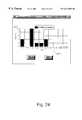
- FIG. 24illustrates diagramatically a screen display produced by the graphical user interface identified in FIG. 4 showing a link utilization chart.
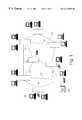
- FIG. 1there is shown schematically a circuit switched communications network comprising a plurality of node elements each comprising an item of node equipment for example a switch, and a plurality of link elements, connecting the node elements, each link element comprising an item of link equipment, eg terrestrial or wireless communication links.
- Each item of node equipmentmay comprise a plurality of individual physical components.
- Each item of link equipmentmay comprise one or a plurality of physical components.
- Each link equipmentmay support a plurality of communication channels.
- the communications networkmay include mobile phone communications apparatus resident at one or more nodes of the network and a node element may comprise a gateway to another network, for example a world wide web gateway.
- the communications networkwill comprise a variety of different types of node equipment and a variety of different types of link equipment, made by different manufacturers and having differing performance specifications.
- traffic data signalsare transmitted along the link equipment and through the node equipment over a circuit switched path between a source node element and a destination node element.
- the traffic datais carried between sources and destinations over a plurality of routes across the network.
- a network controller 104may be attached to a node equipment, the network controller comprising management functionality for managing routes or connections across the network.
- the network controllercomprises a modular route finder component which acts as a server for finding routes for connections in response to service requests generated by a plurality of different network management applications.
- the route finder componentmay support other network management applications resident on the network controller, for example the route finder component may support network topology design for synchronous digital hierarchy (SDH)/synchronous optical network (SONET) rings, or network design and bandwidth provisioning.
- SDHsynchronous digital hierarchy
- SONETsynchronous optical network
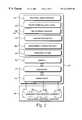
- FIG. 2 of the accompanying drawingsillustrates a schematic diagram of one embodiment of a network controller 104 .
- the network controllercomprises a general purpose computer, such as a Hewlett Packard 9000 series work station, comprising a memory 201 ; a processor 202 ; an operating system 203 ; a plurality of communications ports 204 through which data is transferred to and from communications node equipment hardware 205 ; a management information base (MIB) 206 holding data describing physical resources of a network, eg node equipment type, link bitrate capacity; route finder component 207 for routing service requests across the network, the route finder component comprising a route finder manager 208 and a route finder engine 209 , the route finder manager comprising one or a plurality of pre-processing components for pre-processing data prior to input to the route finder engine 209 , and one or a plurality or post-processors for processing data after output from the route finder engine; a plurality of network management applications 210 for managing services
- ATMsynchronous transfer mode
- SDHsynchronous digital hierarchy
- the route finder component 207may not provide a real time routing mechanism, but operates to develop and optimize routing strategies across the network in response to a plurality of service requests generated by the other network service applications 210 .
- the routing strategies produced by the route finder component 207are used to produce routing tables for use by conventional real time routing applications within the network.
- FIG. 3illustrates an example of a generic representation of a communications network, eg as illustrated in FIG. 1 .
- the generic network representationis viewed as a topology graph comprising a plurality of nodes 301 connected by a plurality of links 302 .
- Any node element equipmentcan be represented by a node 301 .
- Any link equipmentcan be represented by a link 302 between two nodes.
- the linkscan be unidirectional or bidirectional, depending on whether messages can be transmitted across the link in one or two directions respectively at any given time.
- Each node and linkhas a pre-determined finite bitrate transmission capacity.
- Network service applications running on the network controller or other workstations connected to the networkmay make a number of service requests which need to be implemented as connections between particular nodes.
- a service requestcan give rise to one or a plurality of connection requests.
- Each connection requestresults in requests for source to destination connections which must be routed across the network, in order to carry data traffic comprising the requested service.
- the service requestsmay specify the type of data traffic to be transferred, eg data or voice, a source node and one or more destination nodes.
- connectionmeans a circuit switched allocation of physical resources between a source node and one or more destination nodes.
- a “route”is defined as a path across one or a plurality of links, between a source node and a destination node. There may be several routes available for each pair of source/destination nodes.
- service requestsare received by the route finder component 207 which can assign routes to requested connections according to specific criteria such as avoiding overloading any specified link or node or attempting to utilize as many nodes/links in the network as possible at a given time.
- Each linkis assigned an associated cost, denoted by numerals C 1 -C 12 near the center of the link lines 302 in the general topology view of FIG. 3 .
- Assignment of costs to links for a networkis user specifiable. All costs can be uniform through the network or complex costs can be attached to links, for example relating to link utilization by connections. The costs can also be variable for different traffic types, for example resulting from voice or data connections.
- the route finder componentoperates to find routes having the minimum overall costs for connections to be routed between nodes in the network and thereby find routes which for example experience lower delay, or have faster, more reliable transmission.
- FIG. 4 of the accompanying drawingsillustrates a schematic diagram of a high level architecture of the route finder component 207 and associated input and output data operated on by the route finder component.
- the route finder engine 209preferably comprises a memory, and a processor executing one or more route finding algorithms.
- the route finder manager 208comprises a service request pre-processor 400 ; a network data pre-processor 401 ; an evaluation function processor 402 ; and a route data post-processor 303 .
- Each of the service request pre-processor, network data pre-processor, evaluation function processor and route data post-processormay comprise a processor element and an area of data storage device configured by means of algorithms for carrying out data traffic pre-processing, network data pre-processing, evaluation functions and route data post-processing respectively.
- External network management applicationsincluding service management applications send service requests to the route finder manager 208 and the route finder manager responds by returning a routing strategy for implementing those services.
- the routing strategyis produced in the form of routing table data 410 .
- the route finder engine 209receives input data from service request pre-processor 400 , network data pre-processor 401 and evaluation function processor 402 , and outputs data to route data post-processor 403 .
- the pre-processors 400 , 401 and 402are configured to convert data from external management applications into a generic form suitable for input into route finder engine 209 .
- the route finder enginecan also transfer data to and from a graphical user interface (GUI) 211 allowing an operator to obtain a visual display view of connections and routes taken by connections which are assigned or to be assigned by the route finder engine 209 .
- GUIgraphical user interface
- the service request pre-processor and network data pre-processorinput service request data, network topology data and switch definition data in an implementation specific format and convert this data into a format which is generic and not specific to any proprietary equipment types or transport protocols.
- the service request pre-processor 400 , network data pre-processor 401produce data files split into separate sections, each identified by a keyword. Each keyword describes a feature of the network topology or the service requests.
- the data fileis provided in standard ASCII format, and the information described under each keyword is input in a generic format, without specifying units of measurement.
- the route finder engine 209operates on the generic data produced by the pre-processors to produce generic output data, which is operated on by route data post-processor 403 prior to storing on the MIB.
- the service request pre-processor, network data pre-processor and route data post-processorare implemented as product specific components, that is to say, are configured to a type of node equipment, eg switch, MIB etc which is proprietary, and may be customized in each installation.
- the route finder engine 401 and evaluation processor 404are generic and re-usable from installation to installation.
- the service requests 407 , network topology data 408 , switch definition data 412 , routing objective data 409 , routing tables 410 and routing statistics 411may be stored on management information base 206 and are accessible to a plurality of other network management applications resident on the network controller, or elsewhere on the network.
- Data stored on the management information basemay be specific to particular proprietary network elements, and may be specific to particular transport mechanisms, eg ATM, SDH, SONET.
- Service request pre-processor 400receives input service request data in the from of a list of service requests 407 from an external application.
- a service requestmay specify:
- a traffic data typeeg voice, video, computer generated data
- the service request pre-processor 400converts the service requests 407 into a generic data format suitable for input to the route finder engine 209 .
- the input service request data 407may be specific to individual switch types, or transport protocol types.
- Service request pre-processor 400converts the service request data to produce a traffic matrix data for each traffic type. These matrices are transformed into generic service requests by service request pre-processor 400 , which are input into route finder component 207 to be routed across the network.
- the network data pre-processor 401receives input data describing the network 408 from Management Information Base 206 .
- the network datadescribes connectivity and topology of nodes and links of the network.
- the network datamay contain switch definition data 412 which describes network node elements' characteristics such as bandwidth capacity.
- the network topology datamay include:
- node namestheir bitrate capacities (peak or average) and their cell processing times
- link status datadescribing an amount of bitrate capacity already consumed by existing service requests
- node status datadescribing an amount of bitrate capacity already consumed by existing service requests
- the network data pre-processor 403converts the input network data into a generic form suitable for the route finder component 207 .
- Network data pre-processor 403receives the network data 408 including switch definition data 412 , which may be in a form specific to individual proprietary switches and link equipment, and generates generic network graph data which is input into route finder generic engine 209 . Since the network data 408 includes switch specific information, such switch specific information is converted to generic format by network data pre-processor 401 .
- An example of a switch specific informationis a bitrate capacity of a switch.
- Evaluation function processor 402receives a representation of routing objectives data 409 entered by a user.
- the evaluation function processor 402is used by the route finder engine's genetic algorithms to quantify efficiency/fitness of a particular set of routes found for the service requests it receives.
- Evaluation function pre-processor 402receives routing objective data 409 describing high level routing objectives specified by a network operator. Such high level routing objectives may comprise data describing constraints on routing.
- the evaluation function pre-processor 402assigns a fitness data to potential routing strategies specified in the routing objective data 409 . The assigned fitnesses are used by the route finder engine in searching for potential routes across the network.
- the route finder engine 209produces route data describing a list of routes for the service requests.
- the output route datais transferred to route data post-processor 403 which converts the route data into a routing table 410 .
- the route finder engine 209produces route data in generic format for each node in the network.
- the route data post processor 403converts the generic format route data into a product specific routing table form usable by the network switches.
- the routing table datais accessible by a connection control component of the node equipment switches for implementing the connections.
- the route finder engine 209also outputs routing statistics data 411 . A user can view and evaluate the routes found by the route finding component by inspection of the routing statistics data 411 stored on the MIB 206 .
- Routing statistics data 411may include data describing
- the route finder engine 209is configured to operate on generic network data produced by the service request pre-processor 400 , network data pre-processor 401 , and evaluation function processor 402 .
- the route finder engine 209operates according to an algorithm which performs an artificial intelligence search technique.
- the route finder engineoperates a genetic algorithm, although as an alternative, a simulated annealing algorithm, or a combination of a genetic algorithm and a simulated annealing algorithm may be applied by the search engine.
- the search algorithms of the route finder engine componentcan operate without using any problem specific knowledge.
- the search algorithmoptimizes its search for routes according to fitness data produced by evaluation function processor 402 .
- modularization and generalitymay be achieved, thereby allowing improvements to be made to the search algorithm independently of service request pre-processor 400 , network data pre-processor 403 , or evaluation function processor 402 .
- FIG. 5herein illustrates schematically route finder component 207 and examples of interactions with a network management application 500 .
- the network management application 500communicates with the route finder component 207 by a series of set, get and command signals (set request, set response, get request, get response, command request, command response) as illustrated in FIG. 5 .
- Network datais passed from the management application to the route finder component, enabling the route finder component to gain knowledge of the network across which the network management application requests to deploy a service.
- the route finder component 207finds an optimized set of routes for carrying the service, and returns data describing those routes to the management application 500 in the form of routing table data 410 .
- the route finder component 207determines the optimum routes in accordance with a set of default parameters.
- the default parametersare stored in the route finder component 207 and the management application 500 or a user may update, query or change the default parameters by means of the command request signals.
- route finder component 207a genetic algorithm implementation of route finder component 207 will be described. It will be understood that in other embodiments of the invention, the genetic algorithm search engine may be replaced by other artificial intelligence technique search engines, for example a simulated annealing search engine, or a combination of a genetic algorithm search engine and a simulated annealing search engine.
- the genetic algorithm search enginemay be replaced by other artificial intelligence technique search engines, for example a simulated annealing search engine, or a combination of a genetic algorithm search engine and a simulated annealing search engine.
- the route finder component 207comprises a plurality of data processing elements, each comprising a processor and an associated area of memory device carrying out specific processes as illustrated schematically in FIG. 6 .
- Datais transferred between processors as indicated in FIG. 6 herein.
- the symbol * associated with several of the processes in FIG. 6indicates that there is a data flow from control parameters data 612 to shortest path calculation process 603 , initial population generation process 604 , route generation process 605 , genetic manipulation process 606 , population reproduction process 607 , merge population process 608 , fitness evaluation process 402 , and Steiner Tree production process 610 .
- the functions of each of the processare as follows.
- Engine control processor 600controls invocation of all other processes within the route finder generic engine 209 .
- Profile generation process 601reads a data file containing data describing network topology and traffic demand information and processes it into an internal representation of the network and of traffic demands, both point to point and point to multipoint, placed upon the network by an application.
- a network data file output from network data pre-processor 401is input into profile generator process 601 .
- Control parameter data 611 describing parameters such as form example weighting co-efficients associated with a fitness evaluation process 609 carried out by evaluation function processor 402is also input into profile generation process 601 .
- Representation generation process 602operates on traffic demand representation data 612 , network representation data 613 output from profile generation process 601 and selected control parameter data 611 to compute a number of bits which are required by the genetic algorithm to represent a routing decision space, from which generic routing solutions will be found.
- Network representation data 613stores two “views” of the network. Firstly, a graph view of the network on which algorithms, eg k shortest path algorithm or minimum spanning tree algorithms can be run is stored in the network representation data 613 . Secondly, a view of the network which allows a mapping to external node and link names is stored. This view is generated during network data parsing, and is used principally during production of routes.
- the information stored for the network representation data 613includes: locations; links; link costs; graphs. Locations have the attributes: geographical position; name; capacity, ie the amount of traffic which can flow through a node.
- Linkshave the following attributes: link identifier; source node and port number; destination node and port number; capacity; current load, ie a load before traffic requests a routed; total load, ie a load after traffic requests are routed;
- Link costshave the attributes: link identifier; cost routing;
- Link cost informationis stored for all traffic types in the traffic demands which require routing.
- Graphshave the following attributes: number of nodes; degrees of each vertex.
- Shortest path calculation process 603operates a known Yen-Lawler algorithm on the network representation data 613 and traffic demand representation data 612 and outputs the shortest path data 616 comprising an integer number k shortest paths for each service request 407 input to the route finder component 207 .
- a genetic algorithm search routineis implemented by initial population generation processor 604 , genetic manipulation processor 606 , population reproduction processor 607 , merge population processor 608 , and fitness evaluation processor 609 .
- genetic algorithm processesare well known in the prior art and involve representing a problem as a series of bits or bytes of data in fixed length bit strings. Populations of fixed length bit strings are altered, combined, mutated and crossed over with each other and optimized bit strings are selected in accordance with a fitness criteria.
- routes across a network of nodes and linksare represented by bit strings of ones and zeros, which are mutated and combined to find optimum routes in accordance with routing objectives 409 input into a fitness evaluation function operated by evaluation function processor 402 .
- Initial population generation processor 604operating part of the genetic algorithm, computes a size of a routing decision space from which routes are to be found and produces an initial population of string data representing routes across the network.
- size of a decision spaceit is meant a number of possible different routes (each represented by a corresponding respective string).
- the strings in the initial populationdescribe randomly assigned routes across the network.
- an initial string population in which all shortest paths across the network have been assignedmay be generated.
- initial population generation process 604In generating the initial population of strings, initial population generation process 604 inputs representation definition data 614 generated by representation generation process 602 , and operates in accordance with various control parameters specified in the control parameter data 611 .
- a current population of strings represented by current population data 615is input into population reproduction process 607 .
- Population reproduction process 607takes the current population and reproduces the population of strings based upon the values of several control parameters specified in control parameter data 611 , and in proportion to a “fitness” of the individual strings of the population of strings, to produce an intermediate population of strings represented by intermediate population data 618 .
- the fitness criteriaare specified in fitness data 619 , which are input into population reproduction process 607 .
- Genetic manipulation process 606inputs the intermediate population data comprising an intermediate population of strings, applies known mutation and cross over process and thereby generates a manipulated population of strings. This process mixes the strings contained in the intermediate population.
- the current population, intermediate population and manipulated populationare merged by merge population process 608 , according to parameters specified in control parameter data 611 and according to fitness values of each member of the population as determined by fitness evaluation process 609 outputting fitness data 619 .
- the fitness evaluation process 609inputs data strings comprising population members from the current, intermediate and manipulated population data, decodes them and simulates routing of traffic using the network representation data based on the current, intermediate and manipulated population members.
- a fitness functionis evaluated according to control parameters specified in control parameter data 611 as will be described hereinafter.
- a fitness value for each population memberis generated.
- Each point to point connection requestcorresponds to a source node and a destination node.
- a plurality of routes of linksare determined using a known algorithm, eg the known Yen-Lawler algorithm.
- a set of (for example 8) shortest routesare stored in a look-up table, and the 8 shortest routes are converted to bit string representations to form bit string population members which are manipulated according to genetic manipulation process 606 .
- Route generation process 605periodically selects optimum population member strings from the current population, with a period which may be specified by the user in control parameter data 611 , and decodes the strings into routing information for point to point and point to multipoint service requests. This information is printed as text information and is available to a user via graphical user interface 211 .
- an external network management application 500sends commands to the route finder component 207 such as get, set, execute or command, and arguments of these commands control execution of the route finder component 207 .
- the get and set commandsallow general interaction with control parameter data 611 under control of engine control process 600 .
- the Command instructioncauses the search engine to begin a search for optimal routes.
- the genetic algorithm search engineinteracts with the representation generation process 602 and shortest path calculation process 603 in order to
- the representation generation process and shortest path calculation processorare pre-processing steps in the route selection process. Each time the management application 500 requests a set of new routing solutions, the representation generation process and shortest path calculation process are operated in an initialization phase prior to operation of the search for routes.
- a current population of data strings generated by initial population generation process 604is input as current population data 615 into fitness evaluation process 609 .
- Fitness evaluation process 609generates fitness data 619 corresponding to the current population of strings.
- the fitness data and current population datais used by the population reproduction process to generate an intermediate population of strings output as intermediate population data 618 .
- Each string of the intermediate populationhas its fitness evaluated by fitness evaluation process 609 resulting in fitness data 619 describing a fitness value for each string comprising the intermediate population of strings.
- the manipulated population of strings represented by manipulated population data 617has its fitness evaluated by fitness evaluation process 609 resulting in fitness data 619 representing a fitness of each string of the manipulated population.
- Data describing the three populations of strings, ie the current population, intermediate population and manipulated population, along with fitness value data corresponding to each string of the current, intermediate and manipulated populationsare input to the merge population process 608 which generates a new current population of strings represented by current population data 615 based upon selection of fittest strings from each of the current, intermediate and manipulated populations.
- the cyclecompletes by route generation process 605 computing a plurality of routes based upon one or more fittest strings of the current population, and returning these computed routes to network management application 500 as routing tables 400 , after first converting the output route data to a form suitable for input to the management application 500 in route data post-processor 403 .
- Generation of new routesis conditional upon control parameters stored in control parameter data 611 , specified by network management application 500 .
- the generation of new route dataterminates when population reproduction processor 607 determines that a predetermined number of evaluations specified in the control parameters data 611 have been performed.
- the route finder component 207then waits for further commands from the network management application 500 before generating further route table data.
- fitness evaluation process 609uses shortest path data and Steiner Tree data to accord a fitness parameter to the string members of the populations. Whilst shortest path information is generated only once in response to a request for routing from the network management application 500 , Steiner Tree data is generated for each member of each population. Thus, Steiner Tree production is invoked for a point to multipoint service request.
- interfacing between the service request pre-processor 400 , network data pre-processor 401 , evaluation function pre-processor 402 , route data post-processor 403 and route finder engine 209is made by way of reading and writing data from a plurality of results data files, which are written in simple ASCII protocol.
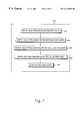
- FIG. 7herein illustrates steps executed by the route finder component 207 .
- data describing service requests 407is entered into service request pre-processor 400 which produces a Simple ASCII Protocol (SAP) file describing the service requests which is entered into the route finder engine 209 .
- SAPSimple ASCII Protocol
- network topology data 408is entered into network data pre-processor 401 which outputs a SAP file describing relationships between nodes and links in the network.
- the SAP fileis entered into the route finder engine 209 .
- a SAP text file containing data representing routing objectives 409 input by a useris entered into the route finder engine 209 .
- the route finder engine 209preferably uses genetic algorithms to route the service requests it receives as input on the network described in its input according to the entered routing objective data 409 evaluation function.
- the route finder engine 209outputs a SAP file containing a list of routes for the connection requests.
- the SAP filemay be entered into the route data post-processor 405 at step 705 in order to convert the route data SAP file into a form suitable for use by the external application which made the service requests.
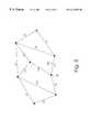
- route finder component 207A set of routing strategies carried out by route finder component 207 will now be described. To aid understanding the operations are described as operations on single node and link network graph representations as shown schematically FIGS. 8 and 9 herein. It will be understood that the graphs shown and the routes selected are implemented as machine executable data processing operations on data representing nodes and links of a network.
- FIG. 8 of the accompanying drawingsillustrates the generic network graph of nodes and links illustrated in FIG. 3.
- a grid of coordinates 803is superimposed upon the network graph, such that each node is assigned a unique XY coordinate position.
- Links between nodesare assigned associated costs, (denoted in FIG. 8 by numerals near the center of the link lines).
- Each link in the generic network graphis assigned a link cost.
- Link cost informationis specified in connection requests of the request for services which require to be routed.
- a cost of a single linkmay be different for different traffic data types.
- a route costcomprises a summation of links included in that route.
- a connection costcomprises a summation of all route costs for all routes in a connection for a particular service request.
- route finderFor a connection between a source node 801 , labeled n — 1 and a destination node 802 labeled n — 8 is indicated by links having directional arrows. Configured for shortest path routing, the route finder preferably finds minimum cost routes for a list of connection requests between such pairs of source and destination nodes in the network.
- the route findermay be configured to “balance” connections across the network. Balancing the connections may be achieved by taking into account an integer number K shortest paths between the source and destination node of each connection, and selecting the shortest path for each connection which yields an even distribution of network node and link utilizations.
- FIG. 8herein illustrates a generic network graph of nodes and links illustrating how balancing of traffic across the network is achieved.
- a shortest path routingwould force traffic between source S node n — 1 and destination node n — 7 and traffic between source 801 node n — 1 and second destination 802 node n — 8 through nodes n — 2 and n — 6, placing congestion on nodes n — 2 and n — 6, by considering an integer number k shortest paths, traffic from source n — 1 to first destination n — 7 may be routed through alternative nodes n — 3 and n — 5, whilst traffic between source n — 1 and second destination n — 8 may continue to be routed through nodes n — 2 and n — 6, thereby balancing traffic across different routes of the network and achieving more uniform loading of nodes and links with traffic data.
- the route finder component 207may route a single connection over several different routes. This “splitting” of connection over routes may be necessary where the connection requires a high bandwidth capacity.
- the number of routes over which such a connection request may be splitcan be entered by a user, or the route finder itself may decide the number of routes over which to split the connection request up to a user defined upper band.
- the percentage of bandwidth capacity of a connection request to be divided across the number of selected routescan also be chosen by the user. For example, if the connection request's bandwidth capacity is to be divided across a first and a second route then 30% of the connection request's bandwidth capacity can be carried across the first route and 70% of the connection request's bandwidth capacity can be carried by the second route.
- a single connectionmay be distributed across multiple paths across the network. Traffic between source node n — 1 and destination node n — 7 in response to a service request may be carried over an integer number of multiple paths. For example, a first route may traverse nodes n — 2 and n — 6, carrying 70% of the data of the service. A remaining 30% of the data of the service may be routed via nodes n — 3 and n — 5.
- the distribution of routesmay be user specified, or alternatively optimized by genetic algorithms.
- a default condition whereby a single route carries all traffic relating to a source-destination service requestmay be set by a user.
- FIG. 9 of the accompanying drawingsillustrates the network graph nodes and links shown in FIG. 8 but with the network links having multiple costs, denoted by numerical values separated by a slash symbol (/).
- the multiple costsmay be associated with different traffic types, eg voice or data.
- the route finderany select paths for connections taking into account the traffic type used by the connection.
- the route finder component 207may deal with point to multipoint traffic as illustrated with reference to FIG. 9 herein as follows. For traffic originating at source node n — 1 and terminating at multiple destinations nodes n — 8 and n — 7, routes n — 1, n — 2, n — 6, n — 8 and routes n — 1, n — 3, n — 5, n — 7 may be selected, or routes n — 1, n — 2, n — 6, n — 7 and route n — 1, n — 2, n — 6, n — 8 may be selected. Other combinations are possible even in the simple example illustrated with reference to FIG. 9 . Further, for point to point or point to multipoint services, routing may be selected according to traffic data type.
- a usermay interact with a route finder component 207 by use of graphical user interface 211, to edit and alter data already input from a network application or to enter data directly.
- Data editing and entryis achieved by manipulation of a cursor icon using a computer peripheral pointing device, eg a mouse, trackball device or similar, across a series of display screens, various ones of which are described hereunder.
- FIG. 10 of the accompanying drawingsillustrates a network data editor screen display which a user may use to create or edit network topology data.
- the network data editorwhich is part of the GUI 211 , may be used to produce network data for the route finder engine 209 as an alternative to network data pre-processor 401 receiving network topology data 408 and converting it to an SAP file.
- Nodes 1001appear on the display window of a screen as icons and given labels 1002 . Links between nodes can also be drawn, represented by lines 1003 .
- the displayincludes a horizontal scroll bar 1005 and a vertical scroll bar 1004 which the user may use to draw a network topology of greater area than currently shown in the display window.
- the network topology data drawnis saved using a file name 1006 .
- the file savedis preferably a file conforming to the SAP format.
- FIG. 11 of the accompanying drawingsillustrates a link data editor screen display which a user may use to edit data describing network links.
- the link data editor part of the GUI 211may be used to produce network data for the route finder engine 209 as an alternative to network data pre-processor 401 receiving network topology data 408 and converting it to an SAP file.
- the screen displaycomprises a dialog box showing a name of a link, that is, the link's two end points (each end point having a node label and a port number).
- the displayalso comprises two icons 1102 which may be used to specify whether the link is for full duplex or half duplex (ie bi or uni directional, respectively).
- a bandwidth capacity of the linkmay also be edited by selecting a numerical value which is presented in a scroll menu display 1103 .
- Costs associated with a linkmay also be entered and edited, for example a cost of voice data for the link may be edited by entering a numerical value 1104 , in a cost data entry portion of the display window 1104 .
- data traffic 1105For data traffic 1105 .
- FIG. 12 of the accompanying drawingsillustrates an example of a text file having SAP format which may be entered into the route finder engine from network data pre-processor 403 or resulting from the network topology data editor shown in FIG. 10 or the link data editor shown in FIG. 11.
- a file in SAP formatmay comprise a plurality of lines containing ASCII characters with each line terminated by an ASCII new line character.
- the SAP filecomprises a plurality of sections, with each section having a header line followed by one or more data description lines.
- a header line 1201 for a node sectioncomprises:
- a node description line 1202comprises a node label which acts as an identifier for the node, XY coordinates corresponding to a coordinate grid of a node and a numerical value denoting capacity.
- An example node description linecompnses:
- a link section describing network linkshas a header line 1203 comprising:
- a link description line 1204defines a single link between a pair of nodes.
- a link description linemay comprise two end points (each end point described by a node label and a number representing a node port), a value denoting the total capacity of the link and an identifier indicating whether the link is simplex or duplex (ie whether traffic on the link can be uni- or bidirectional).
- An example of link descriptioncomprises:
- a header line 1205 for a link state sectioncomprises:
- a description line describing link state capacity usage 1206may comprise two end points and a numerical value denoting link capacity used, eg:
- This examplerepresents a link between port 1 of node n — 1 and port 1 of node n — 2, having 402 units of capacity already allocated.
- the route finder enginedoes not place unit of measurement on the number of 402 units. Thus, as long as the capacity and load utilization are measured in the same units, the numerical values denoting capacity and load can both be sent to the generic route finder engine 209 .
- a header line 1207 of a node state sectioncomprises:
- a node state description line 1208may comprise a node label (which should be already defined in a node description section, any lines containing undefined node labels will be ignored) and a value denoting current capacity utilization of the node, for example:
- node n — 1has a present allocated capacity of 1.
- No unit of measurementis placed on the file by the generic route finder engine, since the route finder manager 208 sends all data to the generic route finder engine in the same units.
- a header line 1209 for a link reliability sectioncomprises:
- a link reliability description line 1210 defining reliability of a single linkmay comprise two end points (each having a node label and a port number) and a real number having a value between 0 and 1.0 (1.0 denoting 100% link reliability), eg:
- This examplerepresents a link between port 1 of node n — 1 and port 1 of node n — 2, having a link reliability factor of 0.999.
- a header line 1211 for a node reliability sectioncomprises:
- a description line 1212 defining reliability of a single nodecomprises a node label and a real number having a value between 0 and 1.0 (1.0 denoting 100% node reliability):
- a header line 1213 for a costs sectioncomprises:
- a description line 1214 defining the cost of a single linkcomprises two end points (each end point having a node label and a port number) and one or more data types with a numerical value representing the cost, eg:
- This exampleillustrates a link between port 2 of node n — 1 and port 3 of n — 2 which has a cost value of 1 for data service traffic and a value of 2 for voice service traffic. That is to say, the link has a lower cost for data traffic than for voice traffic.
- the measurement of costhas no unit.
- the cost valueis used by the generic route finder engine to find shortest paths from which a final choice of paths is made and is used in the calculation of minimum spanning trees.
- FIG. 13 of the accompanying drawingsillustrates a screen display which can be used to generate service requests.
- the screen displayis generated by a service request generator, part of the GUI 211 , which may be used to generate service requests for the route finder engine 401 as an alternative to service request pre-processor 400 receiving service requests from an external application and converting them to a SAP file.
- the screen displaycomprises a two dimensional table in which vertical entries 1301 represent source nodes and horizontal entries 1302 represent destination nodes of connections. Entries 1303 in the table represent service request numbers for connections between the entry's source and destination nodes.
- the displayalso includes a selector 1304 used to select the type of traffic, eg voice or data, required by the service requests.
- FIG. 14 of the accompanying drawingsillustrates a screen display which can be used to create or edit data representing constraints on routes found for specified service requests.
- the screen displayis generated by a constraints data creator part of the GUI 211 , which may be used as an alternative to service request pre-processor 400 receiving service requests from an external application including route constraints and converting them to a SAP file.
- the screen displaycomprises a dialog containing a scroll box 1401 which may be used to select a source node.
- the displayalso comprises a scroll box 1402 which may be used to select destination node(s).
- the displayalso comprises a scroll box 1403 used to select the traffic type between the selected source and destination nodes which is to be constrained.
- the displaycomprises two selection boxes 1405 used to select whether nodes or links are to be selected.
- buttons 1404are also used to select whether the selected nodes or links will be excluded or included from the route.
- a list of nodes or links 1406is also shown in the display, depending upon whether nodes or links were selected using selection boxes 1405 . Nodes or links may be selected from list 1406 in order to generate constraints which will be included or excluded for routes found between the selected source and destination nodes selected using scroll boxes 1401 and 1402 , respectively.
- FIG. 15 of the accompanying drawingsillustrates an example text file having SAP format which may be entered into the route finder engine from an external application via service request pre-processor 400 or by the traffic data editors shown in FIG. 13 and FIG. 14 .
- the example shown in FIG. 15illustrates sections defining data relating to network traffic.
- the SAP filecomprises a number of sections, with each section having a header line and one or more description lines.
- a header line 1401 for a traffic sectioncomprises:
- a description line 1502 for a point-to-point service requestcomprises a numerical identifier for the service request, a source node label, a destination node label, a numerical value denoting capacity required by the service, a traffic type identifier and a numerical value denoting number of routes over which to split total capacity requirement, and a splitting mechanism.
- the splitting mechanismmay be a symbol * indicating that the route finder engine determines a percentage split of traffic over the indicated number of routes, rather than this split being determined in the service equipment.
- a service request identified as service request 983comprises a point to point request for service connection between node n — 1 and n — 8 having a consumption of 165 units of bandwidth, and which is to use 5 routes.
- the symbol*denotes that the percentages of data traversing each of the 5 routes are to be determined by the generic route finder engine.
- the point to point service request description linewill include numerical values instead of the symbol * which denotes the percentage split, for example to split capacity equally (50% to 50%) over two routes. For example:
- the service request identified as number 984 between node n — 2 and n — 3 having capacity consumption of 210 unitscarries voice data traffic over 2 routes split equally at 50% over each route.
- a header line for a multi-point section 1504comprises:
- a description line 1505 defining a point to multi-point service requestmay comprise a numerical service request identifier, a source node label, a plurality of destination node labels and a numerical value denoting capacity required by the service request. For example:
- This exampleindicates a service request identifier 985 being a multi-point connection between node n — 1, and nodes n — 2 and n — 3 with a bitrate consumption of 160 data units, carrying data type traffic.
- a header line 1506 for a constraints sectioncomprises:
- a description line 1507 defining links which should be included in a route for a particular service requestcomprises a numerical value corresponding to a defined service request (point to point or point to multi-point), the word “include”, the word “link”, and a list of one or more links with each link listed comprising two end points (each end point comprising a pair of node labels and ports), eg:
- This exampledenotes a service request identified as number 983 including links between Port 1 of node n — 1 and Port 1 of node n — 2, and Port 2 of node n — 2 and Port 2 of node n — 3.
- a description line 1508 defining nodes to be excluded from route(s) found for a particular service requestcomprises a numerical service request identifier, the word “exclude”, the word “node” and a list of node labels, eg:
- nodescould be included from the route(s) found for the service request by replacing “exclude” with “include”.
- FIG. 16 of the accompanying drawingsillustrates an example of a SAP format file.
- the example file shown in FIG. 16includes sections defining evaluation function related parameters. Data describing parameters which the route finder engine's genetic algorithms may consider when determining routes for service requests are described in a problem parameters section.
- a header 1601 for a problem parameters sectioncomprises:
- Routing objective data 409 which the route finder engine takes into account when finding routes for service requestscan be given a weighting in order to determine which route selection to make in certain circumstances. For example if having a short as possible route for each connection was twice as important as balancing utilization of nodes and links across the network then description lines 1602-1603 for a problem parameters section could include:
- a header line 1604 for a GA parameter sectioncomprises:
- the GA parameter section's description linescomprise parameters and their values, for example a number of iterations which the route finder may run its genetic algorithms on input data may be set by:
- the SAP files illustrated in FIG. 12, FIG. 15 and FIG. 16 of the accompanying diagramsmay be included in one SAP file and entered into the route finder engine 401 .
- FIG. 17 of the accompanying drawingsillustrates steps executed during step 704 of FIG. 7 which applies the route finder's genetic algorithms to find routes for the service requests entered.
- the parameters and instructionsare entered into the route finder engine.
- the parameters which may be enteredcomprises variables which may be used to control the route finder engine's genetic algorithms.
- the variablesmay be given values by us ing a “set” which has a instruction of the form:
- ⁇ variable name>is a name of a supported route finder engine variable
- ⁇ value>is a value to be assigned to the variable
- the v ariables supported by the GA meter enginecomprise:
- the instructions which may be entered into the route finder engineinclude a “command” instruction.
- the command instructionsare interpreted by engine control process 600 of the route finder generic engine 209 to load or save files, start an optimization process, or terminate operation of the generic route finder engine.
- a command instructionhas a number of distinct forms, including:
- command resetcauses a random initial population to generated
- command runcommences the search for routes for entered service requests
- command load/saveallows route finder engine data to be loaded or saved to an external store such as a disc drive.
- Route finder engine datawhich may be saved or loaded includes the parameter variables and values described above and routes found by the route finder engine.
- a batch file comprising “set” and “command” instructionsmay be created and saved using a filename.
- Such a batch filemay be executed by the route finder engine by an instruction:
- a representation for a route for a point-to-point connection requestcomprises a string of contiguous bits.
- FIG. 18 of the accompanying drawingsillustrates as an example a graph 1801 of nodes (labeled in n — 1 to n — 8) and links.
- array 1802contains eight entries, each entry comprising a list of nodes in a route between node n — 1 and node n — 2 of graph 1801 .
- Each entryis calculated using the known Yen-Lawler algorithm which produces k (where k is an integer) shortest routes between any two nodes in a graph.
- the path between node n — 1 and n — 2 highlighted in graph 1801 by black nodes and directional arrows on linkscorresponds to the path stored in entry 2 (010 in binary) of array 1802 .
- Arrays of eight shortest routes for each pair of nodes in the networkare created during the generate representation step 1802 .
- array 1803contains eight shortest routes between node n — 1 and node n — 3 of graph 1801
- array 1804contains eight shortest routes between node n — 7 and node n — 8 of graph 1801 .
- the representationdefines lengths of bit strings used by the route finder's genetic algorithms.
- Point to point connection requestsare effectively represented as an index into a look-up table. Because a same number of routes are computed for each point to point connection request, each request has a same bit string length representation, and so every member in the population also has a fixed length of bit string.
- the route finder engineuses the representation generated to search for routes for entered point-to-point connection requests according to the parameters and instructions entered at step 1701 .
- FIG. 19 of the accompanying drawingsillustrates steps executed by the route finder engine to route point-to-point connection requests at step 1703 of FIG. 17 .
- the route findercreates an initial population each member of which comprises a bit string having a length determined by the representation generated at step 1702 .
- the bit string lengthis determined by the number of paths computed for each connection request, multiplied by the number of connection requests, ie a search “space” of possible route solutions.
- the initial population generatedcomprises a plurality of members, each member having random bit values. Random bit values in the bit strings for each point-to-point connection request represent for example a 3 bit binary number which is used to index the array of for example eight shortest routes for that point-to-point connection request, see 2001 and 2002 of FIG.
- the number of paths usedis user configurable, and the number of bits needed to represent the number of paths used is calculated according to log (k)/log (2), where k is the number of paths chosen.
- Output of the initial population generation step 1901is called a current population 2003 .
- a fitness evaluation processis invoked in order to compute a fitness of each current population member. The current population in then sorted according to its fitness. The fitness evaluation process assigns a single numerical value 2006 to each population member in order that the members can be ranked and used in later steps of FIG. 19 .
- the fitness evaluation processindicates increased desirability of a population member by a lower fitness numerical value, that is, the route finder engine's genetic algorithms search for a minimum numerical value.
- the fitness numerical value of each population memberis calculated by using the binary numbers encoded within the bit string for each point-to-point connection request to index that connection request's eight shortest routes array— 2004 .
- the cost of traversing the links of the indexed routeis then calculated and a numerical value is produced for each route— 2005 .
- a numerical value denoting the fitness evaluation of the population memberis then calculated by adding up the numerical cost of each route of each point-to-point connection request in the population member to give a numerical fitness value 2006 .
- the intermediate populationis generated by sampling—with replacement—the current population according to a distribution which is fitness related and defined by parameters entered into the route finder engine at step 1901 in accordance with routing objective data 409 .
- the intermediate populationis the same size as the current population and has a decreased average fitness numerical value, ie more desirable, when compared to that of the current population.
- the intermediate populationis genetically manipulated to produce a manipulated population.
- the genetic manipulationinvolves cross-over and mutation operations.
- FIG. 21 of the accompanying diagramsillustrates an example of genetic manipulation. Two intermediate population members, each being a string of nine bits are shown.
- the cross-over operationinvolves swapping a number of bits of one population member with another, the number of bits being determined by parameters entered into the route finder engine at step 1701 .
- a first intermediate population membercomprises of five left most bits 2101 and four right most bits 2102 .
- a second intermediate population membercomprises five left most bits 2103 and four right most bits 2104 .
- the cross-over operatoris set up to swap five left most bits of population members.
- the first intermediate population membercomprises five left most bits 2103 and four right most bits 2102 and the second intermediate population member comprises five left most bits 2101 and four left most bits 2104 .
- a bit wise mutation operationis applied to the crossed-over population members.
- the mutation operator usedis determined by parameters entered into the route finder engine at step 1601 . In the example shown in FIG. 21 the bit wise mutation operation results in a single bit of each 9 bit long population member being inverted.
- the fitness evaluation processis invoked in order to compute the fitness values of the manipulated population.
- the genetic manipulation processsorts the manipulated population according to fitness value.
- Balancing of traffic across the networkis achieved as follows: firstly, an initial population of routes is selected from a plurality of routes generated for each source destination node pair which, whilst including a shortest path between a source node and destination node, also includes a plurality of other routes between the source and destination node which are not the shortest path.
- the selected routes for a source destination pairinclude for example the 8 shortest paths generated by a known shortest path algorithm, eg Yen-Lawler algorithm.
- a number of shortest paths generated per connectionis specified in a SET and GET variable numpaths.
- mutation, cross over and reproduction processes within the genetic algorithmintroduce routes which are not shortest routes into a population of strings of bits representing routes.
- the fitness criteriamay be user specified to favor selection of bit strings which produce a relatively even distribution of link utilization across the network.
- the amount of capacity already utilized at each nodeis contained in the [nodestate] section of the SAP file.
- the amount of capacity already used on each linkis contained in the [linkstate] section of the SAP file.
- bit strings representing populations of routes which result in a relatively more even distribution of amounts of capacity utilized at the nodes and linksare favored. For example, bit strings representing routes which cause utilization of a node or link above a predetermined threshold parameter may have a lower probability of being selected for inclusion in successive populations.
- a network operatormay monitor utilization of individual nodes and links using a screen display as illustrated with reference to FIG. 24 herein.
- a merge populations processis executed.
- the function of the merge population processis to take members of the current, intermediate and manipulated populations and form a new current population. Mechanisms used in this merged populations process are determined by particular control parameters entered at step 1701 .
- the new current population generated at step 1904has its fitness evaluated by the fitness evaluation process described above. Depending upon the number of iterations of genetic operations to be performed, determined by parameters entered at step 1701 , control may be passed back to step 1902 or the genetic algorithms may terminate at step 1906 .
- the route finder engineoutputs a list of routes corresponding to population members having the minimum fitness numerical value, ie the most desirable.
- the list of routesis generated by listing the nodes contained in the shortest path array element indexed by the bits for each point-to-point connection request in the fittest population member.
- the route finder engineoutputs an SAP format file with a section describing the routes found for the service requests entered, an example of which is given in FIG. 22 herein.
- a header line 2201 for a routes sectioncomprises:
- a description line for a route sectionshas the following format:
- ⁇ no>comprises a numerical value corresponding to a service request number.
- ⁇ source>comprises a label of the point-to -point connection request's source node.
- ⁇ destination>comprises a label of the point to point connection request's destination node.
- ⁇ traffic type>comprises the type of traffic being routed, eg data or voice.
- ⁇ route>comprises a specification of the route found for a point-to-point connection request, specified as:
- nka label of a node in the found route
- Pka port used on the node.
- An example of a route sections of description line 2202may be:
- a SAP file containing a routes sectionmay be converted by route data post processor 403 into a routing table suitable for the external application which made the service requests.
- FIG. 23 of the accompanying diagramsillustrates a screen display which GUI 211 may produce to graphically illustrate a routing table using data produced by the route finder engine 209 .
- the screen displaycomprises a window with a table 2301 , each row of which represents a service request between a source node and a destination node of the network and each column of which represents a hop, ie a node contained in a route found for the service request.
- the screen displayalso comprises two selection buttons 2302 which may be used to show routing tables for traffic of different types, eg voice or data.
- the displayalso comprises a horizontal scroll bar icon 2204 and a vertical scroll bar icon 2303 which may be used to display connection requests and hops not visible in the current display.
- FIG. 24 of the accompanying drawingsillustrates a screen display showing a chart produced by GUI 211 using data produced by the route finder engine 209 .
- a horizontal axis 2401 of the chartillustrates percentage utility of links in the network, whilst a vertical axis 2402 of the graph represents frequency of the percentage utilization.
Landscapes
- Engineering & Computer Science (AREA)
- Computer Networks & Wireless Communication (AREA)
- Signal Processing (AREA)
- Data Exchanges In Wide-Area Networks (AREA)
- Telephonic Communication Services (AREA)
Abstract
Description
| Name | Meaning |
| crossoverProb | Crossover Probability |
| mutationProb | Mutation Probability |
| poolSize | Size of population |
| miniParents | Minimum number of parents |
| maxParents | Maximum number of parents |
| subpopPercentOfChromosomes | Percent of population selected |
| lambda | Used in exponential selection |
| mechanism | |
| bestFitInnacuracy | Used in merging solutions |
| tendencyPressure | Pressure applied in selecting solutions |
| replacePressure | Pressure applied when merging |
| solutions | |
| mergeMechanism | Mechanism used when merging |
| solutions | |
| crossoverMechanism | Mechanism used in crossover |
| noOfCrossoverPoints | Number of crossover points |
| selectedMechanism | Mechanism used for selection |
| statsCollectionMechanism | Mechanism used for selection |
| statsCollectionMechanism | Collects stats, per generation or |
| new solution | |
| randomSeedMechanism | Mechanism used for random seed |
| generation | |
| randomSeed | Random seed used |
| terminateAfterTime | Force experiment termination |
| after time | |
| maximumTime | Maximum time allowed |
| terminateAfterGens | Force termination after specified |
| generations | |
| maximumGens | Maximum generations allowed |
| maximumNoChangeGens | Maximum number of generations |
| allowed without finding a | |
| new solution | |
| statsFileFormat | Format of statistics file |
| noExperiments | Number of experiments to perform |
| experimentTime | Total experimental time allowed |
| problemFileName | Name of the file containing the |
| Network Data | |
| solutionFileName | Name of the file to be used to |
| store solution | |
| statisticsFileName | Name of file to be used to store |
| statistics information | |
| settingsFileName | Name of file to be used to store |
| the Route Finder engine settings | |
| experimentFileName | Name of file containing experimental |
| definitions | |
| summaryFileName | Name of the file to be used to |
| store summary information | |
| statsUpdateFreq | Frequency with which routes are |
| generated | |
| expStatsFileName | Name of the file to be used as a |
| base in computing file names used | |
| to store experimental results | |
| steps | Number of evaluations to perform |
| before stopping | |
| pathLengthWeight | Path length/cost weighting coefficient |
| for objective function | |
| balancingWeight | Link utilization balancing weighing |
| coefficient for objective function | |
| bestPathSeed | Use the best paths to seed a member |
| of the population | |
| variables | Used to get a list of all variables |
| that can be modified/read within the | |
| route finder engine, ie | |
| the first column of this table | |
| numPaths | The number of shortest paths to |
| compute for each point to point | |
| traffic demand | |
| variables | The variables defined within |
| RouteFinder | |
| population | The bitstrings which constitute the |
| current population | |
| diversity | A floating point value between 0 and |
| 1 which indicates the genetic variety | |
| of the population. A value closer | |
| to zero indicating a less-diverse | |
| population | |
| statistics | Text which describes the performance |
| of RouteFinder | |
| cellLossWeight | Weighting associated with the cell |
| loss term in routing objective | |
| cellDelayWeight | Weighting associated with cell delay |
| term in routing objective | |
| linkReliabilityWeight | Weighting associated with link |
| reliability term in routing objective | |
| nodeReliabilityWeight | Weighting associated with node |
| reliability term in routing objective | |
| nodeUtilizationWeight | Node utilization balancing weighting |
| coefficient in routing objective | |
Claims (6)
Priority Applications (1)
| Application Number | Priority Date | Filing Date | Title |
|---|---|---|---|
| GB9825804AGB2332815A (en) | 1997-12-24 | 1998-11-26 | Traffic route finder in communications network |
Applications Claiming Priority (2)
| Application Number | Priority Date | Filing Date | Title |
|---|---|---|---|
| GB9727163 | 1997-12-24 | ||
| GB9727163AGB2332809A (en) | 1997-12-24 | 1997-12-24 | Least cost routing |
Publications (1)
| Publication Number | Publication Date |
|---|---|
| US6314093B1true US6314093B1 (en) | 2001-11-06 |
Family
ID=10824110
Family Applications (2)
| Application Number | Title | Priority Date | Filing Date |
|---|---|---|---|
| US09/044,889Expired - LifetimeUS6310883B1 (en) | 1997-12-24 | 1998-03-20 | Traffic route finder in communications network |
| US09/088,805Expired - LifetimeUS6314093B1 (en) | 1997-12-24 | 1998-06-02 | Traffic route finder in communications network |
Family Applications Before (1)
| Application Number | Title | Priority Date | Filing Date |
|---|---|---|---|
| US09/044,889Expired - LifetimeUS6310883B1 (en) | 1997-12-24 | 1998-03-20 | Traffic route finder in communications network |
Country Status (5)
| Country | Link |
|---|---|
| US (2) | US6310883B1 (en) |
| EP (1) | EP0926860B1 (en) |
| CA (1) | CA2256223C (en) |
| DE (1) | DE69832140T2 (en) |
| GB (1) | GB2332809A (en) |
Cited By (94)
| Publication number | Priority date | Publication date | Assignee | Title |
|---|---|---|---|---|
| US20020004843A1 (en)* | 2000-07-05 | 2002-01-10 | Loa Andersson | System, device, and method for bypassing network changes in a routed communication network |
| WO2002046947A1 (en)* | 2000-12-04 | 2002-06-13 | Rensselaer Polytechnic Institute | System for proactive management of network routing |
| US20020083194A1 (en)* | 2000-11-04 | 2002-06-27 | Bak Sang Man | Routing method for traffic load distribution in packet-switched network |
| US20020112196A1 (en)* | 2001-01-11 | 2002-08-15 | Utpal Datta | Distributed processing and criteria-based dynamic modification of data-flow map |
| US20030023750A1 (en)* | 2001-07-24 | 2003-01-30 | Erol Basturk | Control method for data path load-balancing on a data packet network |
| US20030128710A1 (en)* | 1998-12-28 | 2003-07-10 | Fedyk Donald Wayne | Quasi-deterministic gateway selection algorithm for multi-domain source routed networks |
| US20030144748A1 (en)* | 2002-01-30 | 2003-07-31 | Mitsubishi Denki Kabushiki Kaisha | Apparatus for optimizing combinatorial optimization problems |
| US20030177264A1 (en)* | 2002-03-14 | 2003-09-18 | Ferhan Elvanoglu | Measuring performance metrics of networked computing entities by routing network messages |
| US6631128B1 (en)* | 1999-05-27 | 2003-10-07 | Telefonaktiebolaget L M Ericcson (Publ) | Core network optimization of topology and technology for traffic handling |
| US20030195984A1 (en)* | 1998-07-15 | 2003-10-16 | Radware Ltd. | Load balancing |
| US6643699B1 (en)* | 1999-03-10 | 2003-11-04 | International Business Machines Corporation | Computerized method for computing the overall splitting cost of a data structure using blocking island contour map of a network-level graph |
| US6681248B1 (en)* | 2000-04-12 | 2004-01-20 | Sycamore Networks, Inc. | Method for port connectivity discovery in transparent high bandwidth networks |
| US20040044761A1 (en)* | 2002-09-03 | 2004-03-04 | Phillipi Mark P. | Systems and methods for broadband network optimization |
| US20040049595A1 (en)* | 2001-12-04 | 2004-03-11 | Mingzhou Sun | System for proactive management of network routing |
| US20040054783A1 (en)* | 2001-08-14 | 2004-03-18 | Hidenobu Takemura | Information processing device and information processing method |
| US20040064564A1 (en)* | 1999-09-24 | 2004-04-01 | Ruslan Belkin | Mechanism for enabling customized session managers to interact with a network server |
| US6721800B1 (en)* | 2000-04-10 | 2004-04-13 | International Business Machines Corporation | System using weighted next hop option in routing table to include probability of routing a packet for providing equal cost multipath forwarding packets |
| US20040088670A1 (en)* | 2001-08-24 | 2004-05-06 | Formfactor, Inc. | Process and apparatus for finding paths through a routing space |
| US6738758B1 (en)* | 1999-11-24 | 2004-05-18 | Cisco Technology, Inc. | Adaptive bucket indexing mechanism to effectively manage service activation requests |
| US20040098474A1 (en)* | 2002-11-19 | 2004-05-20 | Salim Galou | Connection management system and graphical user interface for large-scale optical networks |
| US6757306B1 (en)* | 1999-09-07 | 2004-06-29 | Nortel Networks Limited | Method and system for intermediate system level 2 transparency using the SONET LDCC |
| US6760774B1 (en)* | 1999-02-18 | 2004-07-06 | Fujitsu Limited | Boundary apparatus and method for establishing the network connection using a resource reserving function |
| US6766349B1 (en) | 1999-09-24 | 2004-07-20 | Sun Microsystems, Inc. | Mechanism for obtaining a thread from, and returning a thread to, a thread pool without attaching and detaching |
| US20040208512A1 (en)* | 2002-04-12 | 2004-10-21 | Fujitsu Network Communications, Inc. | Sharing of power level information to support optical communications |
| US20040208511A1 (en)* | 2002-04-12 | 2004-10-21 | Fujitsu Network Communications, Inc. | Power level management in optical networks |
| US20040208513A1 (en)* | 2002-04-12 | 2004-10-21 | Fujitsu Network Communications, Inc. | Management of optical links using power level information |
| US6816910B1 (en)* | 2000-02-17 | 2004-11-09 | Netzentry, Inc. | Method and apparatus for limiting network connection resources |
| US6822942B1 (en)* | 1999-11-19 | 2004-11-23 | At&T Corp. | Protocol extensions for telecommunications network systems and method |
| US20040246900A1 (en)* | 2003-06-03 | 2004-12-09 | Palo Alto Research Center, Incorporated | Learning-based strategies for message-initiated constraint-based routing |
| US20040246904A1 (en)* | 2003-06-03 | 2004-12-09 | Palo Alto Research Center, Incorporated | Protocol specification for message-initiated constraint-based routing |
| US6842425B1 (en)* | 2000-02-14 | 2005-01-11 | Lucent Technologies Inc. | Method and apparatus for optimizing routing through network nodes |
| US20050022203A1 (en)* | 1998-07-15 | 2005-01-27 | Radware Ltd. | Load balancing |
| US20050038909A1 (en)* | 2003-06-06 | 2005-02-17 | Harumine Yoshiba | Static dense multicast path and bandwidth management |
| US6873619B1 (en)* | 2000-05-16 | 2005-03-29 | Tavve Software Co. | Methods, systems and computer program products for finding network segment paths |
| US6895584B1 (en)* | 1999-09-24 | 2005-05-17 | Sun Microsystems, Inc. | Mechanism for evaluating requests prior to disposition in a multi-threaded environment |
| US20050114795A1 (en)* | 2000-07-28 | 2005-05-26 | Luc Beaudoin | Method of displaying nodes and links |
| US6918014B1 (en)* | 2000-10-05 | 2005-07-12 | Veritas Operating Corporation | Dynamic distributed data system and method |
| US20050165773A1 (en)* | 2001-03-14 | 2005-07-28 | Microsoft Corporation | Executing dynamically assigned functions while providing services |
| US20050265258A1 (en)* | 2004-05-28 | 2005-12-01 | Kodialam Muralidharan S | Efficient and robust routing independent of traffic pattern variability |
| US6981055B1 (en)* | 2000-08-22 | 2005-12-27 | Internap Network Services Corporation | Method and system for optimizing routing through multiple available internet route providers |
| US7003559B1 (en)* | 2000-10-23 | 2006-02-21 | Hewlett-Packard Development Company, L.P. | System and method for determining probable network paths between nodes in a network topology |
| WO2005122480A3 (en)* | 2004-06-07 | 2006-05-04 | Native Networks Ltd | Enabling multipoint services over a ring topology |
| US20060125827A1 (en)* | 2004-12-15 | 2006-06-15 | Microsoft Corporation | System and method for interactively linking data to shapes in a diagram |
| US20060182082A1 (en)* | 2005-02-11 | 2006-08-17 | Wakumoto Shaun K | Switching mesh with user-configurable paths |
| US20060221862A1 (en)* | 2005-03-30 | 2006-10-05 | Fujitsu Limited | Network device management apparatus, network device management program, and network device management method |
| US20070053342A1 (en)* | 2005-09-06 | 2007-03-08 | Edward Sierecki | Systems and methods to determine network routes based on transmission medium length |
| US20070064612A1 (en)* | 2005-09-19 | 2007-03-22 | Sbc Knowledge Ventures L.P. | Method and apparatus for selecting an optimal path from a path-starting node of a network to a path-ending node of the network |
| US7200596B2 (en)* | 1998-10-20 | 2007-04-03 | Cisco Technology, Inc. | System and method for information retrieval regarding services |
| US20070127372A1 (en)* | 2005-12-06 | 2007-06-07 | Shabbir Khan | Digital object routing |
| US20070130046A1 (en)* | 2005-12-06 | 2007-06-07 | Shabbir Khan | Quality of service for transmission of digital content |
| US20070133570A1 (en)* | 2005-12-06 | 2007-06-14 | Shabbir Khan | System and/or method for bidding |
| US20070133553A1 (en)* | 2005-12-06 | 2007-06-14 | Shabbir Kahn | System and/or method for downstream bidding |
| US20070136209A1 (en)* | 2005-12-06 | 2007-06-14 | Shabbir Khan | Digital object title authentication |
| US20070133571A1 (en)* | 2005-12-06 | 2007-06-14 | Shabbir Kahn | Bidding network |
| US20070174427A1 (en)* | 1999-02-22 | 2007-07-26 | Tetuya Shigeeda | Data transfer method and scheduled transfer destination database forming method |
| US20070198665A1 (en)* | 2006-02-20 | 2007-08-23 | Luca De Matteis | Method of configuring devices in a telecommunications network |
| US20070291773A1 (en)* | 2005-12-06 | 2007-12-20 | Shabbir Khan | Digital object routing based on a service request |
| US20080034074A1 (en)* | 2006-08-02 | 2008-02-07 | Becker Glenn C | Determination of graph connectivity metrics using bit-vectors |
| US7331060B1 (en) | 2001-09-10 | 2008-02-12 | Xangati, Inc. | Dynamic DoS flooding protection |
| US20080089347A1 (en)* | 2003-08-29 | 2008-04-17 | End Ii End Communications Inc. | Systems and methods for broadband network optimization |
| US20080144512A1 (en)* | 2006-03-16 | 2008-06-19 | Molisch Andreas F | Route Selection in Cooperative Relay Networks |
| US20080222289A1 (en)* | 2004-10-28 | 2008-09-11 | British Telecommunications Public Limited Company | Resource Allocation |
| US20080222684A1 (en)* | 2007-03-09 | 2008-09-11 | Nbc Universal, Inc. | Media content distribution system and method |
| US20080225832A1 (en)* | 1996-10-31 | 2008-09-18 | Kaplan Allen D | Multi-protocol telecommunications routing optimization |
| US20080291925A1 (en)* | 2007-05-25 | 2008-11-27 | Tellabs Operations, Inc. | Method and apparatus for interactive routing |
| US20080298239A1 (en)* | 2007-06-01 | 2008-12-04 | Tellabs Operations, Inc. | Method and apparatus to provision network routes |
| WO2009038655A1 (en)* | 2007-09-21 | 2009-03-26 | Ericsson Ab | Efficient multipoint distribution tree construction for shortest path bridging |
| US20090111255A1 (en)* | 2007-10-29 | 2009-04-30 | Hynix Semiconductor Inc. | Method for fabricating transistor in semiconductor device |
| US7539747B2 (en) | 2001-03-14 | 2009-05-26 | Microsoft Corporation | Schema-based context service |
| US7555542B1 (en) | 2000-05-22 | 2009-06-30 | Internap Network Services Corporation | Method and system for directing requests for content to a content server based on network performance |
| US7620986B1 (en) | 2004-06-14 | 2009-11-17 | Xangati, Inc. | Defenses against software attacks in distributed computing environments |
| US7664094B1 (en)* | 2001-12-10 | 2010-02-16 | At&T Corp. | System for utilizing genetic algorithm to provide constraint-based routing of packets in a communication network |
| US7729286B2 (en) | 2005-10-07 | 2010-06-01 | Amdocs Systems Limited | Method, system and apparatus for telecommunications service management |
| US7797425B2 (en) | 2005-12-22 | 2010-09-14 | Amdocs Systems Limited | Method, system and apparatus for communications circuit design |
| US8015536B2 (en) | 2001-08-24 | 2011-09-06 | Formfactor, Inc. | Process and apparatus for adjusting traces |
| US8055897B2 (en) | 2005-12-06 | 2011-11-08 | Lippershy Celestial Llc | Digital object title and transmission information |
| US8082335B2 (en) | 2005-11-18 | 2011-12-20 | Amdocs Systems Limited | Method and system for telecommunications network planning and management |
| US8103779B2 (en) | 1999-09-24 | 2012-01-24 | Oracle America, Inc. | Mechanism for enabling session information to be shared across multiple processes |
| US20120054347A1 (en)* | 2010-08-26 | 2012-03-01 | Futurewei Technologies, Inc. | Cross-Stratum Optimization Protocol |
| US8199641B1 (en) | 2007-07-25 | 2012-06-12 | Xangati, Inc. | Parallel distributed network monitoring |
| US20120324083A1 (en)* | 2011-06-17 | 2012-12-20 | Futurewei Technologies, Inc. | Cloud Service Control and Management Architecture Expanded to Interface the Network Stratum |
| US8364717B2 (en) | 2011-01-10 | 2013-01-29 | Microsoft Corporation | Hardware accelerated shortest path computation |
| WO2012176067A3 (en)* | 2011-06-22 | 2013-02-21 | Orckit-Corrigent | Method for supporting mpls transport entity recovery with multiple protection entities |
| US8443105B1 (en)* | 2011-12-12 | 2013-05-14 | The United States Of America As Represented By The Director, National Security Agency | Device for and method of network routing |
| US8639797B1 (en) | 2007-08-03 | 2014-01-28 | Xangati, Inc. | Network monitoring of behavior probability density |
| US9460421B2 (en) | 2001-03-14 | 2016-10-04 | Microsoft Technology Licensing, Llc | Distributing notifications to multiple recipients via a broadcast list |
| US20160352606A1 (en)* | 2014-08-07 | 2016-12-01 | Microsoft Technology Licensing, Llc | Estimating Bandwidth in a Network |
| US9525638B2 (en) | 2013-10-15 | 2016-12-20 | Internap Corporation | Routing system for internet traffic |
| EP3229182A1 (en)* | 2016-04-05 | 2017-10-11 | Teridion Technologies Ltd. | Global optimazation and load balancing in networks |
| US9886309B2 (en) | 2002-06-28 | 2018-02-06 | Microsoft Technology Licensing, Llc | Identity-based distributed computing for device resources |
| US9961094B1 (en) | 2007-07-25 | 2018-05-01 | Xangati, Inc | Symptom detection using behavior probability density, network monitoring of multiple observation value types, and network monitoring using orthogonal profiling dimensions |
| CN108924673A (en)* | 2018-06-12 | 2018-11-30 | 中国电力科学研究院有限公司 | A kind of optical channel multipoint fault based on power telecom network carries out the method and system of self-healing |
| US10992555B2 (en) | 2009-05-29 | 2021-04-27 | Virtual Instruments Worldwide, Inc. | Recording, replay, and sharing of live network monitoring views |
| US20220006697A1 (en)* | 2020-07-02 | 2022-01-06 | Level 3 Communications, Llc | Path computation tool for a communications network |
Families Citing this family (74)
| Publication number | Priority date | Publication date | Assignee | Title |
|---|---|---|---|---|
| AUPQ504100A0 (en)* | 2000-01-11 | 2000-02-03 | Notron (No. 325) Pty Limited | A method for distribution of streamed data packets on a switched network utilising an intelligent distribution network |
| GB9603582D0 (en) | 1996-02-20 | 1996-04-17 | Hewlett Packard Co | Method of accessing service resource items that are for use in a telecommunications system |
| JP3665460B2 (en)* | 1997-12-05 | 2005-06-29 | 富士通株式会社 | Route selection system, method, and recording medium by response time tuning of distributed autonomous cooperation type |
| US9239763B2 (en) | 2012-09-28 | 2016-01-19 | Oracle International Corporation | Container database |
| JP2000222382A (en)* | 1999-02-03 | 2000-08-11 | Fujitsu Ltd | A processing device that searches for an appropriate network shape in a general metric space |
| US6721414B1 (en)* | 1999-08-17 | 2004-04-13 | Nec America, Inc. | Cable management system |
| US6744775B1 (en)* | 1999-09-27 | 2004-06-01 | Nortel Networks Limited | State information and routing table updates in large scale data networks |
| DE60125720T2 (en)* | 2000-02-08 | 2007-11-08 | British Telecommunications P.L.C. | communication network |
| WO2001063828A2 (en)* | 2000-02-23 | 2001-08-30 | Thinprint Gmbh | Method for transmitting data in networks via data lines |
| US6977937B1 (en)* | 2000-04-10 | 2005-12-20 | Bbnt Solutions Llc | Radio network routing apparatus |
| US6839749B1 (en)* | 2000-07-10 | 2005-01-04 | International Business Machines Corporation | Network representation and manipulation thereof |
| GB0022561D0 (en)* | 2000-09-14 | 2000-11-01 | British Telecomm | Communications network |
| US20030031167A1 (en)* | 2001-02-28 | 2003-02-13 | Singh Abhishek Ranjan | Methods and system for efficient route lookup |
| US20020122388A1 (en)* | 2001-03-05 | 2002-09-05 | Taher Behbehani | Dynamically reconfigurable intelligent content-based network |
| US20020131409A1 (en)* | 2001-03-13 | 2002-09-19 | Frank David L. | Self-healing multi-level telecommunications network |
| CA2438540A1 (en)* | 2001-03-13 | 2002-09-19 | British Telecommunications Public Limited Company | Communications network |
| JP4451027B2 (en)* | 2001-07-11 | 2010-04-14 | 富士通株式会社 | Multi-route search method and network device to which the method is applied |
| US7251221B2 (en) | 2002-01-25 | 2007-07-31 | Level 3 Communications, Llc | Automated installation of network service in a telecommunications network |
| US7146000B2 (en) | 2002-01-25 | 2006-12-05 | Level (3) Communications | Routing engine for telecommunications network |
| US7099277B2 (en)* | 2002-02-20 | 2006-08-29 | Mitsubishi Electric Research Laboratories, Inc. | Dynamic optimal path selection in multiple communications networks |
| US8351339B2 (en)* | 2002-04-25 | 2013-01-08 | Samsung Electronics Co., Ltd. | Method for bluetooth on-demand routing and network formation, and communication method in bluetooth group ad hoc network |
| US7941514B2 (en) | 2002-07-31 | 2011-05-10 | Level 3 Communications, Llc | Order entry system for telecommunications network service |
| US7983239B1 (en) | 2003-01-07 | 2011-07-19 | Raytheon Bbn Technologies Corp. | Systems and methods for constructing a virtual model of a multi-hop, multi-access network |
| US7457286B2 (en)* | 2003-03-31 | 2008-11-25 | Applied Micro Circuits Corporation | Accelerating the shortest path problem |
| GB2418800B (en)* | 2003-04-02 | 2006-06-21 | Cisco Tech Inc | Path optimization in communications and data networks |
| US7356578B1 (en)* | 2003-05-28 | 2008-04-08 | Landesk Software Limited | System for constructing a network spanning tree using communication metrics discovered by multicast alias domains |
| US20040246902A1 (en)* | 2003-06-02 | 2004-12-09 | Weinstein Joseph J. | Systems and methods for synchronizing multple copies of a database using datablase digest |
| US7881229B2 (en) | 2003-08-08 | 2011-02-01 | Raytheon Bbn Technologies Corp. | Systems and methods for forming an adjacency graph for exchanging network routing data |
| US7953860B2 (en)* | 2003-08-14 | 2011-05-31 | Oracle International Corporation | Fast reorganization of connections in response to an event in a clustered computing system |
| US7937493B2 (en)* | 2003-08-14 | 2011-05-03 | Oracle International Corporation | Connection pool use of runtime load balancing service performance advisories |
| US7606927B2 (en) | 2003-08-27 | 2009-10-20 | Bbn Technologies Corp | Systems and methods for forwarding data units in a communications network |
| US7668083B1 (en) | 2003-10-28 | 2010-02-23 | Bbn Technologies Corp. | Systems and methods for forwarding data in a communications network |
| US7369765B2 (en)* | 2004-02-26 | 2008-05-06 | Fujitsu Limited | Optical network with selective mode switching |
| US7969863B2 (en)* | 2004-03-29 | 2011-06-28 | Hewlett-Packard Development Company, L.P. | Directed cost protocol |
| CA2571654A1 (en)* | 2004-06-22 | 2005-12-29 | British Telecommunications Public Limited Company | Wireless ad hoc network |
| US9262490B2 (en) | 2004-08-12 | 2016-02-16 | Oracle International Corporation | Adaptively routing transactions to servers |
| US8010644B1 (en)* | 2005-02-23 | 2011-08-30 | Sprint Communications Company L.P. | Method and system for deploying a network monitoring service within a communication network |
| US7940699B2 (en)* | 2005-03-11 | 2011-05-10 | Alcatel-Lucent Usa Inc. | Spanning tree generation for supporting performance-guaranteed services over circuit-switched network |
| EP1917631A1 (en)* | 2005-08-25 | 2008-05-07 | International Business Machines Corporation | Method and system for displaying performance constraints in a flow design tool |
| US8352632B2 (en) | 2005-10-26 | 2013-01-08 | Level 3 Communications, Llc | Systems and methods for discovering network topology |
| US7461035B2 (en)* | 2005-10-26 | 2008-12-02 | Motorola, Inc. | Path determination facilitation method |
| US20070300173A1 (en)* | 2006-06-26 | 2007-12-27 | Sun Microsystems, Inc. | Apparatus and method for coordinated views of clustered data |
| US8713186B2 (en)* | 2007-03-13 | 2014-04-29 | Oracle International Corporation | Server-side connection resource pooling |
| US8069127B2 (en)* | 2007-04-26 | 2011-11-29 | 21 Ct, Inc. | Method and system for solving an optimization problem with dynamic constraints |
| US8761022B2 (en) | 2007-12-26 | 2014-06-24 | Rockstar Consortium Us Lp | Tie-breaking in shortest path determination |
| US7911944B2 (en)* | 2007-12-26 | 2011-03-22 | Nortel Networks Limited | Tie-breaking in shortest path determination |
| JP4586854B2 (en)* | 2008-02-05 | 2010-11-24 | ソニー株式会社 | Display generating apparatus, display generating method, program, and wireless communication system |
| US7885269B2 (en)* | 2008-03-03 | 2011-02-08 | Microsoft Corporation | Network analysis with Steiner trees |
| US8139504B2 (en) | 2009-04-07 | 2012-03-20 | Raytheon Bbn Technologies Corp. | System, device, and method for unifying differently-routed networks using virtual topology representations |
| US8238538B2 (en) | 2009-05-28 | 2012-08-07 | Comcast Cable Communications, Llc | Stateful home phone service |
| US8549038B2 (en) | 2009-06-15 | 2013-10-01 | Oracle International Corporation | Pluggable session context |
| GB2474227B (en) | 2009-09-08 | 2012-02-08 | Nds Ltd | Delivering an audio video asset |
| US8532008B2 (en)* | 2011-01-03 | 2013-09-10 | Arnab Das | Systems, devices, and methods of managing power consumption in wireless sensor networks |
| US9160630B2 (en)* | 2011-06-07 | 2015-10-13 | Vmware, Inc. | Network connectivity and security visualization |
| US8861506B2 (en) | 2011-12-27 | 2014-10-14 | Apple Inc. | Shortest path determination for large graphs |
| US9001668B2 (en)* | 2012-11-02 | 2015-04-07 | Ixia | Endpoint selection in a network test system |
| US9830369B1 (en)* | 2013-05-14 | 2017-11-28 | Jsonar, Inc. | Processor for database analytics processing |
| JP6493222B2 (en)* | 2014-01-09 | 2019-04-03 | 日本電気株式会社 | Node equipment |
| US10135854B2 (en)* | 2015-04-07 | 2018-11-20 | Informatica Llc | Method, apparatus, and computer-readable medium for generating a data proliferation graph |
| US9842148B2 (en) | 2015-05-05 | 2017-12-12 | Oracle International Corporation | Method for failure-resilient data placement in a distributed query processing system |
| US9755737B2 (en)* | 2015-10-08 | 2017-09-05 | Ciena Corporation | Multi-layer network resiliency systems and methods |
| US10387387B2 (en) | 2015-12-17 | 2019-08-20 | Oracle International Corporation | Enabling multi-tenant access to respective isolated data sets organized using different application schemas |
| US10289617B2 (en) | 2015-12-17 | 2019-05-14 | Oracle International Corporation | Accessing on-premise and off-premise datastores that are organized using different application schemas |
| US10303894B2 (en) | 2016-08-31 | 2019-05-28 | Oracle International Corporation | Fine-grained access control for data manipulation language (DML) operations on relational data |
| US10474653B2 (en) | 2016-09-30 | 2019-11-12 | Oracle International Corporation | Flexible in-memory column store placement |
| US11165863B1 (en) | 2017-08-04 | 2021-11-02 | 128 Technology, Inc. | Network neighborhoods for establishing communication relationships between communication interfaces in an administrative domain |
| US11954117B2 (en) | 2017-09-29 | 2024-04-09 | Oracle International Corporation | Routing requests in shared-storage database systems |
| US20190253341A1 (en) | 2018-02-15 | 2019-08-15 | 128 Technology, Inc. | Service Related Routing Method and Apparatus |
| US11563670B2 (en) | 2018-10-12 | 2023-01-24 | At&T Intellectual Property I, L.P. | Methods, devices and systems for determining a target path |
| US10812371B2 (en) | 2018-10-12 | 2020-10-20 | At&T Intellectual Property I, L.P. | Methods, devices and systems for determining a target path in a network |
| EP4140106A1 (en) | 2020-04-23 | 2023-03-01 | Juniper Networks, Inc. | Session monitoring using metrics of session establishment |
| WO2022034359A1 (en)* | 2020-08-12 | 2022-02-17 | Eci Telecom Ltd. | Satisfying a set of services over given network resources |
| US11582135B2 (en) | 2020-08-28 | 2023-02-14 | Ciena Corporation | Systems and methods for constrained path computation in networks with connectivity and resource availability rules |
| US11743169B2 (en) | 2021-01-20 | 2023-08-29 | Ciena Corporation | Path computation systems and methods for concurrent bi-directional k-optimal paths |
Citations (5)
| Publication number | Priority date | Publication date | Assignee | Title |
|---|---|---|---|---|
| WO1987003763A1 (en) | 1985-12-05 | 1987-06-18 | Bell Communications Research, Inc. | Routing of network traffic |
| JPH07245626A (en) | 1994-03-04 | 1995-09-19 | Nippon Telegr & Teleph Corp <Ntt> | Variable bandwidth adaptive routing method |
| US5754543A (en)* | 1996-07-03 | 1998-05-19 | Alcatel Data Networks, Inc. | Connectivity matrix-based multi-cost routing |
| US5881243A (en)* | 1997-05-07 | 1999-03-09 | Zaumen; William T. | System for maintaining multiple loop free paths between source node and destination node in computer network |
| US6151304A (en)* | 1997-10-29 | 2000-11-21 | Lucent Technologies Inc. | Distributed precomputation of network signal paths with improved performance through parallelization |
Family Cites Families (7)
| Publication number | Priority date | Publication date | Assignee | Title |
|---|---|---|---|---|
| US5309370A (en)* | 1990-12-13 | 1994-05-03 | Vlsi Technology, Inc. | Method for placement of connectors used interconnecting circuit components in an integrated circuit |
| GB9112898D0 (en)* | 1991-06-14 | 1991-07-31 | Digital Equipment Int | Communication networks |
| US5317566A (en)* | 1993-08-18 | 1994-05-31 | Ascom Timeplex Trading Ag | Least cost route selection in distributed digital communication networks |
| GB2299729B (en)* | 1995-04-01 | 1999-11-17 | Northern Telecom Ltd | Traffic routing in a telecommunications network |
| US5712907A (en)* | 1995-09-18 | 1998-01-27 | Open Port Technology, Inc. | Pro-active message delivery system and method |
| GB2305811A (en)* | 1995-09-26 | 1997-04-16 | Northern Telecom Ltd | Traffic routing in a telecommunications network |
| US5831975A (en)* | 1996-04-04 | 1998-11-03 | Lucent Technologies Inc. | System and method for hierarchical multicast routing in ATM networks |
- 1997
- 1997-12-24GBGB9727163Apatent/GB2332809A/ennot_activeWithdrawn
- 1998
- 1998-03-20USUS09/044,889patent/US6310883B1/ennot_activeExpired - Lifetime
- 1998-06-02USUS09/088,805patent/US6314093B1/ennot_activeExpired - Lifetime
- 1998-11-27EPEP98309749Apatent/EP0926860B1/ennot_activeExpired - Lifetime
- 1998-11-27DEDE69832140Tpatent/DE69832140T2/ennot_activeExpired - Lifetime
- 1998-12-16CACA002256223Apatent/CA2256223C/ennot_activeExpired - Lifetime
Patent Citations (5)
| Publication number | Priority date | Publication date | Assignee | Title |
|---|---|---|---|---|
| WO1987003763A1 (en) | 1985-12-05 | 1987-06-18 | Bell Communications Research, Inc. | Routing of network traffic |
| JPH07245626A (en) | 1994-03-04 | 1995-09-19 | Nippon Telegr & Teleph Corp <Ntt> | Variable bandwidth adaptive routing method |
| US5754543A (en)* | 1996-07-03 | 1998-05-19 | Alcatel Data Networks, Inc. | Connectivity matrix-based multi-cost routing |
| US5881243A (en)* | 1997-05-07 | 1999-03-09 | Zaumen; William T. | System for maintaining multiple loop free paths between source node and destination node in computer network |
| US6151304A (en)* | 1997-10-29 | 2000-11-21 | Lucent Technologies Inc. | Distributed precomputation of network signal paths with improved performance through parallelization |
Cited By (178)
| Publication number | Priority date | Publication date | Assignee | Title |
|---|---|---|---|---|
| US9806988B2 (en)* | 1996-10-31 | 2017-10-31 | Patentmarks Communications, Llc | Multi-protocol telecommunications routing optimization |
| US20080225832A1 (en)* | 1996-10-31 | 2008-09-18 | Kaplan Allen D | Multi-protocol telecommunications routing optimization |
| US20150256444A1 (en)* | 1996-10-31 | 2015-09-10 | Patentmarks Communications, Llc | Multi-protocol telecommunications routing optimization |
| US8400926B2 (en)* | 1996-10-31 | 2013-03-19 | Patentmarks Portfolio, Llc | Multi-protocol telecommunications routing optimization |
| US9036499B2 (en)* | 1996-10-31 | 2015-05-19 | Patentmarks Communications, Llc | Multi-protocol telecommunications routing optimization |
| US20130272299A1 (en)* | 1996-10-31 | 2013-10-17 | Patentmarks Communications, Llc | Multi-protocol telecommunications routing optimization |
| US9231853B2 (en) | 1998-07-15 | 2016-01-05 | Radware, Ltd. | Load balancing |
| US8266319B2 (en) | 1998-07-15 | 2012-09-11 | Radware, Ltd. | Load balancing |
| US8484374B2 (en) | 1998-07-15 | 2013-07-09 | Radware, Ltd. | Load balancing |
| US20030195984A1 (en)* | 1998-07-15 | 2003-10-16 | Radware Ltd. | Load balancing |
| US20050022203A1 (en)* | 1998-07-15 | 2005-01-27 | Radware Ltd. | Load balancing |
| US6665702B1 (en)* | 1998-07-15 | 2003-12-16 | Radware Ltd. | Load balancing |
| US7984148B2 (en) | 1998-07-15 | 2011-07-19 | Radware Ltd. | Load balancing |
| US10819619B2 (en) | 1998-07-15 | 2020-10-27 | Radware, Ltd. | Load balancing |
| US7200596B2 (en)* | 1998-10-20 | 2007-04-03 | Cisco Technology, Inc. | System and method for information retrieval regarding services |
| US20030128710A1 (en)* | 1998-12-28 | 2003-07-10 | Fedyk Donald Wayne | Quasi-deterministic gateway selection algorithm for multi-domain source routed networks |
| US6873616B1 (en)* | 1998-12-28 | 2005-03-29 | Nortel Networks Limited | Quasi-deterministic gateway selection algorithm for multi-domain source routed networks |
| US6760774B1 (en)* | 1999-02-18 | 2004-07-06 | Fujitsu Limited | Boundary apparatus and method for establishing the network connection using a resource reserving function |
| US20070180121A1 (en)* | 1999-02-22 | 2007-08-02 | Tetuya Shigeeda | Data transfer method and scheduled transfer destination database forming method |
| US7415532B2 (en) | 1999-02-22 | 2008-08-19 | Mitsubishi Denki Kabushiki Kaisha | Method for transferring data and a destination database |
| US7424548B1 (en)* | 1999-02-22 | 2008-09-09 | Mitsubishi Denki Kabushiki Kaisha | Method for transferring data and a destination database |
| US20070174427A1 (en)* | 1999-02-22 | 2007-07-26 | Tetuya Shigeeda | Data transfer method and scheduled transfer destination database forming method |
| US6643699B1 (en)* | 1999-03-10 | 2003-11-04 | International Business Machines Corporation | Computerized method for computing the overall splitting cost of a data structure using blocking island contour map of a network-level graph |
| US6631128B1 (en)* | 1999-05-27 | 2003-10-07 | Telefonaktiebolaget L M Ericcson (Publ) | Core network optimization of topology and technology for traffic handling |
| US6757306B1 (en)* | 1999-09-07 | 2004-06-29 | Nortel Networks Limited | Method and system for intermediate system level 2 transparency using the SONET LDCC |
| US6944666B2 (en) | 1999-09-24 | 2005-09-13 | Sun Microsystems, Inc. | Mechanism for enabling customized session managers to interact with a network server |
| US6766349B1 (en) | 1999-09-24 | 2004-07-20 | Sun Microsystems, Inc. | Mechanism for obtaining a thread from, and returning a thread to, a thread pool without attaching and detaching |
| US6938085B1 (en) | 1999-09-24 | 2005-08-30 | Sun Microsystems, Inc. | Mechanism for enabling session information to be shared across multiple processes |
| US6895584B1 (en)* | 1999-09-24 | 2005-05-17 | Sun Microsystems, Inc. | Mechanism for evaluating requests prior to disposition in a multi-threaded environment |
| US20040064564A1 (en)* | 1999-09-24 | 2004-04-01 | Ruslan Belkin | Mechanism for enabling customized session managers to interact with a network server |
| US8103779B2 (en) | 1999-09-24 | 2012-01-24 | Oracle America, Inc. | Mechanism for enabling session information to be shared across multiple processes |
| US6822942B1 (en)* | 1999-11-19 | 2004-11-23 | At&T Corp. | Protocol extensions for telecommunications network systems and method |
| US6738758B1 (en)* | 1999-11-24 | 2004-05-18 | Cisco Technology, Inc. | Adaptive bucket indexing mechanism to effectively manage service activation requests |
| US6842425B1 (en)* | 2000-02-14 | 2005-01-11 | Lucent Technologies Inc. | Method and apparatus for optimizing routing through network nodes |
| US6816910B1 (en)* | 2000-02-17 | 2004-11-09 | Netzentry, Inc. | Method and apparatus for limiting network connection resources |
| US6721800B1 (en)* | 2000-04-10 | 2004-04-13 | International Business Machines Corporation | System using weighted next hop option in routing table to include probability of routing a packet for providing equal cost multipath forwarding packets |
| US6681248B1 (en)* | 2000-04-12 | 2004-01-20 | Sycamore Networks, Inc. | Method for port connectivity discovery in transparent high bandwidth networks |
| US6873619B1 (en)* | 2000-05-16 | 2005-03-29 | Tavve Software Co. | Methods, systems and computer program products for finding network segment paths |
| US7555542B1 (en) | 2000-05-22 | 2009-06-30 | Internap Network Services Corporation | Method and system for directing requests for content to a content server based on network performance |
| US20020004843A1 (en)* | 2000-07-05 | 2002-01-10 | Loa Andersson | System, device, and method for bypassing network changes in a routed communication network |
| US20050114795A1 (en)* | 2000-07-28 | 2005-05-26 | Luc Beaudoin | Method of displaying nodes and links |
| US7855978B2 (en)* | 2000-07-28 | 2010-12-21 | Nortel Networks Limited | Method of displaying nodes and links |
| US6981055B1 (en)* | 2000-08-22 | 2005-12-27 | Internap Network Services Corporation | Method and system for optimizing routing through multiple available internet route providers |
| US6918014B1 (en)* | 2000-10-05 | 2005-07-12 | Veritas Operating Corporation | Dynamic distributed data system and method |
| US7003559B1 (en)* | 2000-10-23 | 2006-02-21 | Hewlett-Packard Development Company, L.P. | System and method for determining probable network paths between nodes in a network topology |
| US20020083194A1 (en)* | 2000-11-04 | 2002-06-27 | Bak Sang Man | Routing method for traffic load distribution in packet-switched network |
| WO2002046947A1 (en)* | 2000-12-04 | 2002-06-13 | Rensselaer Polytechnic Institute | System for proactive management of network routing |
| US20020112196A1 (en)* | 2001-01-11 | 2002-08-15 | Utpal Datta | Distributed processing and criteria-based dynamic modification of data-flow map |
| US20020188426A1 (en)* | 2001-01-11 | 2002-12-12 | Utpal Datta | Check pointing of processing context of network accounting components |
| WO2002056529A3 (en)* | 2001-01-11 | 2003-03-13 | Nortel Networks Ltd | Distribution processing and criteria-based dynamic modification of data-flow map |
| US9413817B2 (en) | 2001-03-14 | 2016-08-09 | Microsoft Technology Licensing, Llc | Executing dynamically assigned functions while providing services |
| US9460421B2 (en) | 2001-03-14 | 2016-10-04 | Microsoft Technology Licensing, Llc | Distributing notifications to multiple recipients via a broadcast list |
| US7539747B2 (en) | 2001-03-14 | 2009-05-26 | Microsoft Corporation | Schema-based context service |
| US8572576B2 (en) | 2001-03-14 | 2013-10-29 | Microsoft Corporation | Executing dynamically assigned functions while providing services |
| US20050165773A1 (en)* | 2001-03-14 | 2005-07-28 | Microsoft Corporation | Executing dynamically assigned functions while providing services |
| US7111074B2 (en)* | 2001-07-24 | 2006-09-19 | Pluris, Inc. | Control method for data path load-balancing on a data packet network |
| US20030023750A1 (en)* | 2001-07-24 | 2003-01-30 | Erol Basturk | Control method for data path load-balancing on a data packet network |
| US20040054783A1 (en)* | 2001-08-14 | 2004-03-18 | Hidenobu Takemura | Information processing device and information processing method |
| US6842107B2 (en)* | 2001-08-14 | 2005-01-11 | Sony Corporation | Information processing device and information processing method |
| US20040088670A1 (en)* | 2001-08-24 | 2004-05-06 | Formfactor, Inc. | Process and apparatus for finding paths through a routing space |
| US7814453B2 (en)* | 2001-08-24 | 2010-10-12 | Formfactor, Inc. | Process and apparatus for finding paths through a routing space |
| US8015536B2 (en) | 2001-08-24 | 2011-09-06 | Formfactor, Inc. | Process and apparatus for adjusting traces |
| US7331060B1 (en) | 2001-09-10 | 2008-02-12 | Xangati, Inc. | Dynamic DoS flooding protection |
| US20040049595A1 (en)* | 2001-12-04 | 2004-03-11 | Mingzhou Sun | System for proactive management of network routing |
| US8064432B2 (en) | 2001-12-10 | 2011-11-22 | At&T Intellectual Property Ii, L.P. | System for utilizing genetic algorithm to provide constraint-based routing of packets in a communication network |
| US20100103937A1 (en)* | 2001-12-10 | 2010-04-29 | O'neil Joseph Thomas | System for utilizing genetic algorithm to provide constraint-based routing of packets in a communication network |
| US7664094B1 (en)* | 2001-12-10 | 2010-02-16 | At&T Corp. | System for utilizing genetic algorithm to provide constraint-based routing of packets in a communication network |
| US20030144748A1 (en)* | 2002-01-30 | 2003-07-31 | Mitsubishi Denki Kabushiki Kaisha | Apparatus for optimizing combinatorial optimization problems |
| US20030177264A1 (en)* | 2002-03-14 | 2003-09-18 | Ferhan Elvanoglu | Measuring performance metrics of networked computing entities by routing network messages |
| US6816886B2 (en)* | 2002-03-14 | 2004-11-09 | Microsoft Corporation | Measuring performance metrics of networked computing entities |
| US20040208511A1 (en)* | 2002-04-12 | 2004-10-21 | Fujitsu Network Communications, Inc. | Power level management in optical networks |
| US20040208512A1 (en)* | 2002-04-12 | 2004-10-21 | Fujitsu Network Communications, Inc. | Sharing of power level information to support optical communications |
| US20040208513A1 (en)* | 2002-04-12 | 2004-10-21 | Fujitsu Network Communications, Inc. | Management of optical links using power level information |
| US7609964B2 (en) | 2002-04-12 | 2009-10-27 | Fujitsu Limited | Power level management in optical networks |
| US7212742B2 (en) | 2002-04-12 | 2007-05-01 | Fujitsu Limited | Power level management in optical networks |
| US20070201871A1 (en)* | 2002-04-12 | 2007-08-30 | Fujitsu Limited | Power level management in optical networks |
| US7209655B2 (en) | 2002-04-12 | 2007-04-24 | Fujitsu Limited | Sharing of power level information to support optical communications |
| US7209656B2 (en) | 2002-04-12 | 2007-04-24 | Fujitsu Limited | Management of optical links using power level information |
| US9886309B2 (en) | 2002-06-28 | 2018-02-06 | Microsoft Technology Licensing, Llc | Identity-based distributed computing for device resources |
| US7305464B2 (en) | 2002-09-03 | 2007-12-04 | End Ii End Communications, Inc. | Systems and methods for broadband network optimization |
| US20040044761A1 (en)* | 2002-09-03 | 2004-03-04 | Phillipi Mark P. | Systems and methods for broadband network optimization |
| US6957263B2 (en)* | 2002-11-19 | 2005-10-18 | Fujitsu Limited | Connection management system and graphical user interface for large-scale optical networks |
| US20050254421A1 (en)* | 2002-11-19 | 2005-11-17 | Fujitsu Limited | Connection management system and method for large-scale optical networks |
| WO2004046951A1 (en)* | 2002-11-19 | 2004-06-03 | Fujitsu Limited | Connection management system and graphical user interface for large-scale optical networks |
| US20040098474A1 (en)* | 2002-11-19 | 2004-05-20 | Salim Galou | Connection management system and graphical user interface for large-scale optical networks |
| US20040246904A1 (en)* | 2003-06-03 | 2004-12-09 | Palo Alto Research Center, Incorporated | Protocol specification for message-initiated constraint-based routing |
| US20040246900A1 (en)* | 2003-06-03 | 2004-12-09 | Palo Alto Research Center, Incorporated | Learning-based strategies for message-initiated constraint-based routing |
| US7577108B2 (en)* | 2003-06-03 | 2009-08-18 | Palo Alto Research Center Incorporated | Learning-based strategies for message-initiated constraint-based routing |
| US7577107B2 (en)* | 2003-06-03 | 2009-08-18 | Palo Alto Research Center Incorporated | Protocol specification for message-initiated constraint-based routing |
| US20050038909A1 (en)* | 2003-06-06 | 2005-02-17 | Harumine Yoshiba | Static dense multicast path and bandwidth management |
| US7246172B2 (en)* | 2003-06-06 | 2007-07-17 | Matsushita Electric Industrial Co., Ltd. | Static dense multicast path and bandwidth management |
| US20080089347A1 (en)* | 2003-08-29 | 2008-04-17 | End Ii End Communications Inc. | Systems and methods for broadband network optimization |
| US20050265258A1 (en)* | 2004-05-28 | 2005-12-01 | Kodialam Muralidharan S | Efficient and robust routing independent of traffic pattern variability |
| US7957266B2 (en)* | 2004-05-28 | 2011-06-07 | Alcatel-Lucent Usa Inc. | Efficient and robust routing independent of traffic pattern variability |
| US7978594B2 (en) | 2004-05-28 | 2011-07-12 | Alcatel-Lucent Usa Inc. | Efficient and robust routing of potentially-variable traffic with local restoration against link failures |
| US8027245B2 (en) | 2004-05-28 | 2011-09-27 | Alcatel Lucent | Efficient and robust routing of potentially-variable traffic for path restoration following link failure |
| US20050265255A1 (en)* | 2004-05-28 | 2005-12-01 | Kodialam Muralidharan S | Efficient and robust routing of potentially-variable traffic in IP-over-optical networks with resiliency against router failures |
| US20050270972A1 (en)* | 2004-05-28 | 2005-12-08 | Kodialam Muralidharan S | Efficient and robust routing of potentially-variable traffic for path restoration following link failure |
| US8194535B2 (en) | 2004-05-28 | 2012-06-05 | Alcatel Lucent | Efficient and robust routing of potentially-variable traffic in IP-over-optical networks with resiliency against router failures |
| US20050271060A1 (en)* | 2004-05-28 | 2005-12-08 | Kodialam Muralidharan S | Efficient and robust routing of potentially-variable traffic with local restoration agains link failures |
| WO2005122480A3 (en)* | 2004-06-07 | 2006-05-04 | Native Networks Ltd | Enabling multipoint services over a ring topology |
| US7620986B1 (en) | 2004-06-14 | 2009-11-17 | Xangati, Inc. | Defenses against software attacks in distributed computing environments |
| US20080222289A1 (en)* | 2004-10-28 | 2008-09-11 | British Telecommunications Public Limited Company | Resource Allocation |
| US20060125827A1 (en)* | 2004-12-15 | 2006-06-15 | Microsoft Corporation | System and method for interactively linking data to shapes in a diagram |
| US7564458B2 (en)* | 2004-12-15 | 2009-07-21 | Microsoft Corporation | System and method for interactively linking data to shapes in a diagram |
| US20060182082A1 (en)* | 2005-02-11 | 2006-08-17 | Wakumoto Shaun K | Switching mesh with user-configurable paths |
| US9497109B2 (en)* | 2005-02-11 | 2016-11-15 | Hewlett Packard Enterprise Development Lp | Switching mesh with user-configurable paths |
| US7733801B2 (en)* | 2005-03-30 | 2010-06-08 | Fujitsu Limited | Network device management apparatus, network device management program, and network device management method |
| US20060221862A1 (en)* | 2005-03-30 | 2006-10-05 | Fujitsu Limited | Network device management apparatus, network device management program, and network device management method |
| US20070053342A1 (en)* | 2005-09-06 | 2007-03-08 | Edward Sierecki | Systems and methods to determine network routes based on transmission medium length |
| US7978611B2 (en)* | 2005-09-06 | 2011-07-12 | At&T Intellectual Property I, L.P. | Systems and methods to determine network routes based on transmission medium length |
| US20070064612A1 (en)* | 2005-09-19 | 2007-03-22 | Sbc Knowledge Ventures L.P. | Method and apparatus for selecting an optimal path from a path-starting node of a network to a path-ending node of the network |
| US7729286B2 (en) | 2005-10-07 | 2010-06-01 | Amdocs Systems Limited | Method, system and apparatus for telecommunications service management |
| US8082335B2 (en) | 2005-11-18 | 2011-12-20 | Amdocs Systems Limited | Method and system for telecommunications network planning and management |
| US20070291773A1 (en)* | 2005-12-06 | 2007-12-20 | Shabbir Khan | Digital object routing based on a service request |
| US20070130046A1 (en)* | 2005-12-06 | 2007-06-07 | Shabbir Khan | Quality of service for transmission of digital content |
| US9686183B2 (en) | 2005-12-06 | 2017-06-20 | Zarbaña Digital Fund Llc | Digital object routing based on a service request |
| US7720073B2 (en)* | 2005-12-06 | 2010-05-18 | Shabbir Khan | System and/or method for bidding |
| US10892975B2 (en) | 2005-12-06 | 2021-01-12 | Zarbaña Digital Fund Llc | Digital object routing based on a service request |
| US8014389B2 (en) | 2005-12-06 | 2011-09-06 | Lippershy Celestial Llc | Bidding network |
| US11539614B2 (en) | 2005-12-06 | 2022-12-27 | Zarbaña Digital Fund Llc | Digital object routing based on a service request |
| US8055897B2 (en) | 2005-12-06 | 2011-11-08 | Lippershy Celestial Llc | Digital object title and transmission information |
| US20070127372A1 (en)* | 2005-12-06 | 2007-06-07 | Shabbir Khan | Digital object routing |
| US7894447B2 (en) | 2005-12-06 | 2011-02-22 | Lippershy Celestial Llc | Digital object routing |
| US20070133571A1 (en)* | 2005-12-06 | 2007-06-14 | Shabbir Kahn | Bidding network |
| US12047270B2 (en) | 2005-12-06 | 2024-07-23 | Zarbaña Digital Fund Llc | Digital object routing based on a service request |
| US20070136209A1 (en)* | 2005-12-06 | 2007-06-14 | Shabbir Khan | Digital object title authentication |
| US8194701B2 (en) | 2005-12-06 | 2012-06-05 | Lippershy Celestial Llc | System and/or method for downstream bidding |
| US20070133553A1 (en)* | 2005-12-06 | 2007-06-14 | Shabbir Kahn | System and/or method for downstream bidding |
| US20070133570A1 (en)* | 2005-12-06 | 2007-06-14 | Shabbir Khan | System and/or method for bidding |
| US7797425B2 (en) | 2005-12-22 | 2010-09-14 | Amdocs Systems Limited | Method, system and apparatus for communications circuit design |
| US20070198665A1 (en)* | 2006-02-20 | 2007-08-23 | Luca De Matteis | Method of configuring devices in a telecommunications network |
| US8380833B2 (en) | 2006-02-20 | 2013-02-19 | Amdocs Systems Limited | Method of configuring devices in a telecommunications network |
| US20080144512A1 (en)* | 2006-03-16 | 2008-06-19 | Molisch Andreas F | Route Selection in Cooperative Relay Networks |
| US7593342B2 (en)* | 2006-03-16 | 2009-09-22 | Mitsubishi Electric Research Laboraties, Inc. | Route selection in cooperative relay networks |
| US20080034074A1 (en)* | 2006-08-02 | 2008-02-07 | Becker Glenn C | Determination of graph connectivity metrics using bit-vectors |
| WO2008016495A3 (en)* | 2006-08-02 | 2008-06-05 | Unisys Corp | Determination of graph connectivity metrics using bit-vectors |
| US7672919B2 (en) | 2006-08-02 | 2010-03-02 | Unisys Corporation | Determination of graph connectivity metrics using bit-vectors |
| US20080222684A1 (en)* | 2007-03-09 | 2008-09-11 | Nbc Universal, Inc. | Media content distribution system and method |
| US7894370B2 (en)* | 2007-03-09 | 2011-02-22 | Nbc Universal, Inc. | Media content distribution system and method |
| US8717933B2 (en)* | 2007-05-25 | 2014-05-06 | Tellabs Operations, Inc. | Method and apparatus for interactive routing |
| US20080291925A1 (en)* | 2007-05-25 | 2008-11-27 | Tellabs Operations, Inc. | Method and apparatus for interactive routing |
| US7778202B2 (en) | 2007-06-01 | 2010-08-17 | Tellabs Operations, Inc. | Method and apparatus to provision network routes |
| US20080298239A1 (en)* | 2007-06-01 | 2008-12-04 | Tellabs Operations, Inc. | Method and apparatus to provision network routes |
| US8451731B1 (en) | 2007-07-25 | 2013-05-28 | Xangati, Inc. | Network monitoring using virtual packets |
| US8199641B1 (en) | 2007-07-25 | 2012-06-12 | Xangati, Inc. | Parallel distributed network monitoring |
| US9961094B1 (en) | 2007-07-25 | 2018-05-01 | Xangati, Inc | Symptom detection using behavior probability density, network monitoring of multiple observation value types, and network monitoring using orthogonal profiling dimensions |
| US8645527B1 (en) | 2007-07-25 | 2014-02-04 | Xangati, Inc. | Network monitoring using bounded memory data structures |
| US8639797B1 (en) | 2007-08-03 | 2014-01-28 | Xangati, Inc. | Network monitoring of behavior probability density |
| WO2009038655A1 (en)* | 2007-09-21 | 2009-03-26 | Ericsson Ab | Efficient multipoint distribution tree construction for shortest path bridging |
| US20090080345A1 (en)* | 2007-09-21 | 2009-03-26 | Ericsson, Inc. | Efficient multipoint distribution tree construction for shortest path bridging |
| US20090111255A1 (en)* | 2007-10-29 | 2009-04-30 | Hynix Semiconductor Inc. | Method for fabricating transistor in semiconductor device |
| US10992555B2 (en) | 2009-05-29 | 2021-04-27 | Virtual Instruments Worldwide, Inc. | Recording, replay, and sharing of live network monitoring views |
| US10181977B2 (en)* | 2010-08-26 | 2019-01-15 | Futurewei Technologies, Inc. | Cross-stratum optimization protocol |
| US20160028583A1 (en)* | 2010-08-26 | 2016-01-28 | Futurewei Technologies, Inc. | Cross-Stratum Optimization Protocol |
| US11316730B2 (en)* | 2010-08-26 | 2022-04-26 | Futurewei Technologies, Inc. | Cross-stratum optimization protocol across an interface between the service stratum and the transport stratum |
| US20120054347A1 (en)* | 2010-08-26 | 2012-03-01 | Futurewei Technologies, Inc. | Cross-Stratum Optimization Protocol |
| US9184983B2 (en)* | 2010-08-26 | 2015-11-10 | Futurewei Technologies, Inc. | Cross-stratum optimization protocol |
| US8364717B2 (en) | 2011-01-10 | 2013-01-29 | Microsoft Corporation | Hardware accelerated shortest path computation |
| US8793380B2 (en) | 2011-06-17 | 2014-07-29 | Futurewei Technologies, Inc. | Cloud service control and management architecture expanded to interface the network stratum |
| US8645546B2 (en)* | 2011-06-17 | 2014-02-04 | Futurewei Technologies, Inc. | Cloud service control and management architecture expanded to interface the network stratum |
| US9948696B2 (en) | 2011-06-17 | 2018-04-17 | Futurewei Technologies, Inc. | Cloud service control and management architecture expanded to interface the network stratum |
| US20120324083A1 (en)* | 2011-06-17 | 2012-12-20 | Futurewei Technologies, Inc. | Cloud Service Control and Management Architecture Expanded to Interface the Network Stratum |
| US10542076B2 (en) | 2011-06-17 | 2020-01-21 | Futurewei Technologies, Inc. | Cloud service control and management architecture expanded to interface the network stratum |
| GB2506076B (en)* | 2011-06-22 | 2020-02-12 | Orckit Ip Llc | Method for supporting MPLS transport entity recovery with multiple protection entities |
| GB2506076A (en)* | 2011-06-22 | 2014-03-19 | Orckit Corrigent | Method for supporting MPLS transport entity recovery with multiple protection entities |
| US8830821B2 (en) | 2011-06-22 | 2014-09-09 | Orckit-Corrigent Ltd. | Method for supporting MPLS transport path recovery with multiple protection entities |
| WO2012176067A3 (en)* | 2011-06-22 | 2013-02-21 | Orckit-Corrigent | Method for supporting mpls transport entity recovery with multiple protection entities |
| US8443105B1 (en)* | 2011-12-12 | 2013-05-14 | The United States Of America As Represented By The Director, National Security Agency | Device for and method of network routing |
| US9525638B2 (en) | 2013-10-15 | 2016-12-20 | Internap Corporation | Routing system for internet traffic |
| US20160352606A1 (en)* | 2014-08-07 | 2016-12-01 | Microsoft Technology Licensing, Llc | Estimating Bandwidth in a Network |
| US10057151B2 (en)* | 2014-08-07 | 2018-08-21 | Microsoft Technology Licensing, Llc | Estimating bandwidth in a network |
| US10425340B2 (en)* | 2016-04-05 | 2019-09-24 | Teridion Technologies Ltd | Global optimization and load balancing in networks |
| US20170310595A1 (en)* | 2016-04-05 | 2017-10-26 | Teridion Technologies Ltd. | Global optimization and load balancing in networks |
| EP3229182A1 (en)* | 2016-04-05 | 2017-10-11 | Teridion Technologies Ltd. | Global optimazation and load balancing in networks |
| CN108924673A (en)* | 2018-06-12 | 2018-11-30 | 中国电力科学研究院有限公司 | A kind of optical channel multipoint fault based on power telecom network carries out the method and system of self-healing |
| CN108924673B (en)* | 2018-06-12 | 2021-12-03 | 中国电力科学研究院有限公司 | Method and system for self-healing multipoint faults of optical channel |
| US20220006697A1 (en)* | 2020-07-02 | 2022-01-06 | Level 3 Communications, Llc | Path computation tool for a communications network |
Also Published As
| Publication number | Publication date |
|---|---|
| DE69832140D1 (en) | 2005-12-08 |
| EP0926860A3 (en) | 2001-06-27 |
| CA2256223C (en) | 2004-05-11 |
| US6310883B1 (en) | 2001-10-30 |
| GB9727163D0 (en) | 1998-02-25 |
| GB2332809A (en) | 1999-06-30 |
| DE69832140T2 (en) | 2006-04-20 |
| EP0926860A2 (en) | 1999-06-30 |
| EP0926860B1 (en) | 2005-11-02 |
| CA2256223A1 (en) | 1999-06-24 |
Similar Documents
| Publication | Publication Date | Title |
|---|---|---|
| US6314093B1 (en) | Traffic route finder in communications network | |
| US5426674A (en) | Method and computer system for selecting and evaluating data routes and arranging a distributed data communication network | |
| JP4351467B2 (en) | Method and apparatus for monitoring operating parameters in a communication network | |
| US5495479A (en) | Method and apparatus for an automatic decomposition of a network topology into a backbone and subareas | |
| US5459716A (en) | Facility restoration for telecommunications networks | |
| US5598532A (en) | Method and apparatus for optimizing computer networks | |
| CN110932981B (en) | Data exchange system supporting automatic routing | |
| CN114500354B (en) | Switch control method, device, control equipment and storage medium | |
| JPH10506243A (en) | Network operation and performance enhancement | |
| JPH10200529A (en) | Monitoring method and device for communication network | |
| EP2767017A2 (en) | Method and system for managing optical distribution network | |
| CN109743259A (en) | A kind of network traffic scheduling method and device | |
| Galan-Jimenez et al. | Reducing the reconfiguration cost of flow tables in energy-efficient software-defined networks | |
| CN109347657A (en) | The virtual data domain construction method of scientific and technological business is supported under SDN mode | |
| JP3184822B2 (en) | Method, network apparatus and PNNI network for generating optimal PNNI compound node representation for limited cost | |
| Nace et al. | Computing optimal max-min fair resource allocation for elastic flows | |
| Montana et al. | Adaptive reconfiguration of data networks using genetic algorithms | |
| GB2332815A (en) | Traffic route finder in communications network | |
| Li et al. | A weighted optimal scheduling scheme for congestion control in cloud data center networks | |
| CN115714724B (en) | 5G network resource management and control method based on service function chain mapping | |
| JP2002314587A (en) | Route setting method, route setting service method, network route management system, and network support system | |
| Raychev et al. | Optimizing SDN Control Plane Scalability by Efficient Switch to Controller Migration | |
| JP3856837B2 (en) | Method of management in circuit switched communication network and apparatus usable as node in circuit switched communication network | |
| CN114124711A (en) | Method and device for arranging slices and selecting routes for multiple services | |
| CN112579293A (en) | Comprehensive verification method of distributed computing system |
Legal Events
| Date | Code | Title | Description |
|---|---|---|---|
| AS | Assignment | Owner name:NORTHERN TELECOM LIMITED, CANADA Free format text:ASSIGNMENT OF ASSIGNORS INTEREST;ASSIGNORS:MANN, JASON WARREN;TURNER, JOHN IAN;WHITE, ANTHONY RICHARD PHILLIP;REEL/FRAME:009398/0653;SIGNING DATES FROM 19980529 TO 19980615 | |
| AS | Assignment | Owner name:NORTEL NETWORKS CORPORATION, CANADA Free format text:CHANGE OF NAME;ASSIGNOR:NORTHERN TELECOM LIMITED;REEL/FRAME:010567/0001 Effective date:19990429 | |
| AS | Assignment | Owner name:NORTEL NETWORKS LIMITED, CANADA Free format text:CHANGE OF NAME;ASSIGNOR:NORTEL NETWORKS CORPORATION;REEL/FRAME:011195/0706 Effective date:20000830 Owner name:NORTEL NETWORKS LIMITED,CANADA Free format text:CHANGE OF NAME;ASSIGNOR:NORTEL NETWORKS CORPORATION;REEL/FRAME:011195/0706 Effective date:20000830 | |
| AS | Assignment | Owner name:NORTEL NETWORKS LIMITED, CANADA Free format text:CHANGE OF NAME;ASSIGNOR:NORTEL NETWORKS CORPORATION;REEL/FRAME:012031/0001 Effective date:20000501 Owner name:NORTEL NETWORKS CORPORATION, CANADA Free format text:CHANGE OF NAME;ASSIGNOR:NORTHERN TELECOM LIMITED;REEL/FRAME:012031/0011 Effective date:19990427 | |
| STCF | Information on status: patent grant | Free format text:PATENTED CASE | |
| FPAY | Fee payment | Year of fee payment:4 | |
| FPAY | Fee payment | Year of fee payment:8 | |
| AS | Assignment | Owner name:ROCKSTAR BIDCO, LP, NEW YORK Free format text:ASSIGNMENT OF ASSIGNORS INTEREST;ASSIGNOR:NORTEL NETWORKS LIMITED;REEL/FRAME:027164/0356 Effective date:20110729 | |
| AS | Assignment | Owner name:APPLE INC., CALIFORNIA Free format text:ASSIGNMENT OF ASSIGNORS INTEREST;ASSIGNOR:ROCKSTAR BIDCO, LP;REEL/FRAME:028639/0364 Effective date:20120511 | |
| FPAY | Fee payment | Year of fee payment:12 |