US6312279B1 - Modular component receiving apparatus and method for installing modular components - Google Patents
Modular component receiving apparatus and method for installing modular componentsDownload PDFInfo
- Publication number
- US6312279B1 US6312279B1US09/519,697US51969700AUS6312279B1US 6312279 B1US6312279 B1US 6312279B1US 51969700 AUS51969700 AUS 51969700AUS 6312279 B1US6312279 B1US 6312279B1
- Authority
- US
- United States
- Prior art keywords
- modular component
- opening
- guide
- guide structure
- electronic module
- Prior art date
- Legal status (The legal status is an assumption and is not a legal conclusion. Google has not performed a legal analysis and makes no representation as to the accuracy of the status listed.)
- Expired - Lifetime
Links
- 238000000034methodMethods0.000titleclaimsdescription7
- 238000009434installationMethods0.000claimsabstractdescription24
- 230000000295complement effectEffects0.000claimsdescription6
- 239000000463materialSubstances0.000description3
- 239000004033plasticSubstances0.000description3
- 229920003023plasticPolymers0.000description3
- 239000000758substrateSubstances0.000description3
- 239000004677NylonSubstances0.000description1
- 230000000903blocking effectEffects0.000description1
- 230000009977dual effectEffects0.000description1
- 239000002783friction materialSubstances0.000description1
- 230000006870functionEffects0.000description1
- 238000012986modificationMethods0.000description1
- 230000004048modificationEffects0.000description1
- 229920001778nylonPolymers0.000description1
Images


Classifications
- H—ELECTRICITY
- H01—ELECTRIC ELEMENTS
- H01R—ELECTRICALLY-CONDUCTIVE CONNECTIONS; STRUCTURAL ASSOCIATIONS OF A PLURALITY OF MUTUALLY-INSULATED ELECTRICAL CONNECTING ELEMENTS; COUPLING DEVICES; CURRENT COLLECTORS
- H01R12/00—Structural associations of a plurality of mutually-insulated electrical connecting elements, specially adapted for printed circuits, e.g. printed circuit boards [PCB], flat or ribbon cables, or like generally planar structures, e.g. terminal strips, terminal blocks; Coupling devices specially adapted for printed circuits, flat or ribbon cables, or like generally planar structures; Terminals specially adapted for contact with, or insertion into, printed circuits, flat or ribbon cables, or like generally planar structures
- H01R12/70—Coupling devices
- H01R12/71—Coupling devices for rigid printing circuits or like structures
- H01R12/72—Coupling devices for rigid printing circuits or like structures coupling with the edge of the rigid printed circuits or like structures
- H01R12/721—Coupling devices for rigid printing circuits or like structures coupling with the edge of the rigid printed circuits or like structures cooperating directly with the edge of the rigid printed circuits
- H—ELECTRICITY
- H01—ELECTRIC ELEMENTS
- H01R—ELECTRICALLY-CONDUCTIVE CONNECTIONS; STRUCTURAL ASSOCIATIONS OF A PLURALITY OF MUTUALLY-INSULATED ELECTRICAL CONNECTING ELEMENTS; COUPLING DEVICES; CURRENT COLLECTORS
- H01R12/00—Structural associations of a plurality of mutually-insulated electrical connecting elements, specially adapted for printed circuits, e.g. printed circuit boards [PCB], flat or ribbon cables, or like generally planar structures, e.g. terminal strips, terminal blocks; Coupling devices specially adapted for printed circuits, flat or ribbon cables, or like generally planar structures; Terminals specially adapted for contact with, or insertion into, printed circuits, flat or ribbon cables, or like generally planar structures
- H01R12/70—Coupling devices
- H01R12/7005—Guiding, mounting, polarizing or locking means; Extractors
- H—ELECTRICITY
- H01—ELECTRIC ELEMENTS
- H01R—ELECTRICALLY-CONDUCTIVE CONNECTIONS; STRUCTURAL ASSOCIATIONS OF A PLURALITY OF MUTUALLY-INSULATED ELECTRICAL CONNECTING ELEMENTS; COUPLING DEVICES; CURRENT COLLECTORS
- H01R12/00—Structural associations of a plurality of mutually-insulated electrical connecting elements, specially adapted for printed circuits, e.g. printed circuit boards [PCB], flat or ribbon cables, or like generally planar structures, e.g. terminal strips, terminal blocks; Coupling devices specially adapted for printed circuits, flat or ribbon cables, or like generally planar structures; Terminals specially adapted for contact with, or insertion into, printed circuits, flat or ribbon cables, or like generally planar structures
- H01R12/70—Coupling devices
- H01R12/82—Coupling devices connected with low or zero insertion force
- H01R12/85—Coupling devices connected with low or zero insertion force contact pressure producing means, contacts activated after insertion of printed circuits or like structures
- H01R12/89—Coupling devices connected with low or zero insertion force contact pressure producing means, contacts activated after insertion of printed circuits or like structures acting manually by moving connector housing parts linearly, e.g. slider
Definitions
- This inventionrelates to devices for receiving modular components and, more particularly, to devices and methods for installing modular electronic components in computer systems.
- Computer systems and other electronic systemsuse numerous modular components. These modular components can provide substantial flexibility in system configuration. This flexibility in system configuration allows manufacturers to adapt or customize a basic system design to meet the needs of a broad range of customers.
- RAMrandom access memory
- the RAM found in personal computer systems or workstationscommonly comprises one or more memory modules, each module having a circuit board or other substrate carrying one or more individually packaged memory circuit chips. These memory modules include an electrical contact arrangement positioned along one edge of the substrate. Each memory module is operatively connected to the computer system by inserting the contact arrangement edge of the module into a receptacle or connector associated with a module receiving arrangement mounted on the system motherboard.
- Relatively low-end computers systemsmay include only a single, relatively low capacity memory module installed in the module receiving structure. Manufacturers may accommodate customers desiring more memory capacity by simply installing a higher capacity module in an available receiving structure or installing memory modules in each of the several receiving structures commonly provided on a system motherboard. A user may also readily switch out memory modules as desired to increase or decrease the RAM available in the system.
- a receiving structure for receiving an electronic modular componentwill include a receptacle or connector for receiving and making electrical contact with the various elements of a contact arrangement associated with the modular component.
- the modular component receiving structurewill also generally include an arrangement for ensuring good electrical contact is maintained between the connector and module contact arrangement. This arrangement for ensuring good electrical contact may be integral with the receptacle or connector itself and/or may include separate locking arrangements for physically locking the modular component in a proper installed position.
- a popular receiving structure for memory modulessuch as single in line memory modules (SIMMs) and dual in line memory modules (DIMMs), for example, includes an elongated base having a connector receptacle and a locking arrangement.
- a memory moduleis installed in this type of receiving structure by first aligning the contact arrangement edge of the module with the connector receptacle and then pressing the edge into the receptacle to an installed position in which electrodes within the connector make good electrical contact with the contact elements on the module. Once the module is pressed into the installed position, the locking members may be pivoted into contact with a feature on the module. This contact between the locking members and module physically retains the module in the installed position.
- Modular componentsare intended to be easily installed and removed. Unfortunately, the ease with which modular components made the removed from a system applies not only to the system owner or user, but also others who may be intent on absconding with a modular component installed in another's system.
- the inventionincludes a complete modular component receiving structure, a guide for use with a prior art modular component receiving structure, and a computer system incorporating the new modular component receiving structure.
- the inventionfurther encompasses a modular component installation method facilitated by the new receiving structure and guide structure.
- a modular component receiving structurewhich includes a special guide structure for guiding the modular component into a proper installed position and for ensuring that the module is handled properly during installation.
- a drive arrangementmay be included with the guide structure for use in applying a proper installation force to move the memory module into a proper installed position.
- the drive arrangementfacilitates the use of a rotary tool to apply the installation force. Using the rotary tool eliminates the manual application of force previously required to properly install modular components such as RAM modules in a computer system.
- a modular component receiving structureincludes a connector for operatively connecting with a modular component in an installed position in the receiving structure.
- This connectormay be similar to prior connectors used in modular component receiving structures.
- the present receiving structurefurther includes a guide structure having a guide opening aligned with the connector. The alignment between the guide opening and connector allows the modular component to extend through the guide opening and into proper contact with the connector when the modular component is moved to the installed position.
- An upper portion of the guide structureis adapted to cover a distal edge of the modular component when the component is in the installed position.
- access features associated with the guide structureleave proper contact points of the modular component exposed when the component is in the installed position.
- This covering or enclosure of the modular component distal edge, while leaving proper contact points exposedforces the installer to contact the module at the proper points while placing the module in the guide structure.
- the combination providing structure to cover the distal edge of the modular component while providing access to proper contact points on the componenthelps ensure that the modular component is properly handled during installation.
- the drive arrangement according to the inventionincludes a drive opening positioned in the upper portion of the guide structure.
- This drive openinghas a longitudinal axis extending generally perpendicular to the longitudinal dimension of the guide opening.
- the drive openingis also threaded about its longitudinal axis so that it may receive a receive a rotary drive element having a complementary thread.
- the moduleis first placed in an initial position in the guide opening.
- the edge of the modular component adapted to be received in the connector portion of the receiving structurelies adjacent to the connector in an aligned position.
- the drive elementis threaded into the threaded drive opening until an end of the drive element contacts the distal edge of the modular component. From this point, threading the drive element further into the drive opening applies an installation force between the guide structure and the modular component to press the component firmly into the proper installed position.
- a suitable locking arrangement included with the receiving structuremay be moved into contact with the modular component to maintain the component in the installed position.
- the inventionmay also include an element for helping to protect the distal edge of the component.
- This edge protection elementis adapted to be received in the drive opening after the modular component is placed in the initial position and prior to threading the drive element into the drive opening.
- the relatively soft, low friction material from which the edge protection element may be formedgently applies the desired installation force from the drive element to the modular component.
- the guide structureis incorporated into a complete modular component receiving structure. This embodiment is useful for use in new systems. Other forms of the invention may be used to retrofit prior art modular component receiving structures.
- the guide structureis provided with a mounting structure which allows the guide structure to be securely mounted on a prior art receiving structure having only a connector formed in a suitable base, and perhaps having a locking arrangement. With this form of the invention mounted on a prior art modular component receiving structure in an operating position, the guide opening is aligned with the prior art connector. The same upper guide structure portion, access features, and drive opening are incorporated into this alternate guide structure to provide the same benefits described above with reference to the complete modular component receiving structure.
- FIG. 1is an exploded, partial isometric view showing a portion of a computer system having a modular component receiving structure embodying the principles of the invention, and further showing a modular component adapted to be received in the receiving structure.
- FIG. 2is a side view of the receiving structure shown in FIG. 1 .
- FIG. 3is a top view of the receiving structure shown in FIG. 1 .
- FIG. 4is a side view similar to FIG. 2, but showing the modular component in an initial position.
- FIG. 5is a view similar to FIG. 2, but showing the modular component in an installed position and also showing a drive element.
- FIG. 6is an isometric view of an edge protection element embodying the principles of the invention.
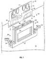
- FIG. 7is an in isometric view of an alternate form of the invention for use with a prior art modular component receiving arrangement.
- FIG. 8is a partial section view taken along line 8 — 8 in FIG. 7 showing the alternate form of invention shown in FIG. 7 as connected in an operating position with a prior art modular component receiving arrangement.
- a modular component receiving apparatus or structure 10is adapted to be mounted on a computer system motherboard 11 or similar structure.
- Receiving structure 10is particularly adapted for use in receiving a memory module 12 .
- Memory module 12includes a suitable substrate 14 on which is mounted one or more individually packaged memory circuit chips 15 .
- Module 12also includes a lower edge 19 having a contact structure 16 for making electrical contact with receiving structure 10 as will be described below.
- Memory module 12further includes an upper or the distal edge 17 and may further include shoulder features 18 which may be used to help retain the module in the desired installed position in receiving structure 10 as will be described below.
- a receiving structureadapted to receive and inline memory module such as memory module 12
- a receiving structure according to inventionis not limited to use with memory modules. Rather, the modular component receiving structure according to the invention may be used with substantially any other modular electronic components included in computer systems and other electronic systems.
- Receiving structure 10includes a connector shown generally at reference numeral 20 .
- Connector 20is adapted to operatively connect with contact structure 16 on memory module 12 when the module is in an installed position in receiving structure 10 . This installed position will be described below with particular reference to FIG. 5 .
- connector 20includes an elongated slot wide enough to receive the lower edge 19 of module 12 .
- An electrode structureis included with in connector 20 for making electrical contact with the various contact elements formed on contact structure 16 .
- These electronic elements of connector 20are well-known in the field and are omitted from the drawings so as not to the obscure the invention in unnecessary detail. However, it will be appreciated that the electrodes within connector 20 lead to an arrangement of pins 21 on a lower surface of receiving structure 10 , and that these pins are preferably used to mount the receiving structure 10 on system motherboard 11 .
- a locking arrangementis preferably associated with the lower portion of receiving structure 10 .
- the illustrated locking arrangementincludes two locking members 24 .
- One locking member 24is provided at each end of receiving structure 10 .
- Each locking member 24is adapted to pivot between an unlocked position shown in FIGS. 1 and 2 and a locked position shown in phantom in FIG. 2 .
- each locking member 24is adapted to make contact with one shoulder feature 18 on memory module 12 when the memory module is in the installed position and the respective locking member is pivoted to the locked position. This contact between the locking member 24 and shoulder feature 18 helps to retain memory module 12 securely in the installed position.
- receiving structure 10includes a guide structure 25 having a guide opening 26 .
- Guide opening 26is aligned with connector 20 so that module 12 may extend through the guide opening to connector 20 .
- guide opening 26may include insets 27 .
- one or more circulation openings 30may be included in guide structure 25 to allow air to circulate freely over chips 15 when module 12 is in the installed position.
- An upper portion of the guide structure 25is adapted to cover or enclose the distal edge 17 of memory module 12 when the module is in the installed position.
- guide structure 25By “covering” or “enclosing” distal edge 17 of module 12 , it is meant that the upper portion of guide structure 25 lies adjacent to the distal edge, blocking access to the distal edge of the module.
- guide structure 25also includes access features at both ends of the structure.
- the first access featureis shown generally at reference to 28 while a second access feature is shown generally at reference numeral 29 . As shown particularly in FIGS. 4 and 5, access features 28 and 29 leave a portion of module 12 exposed when the module is received in both an initial position and the installed position.
- the upper portion of guide structure 25includes a drive opening 32 .
- Drive opening 32has a longitudinal axis A extending generally perpendicular to the longitudinal dimension L of guide opening 26 .
- drive opening 32is threaded about its longitudinal axis L.
- An edge protection element 34is shown in FIG. 6, and is adapted to the received within drive opening 32 .
- Edge protection element 34preferably includes an external thread 35 which is complementary to the thread of drive opening 32 .
- a engagement feature 36is included on one end of edge protection element 34 for use in removing the edge protection element from drive opening 32 as will be discussed below.
- Receiving structure 10 and edge protection element 34may be formed from any suitable material. Suitable materials for the guide structure portion of receiving structure 10 include various rigid plastics. Edge protection element 34 is preferably formed from a low friction plastic material such as nylon. Alternatively, edge protection element 34 may include a plastic lower tip or a lower tip and drive portion which may rotate with respect to the lower tip (not shown).
- memory module 12is adapted to be inserted into the guide opening 26 defined in guide structure 25 .
- Memory module 12is first inserted into an initial position in which contact structure 16 resides adjacent to connector 20 . In this position, only the ends of memory module 12 are exposed. The bulk of distal edge 17 remains covered or enclosed in the upper portion of guide structure 25 . Leaving the ends a module 12 exposed in this fashion encourages and practically requires that the installer hold the memory module by the ends while inserting the module into the initial position in guide opening 26 . Thus, it is difficult for the installer to hold module 12 incorrectly while placing the module in the initial position.
- a drive element 38(shown in phantom lines in FIG. 5 and having a thread complementary to the thread of drive opening 32 ) may be threaded into the drive opening until an end of drive element 38 contacts distal edge 17 of module 12 .
- threading the drive elementfurther causes the element to impart a downward force on module 12 generally in the direction shown at arrow F in FIG. 5 .
- the force the installer applies to drive element 38is a simple rotational force to thread the drive element into drive opening 32 .
- the installerneed not apply a downward force in direction F.
- the downward, installation force F on module 12is generated as drive element 38 threads further into the threaded drive opening 32 and is actually applied from guide structure 25 .
- the installation forcemay be applied indirectly through edge protection element 34 shown in FIG. 6 .
- the installerinserts edge protection element 34 into drive opening 32 and then threads drive element 38 into the drive opening 32 above the edge protection element 34 .
- Drive element 38may then be threaded further into drive opening 32 to push or thread edge protection element 34 against distal edge 17 of module 12 and thus apply the installation force F to press module 12 into the installed position shown in FIG. 5 .
- edge protection element 34includes an unthreaded tip which may rotate with respect a threaded drive section, the installation force is applied without any rotating friction or wear against distal edge 17 .
- the preferred edge protection element 34 shown in FIG. 6may be removed only with the aid of a special tool (not shown).
- a tool adapted to mate with engagement feature 36is inserted into drive opening 32 and rotated in reverse to back the edge protection element out of the threaded drive opening.
- the installermay grasp module 12 by the ends exposed by access features 28 and 29 , and then pull the module from the installed position.
- FIGS. 7 and 8show a form of the invention for use with a prior part modular component receiving structure.
- this form of the inventionis illustrated in connection with a prior art memory module socket 42 which has been installed on a system motherboard 43 as shown in FIG. 8 .
- This form of the inventionincludes a guide structure 45 adapted to connect to the prior art socket structure 42 in an operating position shown in FIG. 8 .
- guide structure 45includes lateral extensions 47 which are adapted to extend to a bottom edge 48 of socket structure 42 .
- An angled feature 49 at the bottom of each lateral extension 47snaps over bottom edge 48 and provides a secure connection between guide structure 45 and prior art socket structure 42 .
- guide structure 45includes a guide opening 46 .
- This guide opening 46is oriented in guide structure 45 so as to align with socket 42 when the guide structure is in the operating position shown in FIG. 8 .
- the upper portion of guide structure 45corresponds to the upper portion shown in FIGS. 1 through 5.
- the length of guide structure 45is relatively shorter than the length of socket 42 . This leaves the ends of a memory module received in the structure 45 exposed similarly to the areas of the module 12 exposed by access features 28 and 29 shown in FIGS. 2, 4 , and 5 and described above.
- the alternative guide structure 45 shown in FIGS. 7 and 8also includes a drive opening 52 corresponding to the drive opening 32 shown in FIGS. 1 through 5.
- Drive opening 52is threaded as previously described with reference to drive opening 32 and provides the identical function as that previously described drive opening.
- Edge protection elementssuch has the edge protection element 34 shown in FIG. 6 may be used with the form of invention shown FIGS. 7 and 8.
Landscapes
- Details Of Connecting Devices For Male And Female Coupling (AREA)
Abstract
Description
Claims (21)
Priority Applications (1)
| Application Number | Priority Date | Filing Date | Title |
|---|---|---|---|
| US09/519,697US6312279B1 (en) | 2000-03-07 | 2000-03-07 | Modular component receiving apparatus and method for installing modular components |
Applications Claiming Priority (1)
| Application Number | Priority Date | Filing Date | Title |
|---|---|---|---|
| US09/519,697US6312279B1 (en) | 2000-03-07 | 2000-03-07 | Modular component receiving apparatus and method for installing modular components |
Publications (1)
| Publication Number | Publication Date |
|---|---|
| US6312279B1true US6312279B1 (en) | 2001-11-06 |
Family
ID=24069390
Family Applications (1)
| Application Number | Title | Priority Date | Filing Date |
|---|---|---|---|
| US09/519,697Expired - LifetimeUS6312279B1 (en) | 2000-03-07 | 2000-03-07 | Modular component receiving apparatus and method for installing modular components |
Country Status (1)
| Country | Link |
|---|---|
| US (1) | US6312279B1 (en) |
Cited By (10)
| Publication number | Priority date | Publication date | Assignee | Title |
|---|---|---|---|---|
| USD488135S1 (en) | 2001-11-21 | 2004-04-06 | Camden Electronics Ltd. | Set of modules for a modular mount for circuit boards |
| US20060128200A1 (en)* | 2004-12-10 | 2006-06-15 | Technology Advancement Group, Inc. | Device for securing a circuit board to a socket |
| US20080090446A1 (en)* | 2006-10-17 | 2008-04-17 | Mark Lamont | Peripheral device locking arrangement |
| US20080153336A1 (en)* | 2004-12-10 | 2008-06-26 | Technology Advancement Group, Inc. | Method and device for securing a circuit board to a computer assembly |
| US20090088003A1 (en)* | 2007-09-28 | 2009-04-02 | David Stanley Szczesny | Electrical connector with protective member |
| US20130309892A1 (en)* | 2012-05-17 | 2013-11-21 | Kunshan Jiahua Electronics Co., Ltd. | Card Edge Connector with Improved Locking Arm |
| US9853381B1 (en)* | 2016-08-31 | 2017-12-26 | Germane Systems, Llc | Apparatus and method for mounting a circuit board in a connector socket |
| US10109941B1 (en)* | 2017-06-30 | 2018-10-23 | Intel Corporation | Stepped slot connector to enable low height platforms |
| US20190036285A1 (en)* | 2017-07-27 | 2019-01-31 | Innodisk Corporation | High-speed transmission connector and application device thereof |
| US10320100B2 (en)* | 2017-10-06 | 2019-06-11 | Te Connectivity Corporation | Card edge connector assembly |
Citations (11)
| Publication number | Priority date | Publication date | Assignee | Title |
|---|---|---|---|---|
| US4946403A (en) | 1989-08-24 | 1990-08-07 | Amp Incorporated | Low insertion force circuit panel socket |
| US5026297A (en) | 1990-06-28 | 1991-06-25 | Molex Incorporated | Electrical socket assembly for single in-line circuit package |
| US5137462A (en)* | 1991-08-13 | 1992-08-11 | Amp Incorporated | Adapter for stacking connector assembly |
| US5199895A (en) | 1992-02-04 | 1993-04-06 | Chang Lien Ker | Low insertion force, self-locking connecting apparatus for electrically connecting memory modules to a printed circuit board |
| US5259781A (en)* | 1992-11-18 | 1993-11-09 | International Business Machines Corporation | Electrical connector alignment and actuation assembly |
| US5632640A (en) | 1995-01-20 | 1997-05-27 | Molex Incorporated | Insert and rotate connector with improved latching means |
| US5650917A (en)* | 1996-10-09 | 1997-07-22 | Hsu; Fu-Yu | CPU card mounting structure |
| US5660557A (en)* | 1995-12-29 | 1997-08-26 | Berg Technology, Inc. | Shroud latch for electrical connectors |
| US5863213A (en) | 1996-10-30 | 1999-01-26 | The Whitaker Corporation | Memory card connector and adapter therefor |
| US6030251A (en)* | 1998-02-17 | 2000-02-29 | Intel Corporation | Keyed interlock and mechanical alignment integrated mechanical retention features for PC system |
| US6126471A (en)* | 1999-04-16 | 2000-10-03 | Hon Hai Precision Ind. Co., Ltd. | Retention mechanism |
- 2000
- 2000-03-07USUS09/519,697patent/US6312279B1/ennot_activeExpired - Lifetime
Patent Citations (11)
| Publication number | Priority date | Publication date | Assignee | Title |
|---|---|---|---|---|
| US4946403A (en) | 1989-08-24 | 1990-08-07 | Amp Incorporated | Low insertion force circuit panel socket |
| US5026297A (en) | 1990-06-28 | 1991-06-25 | Molex Incorporated | Electrical socket assembly for single in-line circuit package |
| US5137462A (en)* | 1991-08-13 | 1992-08-11 | Amp Incorporated | Adapter for stacking connector assembly |
| US5199895A (en) | 1992-02-04 | 1993-04-06 | Chang Lien Ker | Low insertion force, self-locking connecting apparatus for electrically connecting memory modules to a printed circuit board |
| US5259781A (en)* | 1992-11-18 | 1993-11-09 | International Business Machines Corporation | Electrical connector alignment and actuation assembly |
| US5632640A (en) | 1995-01-20 | 1997-05-27 | Molex Incorporated | Insert and rotate connector with improved latching means |
| US5660557A (en)* | 1995-12-29 | 1997-08-26 | Berg Technology, Inc. | Shroud latch for electrical connectors |
| US5650917A (en)* | 1996-10-09 | 1997-07-22 | Hsu; Fu-Yu | CPU card mounting structure |
| US5863213A (en) | 1996-10-30 | 1999-01-26 | The Whitaker Corporation | Memory card connector and adapter therefor |
| US6030251A (en)* | 1998-02-17 | 2000-02-29 | Intel Corporation | Keyed interlock and mechanical alignment integrated mechanical retention features for PC system |
| US6126471A (en)* | 1999-04-16 | 2000-10-03 | Hon Hai Precision Ind. Co., Ltd. | Retention mechanism |
Cited By (19)
| Publication number | Priority date | Publication date | Assignee | Title |
|---|---|---|---|---|
| USD488135S1 (en) | 2001-11-21 | 2004-04-06 | Camden Electronics Ltd. | Set of modules for a modular mount for circuit boards |
| US20060128200A1 (en)* | 2004-12-10 | 2006-06-15 | Technology Advancement Group, Inc. | Device for securing a circuit board to a socket |
| US7310237B2 (en)* | 2004-12-10 | 2007-12-18 | Technology Advancement Group, Inc. | Device for securing a circuit board to a socket |
| US20080153336A1 (en)* | 2004-12-10 | 2008-06-26 | Technology Advancement Group, Inc. | Method and device for securing a circuit board to a computer assembly |
| US20080153326A1 (en)* | 2004-12-10 | 2008-06-26 | Technology Advancement Group, Inc. | Method for securing a circuit board to a socket |
| US8011088B2 (en) | 2004-12-10 | 2011-09-06 | Technology Advancement Group, Inc. | Method for securing a circuit board to a socket |
| US7556519B2 (en) | 2004-12-10 | 2009-07-07 | Technology Advancement Group, Inc. | Method and device for securing a circuit board to a computer assembly |
| US20080090446A1 (en)* | 2006-10-17 | 2008-04-17 | Mark Lamont | Peripheral device locking arrangement |
| US7699644B2 (en)* | 2007-09-28 | 2010-04-20 | Tyco Electronics Corporation | Electrical connector with protective member |
| US20090088003A1 (en)* | 2007-09-28 | 2009-04-02 | David Stanley Szczesny | Electrical connector with protective member |
| US20130309892A1 (en)* | 2012-05-17 | 2013-11-21 | Kunshan Jiahua Electronics Co., Ltd. | Card Edge Connector with Improved Locking Arm |
| US8851916B2 (en)* | 2012-05-17 | 2014-10-07 | Kunshan Jiahua Electronics Co., Ltd. | Card edge connector with improved locking arm |
| US9853381B1 (en)* | 2016-08-31 | 2017-12-26 | Germane Systems, Llc | Apparatus and method for mounting a circuit board in a connector socket |
| US10109941B1 (en)* | 2017-06-30 | 2018-10-23 | Intel Corporation | Stepped slot connector to enable low height platforms |
| EP3422483A1 (en)* | 2017-06-30 | 2019-01-02 | INTEL Corporation | Stepped slot connector to enable low height platforms |
| CN109216975A (en)* | 2017-06-30 | 2019-01-15 | 英特尔公司 | For enabling the staged slot connector of low clearance platform |
| CN109216975B (en)* | 2017-06-30 | 2025-09-23 | 英特尔公司 | Stepped slot connector to enable low-profile platforms |
| US20190036285A1 (en)* | 2017-07-27 | 2019-01-31 | Innodisk Corporation | High-speed transmission connector and application device thereof |
| US10320100B2 (en)* | 2017-10-06 | 2019-06-11 | Te Connectivity Corporation | Card edge connector assembly |
Similar Documents
| Publication | Publication Date | Title |
|---|---|---|
| US7462067B1 (en) | Cable-to-cable panel mount power connector | |
| US6735091B2 (en) | Cardguide retainer | |
| US4873761A (en) | Insertion/extraction tool | |
| US5221209A (en) | Modular pad array interface | |
| US6312279B1 (en) | Modular component receiving apparatus and method for installing modular components | |
| KR20020002421A (en) | Memory module with offset notches for improved insertion and stability and memory module connector | |
| JP3306831B2 (en) | Small card docking connector | |
| EP0676836B1 (en) | Electrical connector assembly including suction platform for facilitating picking | |
| US6618253B1 (en) | Retainer device for heat sink assembly | |
| US6821138B2 (en) | ZIF socket connector having means for preventing CPU mounted on the connector from deformation due to a clamping force acting thereon | |
| EP0443493A2 (en) | Electrical connector with module extraction apparatus | |
| EP0622868A2 (en) | Data communications outlet kit | |
| US4538870A (en) | Electrical connectors | |
| US6545877B1 (en) | Card retaining module for expansion slots | |
| US20060185159A1 (en) | Memory card insertion tool | |
| EP0427560A2 (en) | Removing a multi-pin component installed in sockets on a circuit board | |
| TW382839B (en) | Method of fabricating a receptacle connector for an IC card | |
| US6683251B1 (en) | Pressure plate for switch or receptacle | |
| US5232375A (en) | Parallel latching device for connectors | |
| US5348489A (en) | Socket assembly for an integrated circuit chip | |
| US6695634B1 (en) | Method and system for coupling circuit boards in a parallel configuration | |
| CA1123503A (en) | Latching lever for printed circuit boards | |
| US20030013350A1 (en) | Coupler for banana plug connectors and coupled banana plug connectors | |
| US5440803A (en) | Integrated circuit extraction tool | |
| JP2001351747A (en) | Multicore connector |
Legal Events
| Date | Code | Title | Description |
|---|---|---|---|
| AS | Assignment | Owner name:DELL PRODUCTS L.P., TEXAS Free format text:ASSIGNMENT OF ASSIGNORS INTEREST;ASSIGNORS:RACHUI, ROY;MANLEY, MARK;SLOAN, ROBERT C.;AND OTHERS;REEL/FRAME:010633/0314;SIGNING DATES FROM 20000306 TO 20000307 | |
| STCF | Information on status: patent grant | Free format text:PATENTED CASE | |
| FEPP | Fee payment procedure | Free format text:PAYOR NUMBER ASSIGNED (ORIGINAL EVENT CODE: ASPN); ENTITY STATUS OF PATENT OWNER: LARGE ENTITY | |
| FEPP | Fee payment procedure | Free format text:PAYER NUMBER DE-ASSIGNED (ORIGINAL EVENT CODE: RMPN); ENTITY STATUS OF PATENT OWNER: LARGE ENTITY Free format text:PAYOR NUMBER ASSIGNED (ORIGINAL EVENT CODE: ASPN); ENTITY STATUS OF PATENT OWNER: LARGE ENTITY | |
| FPAY | Fee payment | Year of fee payment:4 | |
| FPAY | Fee payment | Year of fee payment:8 | |
| FPAY | Fee payment | Year of fee payment:12 | |
| AS | Assignment | Owner name:BANK OF AMERICA, N.A., AS ADMINISTRATIVE AGENT, TE Free format text:PATENT SECURITY AGREEMENT (ABL);ASSIGNORS:DELL INC.;APPASSURE SOFTWARE, INC.;ASAP SOFTWARE EXPRESS, INC.;AND OTHERS;REEL/FRAME:031898/0001 Effective date:20131029 Owner name:BANK OF AMERICA, N.A., AS ADMINISTRATIVE AGENT, TEXAS Free format text:PATENT SECURITY AGREEMENT (ABL);ASSIGNORS:DELL INC.;APPASSURE SOFTWARE, INC.;ASAP SOFTWARE EXPRESS, INC.;AND OTHERS;REEL/FRAME:031898/0001 Effective date:20131029 Owner name:BANK OF AMERICA, N.A., AS COLLATERAL AGENT, NORTH CAROLINA Free format text:PATENT SECURITY AGREEMENT (TERM LOAN);ASSIGNORS:DELL INC.;APPASSURE SOFTWARE, INC.;ASAP SOFTWARE EXPRESS, INC.;AND OTHERS;REEL/FRAME:031899/0261 Effective date:20131029 Owner name:BANK OF NEW YORK MELLON TRUST COMPANY, N.A., AS FIRST LIEN COLLATERAL AGENT, TEXAS Free format text:PATENT SECURITY AGREEMENT (NOTES);ASSIGNORS:APPASSURE SOFTWARE, INC.;ASAP SOFTWARE EXPRESS, INC.;BOOMI, INC.;AND OTHERS;REEL/FRAME:031897/0348 Effective date:20131029 Owner name:BANK OF AMERICA, N.A., AS COLLATERAL AGENT, NORTH Free format text:PATENT SECURITY AGREEMENT (TERM LOAN);ASSIGNORS:DELL INC.;APPASSURE SOFTWARE, INC.;ASAP SOFTWARE EXPRESS, INC.;AND OTHERS;REEL/FRAME:031899/0261 Effective date:20131029 Owner name:BANK OF NEW YORK MELLON TRUST COMPANY, N.A., AS FI Free format text:PATENT SECURITY AGREEMENT (NOTES);ASSIGNORS:APPASSURE SOFTWARE, INC.;ASAP SOFTWARE EXPRESS, INC.;BOOMI, INC.;AND OTHERS;REEL/FRAME:031897/0348 Effective date:20131029 | |
| AS | Assignment | Owner name:DELL INC., TEXAS Free format text:RELEASE BY SECURED PARTY;ASSIGNOR:BANK OF AMERICA, N.A., AS ADMINISTRATIVE AGENT;REEL/FRAME:040065/0216 Effective date:20160907 Owner name:DELL MARKETING L.P., TEXAS Free format text:RELEASE BY SECURED PARTY;ASSIGNOR:BANK OF AMERICA, N.A., AS ADMINISTRATIVE AGENT;REEL/FRAME:040065/0216 Effective date:20160907 Owner name:PEROT SYSTEMS CORPORATION, TEXAS Free format text:RELEASE BY SECURED PARTY;ASSIGNOR:BANK OF AMERICA, N.A., AS ADMINISTRATIVE AGENT;REEL/FRAME:040065/0216 Effective date:20160907 Owner name:DELL PRODUCTS L.P., TEXAS Free format text:RELEASE BY SECURED PARTY;ASSIGNOR:BANK OF AMERICA, N.A., AS ADMINISTRATIVE AGENT;REEL/FRAME:040065/0216 Effective date:20160907 Owner name:CREDANT TECHNOLOGIES, INC., TEXAS Free format text:RELEASE BY SECURED PARTY;ASSIGNOR:BANK OF AMERICA, N.A., AS ADMINISTRATIVE AGENT;REEL/FRAME:040065/0216 Effective date:20160907 Owner name:APPASSURE SOFTWARE, INC., VIRGINIA Free format text:RELEASE BY SECURED PARTY;ASSIGNOR:BANK OF AMERICA, N.A., AS ADMINISTRATIVE AGENT;REEL/FRAME:040065/0216 Effective date:20160907 Owner name:DELL SOFTWARE INC., CALIFORNIA Free format text:RELEASE BY SECURED PARTY;ASSIGNOR:BANK OF AMERICA, N.A., AS ADMINISTRATIVE AGENT;REEL/FRAME:040065/0216 Effective date:20160907 Owner name:ASAP SOFTWARE EXPRESS, INC., ILLINOIS Free format text:RELEASE BY SECURED PARTY;ASSIGNOR:BANK OF AMERICA, N.A., AS ADMINISTRATIVE AGENT;REEL/FRAME:040065/0216 Effective date:20160907 Owner name:SECUREWORKS, INC., GEORGIA Free format text:RELEASE BY SECURED PARTY;ASSIGNOR:BANK OF AMERICA, N.A., AS ADMINISTRATIVE AGENT;REEL/FRAME:040065/0216 Effective date:20160907 Owner name:DELL USA L.P., TEXAS Free format text:RELEASE BY SECURED PARTY;ASSIGNOR:BANK OF AMERICA, N.A., AS ADMINISTRATIVE AGENT;REEL/FRAME:040065/0216 Effective date:20160907 Owner name:WYSE TECHNOLOGY L.L.C., CALIFORNIA Free format text:RELEASE BY SECURED PARTY;ASSIGNOR:BANK OF AMERICA, N.A., AS ADMINISTRATIVE AGENT;REEL/FRAME:040065/0216 Effective date:20160907 Owner name:COMPELLANT TECHNOLOGIES, INC., MINNESOTA Free format text:RELEASE BY SECURED PARTY;ASSIGNOR:BANK OF AMERICA, N.A., AS ADMINISTRATIVE AGENT;REEL/FRAME:040065/0216 Effective date:20160907 Owner name:FORCE10 NETWORKS, INC., CALIFORNIA Free format text:RELEASE BY SECURED PARTY;ASSIGNOR:BANK OF AMERICA, N.A., AS ADMINISTRATIVE AGENT;REEL/FRAME:040065/0216 Effective date:20160907 | |
| AS | Assignment | Owner name:CREDANT TECHNOLOGIES, INC., TEXAS Free format text:RELEASE BY SECURED PARTY;ASSIGNOR:BANK OF AMERICA, N.A., AS COLLATERAL AGENT;REEL/FRAME:040040/0001 Effective date:20160907 Owner name:COMPELLENT TECHNOLOGIES, INC., MINNESOTA Free format text:RELEASE BY SECURED PARTY;ASSIGNOR:BANK OF AMERICA, N.A., AS COLLATERAL AGENT;REEL/FRAME:040040/0001 Effective date:20160907 Owner name:DELL USA L.P., TEXAS Free format text:RELEASE BY SECURED PARTY;ASSIGNOR:BANK OF AMERICA, N.A., AS COLLATERAL AGENT;REEL/FRAME:040040/0001 Effective date:20160907 Owner name:ASAP SOFTWARE EXPRESS, INC., ILLINOIS Free format text:RELEASE BY SECURED PARTY;ASSIGNOR:BANK OF AMERICA, N.A., AS COLLATERAL AGENT;REEL/FRAME:040040/0001 Effective date:20160907 Owner name:DELL SOFTWARE INC., CALIFORNIA Free format text:RELEASE BY SECURED PARTY;ASSIGNOR:BANK OF AMERICA, N.A., AS COLLATERAL AGENT;REEL/FRAME:040040/0001 Effective date:20160907 Owner name:WYSE TECHNOLOGY L.L.C., CALIFORNIA Free format text:RELEASE BY SECURED PARTY;ASSIGNOR:BANK OF AMERICA, N.A., AS COLLATERAL AGENT;REEL/FRAME:040040/0001 Effective date:20160907 Owner name:APPASSURE SOFTWARE, INC., VIRGINIA Free format text:RELEASE BY SECURED PARTY;ASSIGNOR:BANK OF AMERICA, N.A., AS COLLATERAL AGENT;REEL/FRAME:040040/0001 Effective date:20160907 Owner name:PEROT SYSTEMS CORPORATION, TEXAS Free format text:RELEASE BY SECURED PARTY;ASSIGNOR:BANK OF AMERICA, N.A., AS COLLATERAL AGENT;REEL/FRAME:040040/0001 Effective date:20160907 Owner name:DELL PRODUCTS L.P., TEXAS Free format text:RELEASE BY SECURED PARTY;ASSIGNOR:BANK OF AMERICA, N.A., AS COLLATERAL AGENT;REEL/FRAME:040040/0001 Effective date:20160907 Owner name:DELL MARKETING L.P., TEXAS Free format text:RELEASE BY SECURED PARTY;ASSIGNOR:BANK OF AMERICA, N.A., AS COLLATERAL AGENT;REEL/FRAME:040040/0001 Effective date:20160907 Owner name:DELL INC., TEXAS Free format text:RELEASE BY SECURED PARTY;ASSIGNOR:BANK OF AMERICA, N.A., AS COLLATERAL AGENT;REEL/FRAME:040040/0001 Effective date:20160907 Owner name:SECUREWORKS, INC., GEORGIA Free format text:RELEASE BY SECURED PARTY;ASSIGNOR:BANK OF AMERICA, N.A., AS COLLATERAL AGENT;REEL/FRAME:040040/0001 Effective date:20160907 Owner name:FORCE10 NETWORKS, INC., CALIFORNIA Free format text:RELEASE BY SECURED PARTY;ASSIGNOR:BANK OF AMERICA, N.A., AS COLLATERAL AGENT;REEL/FRAME:040040/0001 Effective date:20160907 Owner name:DELL MARKETING L.P., TEXAS Free format text:RELEASE BY SECURED PARTY;ASSIGNOR:BANK OF NEW YORK MELLON TRUST COMPANY, N.A., AS COLLATERAL AGENT;REEL/FRAME:040065/0618 Effective date:20160907 Owner name:FORCE10 NETWORKS, INC., CALIFORNIA Free format text:RELEASE BY SECURED PARTY;ASSIGNOR:BANK OF NEW YORK MELLON TRUST COMPANY, N.A., AS COLLATERAL AGENT;REEL/FRAME:040065/0618 Effective date:20160907 Owner name:DELL INC., TEXAS Free format text:RELEASE BY SECURED PARTY;ASSIGNOR:BANK OF NEW YORK MELLON TRUST COMPANY, N.A., AS COLLATERAL AGENT;REEL/FRAME:040065/0618 Effective date:20160907 Owner name:DELL USA L.P., TEXAS Free format text:RELEASE BY SECURED PARTY;ASSIGNOR:BANK OF NEW YORK MELLON TRUST COMPANY, N.A., AS COLLATERAL AGENT;REEL/FRAME:040065/0618 Effective date:20160907 Owner name:SECUREWORKS, INC., GEORGIA Free format text:RELEASE BY SECURED PARTY;ASSIGNOR:BANK OF NEW YORK MELLON TRUST COMPANY, N.A., AS COLLATERAL AGENT;REEL/FRAME:040065/0618 Effective date:20160907 Owner name:DELL SOFTWARE INC., CALIFORNIA Free format text:RELEASE BY SECURED PARTY;ASSIGNOR:BANK OF NEW YORK MELLON TRUST COMPANY, N.A., AS COLLATERAL AGENT;REEL/FRAME:040065/0618 Effective date:20160907 Owner name:ASAP SOFTWARE EXPRESS, INC., ILLINOIS Free format text:RELEASE BY SECURED PARTY;ASSIGNOR:BANK OF NEW YORK MELLON TRUST COMPANY, N.A., AS COLLATERAL AGENT;REEL/FRAME:040065/0618 Effective date:20160907 Owner name:WYSE TECHNOLOGY L.L.C., CALIFORNIA Free format text:RELEASE BY SECURED PARTY;ASSIGNOR:BANK OF NEW YORK MELLON TRUST COMPANY, N.A., AS COLLATERAL AGENT;REEL/FRAME:040065/0618 Effective date:20160907 Owner name:PEROT SYSTEMS CORPORATION, TEXAS Free format text:RELEASE BY SECURED PARTY;ASSIGNOR:BANK OF NEW YORK MELLON TRUST COMPANY, N.A., AS COLLATERAL AGENT;REEL/FRAME:040065/0618 Effective date:20160907 Owner name:COMPELLENT TECHNOLOGIES, INC., MINNESOTA Free format text:RELEASE BY SECURED PARTY;ASSIGNOR:BANK OF NEW YORK MELLON TRUST COMPANY, N.A., AS COLLATERAL AGENT;REEL/FRAME:040065/0618 Effective date:20160907 Owner name:APPASSURE SOFTWARE, INC., VIRGINIA Free format text:RELEASE BY SECURED PARTY;ASSIGNOR:BANK OF NEW YORK MELLON TRUST COMPANY, N.A., AS COLLATERAL AGENT;REEL/FRAME:040065/0618 Effective date:20160907 Owner name:CREDANT TECHNOLOGIES, INC., TEXAS Free format text:RELEASE BY SECURED PARTY;ASSIGNOR:BANK OF NEW YORK MELLON TRUST COMPANY, N.A., AS COLLATERAL AGENT;REEL/FRAME:040065/0618 Effective date:20160907 Owner name:DELL PRODUCTS L.P., TEXAS Free format text:RELEASE BY SECURED PARTY;ASSIGNOR:BANK OF NEW YORK MELLON TRUST COMPANY, N.A., AS COLLATERAL AGENT;REEL/FRAME:040065/0618 Effective date:20160907 | |
| AS | Assignment | Owner name:CREDIT SUISSE AG, CAYMAN ISLANDS BRANCH, AS COLLATERAL AGENT, NORTH CAROLINA Free format text:SECURITY AGREEMENT;ASSIGNORS:ASAP SOFTWARE EXPRESS, INC.;AVENTAIL LLC;CREDANT TECHNOLOGIES, INC.;AND OTHERS;REEL/FRAME:040134/0001 Effective date:20160907 Owner name:THE BANK OF NEW YORK MELLON TRUST COMPANY, N.A., AS NOTES COLLATERAL AGENT, TEXAS Free format text:SECURITY AGREEMENT;ASSIGNORS:ASAP SOFTWARE EXPRESS, INC.;AVENTAIL LLC;CREDANT TECHNOLOGIES, INC.;AND OTHERS;REEL/FRAME:040136/0001 Effective date:20160907 Owner name:CREDIT SUISSE AG, CAYMAN ISLANDS BRANCH, AS COLLAT Free format text:SECURITY AGREEMENT;ASSIGNORS:ASAP SOFTWARE EXPRESS, INC.;AVENTAIL LLC;CREDANT TECHNOLOGIES, INC.;AND OTHERS;REEL/FRAME:040134/0001 Effective date:20160907 Owner name:THE BANK OF NEW YORK MELLON TRUST COMPANY, N.A., A Free format text:SECURITY AGREEMENT;ASSIGNORS:ASAP SOFTWARE EXPRESS, INC.;AVENTAIL LLC;CREDANT TECHNOLOGIES, INC.;AND OTHERS;REEL/FRAME:040136/0001 Effective date:20160907 | |
| AS | Assignment | Owner name:THE BANK OF NEW YORK MELLON TRUST COMPANY, N.A., T Free format text:SECURITY AGREEMENT;ASSIGNORS:CREDANT TECHNOLOGIES, INC.;DELL INTERNATIONAL L.L.C.;DELL MARKETING L.P.;AND OTHERS;REEL/FRAME:049452/0223 Effective date:20190320 Owner name:THE BANK OF NEW YORK MELLON TRUST COMPANY, N.A., TEXAS Free format text:SECURITY AGREEMENT;ASSIGNORS:CREDANT TECHNOLOGIES, INC.;DELL INTERNATIONAL L.L.C.;DELL MARKETING L.P.;AND OTHERS;REEL/FRAME:049452/0223 Effective date:20190320 | |
| AS | Assignment | Owner name:WYSE TECHNOLOGY L.L.C., CALIFORNIA Free format text:RELEASE BY SECURED PARTY;ASSIGNOR:CREDIT SUISSE AG, CAYMAN ISLANDS BRANCH;REEL/FRAME:058216/0001 Effective date:20211101 Owner name:SCALEIO LLC, MASSACHUSETTS Free format text:RELEASE BY SECURED PARTY;ASSIGNOR:CREDIT SUISSE AG, CAYMAN ISLANDS BRANCH;REEL/FRAME:058216/0001 Effective date:20211101 Owner name:MOZY, INC., WASHINGTON Free format text:RELEASE BY SECURED PARTY;ASSIGNOR:CREDIT SUISSE AG, CAYMAN ISLANDS BRANCH;REEL/FRAME:058216/0001 Effective date:20211101 Owner name:MAGINATICS LLC, CALIFORNIA Free format text:RELEASE BY SECURED PARTY;ASSIGNOR:CREDIT SUISSE AG, CAYMAN ISLANDS BRANCH;REEL/FRAME:058216/0001 Effective date:20211101 Owner name:FORCE10 NETWORKS, INC., CALIFORNIA Free format text:RELEASE BY SECURED PARTY;ASSIGNOR:CREDIT SUISSE AG, CAYMAN ISLANDS BRANCH;REEL/FRAME:058216/0001 Effective date:20211101 Owner name:EMC IP HOLDING COMPANY LLC, TEXAS Free format text:RELEASE BY SECURED PARTY;ASSIGNOR:CREDIT SUISSE AG, CAYMAN ISLANDS BRANCH;REEL/FRAME:058216/0001 Effective date:20211101 Owner name:EMC CORPORATION, MASSACHUSETTS Free format text:RELEASE BY SECURED PARTY;ASSIGNOR:CREDIT SUISSE AG, CAYMAN ISLANDS BRANCH;REEL/FRAME:058216/0001 Effective date:20211101 Owner name:DELL SYSTEMS CORPORATION, TEXAS Free format text:RELEASE BY SECURED PARTY;ASSIGNOR:CREDIT SUISSE AG, CAYMAN ISLANDS BRANCH;REEL/FRAME:058216/0001 Effective date:20211101 Owner name:DELL SOFTWARE INC., CALIFORNIA Free format text:RELEASE BY SECURED PARTY;ASSIGNOR:CREDIT SUISSE AG, CAYMAN ISLANDS BRANCH;REEL/FRAME:058216/0001 Effective date:20211101 Owner name:DELL PRODUCTS L.P., TEXAS Free format text:RELEASE BY SECURED PARTY;ASSIGNOR:CREDIT SUISSE AG, CAYMAN ISLANDS BRANCH;REEL/FRAME:058216/0001 Effective date:20211101 Owner name:DELL MARKETING L.P., TEXAS Free format text:RELEASE BY SECURED PARTY;ASSIGNOR:CREDIT SUISSE AG, CAYMAN ISLANDS BRANCH;REEL/FRAME:058216/0001 Effective date:20211101 Owner name:DELL INTERNATIONAL, L.L.C., TEXAS Free format text:RELEASE BY SECURED PARTY;ASSIGNOR:CREDIT SUISSE AG, CAYMAN ISLANDS BRANCH;REEL/FRAME:058216/0001 Effective date:20211101 Owner name:DELL USA L.P., TEXAS Free format text:RELEASE BY SECURED PARTY;ASSIGNOR:CREDIT SUISSE AG, CAYMAN ISLANDS BRANCH;REEL/FRAME:058216/0001 Effective date:20211101 Owner name:CREDANT TECHNOLOGIES, INC., TEXAS Free format text:RELEASE BY SECURED PARTY;ASSIGNOR:CREDIT SUISSE AG, CAYMAN ISLANDS BRANCH;REEL/FRAME:058216/0001 Effective date:20211101 Owner name:AVENTAIL LLC, CALIFORNIA Free format text:RELEASE BY SECURED PARTY;ASSIGNOR:CREDIT SUISSE AG, CAYMAN ISLANDS BRANCH;REEL/FRAME:058216/0001 Effective date:20211101 Owner name:ASAP SOFTWARE EXPRESS, INC., ILLINOIS Free format text:RELEASE BY SECURED PARTY;ASSIGNOR:CREDIT SUISSE AG, CAYMAN ISLANDS BRANCH;REEL/FRAME:058216/0001 Effective date:20211101 | |
| AS | Assignment | Owner name:SCALEIO LLC, MASSACHUSETTS Free format text:RELEASE OF SECURITY INTEREST IN PATENTS PREVIOUSLY RECORDED AT REEL/FRAME (040136/0001);ASSIGNOR:THE BANK OF NEW YORK MELLON TRUST COMPANY, N.A., AS NOTES COLLATERAL AGENT;REEL/FRAME:061324/0001 Effective date:20220329 Owner name:EMC IP HOLDING COMPANY LLC (ON BEHALF OF ITSELF AND AS SUCCESSOR-IN-INTEREST TO MOZY, INC.), TEXAS Free format text:RELEASE OF SECURITY INTEREST IN PATENTS PREVIOUSLY RECORDED AT REEL/FRAME (040136/0001);ASSIGNOR:THE BANK OF NEW YORK MELLON TRUST COMPANY, N.A., AS NOTES COLLATERAL AGENT;REEL/FRAME:061324/0001 Effective date:20220329 Owner name:EMC CORPORATION (ON BEHALF OF ITSELF AND AS SUCCESSOR-IN-INTEREST TO MAGINATICS LLC), MASSACHUSETTS Free format text:RELEASE OF SECURITY INTEREST IN PATENTS PREVIOUSLY RECORDED AT REEL/FRAME (040136/0001);ASSIGNOR:THE BANK OF NEW YORK MELLON TRUST COMPANY, N.A., AS NOTES COLLATERAL AGENT;REEL/FRAME:061324/0001 Effective date:20220329 Owner name:DELL MARKETING CORPORATION (SUCCESSOR-IN-INTEREST TO FORCE10 NETWORKS, INC. AND WYSE TECHNOLOGY L.L.C.), TEXAS Free format text:RELEASE OF SECURITY INTEREST IN PATENTS PREVIOUSLY RECORDED AT REEL/FRAME (040136/0001);ASSIGNOR:THE BANK OF NEW YORK MELLON TRUST COMPANY, N.A., AS NOTES COLLATERAL AGENT;REEL/FRAME:061324/0001 Effective date:20220329 Owner name:DELL PRODUCTS L.P., TEXAS Free format text:RELEASE OF SECURITY INTEREST IN PATENTS PREVIOUSLY RECORDED AT REEL/FRAME (040136/0001);ASSIGNOR:THE BANK OF NEW YORK MELLON TRUST COMPANY, N.A., AS NOTES COLLATERAL AGENT;REEL/FRAME:061324/0001 Effective date:20220329 Owner name:DELL INTERNATIONAL L.L.C., TEXAS Free format text:RELEASE OF SECURITY INTEREST IN PATENTS PREVIOUSLY RECORDED AT REEL/FRAME (040136/0001);ASSIGNOR:THE BANK OF NEW YORK MELLON TRUST COMPANY, N.A., AS NOTES COLLATERAL AGENT;REEL/FRAME:061324/0001 Effective date:20220329 Owner name:DELL USA L.P., TEXAS Free format text:RELEASE OF SECURITY INTEREST IN PATENTS PREVIOUSLY RECORDED AT REEL/FRAME (040136/0001);ASSIGNOR:THE BANK OF NEW YORK MELLON TRUST COMPANY, N.A., AS NOTES COLLATERAL AGENT;REEL/FRAME:061324/0001 Effective date:20220329 Owner name:DELL MARKETING L.P. (ON BEHALF OF ITSELF AND AS SUCCESSOR-IN-INTEREST TO CREDANT TECHNOLOGIES, INC.), TEXAS Free format text:RELEASE OF SECURITY INTEREST IN PATENTS PREVIOUSLY RECORDED AT REEL/FRAME (040136/0001);ASSIGNOR:THE BANK OF NEW YORK MELLON TRUST COMPANY, N.A., AS NOTES COLLATERAL AGENT;REEL/FRAME:061324/0001 Effective date:20220329 Owner name:DELL MARKETING CORPORATION (SUCCESSOR-IN-INTEREST TO ASAP SOFTWARE EXPRESS, INC.), TEXAS Free format text:RELEASE OF SECURITY INTEREST IN PATENTS PREVIOUSLY RECORDED AT REEL/FRAME (040136/0001);ASSIGNOR:THE BANK OF NEW YORK MELLON TRUST COMPANY, N.A., AS NOTES COLLATERAL AGENT;REEL/FRAME:061324/0001 Effective date:20220329 | |
| AS | Assignment | Owner name:SCALEIO LLC, MASSACHUSETTS Free format text:RELEASE OF SECURITY INTEREST IN PATENTS PREVIOUSLY RECORDED AT REEL/FRAME (045455/0001);ASSIGNOR:THE BANK OF NEW YORK MELLON TRUST COMPANY, N.A., AS NOTES COLLATERAL AGENT;REEL/FRAME:061753/0001 Effective date:20220329 Owner name:EMC IP HOLDING COMPANY LLC (ON BEHALF OF ITSELF AND AS SUCCESSOR-IN-INTEREST TO MOZY, INC.), TEXAS Free format text:RELEASE OF SECURITY INTEREST IN PATENTS PREVIOUSLY RECORDED AT REEL/FRAME (045455/0001);ASSIGNOR:THE BANK OF NEW YORK MELLON TRUST COMPANY, N.A., AS NOTES COLLATERAL AGENT;REEL/FRAME:061753/0001 Effective date:20220329 Owner name:EMC CORPORATION (ON BEHALF OF ITSELF AND AS SUCCESSOR-IN-INTEREST TO MAGINATICS LLC), MASSACHUSETTS Free format text:RELEASE OF SECURITY INTEREST IN PATENTS PREVIOUSLY RECORDED AT REEL/FRAME (045455/0001);ASSIGNOR:THE BANK OF NEW YORK MELLON TRUST COMPANY, N.A., AS NOTES COLLATERAL AGENT;REEL/FRAME:061753/0001 Effective date:20220329 Owner name:DELL MARKETING CORPORATION (SUCCESSOR-IN-INTEREST TO FORCE10 NETWORKS, INC. AND WYSE TECHNOLOGY L.L.C.), TEXAS Free format text:RELEASE OF SECURITY INTEREST IN PATENTS PREVIOUSLY RECORDED AT REEL/FRAME (045455/0001);ASSIGNOR:THE BANK OF NEW YORK MELLON TRUST COMPANY, N.A., AS NOTES COLLATERAL AGENT;REEL/FRAME:061753/0001 Effective date:20220329 Owner name:DELL PRODUCTS L.P., TEXAS Free format text:RELEASE OF SECURITY INTEREST IN PATENTS PREVIOUSLY RECORDED AT REEL/FRAME (045455/0001);ASSIGNOR:THE BANK OF NEW YORK MELLON TRUST COMPANY, N.A., AS NOTES COLLATERAL AGENT;REEL/FRAME:061753/0001 Effective date:20220329 Owner name:DELL INTERNATIONAL L.L.C., TEXAS Free format text:RELEASE OF SECURITY INTEREST IN PATENTS PREVIOUSLY RECORDED AT REEL/FRAME (045455/0001);ASSIGNOR:THE BANK OF NEW YORK MELLON TRUST COMPANY, N.A., AS NOTES COLLATERAL AGENT;REEL/FRAME:061753/0001 Effective date:20220329 Owner name:DELL USA L.P., TEXAS Free format text:RELEASE OF SECURITY INTEREST IN PATENTS PREVIOUSLY RECORDED AT REEL/FRAME (045455/0001);ASSIGNOR:THE BANK OF NEW YORK MELLON TRUST COMPANY, N.A., AS NOTES COLLATERAL AGENT;REEL/FRAME:061753/0001 Effective date:20220329 Owner name:DELL MARKETING L.P. (ON BEHALF OF ITSELF AND AS SUCCESSOR-IN-INTEREST TO CREDANT TECHNOLOGIES, INC.), TEXAS Free format text:RELEASE OF SECURITY INTEREST IN PATENTS PREVIOUSLY RECORDED AT REEL/FRAME (045455/0001);ASSIGNOR:THE BANK OF NEW YORK MELLON TRUST COMPANY, N.A., AS NOTES COLLATERAL AGENT;REEL/FRAME:061753/0001 Effective date:20220329 Owner name:DELL MARKETING CORPORATION (SUCCESSOR-IN-INTEREST TO ASAP SOFTWARE EXPRESS, INC.), TEXAS Free format text:RELEASE OF SECURITY INTEREST IN PATENTS PREVIOUSLY RECORDED AT REEL/FRAME (045455/0001);ASSIGNOR:THE BANK OF NEW YORK MELLON TRUST COMPANY, N.A., AS NOTES COLLATERAL AGENT;REEL/FRAME:061753/0001 Effective date:20220329 |