US6311719B1 - Rotary valve assembly for pressure swing adsorption system - Google Patents
Rotary valve assembly for pressure swing adsorption systemDownload PDFInfo
- Publication number
- US6311719B1 US6311719B1US09/371,464US37146499AUS6311719B1US 6311719 B1US6311719 B1US 6311719B1US 37146499 AUS37146499 AUS 37146499AUS 6311719 B1US6311719 B1US 6311719B1
- Authority
- US
- United States
- Prior art keywords
- fluid
- rotary valve
- valve assembly
- sections
- pressure
- Prior art date
- Legal status (The legal status is an assumption and is not a legal conclusion. Google has not performed a legal analysis and makes no representation as to the accuracy of the status listed.)
- Expired - Lifetime
Links
Images


Classifications
- B—PERFORMING OPERATIONS; TRANSPORTING
- B01—PHYSICAL OR CHEMICAL PROCESSES OR APPARATUS IN GENERAL
- B01D—SEPARATION
- B01D53/00—Separation of gases or vapours; Recovering vapours of volatile solvents from gases; Chemical or biological purification of waste gases, e.g. engine exhaust gases, smoke, fumes, flue gases, aerosols
- B01D53/02—Separation of gases or vapours; Recovering vapours of volatile solvents from gases; Chemical or biological purification of waste gases, e.g. engine exhaust gases, smoke, fumes, flue gases, aerosols by adsorption, e.g. preparative gas chromatography
- B01D53/04—Separation of gases or vapours; Recovering vapours of volatile solvents from gases; Chemical or biological purification of waste gases, e.g. engine exhaust gases, smoke, fumes, flue gases, aerosols by adsorption, e.g. preparative gas chromatography with stationary adsorbents
- B01D53/0407—Constructional details of adsorbing systems
- B01D53/0446—Means for feeding or distributing gases
- B—PERFORMING OPERATIONS; TRANSPORTING
- B01—PHYSICAL OR CHEMICAL PROCESSES OR APPARATUS IN GENERAL
- B01D—SEPARATION
- B01D53/00—Separation of gases or vapours; Recovering vapours of volatile solvents from gases; Chemical or biological purification of waste gases, e.g. engine exhaust gases, smoke, fumes, flue gases, aerosols
- B01D53/02—Separation of gases or vapours; Recovering vapours of volatile solvents from gases; Chemical or biological purification of waste gases, e.g. engine exhaust gases, smoke, fumes, flue gases, aerosols by adsorption, e.g. preparative gas chromatography
- B01D53/04—Separation of gases or vapours; Recovering vapours of volatile solvents from gases; Chemical or biological purification of waste gases, e.g. engine exhaust gases, smoke, fumes, flue gases, aerosols by adsorption, e.g. preparative gas chromatography with stationary adsorbents
- B01D53/047—Pressure swing adsorption
- B—PERFORMING OPERATIONS; TRANSPORTING
- B01—PHYSICAL OR CHEMICAL PROCESSES OR APPARATUS IN GENERAL
- B01D—SEPARATION
- B01D53/00—Separation of gases or vapours; Recovering vapours of volatile solvents from gases; Chemical or biological purification of waste gases, e.g. engine exhaust gases, smoke, fumes, flue gases, aerosols
- B01D53/02—Separation of gases or vapours; Recovering vapours of volatile solvents from gases; Chemical or biological purification of waste gases, e.g. engine exhaust gases, smoke, fumes, flue gases, aerosols by adsorption, e.g. preparative gas chromatography
- B01D53/06—Separation of gases or vapours; Recovering vapours of volatile solvents from gases; Chemical or biological purification of waste gases, e.g. engine exhaust gases, smoke, fumes, flue gases, aerosols by adsorption, e.g. preparative gas chromatography with moving adsorbents, e.g. rotating beds
- F—MECHANICAL ENGINEERING; LIGHTING; HEATING; WEAPONS; BLASTING
- F16—ENGINEERING ELEMENTS AND UNITS; GENERAL MEASURES FOR PRODUCING AND MAINTAINING EFFECTIVE FUNCTIONING OF MACHINES OR INSTALLATIONS; THERMAL INSULATION IN GENERAL
- F16K—VALVES; TAPS; COCKS; ACTUATING-FLOATS; DEVICES FOR VENTING OR AERATING
- F16K11/00—Multiple-way valves, e.g. mixing valves; Pipe fittings incorporating such valves
- F16K11/02—Multiple-way valves, e.g. mixing valves; Pipe fittings incorporating such valves with all movable sealing faces moving as one unit
- F16K11/06—Multiple-way valves, e.g. mixing valves; Pipe fittings incorporating such valves with all movable sealing faces moving as one unit comprising only sliding valves, i.e. sliding closure elements
- F16K11/072—Multiple-way valves, e.g. mixing valves; Pipe fittings incorporating such valves with all movable sealing faces moving as one unit comprising only sliding valves, i.e. sliding closure elements with pivoted closure members
- F16K11/074—Multiple-way valves, e.g. mixing valves; Pipe fittings incorporating such valves with all movable sealing faces moving as one unit comprising only sliding valves, i.e. sliding closure elements with pivoted closure members with flat sealing faces
- B—PERFORMING OPERATIONS; TRANSPORTING
- B01—PHYSICAL OR CHEMICAL PROCESSES OR APPARATUS IN GENERAL
- B01D—SEPARATION
- B01D2253/00—Adsorbents used in seperation treatment of gases and vapours
- B01D2253/10—Inorganic adsorbents
- B01D2253/102—Carbon
- B—PERFORMING OPERATIONS; TRANSPORTING
- B01—PHYSICAL OR CHEMICAL PROCESSES OR APPARATUS IN GENERAL
- B01D—SEPARATION
- B01D2259/00—Type of treatment
- B01D2259/40—Further details for adsorption processes and devices
- B01D2259/40003—Methods relating to valve switching
- B01D2259/40005—Methods relating to valve switching using rotary valves
- B—PERFORMING OPERATIONS; TRANSPORTING
- B01—PHYSICAL OR CHEMICAL PROCESSES OR APPARATUS IN GENERAL
- B01D—SEPARATION
- B01D2259/00—Type of treatment
- B01D2259/40—Further details for adsorption processes and devices
- B01D2259/40083—Regeneration of adsorbents in processes other than pressure or temperature swing adsorption
- B01D2259/40086—Regeneration of adsorbents in processes other than pressure or temperature swing adsorption by using a purge gas
- B—PERFORMING OPERATIONS; TRANSPORTING
- B01—PHYSICAL OR CHEMICAL PROCESSES OR APPARATUS IN GENERAL
- B01D—SEPARATION
- B01D2259/00—Type of treatment
- B01D2259/40—Further details for adsorption processes and devices
- B01D2259/406—Further details for adsorption processes and devices using more than four beds
- B01D2259/4068—Further details for adsorption processes and devices using more than four beds using more than ten beds
- B—PERFORMING OPERATIONS; TRANSPORTING
- B01—PHYSICAL OR CHEMICAL PROCESSES OR APPARATUS IN GENERAL
- B01D—SEPARATION
- B01D53/00—Separation of gases or vapours; Recovering vapours of volatile solvents from gases; Chemical or biological purification of waste gases, e.g. engine exhaust gases, smoke, fumes, flue gases, aerosols
- B01D53/02—Separation of gases or vapours; Recovering vapours of volatile solvents from gases; Chemical or biological purification of waste gases, e.g. engine exhaust gases, smoke, fumes, flue gases, aerosols by adsorption, e.g. preparative gas chromatography
- B01D53/04—Separation of gases or vapours; Recovering vapours of volatile solvents from gases; Chemical or biological purification of waste gases, e.g. engine exhaust gases, smoke, fumes, flue gases, aerosols by adsorption, e.g. preparative gas chromatography with stationary adsorbents
- B01D53/0407—Constructional details of adsorbing systems
- B01D53/0423—Beds in columns
- Y—GENERAL TAGGING OF NEW TECHNOLOGICAL DEVELOPMENTS; GENERAL TAGGING OF CROSS-SECTIONAL TECHNOLOGIES SPANNING OVER SEVERAL SECTIONS OF THE IPC; TECHNICAL SUBJECTS COVERED BY FORMER USPC CROSS-REFERENCE ART COLLECTIONS [XRACs] AND DIGESTS
- Y10—TECHNICAL SUBJECTS COVERED BY FORMER USPC
- Y10T—TECHNICAL SUBJECTS COVERED BY FORMER US CLASSIFICATION
- Y10T137/00—Fluid handling
- Y10T137/0318—Processes
- Y10T137/0402—Cleaning, repairing, or assembling
- Y10T137/0419—Fluid cleaning or flushing
- Y—GENERAL TAGGING OF NEW TECHNOLOGICAL DEVELOPMENTS; GENERAL TAGGING OF CROSS-SECTIONAL TECHNOLOGIES SPANNING OVER SEVERAL SECTIONS OF THE IPC; TECHNICAL SUBJECTS COVERED BY FORMER USPC CROSS-REFERENCE ART COLLECTIONS [XRACs] AND DIGESTS
- Y10—TECHNICAL SUBJECTS COVERED BY FORMER USPC
- Y10T—TECHNICAL SUBJECTS COVERED BY FORMER US CLASSIFICATION
- Y10T137/00—Fluid handling
- Y10T137/4238—With cleaner, lubrication added to fluid or liquid sealing at valve interface
- Y10T137/4245—Cleaning or steam sterilizing
- Y10T137/4259—With separate material addition
- Y—GENERAL TAGGING OF NEW TECHNOLOGICAL DEVELOPMENTS; GENERAL TAGGING OF CROSS-SECTIONAL TECHNOLOGIES SPANNING OVER SEVERAL SECTIONS OF THE IPC; TECHNICAL SUBJECTS COVERED BY FORMER USPC CROSS-REFERENCE ART COLLECTIONS [XRACs] AND DIGESTS
- Y10—TECHNICAL SUBJECTS COVERED BY FORMER USPC
- Y10T—TECHNICAL SUBJECTS COVERED BY FORMER US CLASSIFICATION
- Y10T137/00—Fluid handling
- Y10T137/5762—With leakage or drip collecting
- Y—GENERAL TAGGING OF NEW TECHNOLOGICAL DEVELOPMENTS; GENERAL TAGGING OF CROSS-SECTIONAL TECHNOLOGIES SPANNING OVER SEVERAL SECTIONS OF THE IPC; TECHNICAL SUBJECTS COVERED BY FORMER USPC CROSS-REFERENCE ART COLLECTIONS [XRACs] AND DIGESTS
- Y10—TECHNICAL SUBJECTS COVERED BY FORMER USPC
- Y10T—TECHNICAL SUBJECTS COVERED BY FORMER US CLASSIFICATION
- Y10T137/00—Fluid handling
- Y10T137/8593—Systems
- Y10T137/86493—Multi-way valve unit
- Y10T137/86549—Selective reciprocation or rotation
- Y—GENERAL TAGGING OF NEW TECHNOLOGICAL DEVELOPMENTS; GENERAL TAGGING OF CROSS-SECTIONAL TECHNOLOGIES SPANNING OVER SEVERAL SECTIONS OF THE IPC; TECHNICAL SUBJECTS COVERED BY FORMER USPC CROSS-REFERENCE ART COLLECTIONS [XRACs] AND DIGESTS
- Y10—TECHNICAL SUBJECTS COVERED BY FORMER USPC
- Y10T—TECHNICAL SUBJECTS COVERED BY FORMER US CLASSIFICATION
- Y10T137/00—Fluid handling
- Y10T137/8593—Systems
- Y10T137/86493—Multi-way valve unit
- Y10T137/86863—Rotary valve unit
Definitions
- This inventionrelates in general to the separation of gases by pressure swing adsorption (PSA), and in particular to a rotary valve assembly for a PSA system.
- PSApressure swing adsorption
- Cyclic adsorption processesare generally practiced in batteries of adsorption vessels comprised of two or more adsorbent-filled vessels arranged in parallel and operated out of phase such that at least one vessel is in the adsorption mode while at least one other vessel is in the adsorbent regeneration mode.
- each cycle of the processa series of sequential steps, including adsorption, equalization and regeneration, are carried out in each vessel.
- the feed, product, and exhaust lineshave been provided with a rotary valve assembly that provides valving action to permit gas flow through these lines at the appropriate time in the adsorption cycle.
- the rotary valve assemblyalso permits communication between the inlet ends of the vessels and the outlet ends of the vessels to permit flow between the vessels during pressure equalization steps.
- Pressure equalizationis the passage of gas from a first vessel that has just completed its adsorption step to a vented or evacuated vessel which has just completed its adsorbent regeneration step.
- U.S. Pat. Nos. 5,814,130, 5,814,131 and 5,807,423disclose a rotary valve assembly for use with adsorption vessels that generally includes a valve port disk and rotary valve.
- the valve port disk and the rotary valveare described as being ground to have highly polished flat finishes to enable the faces of the disks to form a fluid-tight seal with each other.
- the rotary valveis rotated relative to the stationary valve port disk so that openings on the face of the rotary valve register with holes in the valve port disk, providing valving action to permit appropriate gas flow through the vessels for the adsorption, regeneration and equalization modes.
- the rotary valveBetween the rotary valve and the inside surface of a valve assembly cover are a number of annular channels formed by multiple annular seal rings disposed around the valve. A respective exhaust line, purge fluid supply line and product gas line communicate with these annular channels.
- the rotary valveincludes bores extending from the openings on the flat engagement surface to the periphery of the valve for communicating the openings with the annular channels and fluid lines.
- the rotary valve assemblyis not pressure balanced. At the operating pressures needed for the separation cycle, a very heavy pre-load would need to be placed on the valve parts to prevent their separation while operating.
- the present inventionprovides a rotary valve assembly for a pressure swing adsorption system having means for inhibiting leakage and contamination between fluid sections of the valve assembly.
- the rotary valve assemblyincludes a first valve member and a second valve member relatively rotatable about a common center of rotation to provide valving action for selectively transferring fluids therethrough.
- the second valve memberhas a first fluid section with at least one aperture adapted for transferring a first fluid of a first pressure and composition therethrough and a second fluid section with at least one aperture adapted for transferring a second fluid of a second pressure and composition therethrough.
- the first valve memberhas a first fluid section with at least one passage for transferring the first fluid in the valve assembly and a second fluid section with at least one passage for transferring the second fluid in the valve assembly.
- a ventis located between the first fluid sections and the second fluid sections of the valve assembly and is vented to a pressure lower than the pressures of the first and second fluids so as to vent leakage from either of the sections of the valve assembly.
- the rotary valve assemblyfurther includes means for effecting relative rotation of the first valve member and second valve member.
- the first valve memberis a rotating rotary valve shoe and the second valve member is a stationary valve port plate.
- the at least one aperture and passage of the first fluid sectionsare disposed at a first radius and the at least one aperture and passage of the second fluid sections are disposed at a second radius.
- the ventis comprised of an annular vent groove disposed in an engagement surface of the rotary valve member at a radius between the first radius and the second radius. The annular vent groove is vented to approximately atmospheric pressure.
- An alternative rotary valve assemblyincludes a first valve member and a second valve member relatively rotatable about a common center of rotation to provide valving action for selectively transferring fluids therethrough.
- a number (N) of concentric fluid sectionsare adapted to transfer N fluids therethrough.
- a number of concentric annular grooves equal to N ⁇ 1are located respectively between the fluid sections and vented to a pressure lower than the pressures of the fluids in adjacent concentric sections so as to vent any leakage from adjacent sections.
- the rotary valve assemblyfurther includes means for effecting relative rotation of the first valve member and the second valve member.
- An alternative rotary valve assemblyincludes a first valve member and a second valve member relatively rotatable about a common center of rotation to provide valving action for selectively transferring fluids therethrough.
- the second valve memberhas a central product fluid aperture at the common center of rotation through which product fluid flows to exit the assembly.
- a set of equally spaced product fluid aperturesare concentrically disposed at a predetermined radius from the common center of rotation and are interconnected to product ends of adsorption vessels.
- the first valve memberincludes a cavity, at least one product passage for selectively interconnecting at least two apertures of the set of product apertures with the central product aperture and the cavity, and at least one purge passage interconnected with the cavity for selectively interconnecting the cavity with at least two apertures of the set of product apertures.
- the rotary valve assemblyfurther includes means for effecting relative rotation of the first valve member and second valve member, whereby registration of the product fluid apertures of the second valve member with the product passage of the first valve member allows product fluid to exit the assembly through the central product aperture and enter the cavity for supplying balancing pressure for the first valve member and second valve member and purge gas via the at least one purge passage for regenerating more than one adsorption vessel.
- the rotary valve shoeincludes at least one flow control element to control the flow of purge gas from the cavity.
- An alternative rotary valve assembly for a pressure swing adsorption system having more than one adsorption vesselincludes a valve port plate and a rotary valve shoe having respective engaged surfaces generally defining a plane and are relatively rotatable about a common center of rotation to provide valving action for selectively transferring fluids therethrough.
- the valve port platehas more than one aperture interconnected with the more than one adsorption vessel.
- the rotary valve shoehas at least one passage adapted to register with two of the apertures for equalizing two of the adsorption vessels and is not coplanar with the engagement surfaces.
- the rotary valve assemblyfurther includes means for effecting relative rotation of the valve port plate and the rotary valve shoe to enable the valving action.
- FIG. 1Ais a perspective view of a pressure swing adsorption system constructed in accordance with a preferred embodiment of the invention
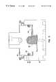
- FIG. 1Bis a side-elevational view of the pressure swing adsorption system of FIG. 1A;
- FIG. 1Cis a top plan view of the pressure swing adsorption system of FIG. 1A;
- FIG. 1Dis a cross-sectional view of the pressure swing adsorption system of FIG. 1A taken along line 1 D— 1 D of FIG. 1B;
- FIG. 1Eis a cross-sectional view of the pressure swing adsorption system of FIG. 1A taken along line 1 E— 1 E of FIG. 1C;
- FIG. 2is a partial, cross-sectional view of a top portion of the pressure swing adsorption system illustrated in FIG. 1A-1D;
- FIG. 3Ais a top perspective view of a rotary valve shoe constructed in accordance with a preferred embodiment of the invention.
- FIG. 3Bis a top plan view of the rotary valve shoe illustrated in FIG. 3A;
- FIG. 3Cis a cross-sectional view of the rotary valve shoe taken along line 3 C— 3 C of FIG. 3B;
- FIG. 3Dis a bottom plan view of the rotary valve shoe illustrated in FIG. 3A;
- FIG. 4Ais a top plan view of a valve port plate constructed in accordance with a preferred embodiment of the invention.
- FIG. 4Bis a cross-sectional view taken along lines 4 B— 4 B of FIG. 4A;
- FIG. 5is a cross-sectional view of an embodiment of the rotary valve shoe and a first drive shaft
- FIG. 6Ais a bottom plan view of an alternative embodiment of a rotary valve shoe
- FIG. 6Bis cross-sectional view of the rotary valve shoe illustrated in FIG. 6A taken along line 6 B— 6 B;
- FIG. 7Ais a top perspective view of a rotary valve shoe constructed in accordance with a further embodiment of the invention.
- FIG. 7Bis a top plan view of the rotary valve shoe illustrated in FIG. 7A;
- FIG. 7Cis a bottom plan view of the rotary valve shoe illustrated in FIG. 7A;
- FIG. 7Dis a side-elevational view of the rotary valve shoe illustrated in FIG. 7A;
- FIG. 7Eis a cross-sectional view of the rotary valve shoe taken along line 7 E— 7 E of FIG. 7A;
- FIG. 8is a partial, cross-sectional view of a top portion of a pressure swing adsorption system constructed in accordance with an alternative embodiment of the invention.
- FIG. 9is a perspective view of the valve port plate, top manifold member and bottom manifold member constructed in accordance with an embodiment of the invention.
- PSApressure swing adsorption
- fluidsincludes both gases and liquids. Although the present invention will be described in conjunction with the separation of nitrogen from air, it will be readily understood by those skilled in the art that the present invention applies to the fractionation of other fluids such as, but not by way of limitation, the separation of oxygen from air.
- the adsorption system 20includes multiple adsorption vessels 24 , each containing a bed of adsorbent material which is selective for a particular molecular species of fluid or contaminant, and the rotary valve assembly 22 .
- twelve adsorption vessels 24are included.
- the adsorption vessels 24preferably used in the system 20 include straight elongated vessels, as shown.
- the vessels 24may have a construction such as, but not by way of limitation, U-shaped or concentric.
- Each adsorption vessel 24includes a product end 28 and a feed end 30 .
- the feed ends 30communicate with respective feed lines or tubes 32 through passages in a header 34 .
- Springs 36are disposed near the bottoms of the adsorption vessels 24 to hold the packed beds of adsorbent material firmly in place.
- the product ends 28communicate with passages in a manifold 38 for communication with the rotary valve assembly 22 .
- the manifold 38is constructed of a top member 201 and a bottom member 202 .
- the manifold 38serves to connect the rotary valve assembly 22 with the adsorption vessels 24 at both the feed ends 30 (via the feed tube 32 ) and the product ends 28 .
- the two-piece constructionallows for the creation of passages that connect apertures in either the top member 201 or bottom member 202 .
- the preferred embodiment of the manifold 38has provision for flow control elements to be inserted in these internal passages to control the rate of flow of various fluid streams within the system 20 .
- the preferred embodimentincludes both feed orifices 210 and product orifices 211 that control the flow of gas streams into and out of the adsorption vessels 24 .
- one or more external passagesmay be added.
- thisis done with a feed U-tube 43 that connects a feed fitting or air feed inlet 41 at a convenient location on the manifold 38 to the appropriate position on the manifold 38 near the valve assembly 22 and a product U-tube 42 that connects a product fitting or product outlet 40 at a convenient location on the manifold 38 to the appropriate position on the manifold 38 near the valve assembly 22 .
- An annular groove 220(FIG. 9) in the top member 201 of the manifold 38 is used to introduce feed gas in the preferred embodiment.
- a single passage communicating to the annular groove 220is then able to supply a fluid stream to a multiplicity of apertures 112 in a port plate 46 of the rotary valve assembly 22 .
- the two members 201 , 202 making up the manifold 38are fastened together with a multiplicity of stay bolts to resist the separation force created by the fluid pressure present in the internal passages.
- a sealantis used to seal the various fluid passages so that there is no leakage from one passage to another or from a passage to an external surface.
- a number of methods exist to provide this sealing functionsuch as using a gasket, O-rings, adhesive material or the like.
- the sieve beds (not shown) of the adsorption vessels 24are a packed particulate adsorbent which preferentially adsorbs oxygen relative to nitrogen in the feed air so that nitrogen is produced as the non-adsorbed product gas.
- An adsorbentsuch as a carbon molecular sieve will provide this effect when the adsorption process is carried out on a kinetic basis.
- the resulting product nitrogen gasflows towards the products ends 28 of the adsorption vessels 24 , out product orifices 211 in the bottom member 202 , through product channels 230 , through product apertures 224 in the upper member 201 , and to the rotary valve assembly 22 , where it is distributed back through the manifold 38 via product aperture 226 of the upper member 201 and product aperture 234 of the lower member 202 to the product U-tube 42 .
- the product U-tube 42transfers the nitrogen product gas out to the nitrogen product outlet 40 .
- some of the product gas in the rotary valve assembly 22may be used to purge or regenerate beds in the adsorption vessels 24 .
- the rotary valve assembly 22includes a first valve member such as a rotary valve shoe or disk 44 and a second valve member such as a valve port plate or disk 46 .
- Both the rotary valve shoe 44 and valve port plate 46are preferably circular in construction. However, it will be readily understood by those skilled in the art that they may be shaped otherwise, for example, polygonal.
- the rotary valve shoe 44 and valve port plate 46are preferably made from a durable material such as ceramic, which can be ground to a highly polished flat finish to enable the faces of the valve shoe 44 and port plate 46 to form a fluid-tight seal when pressed together.
- the rotary valve shoe 44has a flat engagement surface 48 (FIG. 3D) and a cylindrical exterior surface 50 .
- the valve shoe 44has several symmetrical arcuate passages or channels cut into the engagement surface 48 , all of which have as its center the geometric center of the circular engagement surface 48 .
- the passages or channelsinclude opposite feed channels 52 , a first pair of equalization passages 54 , a second pair of equalization passages 56 , and opposite exhaust ports 58 (which open at the side wall 50 ).
- the passages or channelsare generally described below as means for transferring fluid from one part of the engagement surface 48 to another, the passages or channels may also be configured to transfer fluid from the engagement surface 48 , out of the rotary valve shoe 44 .
- the passages or channels related to the feed fluid or the feed end 30 of the adsorption vessels 24are part of a feed fluid section 59 .
- the engagement surface 48includes annular vent groove 60 and opposite passages 62 that extend from the vent groove 60 to the side wall 63 of the exhaust ports 58 .
- arcuate purge channels 64Near the center of the rotary valve shoe 44 are arcuate purge channels 64 , purge passages 66 in which flow control elements such as small orifices 68 are inserted, cross-port equalization channels 70 , and product channels 72 A and 72 B which respectively extend radially from a central product passage 74 to symmetrical opposite arcuate product channels or pockets 76 , 78 .
- Other flow control elementsmay be used besides small orifices 68 such as, but not by way of limitation, sintered metal elements or capillary tubes.
- the above-described passages or channels located at radial positions inside the groove 60 that relate to the product fluid or product ends 28 of the adsorption vessels 24are part of a product fluid section 79 .
- purge passages 66 and flow control elements 68are described, it will be readily understood by those skilled in the art that one or more purge passages 66 and flow control elements 68 may be incorporated into the rotary valve shoe 44 . If more than one flow control element 68 is used, it is desirable to match the flow characteristics of the flow control elements.
- FIGS. 6A and 6Ba rotary valve shoe 144 constructed in accordance with an alternative embodiment of the invention, which does not allow for product gas purge flow, is shown. Elements similar to those described above with respect to FIGS. 3A-3D are identified with numbers that include the same last two digits, but with a “1” prefix, i.e., 58 becomes 158 , 63 becomes 163 , etc. Because the embodiment of the rotary valve shoe 144 does not allow for product gas to be used as purge flow, the following elements described above with respect to FIGS. 3A-3D are not needed: pockets 64 , passages 66 , and flow control elements 68 .
- This embodiment of the rotary valve shoe 144is in fact the more common way to operate the nitrogen from air separation cycle when the adsorption vessels 24 are packed with a Carbon Molecular Sieve (CMS).
- CMSCarbon Molecular Sieve
- the rotary valve shoe 144includes opposite arcuate vent grooves 160 and multiple passages 162 that extend from the vent grooves 160 to the side wall 163 of the exhaust ports 158 .
- an upper part of the rotary valve shoe 44includes an upper annular surface 80 that surrounds a first annular recess 82 and a second surface 84 that surrounds an eccentric recess 86 .
- An eccentric floor 87defines a bottom part of the eccentric recess 86 .
- Equalization routing for the feed ends 30 of the adsorption vessels 24is done in a plane out of a plane generally defined by the engagement surface 48 of the rotary valve shoe 44 because of the limited amount of room available for this purpose on the engagement surface 48 .
- a first equalization tube 88 and a second equalization tube 90are bonded into passages 54 and 56 in the upper surface 80 of the rotary valve shoe 44 for interconnecting the first pair of equalization passages 54 and the second pair of equalization passages 56 , respectively.
- the first equalization tube 88 and equalization passages 54form a first passage adapted to communicate with the feed ends 30 of two adsorption vessels 24 for equalization purposes.
- the second equalization tube 90 and equalization passages 56form a second passage for this purpose.
- a rotary valve assembly 244constructed in accordance with an alternative embodiment of the invention, which interconnects each set of equalization passages 54 , 56 of the rotary valve shoe 44 in a different way, will now be described.
- the equalization passages 54 , 56extend from the engagement surface 48 to the sidewall 50 of the rotary valve shoe 44 .
- Each equalization passage 54 , 56is routed around the outer circumference or sidewall 50 of the rotary valve shoe 44 , underneath a ring 91 that is shrunk or bonded onto the sidewall 50 of the rotary valve shoe 44 , to interconnect each respective set of equalization passages 54 , 56 . It will be readily apparent to those skilled in the art that other ways exist to interconnect each set of equalization passages 54 , 56 of the rotary valve shoe 44 .
- the purge passages 66extend from the second surface 84 to the arcuate passages 64 of the rotary valve shoe 44 .
- the central product passage 74extends from the floor 87 of the eccentric recess 86 to the product channels 72 A, 72 B.
- the first and second annular recesses 82 , 86are configured to receive a first drive shaft 92 as shown in FIGS. 1, 2 and 5 .
- a drive motor 94has a second drive shaft 95 which extends through a top wall of a valve assembly cover 97 and extends into a recess 99 in a top part of the first drive shaft 92 .
- the motor 94is connected to a source of electric power and its shaft 95 drives the shaft 92 .
- the motor shaft 95rotates, it causes the rotary valve shoe 44 to rotate, to cycle the adsorption vessels 24 through the various steps of the adsorption process.
- the motor 94can impart continuous or stepwise rotation to the rotary valve shoe 44 around its center of rotation.
- the rotation of the valve 22preferably includes the first valve member 44 rotating and the second valve member 46 remaining stationary, in an alternative embodiment of the invention, the opposite may be true or both valve members 44 , 46 may rotate in the same or opposite directions.
- the valve members 44 , 46rotate at different speeds in the event they rotate in the same direction.
- a cavity 96 in the first drive shaft 92receives a spring 98 for applying a preload force against the rotary valve shoe 44 .
- the spring 98ensures that the rotary valve shoe 44 is in contact with the valve port plate 46 even at start-up, before a balance pressure (discussed below) is established.
- An O-ring 100is located in a groove 102 of the drive shaft 92 .
- valve port plate 46has a flat engagement surface 104 and a smooth cylindrical side wall 106 with opposite notches 108 therein.
- the valve port plate 46also includes multiple sets of symmetric concentrically disposed ports or openings.
- the openingspreferably extend completely through the valve port plate 46 in a direction generally perpendicular to the engagement surface 104 .
- the openingsmay have alternative configurations such as, but not by way of limitation, round-shaped, square-shaped, sector-shaped and elongated holes.
- the openingsmay also extend through the port plate 46 at a variety of angles. Preferably, all of the openings of each set have the same configuration.
- a first set of twelve obround openings 110are concentrically disposed at a first radius from the geometric center of the valve port plate 46 and interconnected with the feed ends 30 of the twelve adsorption vessels 24 .
- sets of twelve openingsare described herein, it will be readily apparent to those skilled in the art that other numbers of openings may be used. Further, the number of openings in each set need not match the number of absorption vessels 24 , the number could be more or less.
- a second set of twelve round feed openings 112 concentrically disposed at a second radius from the geometric center of the valve port plate 46are interconnected with the feed air inlet for delivering feed fluid to the valve assembly 22 .
- the feed openings 112have a first bore 118 and a smaller diameter second bore 120 .
- a third set of twelve round openings 114 concentrically disposed at a third radius from the geometric center of the valve port plate 46are interconnected with the product ends 28 of the twelve adsorption vessels 24 .
- a round central product opening 116 disposed at the geometric center of the valve port plate 46 and the center of rotation of the valve assembly 22is interconnected with the product U-tube 42 and outlet 40 for withdrawing product fluid.
- the openings 110 , 112are located in a feed fluid section 115 of the valve port plate 46 .
- the feed fluid section 115is the radial region of the valve port plate 46 outside of the vent groove 62 when the rotary valve shoe 44 is engaged in position with the valve port plate 46 .
- the openings 114 and central product opening 116are located in a product fluid section 117 of the valve port plate 46 .
- the product fluid section 117is the radial region of the valve port plate 46 inside of the vent groove 60 when the rotary valve shoe 44 is engaged in position with the valve port plate 46 .
- the flat engagement surface 48 of the rotary valve shoe 44engages the flat engagement surface 104 of the valve port plate 46 so that the surfaces 48 , 104 have the same geometric center. This center serves as the center of rotation of the rotary valve shoe 44 .
- the notches 108 in the port plate 46receive stop members 208 (FIG. 9) of the manifold 38 to prevent the port plate 46 from rotating or moving during rotation of the valve shoe 44 .
- conventional equipmentmay be used to supply feed fluid, monitor and automatically regulate the flow of product fluid from the system so that it can be fully automated to run continuously in an efficient manner.
- the pressure swing adsorption system and particularly the rotary valve assembly 22will now be described in use as it applies to the separation of nitrogen from air with the adsorption vessels 24 being packed with a particulate adsorbent, e.g., Carbon Molecular Sieve (CMS), which, based on a kinetic effect, preferentially adsorbs oxygen relative to nitrogen so that nitrogen is produced as the nonadsorbed product gas.
- a particulate adsorbente.g., Carbon Molecular Sieve (CMS)
- CMSCarbon Molecular Sieve
- the rotary valve shoe 44rotates in the valve assembly 22 .
- the rotary valve shoe 44preferably rotates with respect to the valve port plate 46 during use so that each cycle described below is sequentially and continuously established for each vessel 24 , to help the reader gain a better understanding of the invention the following description describes the relationship between what occurs in the valve assembly 22 and the adsorption vessels 24 while the rotary valve shoe 44 is in a single position because at any given position all of the adsorption vessels are at some point in the PSA cycle.
- the adsorption vessels 24undergo two complete PSA cycles. For each cycle, the steps include: 1) adsorption, 2) equalization down, 3) regeneration, and 4) equalization up. As the rotary valve shoe 44 rotates over the valve port plate 46 , each step described below is sequentially and continuously established for each vessel 24 .
- the rotary valve assemblymay be designed so that different number of cycles may be completed with each revolution of the rotary valve shoe 44 .
- the duration of the adsorption stages and purge stagesis constructed to be the same, it will be readily apparent to those skilled in the art that the timing of these stages (as well as the equalization stage) may be varied by changing the configuration and/or location of the openings and/or channels in the rotary valve assembly 22 .
- Compressed airis supplied to the system 20 at the air feed inlet 41 .
- the airmay be pre-treated to remove particulates and liquid water.
- Feed airflows through the feed air U-tube 43 and into the manifold 38 , where it is distributed via the feed air groove 220 to the valve assembly 22 .
- the valve assembly 22distributes the feed air to the multiple adsorption vessels 24 .
- the nonadsorbed product gasflows out of the product ends 28 of the respective vessels 24 , through product orifices 211 , product channels 230 and product apertures 224 in the manifold 38 and through openings 114 in the valve port plate 46 .
- the number of openings 114 through which product gas flows in the valve port plate 46typically corresponds with the number of aforementioned openings 110 through which the initial air flowed through the valve port plate 46 .
- the product gasflows into the arcuate channels 76 , 78 of the rotary valve shoe 44 and is channeled towards the center of the rotary valve shoe 44 through the product channels 72 A, 72 B.
- the pressure of the product gas in the space 96produces a pressure-balancing effect on the rotary valve shoe 44 .
- various pressure forces in the systeme.g., compressed feed air pressure, nitrogen product gas pressure, act to separate the shoe 44 from the port plate 46 at the engagement surface 48 .
- the pressure of the product gas in the space 96imparts a force on the rotary valve shoe 44 equal to or slightly greater than the pressure forces acting on the engagement surface 48 of the rotary valve shoe 44 , causing the engagement surface 48 of the rotary valve shoe 44 to be pressed firmly against the engagement surface 104 of the valve port plate 46 so as to inhibit leakage at this interface.
- Balanceis maintained over a broad range of operating pressures because pressure forces are all related and proportional to the inlet pressure.
- the O-ring 100is pressure actuated for ensuring a good seal between the rotary valve shoe 44 and the first shaft 92 .
- the aforementioned compression spring 98also biases the rotary valve shoe 44 against the valve port plate 46 .
- the spring 98is the only balancing force provided upon initial start-up of the PSA system, i.e., there is no balancing pressure in the space 96 .
- the balancing medium, i.e., product gas, in the space 96is also a convenient, controllable source of purge gas for the separation cycle.
- Product gas in the space 96flows out of the space 96 through the purge passages 66 .
- the flow out of the space 96i.e., the purge flow, is controlled by the small orifices 68 in the purge passages 66 .
- Product gasflows through the purge passages 66 and into the opposite purge channels 64 . In turn, product gas flows from the purge channels 64 through respective openings 114 in the valve port plate 46 .
- Product gasthen flows through appropriate through product apertures 224 , product channels 230 and product orifices 211 in the manifold 38 and into the product ends 28 of the respective adsorption vessels 24 .
- Product gasflows through the adsorbent material in the vessels 24 , regenerating the adsorbent beds of the vessels 24 and sweeping out oxygen adsorbed therein.
- purgingmay not take place. Consequently, the purge channels 64 and purge passages 66 , 68 may not exist.
- Resulting exhaust gasflows out of the feed ends 30 of the vessels 24 and into lines 32 .
- the exhaust gasflows out of the lines 32 , through feed orifices 210 , feed channels 232 and feed apertures 222 of the manifold 38 , through outer feed and exhaust openings 110 of the valve port plate 46 , and out of opposite exhaust ports 58 .
- the exhaust gas exiting the rotary valve shoe 44enters a chamber 118 between the rotary valve shoe 44 and the valve assembly cover 97 .
- the exhaust gasexits the system 20 through an exhaust outlet and an optional silencer (not shown) that is in communication with the chamber 118 .
- the exhaust gasmay be vented to the atmosphere or withdrawn for further use.
- a vacuummay be interconnected to the exhaust fitting to improve the withdrawal of the exhaust gas and assist in regeneration. Vacuum desorption may also be used if there is no purge option.
- the cover 97may be sealed at its interface with the manifold 38 and the shaft 92 of the rotary valve assembly 22 may be sealed at its penetration through the cover 97 with an O-ring or similar device to facilitate applying a vacuum or collecting waste gas for further use. Separation of nitrogen from air may be accomplished without a purge or regeneration stage. However, purging or regenerating the adsorbent beds is done to improve the purity of the product gas where a high purity product level is important.
- Equalization of the adsorption vessels 24will now be discussed. It is well known to equalize the pressure between adsorption vessels transitioning between the adsorbing and desorbing cycles to enhance product concentration and high product flow rates. This is done by equalizing the pressure between adsorption vessels that have just completed the adsorption step and adsorption vessels that have just completed the regeneration step.
- Cross-port equalization channels 70are used to equalize the pressure between the product ends of two adsorption vessels 24 where adsorption has just occurred with the product ends of two respective adsorption vessels 24 where regeneration has just occurred. This is accomplished upon rotation of the rotary valve shoe 44 where one end of a cross-port equalization channel 70 communicates with an opening 114 corresponding to a vessel 24 that just completed the adsorption phase and the other end of the same cross-port equalization channel 70 communicates with a corresponding opening 114 corresponding to a vessel 24 that just completed the regeneration phase.
- Each cross-port equalization channel 70serves as a bridge to communicate and, hence, equalize the pressures in the product ends 28 of the vessels 24 .
- first equalization passages 54 and equalization tubes 90 and second equalization passages 56 and equalization tubes 88serve to communicate and equalize the feed ends 30 of respective adsorption vessels 24 that have just completed the adsorption and regeneration steps.
- the first equalization passages 54 and second equalization passages 56communicate with the feed ends 30 of the vessels 24 through the openings 110 of the valve port plate 46 .
- Equalizationboth ends, i.e., feed-feed, product-product
- the vent groove 60prevents leakage from one section from reaching the other.
- leakage from the feed fluid section into the product fluid sectioni.e. leakage from the outer annular section into the inner annular section.
- Leakage from the feed section into the product sectionoccurs because feed gas, i.e., air, is at higher pressure than the product gas, i.e., nitrogen, and, hence, has a driving force of differential pressure in combination with the driving force caused by a large concentration gradient. These driving forces may lead to contamination of the high purity nitrogen product gas with oxygen from the feed gas.
- valve face interfacei.e., the engagement surfaces 48 , 104 of the rotary valve shoe 44 and valve port plate 46
- the leakagecannot be eliminated altogether since the valve assembly 22 depends on a thin fluid film being established between engagement surfaces 48 , 104 of the rotary valve shoe 44 and valve port plate 46 .
- desired product purityis in the range of tenths of percentage points oxygen to PPM (parts per million) levels of oxygen, it is not practical to use many of the rotary valve constructions proposed in the prior art.
- the annular vent groove 60is ported to the relatively low pressure of the valve assembly chamber 118 , where the exhaust gas normally flows, via the opposite passages 62 . Because the valve assembly chamber is in communication with the atmosphere via the exhaust outlet, the pressure within the chamber 118 is at approximately atmospheric pressure. Leaking gases that would normally flow from the feed section to the product section at the valve interface stop at the annular vent groove 60 and are withdrawn through the passages 62 to the chamber 118 , where they are then expelled to the atmosphere. Thus, leakage of feed gas into product gas is prevented.
- the vent groove 60may communicate with a vacuum, e.g., via chamber 118 , to further reduce the pressure in the groove 60 and improve the ability of the groove 60 to prevent contamination.
- the groove 60may be vented by passages 250 , 252 , 254 extending through the port plate 46 , upper manifold member 201 and lower manifold member 202 , respectively, to the external atmosphere (or a vacuum connection).
- passages 62Although two passages 62 are shown, it will be readily apparent to those skilled in the art that other numbers of passages, e.g., 1, 3, 4, etc., may be used.
- multiple passages 162may be used to increase the flow area for leaking fluid to limit pressure in the groove 160 to near atmospheric pressure (or pressure maintained in chamber 118 , e.g., with a vacuum). This limits the pressure drop through the passages and keeps the pressure in the vent groove 160 as low as possible.
- annular vent groove 60has been described as being located on the engagement surface 48 of the rotary valve shoe 44 , it may also be located on the engagement surface 104 of the valve port plate 46 . In this instance, the opposite passages 62 , i.e., vent ports, would preferably be made to pass through the port plate 46 .
- both the rotary valve shoe 44 and valve port plate 46may include opposing annular vent grooves on their respective engagement surfaces and venting could be done through either or both the rotary valve shoe 44 or the valve port plate 46 .
- N ⁇ 1 annular vent groovesmay exist in the rotary valve assembly, one between each pair of fluid sections where leakage between fluid sections is a concern.
- the vent groove 60may comprise one or more vent grooves, not necessarily annular, located between different fluid sections and vented to a lower pressure than the pressure of the fluids in the adjacent sections.
- the vent groove 60may comprise one or more vent grooves, not necessarily annular, located between different fluid sections and vented to a lower pressure than the pressure of the fluids in the adjacent sections.
- two arcuate vent grooves 160may be located between the product fluid section 179 and the feed fluid section 159 .
Landscapes
- Chemical & Material Sciences (AREA)
- Engineering & Computer Science (AREA)
- Analytical Chemistry (AREA)
- General Chemical & Material Sciences (AREA)
- Oil, Petroleum & Natural Gas (AREA)
- Chemical Kinetics & Catalysis (AREA)
- General Engineering & Computer Science (AREA)
- Mechanical Engineering (AREA)
- Separation Of Gases By Adsorption (AREA)
Abstract
Description
Claims (24)
Priority Applications (3)
| Application Number | Priority Date | Filing Date | Title |
|---|---|---|---|
| US09/371,464US6311719B1 (en) | 1999-08-10 | 1999-08-10 | Rotary valve assembly for pressure swing adsorption system |
| US09/925,146US6457485B2 (en) | 1999-08-10 | 2001-08-08 | Rotary valve assembly for pressure swing absorption system |
| US10/143,373US6712087B2 (en) | 1999-08-10 | 2002-05-10 | Rotary valve assembly for pressure swing adsorption system |
Applications Claiming Priority (1)
| Application Number | Priority Date | Filing Date | Title |
|---|---|---|---|
| US09/371,464US6311719B1 (en) | 1999-08-10 | 1999-08-10 | Rotary valve assembly for pressure swing adsorption system |
Related Child Applications (1)
| Application Number | Title | Priority Date | Filing Date |
|---|---|---|---|
| US09/925,146DivisionUS6457485B2 (en) | 1999-08-10 | 2001-08-08 | Rotary valve assembly for pressure swing absorption system |
Publications (1)
| Publication Number | Publication Date |
|---|---|
| US6311719B1true US6311719B1 (en) | 2001-11-06 |
Family
ID=23464096
Family Applications (3)
| Application Number | Title | Priority Date | Filing Date |
|---|---|---|---|
| US09/371,464Expired - LifetimeUS6311719B1 (en) | 1999-08-10 | 1999-08-10 | Rotary valve assembly for pressure swing adsorption system |
| US09/925,146Expired - LifetimeUS6457485B2 (en) | 1999-08-10 | 2001-08-08 | Rotary valve assembly for pressure swing absorption system |
| US10/143,373Expired - LifetimeUS6712087B2 (en) | 1999-08-10 | 2002-05-10 | Rotary valve assembly for pressure swing adsorption system |
Family Applications After (2)
| Application Number | Title | Priority Date | Filing Date |
|---|---|---|---|
| US09/925,146Expired - LifetimeUS6457485B2 (en) | 1999-08-10 | 2001-08-08 | Rotary valve assembly for pressure swing absorption system |
| US10/143,373Expired - LifetimeUS6712087B2 (en) | 1999-08-10 | 2002-05-10 | Rotary valve assembly for pressure swing adsorption system |
Country Status (1)
| Country | Link |
|---|---|
| US (3) | US6311719B1 (en) |
Cited By (96)
| Publication number | Priority date | Publication date | Assignee | Title |
|---|---|---|---|---|
| US20030005928A1 (en)* | 2000-08-03 | 2003-01-09 | Sequal Technologies, Inc. | Portable oxygen concentration system and method of using the same |
| US6514319B2 (en)* | 1999-12-09 | 2003-02-04 | Questair Technologies Inc. | Life support oxygen concentrator |
| US6533846B1 (en)* | 1999-06-10 | 2003-03-18 | Questair Technologies, Inc. | Modular pressure swing adsorption apparatus with clearance-type valve seals |
| WO2003074113A1 (en) | 2002-03-05 | 2003-09-12 | Teijin Limited | Oxygen enricher |
| US6729350B2 (en)* | 2001-05-25 | 2004-05-04 | Upchurch Scientific, Inc. | Valve for use with capillary tubing |
| US20040094216A1 (en)* | 2002-11-15 | 2004-05-20 | Wagner Glenn Paul | Rotary sequencing valve with flexible port plate |
| US20040197616A1 (en)* | 2003-04-01 | 2004-10-07 | Edlund David J. | Oxidant-enriched fuel cell system |
| WO2005025722A1 (en)* | 2003-09-09 | 2005-03-24 | Teijin Pharma Limited | Oxygen concentrating apparatus and rotary valve |
| US20050098033A1 (en)* | 2003-11-12 | 2005-05-12 | Kiran Mallavarapu | Control of a hydrogen purifying pressure swing adsorption unit in fuel processor module for hydrogen generation |
| US20050132881A1 (en)* | 2003-12-23 | 2005-06-23 | Baksh Mohamed S.A. | Indexing rotary dual valve for pressure swing adsorption systems |
| US20050145111A1 (en)* | 1997-12-01 | 2005-07-07 | Questair Technologies, Inc. | Modular pressure swing adsorption apparatus |
| US20050183572A1 (en)* | 1999-12-09 | 2005-08-25 | Questair Technologies Inc. | Life support oxygen concentrator |
| US20060076270A1 (en)* | 2004-10-07 | 2006-04-13 | Poshusta Joseph C | Desulfurization method, apparatus, and materials |
| US20060130650A1 (en)* | 2004-12-20 | 2006-06-22 | Givens James A | Temperature-based breakthrough detection and pressure swing adsorption systems and fuel processing systems including the same |
| US7066985B2 (en) | 2003-10-07 | 2006-06-27 | Inogen, Inc. | Portable gas fractionalization system |
| US20060174880A1 (en)* | 2005-02-09 | 2006-08-10 | Vbox, Incorporated | Ambulatory oxygen concentrator containing a three phase vacuum separation system |
| US20060174877A1 (en)* | 2005-02-09 | 2006-08-10 | Vbox, Incorporated | Portable oxygen concentrator with a docking station |
| US20060174882A1 (en)* | 2005-02-09 | 2006-08-10 | Vbox, Incorporated | Method of controlling the rate of oxygen produced by an oxygen concentrator |
| US20060174881A1 (en)* | 2005-02-09 | 2006-08-10 | Vbox, Incorporated | Method of providing ambulatory oxygen |
| US20060174872A1 (en)* | 2005-02-09 | 2006-08-10 | Vbox, Incorporated | Method and apparatus for controlling the purity of oxygen produced by an oxygen concentrator |
| US20060174875A1 (en)* | 2005-02-09 | 2006-08-10 | Vbox, Incorporated | Ambulatory oxygen concentrator containing a power pack |
| US20060174873A1 (en)* | 2005-02-09 | 2006-08-10 | Vbox, Incorporated | Product pump for an oxygen concentrator |
| US20060174871A1 (en)* | 2005-02-09 | 2006-08-10 | Vbox, Incorporated | Ambulatory oxygen concentrator with high efficiency adsorbent |
| US20060174876A1 (en)* | 2005-02-09 | 2006-08-10 | Vbox, Incorporated | Personal oxygen concentrator |
| US20060174878A1 (en)* | 2005-02-09 | 2006-08-10 | Vbox, Incorporated | Low power ambulatory oxygen concentrator |
| US20060174874A1 (en)* | 2005-02-09 | 2006-08-10 | Vbox, Incorporated | Adsorbent cartridge for oxygen concentrator |
| US7135059B2 (en) | 2003-10-07 | 2006-11-14 | Inogen, Inc. | Portable gas fractionalization system |
| US20070028971A1 (en)* | 2005-08-05 | 2007-02-08 | Wagner Glenn P | Rotary valve with internal leak control system |
| US20070119456A1 (en)* | 2005-11-29 | 2007-05-31 | Scott Mark H | Hypoxic gas stream system and method of use |
| US20080000353A1 (en)* | 2006-06-30 | 2008-01-03 | Air Products And Chemicals, Inc. | Pressure Swing Adsorption System With Indexed Rotatable Multi-Port Valves |
| US20080148935A1 (en)* | 2004-12-20 | 2008-06-26 | Idatech, Llc | Temperature-based breakthrough detection and pressure swing adsorption systems and fuel processing systems including the same |
| US7399342B2 (en) | 2004-12-22 | 2008-07-15 | Idatech, Llc | Systems and methods for regulating heating assembly operation through pressure swing adsorption purge control |
| WO2008089564A1 (en)* | 2007-01-24 | 2008-07-31 | Xebec Adsorption Inc. | Gas separation device |
| US7438745B2 (en) | 2003-10-07 | 2008-10-21 | Inogen, Inc. | Portable gas fractionalization system |
| US20090095154A1 (en)* | 2007-10-12 | 2009-04-16 | Hamilton Sundstrand Corporation | Rotary cylinder dual diverter valve |
| US20090107332A1 (en)* | 2007-10-29 | 2009-04-30 | Air Products And Chemicals, Inc. | Rotary Valve |
| US20090193774A1 (en)* | 2007-10-09 | 2009-08-06 | Giovanni Zanni | Modular gas-separating adsorbers |
| US7686870B1 (en) | 2005-12-29 | 2010-03-30 | Inogen, Inc. | Expandable product rate portable gas fractionalization system |
| US7837765B2 (en) | 2007-12-12 | 2010-11-23 | Idatech, Llc | Systems and methods for supplying auxiliary fuel streams during intermittent byproduct discharge from pressure swing adsorption assemblies |
| WO2011026730A1 (en)* | 2009-09-01 | 2011-03-10 | Joachim Klein | Pressure swing adsorption system and pressure swing adsorption method |
| US7922789B1 (en) | 2003-10-07 | 2011-04-12 | Inogen, Inc. | Portable gas fractionalization system |
| US8070841B2 (en) | 2007-12-12 | 2011-12-06 | Idatech, Llc | Systems and methods for supplying auxiliary fuel streams during intermittent byproduct discharge from pressure swing adsorption assemblies |
| US8210205B2 (en) | 2006-03-09 | 2012-07-03 | Michaels Gregory A | Rotary valve assembly |
| US8394178B2 (en) | 2009-07-22 | 2013-03-12 | Vbox, Incorporated | Apparatus for separating oxygen from ambient air |
| US8574346B2 (en) | 2006-09-25 | 2013-11-05 | L'air Liquide Societe Anonyme Pour L'etude Et L'exploitation Des Procedes Georges Claude | PSA method using a composite adsorption bed comprising an adsorbent and PCM agglomerates |
| WO2012118759A3 (en)* | 2011-03-01 | 2014-04-17 | Exxonmobil Upstream Research Company | Apparatus and systems having a rotary valve assembly and swing adsorption processes related thereto |
| US8906138B2 (en) | 2007-11-12 | 2014-12-09 | Exxonmobil Upstream Research Company | Methods of generating and utilizing utility gas |
| US8921637B2 (en) | 2010-11-15 | 2014-12-30 | Exxonmobil Upstream Research Company | Kinetic fractionators, and cycling processes for fractionation of gas mixtures |
| US9017457B2 (en) | 2011-03-01 | 2015-04-28 | Exxonmobil Upstream Research Company | Apparatus and systems having a reciprocating valve head assembly and swing adsorption processes related thereto |
| US9034078B2 (en) | 2012-09-05 | 2015-05-19 | Exxonmobil Upstream Research Company | Apparatus and systems having an adsorbent contactor and swing adsorption processes related thereto |
| US9034079B2 (en) | 2011-03-01 | 2015-05-19 | Exxonmobil Upstream Research Company | Methods of removing contaminants from hydrocarbon stream by swing adsorption and related apparatus and systems |
| US9067168B2 (en) | 2010-05-28 | 2015-06-30 | Exxonmobil Upstream Research Company | Integrated adsorber head and valve design and swing adsorption methods related thereto |
| US9126138B2 (en) | 2008-04-30 | 2015-09-08 | Exxonmobil Upstream Research Company | Method and apparatus for removal of oil from utility gas stream |
| US9162175B2 (en) | 2011-03-01 | 2015-10-20 | Exxonmobil Upstream Research Company | Apparatus and systems having compact configuration multiple swing adsorption beds and methods related thereto |
| US9168485B2 (en) | 2011-03-01 | 2015-10-27 | Exxonmobil Upstream Research Company | Methods of removing contaminants from a hydrocarbon stream by swing adsorption and related apparatus and systems |
| US9303775B2 (en) | 2012-12-21 | 2016-04-05 | Waters Technologies Corporation | Rotary shear valve and associated methods |
| US9352269B2 (en) | 2011-03-01 | 2016-05-31 | Exxonmobil Upstream Research Company | Apparatus and systems having a rotary valve assembly and swing adsorption processes related thereto |
| US9358493B2 (en) | 2011-03-01 | 2016-06-07 | Exxonmobil Upstream Research Company | Apparatus and systems having an encased adsorbent contactor and swing adsorption processes related thereto |
| US9675925B2 (en) | 2014-07-25 | 2017-06-13 | Exxonmobil Upstream Research Company | Apparatus and system having a valve assembly and swing adsorption processes related thereto |
| US9713787B2 (en) | 2014-12-10 | 2017-07-25 | Exxonmobil Upstream Research Company | Adsorbent-incorporated polymer fibers in packed bed and fabric contactors, and methods and devices using same |
| US9744521B2 (en) | 2014-12-23 | 2017-08-29 | Exxonmobil Upstream Research Company | Structured adsorbent beds, methods of producing the same and uses thereof |
| US9751041B2 (en) | 2015-05-15 | 2017-09-05 | Exxonmobil Upstream Research Company | Apparatus and system for swing adsorption processes related thereto |
| CN107138022A (en)* | 2017-07-10 | 2017-09-08 | 成都赛普瑞兴科技有限公司 | A kind of gas decarbonization system and gas handling system |
| CN107158883A (en)* | 2017-07-10 | 2017-09-15 | 成都赛普瑞兴科技有限公司 | A kind of air dryer systems and gas handling system |
| CN107185355A (en)* | 2017-07-10 | 2017-09-22 | 成都赛普瑞兴科技有限公司 | A kind of O2Purification system and gas handling system |
| CN107213748A (en)* | 2017-07-10 | 2017-09-29 | 成都赛普瑞兴科技有限公司 | A kind of CO purification systems and rotary valve |
| CN107213750A (en)* | 2017-07-10 | 2017-09-29 | 成都赛普瑞兴科技有限公司 | A kind of H2Purification system and gas handling system |
| CN107213749A (en)* | 2017-07-10 | 2017-09-29 | 成都赛普瑞兴科技有限公司 | A kind of CO2Purification system and gas handling system |
| CN107224840A (en)* | 2017-07-10 | 2017-10-03 | 成都赛普瑞兴科技有限公司 | A kind of N2Purification system and gas handling system |
| US9861929B2 (en) | 2015-05-15 | 2018-01-09 | Exxonmobil Upstream Research Company | Apparatus and system for swing adsorption processes related thereto |
| CN108087575A (en)* | 2017-12-29 | 2018-05-29 | 江苏中研宜普科技有限公司 | The high-efficiency sealing device of ring type rotary valve |
| US10040022B2 (en) | 2015-10-27 | 2018-08-07 | Exxonmobil Upstream Research Company | Apparatus and system for swing adsorption processes related thereto |
| WO2018151905A1 (en) | 2017-02-15 | 2018-08-23 | Exxonmobil Research And Engineering Company | Fast cycle gas phase simulated moving bed apparatus and process |
| US10080991B2 (en) | 2015-09-02 | 2018-09-25 | Exxonmobil Upstream Research Company | Apparatus and system for swing adsorption processes related thereto |
| US10220346B2 (en) | 2015-10-27 | 2019-03-05 | Exxonmobil Upstream Research Company | Apparatus and system for swing adsorption processes related thereto |
| US10220345B2 (en) | 2015-09-02 | 2019-03-05 | Exxonmobil Upstream Research Company | Apparatus and system for swing adsorption processes related thereto |
| US10322365B2 (en) | 2015-10-27 | 2019-06-18 | Exxonmobil Upstream Reseach Company | Apparatus and system for swing adsorption processes related thereto |
| US10328382B2 (en) | 2016-09-29 | 2019-06-25 | Exxonmobil Upstream Research Company | Apparatus and system for testing swing adsorption processes |
| US10427091B2 (en) | 2016-05-31 | 2019-10-01 | Exxonmobil Upstream Research Company | Apparatus and system for swing adsorption processes |
| US10427088B2 (en) | 2016-03-18 | 2019-10-01 | Exxonmobil Upstream Research Company | Apparatus and system for swing adsorption processes related thereto |
| US10427089B2 (en) | 2016-05-31 | 2019-10-01 | Exxonmobil Upstream Research Company | Apparatus and system for swing adsorption processes |
| US10434458B2 (en) | 2016-08-31 | 2019-10-08 | Exxonmobil Upstream Research Company | Apparatus and system for swing adsorption processes related thereto |
| US10549230B2 (en) | 2016-12-21 | 2020-02-04 | Exxonmobil Upstream Research Company | Self-supporting structures having active materials |
| US10603626B2 (en) | 2016-09-01 | 2020-03-31 | Exxonmobil Upstream Research Company | Swing adsorption processes using zeolite structures |
| US10675615B2 (en) | 2014-11-11 | 2020-06-09 | Exxonmobil Upstream Research Company | High capacity structures and monoliths via paste imprinting |
| US10710053B2 (en) | 2016-12-21 | 2020-07-14 | Exxonmobil Upstream Research Company | Self-supporting structures having active materials |
| US10744449B2 (en) | 2015-11-16 | 2020-08-18 | Exxonmobil Upstream Research Company | Adsorbent materials and methods of adsorbing carbon dioxide |
| US10799663B1 (en) | 2018-12-05 | 2020-10-13 | Aires Medical LLC | Pulsed pressure swing adsorption system and method |
| US10882003B2 (en) | 2016-06-29 | 2021-01-05 | Koninklijke Philips N.V. | Rotary valve assembly for sieve beds for pressure swing adsorption control |
| CN113230823A (en)* | 2021-05-13 | 2021-08-10 | 成都联帮医疗科技股份有限公司 | Multi-channel airflow switching device for medical molecular sieve oxygen generation system |
| US11318410B2 (en) | 2018-12-21 | 2022-05-03 | Exxonmobil Upstream Research Company | Flow modulation systems, apparatus, and methods for cyclical swing adsorption |
| US11331620B2 (en) | 2018-01-24 | 2022-05-17 | Exxonmobil Upstream Research Company | Apparatus and system for swing adsorption processes |
| US11376545B2 (en) | 2019-04-30 | 2022-07-05 | Exxonmobil Upstream Research Company | Rapid cycle adsorbent bed |
| US11413567B2 (en) | 2018-02-28 | 2022-08-16 | Exxonmobil Upstream Research Company | Apparatus and system for swing adsorption processes |
| US11433346B2 (en) | 2019-10-16 | 2022-09-06 | Exxonmobil Upstream Research Company | Dehydration processes utilizing cationic zeolite RHO |
| US11655910B2 (en) | 2019-10-07 | 2023-05-23 | ExxonMobil Technology and Engineering Company | Adsorption processes and systems utilizing step lift control of hydraulically actuated poppet valves |
Families Citing this family (43)
| Publication number | Priority date | Publication date | Assignee | Title |
|---|---|---|---|---|
| US6921597B2 (en) | 1998-09-14 | 2005-07-26 | Questair Technologies Inc. | Electrical current generation system |
| AU2002214858A1 (en)* | 2000-10-27 | 2002-05-06 | Questair Technologies, Inc. | Systems and processes for providing hydrogen to fuel cells |
| US7097925B2 (en) | 2000-10-30 | 2006-08-29 | Questair Technologies Inc. | High temperature fuel cell power plant |
| CA2325072A1 (en)* | 2000-10-30 | 2002-04-30 | Questair Technologies Inc. | Gas separation for molten carbonate fuel cell |
| CA2476409A1 (en) | 2002-03-14 | 2003-09-18 | Questair Technologies Inc. | Hydrogen recycle for solid oxide fuel cell |
| CA2477262A1 (en)* | 2002-03-14 | 2003-09-18 | Questair Technologies Inc. | Gas separation by combined pressure swing and displacement purge |
| US7285350B2 (en) | 2002-09-27 | 2007-10-23 | Questair Technologies Inc. | Enhanced solid oxide fuel cell systems |
| US6936091B2 (en)* | 2003-09-17 | 2005-08-30 | Metso Automation Usa, Inc. | System and method for treating fluid using a multi-port valve assembly |
| US20050098034A1 (en)* | 2003-11-12 | 2005-05-12 | Gittleman Craig S. | Hydrogen purification process using pressure swing adsorption for fuel cell applications |
| WO2005082107A2 (en)* | 2004-02-26 | 2005-09-09 | Ameriflo, Inc. | Method and apparatus for regulating fluid flow or conserving fluid flow |
| US7617826B1 (en) | 2004-02-26 | 2009-11-17 | Ameriflo, Inc. | Conserver |
| US7443803B2 (en)* | 2004-03-23 | 2008-10-28 | Fujitsu Limited | Estimating and managing network traffic |
| US7189280B2 (en) | 2004-06-29 | 2007-03-13 | Questair Technologies Inc. | Adsorptive separation of gas streams |
| WO2006052937A2 (en) | 2004-11-05 | 2006-05-18 | Questair Technologies, Inc. | Separation of carbon dioxide from other gases |
| US7354464B2 (en)* | 2004-12-17 | 2008-04-08 | Texaco Inc. | Apparatus and method for producing hydrogen |
| US7402287B2 (en)* | 2004-12-17 | 2008-07-22 | Texaco Inc. | Apparatus and methods for producing hydrogen |
| US7892304B2 (en)* | 2004-12-17 | 2011-02-22 | Texaco Inc. | Apparatus and method for controlling compressor motor speed in a hydrogen generator |
| US7354463B2 (en)* | 2004-12-17 | 2008-04-08 | Texaco Inc. | Apparatus and methods for producing hydrogen |
| US7368005B2 (en) | 2005-04-05 | 2008-05-06 | Respironics Oxytec, Inc. | Portable oxygen concentrator |
| US7402193B2 (en) | 2005-04-05 | 2008-07-22 | Respironics Oxytec, Inc. | Portable oxygen concentrator |
| US7329304B2 (en)* | 2005-04-05 | 2008-02-12 | Respironics Oxytec, Inc. | Portable oxygen concentrator |
| KR20070119068A (en)* | 2005-04-15 | 2007-12-18 | 데이진 화-마 가부시키가이샤 | Oxygen concentrator |
| US8062610B2 (en)* | 2005-05-16 | 2011-11-22 | The United States of America as represented by Environmental Protection Agency | Apparatus and methods for use in concentration of gas and particle-laden gas flows |
| US20070289445A1 (en)* | 2006-06-15 | 2007-12-20 | Mei Hua | Compact and efficient pressure swing oxygen concentrator |
| WO2008051606A2 (en) | 2006-10-27 | 2008-05-02 | Questair Technologies Inc. | Compact pressure swing reformer |
| US7503274B2 (en)* | 2007-05-10 | 2009-03-17 | Ronald T. WEED, JR. | Floating lift for watercraft |
| US7921876B2 (en)* | 2007-11-28 | 2011-04-12 | Halliburton Energy Services, Inc. | Rotary control valve and associated actuator control system |
| US20090205493A1 (en)* | 2008-02-20 | 2009-08-20 | Thompson Loren M | Method of removing water from an inlet region of an oxygen generating system |
| US20090205494A1 (en)* | 2008-02-20 | 2009-08-20 | Mcclain Michael S | Single manifold assembly for oxygen-generating systems |
| US7722698B2 (en)* | 2008-02-21 | 2010-05-25 | Delphi Technologies, Inc. | Method of determining the purity of oxygen present in an oxygen-enriched gas produced from an oxygen delivery system |
| US20090211443A1 (en)* | 2008-02-21 | 2009-08-27 | Youngblood James H | Self-serviceable filter for an oxygen generating device |
| US20090214393A1 (en)* | 2008-02-22 | 2009-08-27 | Chekal Michael P | Method of generating an oxygen-enriched gas for a user |
| US8075676B2 (en) | 2008-02-22 | 2011-12-13 | Oxus America, Inc. | Damping apparatus for scroll compressors for oxygen-generating systems |
| US20090229460A1 (en)* | 2008-03-13 | 2009-09-17 | Mcclain Michael S | System for generating an oxygen-enriched gas |
| US20090320928A1 (en)* | 2008-06-30 | 2009-12-31 | Uop Llc | Multi-track rotary valve in combination with a pressure reducer and method for operating the combination |
| US8127834B2 (en)* | 2009-01-13 | 2012-03-06 | Halliburton Energy Services, Inc. | Modular electro-hydraulic controller for well tool |
| USD620555S1 (en)* | 2009-04-01 | 2010-07-27 | Pelletron Corporation | Housing for a rotary valve |
| CA2767777C (en)* | 2009-06-29 | 2017-02-14 | Jr Franklin D. Lomax | Method and manifold for carrying reduced moment due to dimensional change in pressure vessel; removable insert with valve seat; pressure assisted valve arrangement and method |
| US8695633B2 (en) | 2010-09-09 | 2014-04-15 | Uop Llc | Control of rotary valve operation for reducing wear |
| US8753430B2 (en) | 2011-05-10 | 2014-06-17 | Uop Llc | Affixing a seal sheet to a rotor of a rotary valve |
| DE102014211703A1 (en)* | 2013-06-24 | 2014-12-24 | MAHLE Behr GmbH & Co. KG | Rotary valve for an adsorption heat pump |
| BE1023062A1 (en) | 2015-05-13 | 2016-11-16 | Atlas Copco Airpower Nv | Device for drying a compressed gas and compressor installation provided with such a device. |
| CN112223365B (en)* | 2020-09-27 | 2022-03-29 | 重庆三创印刷有限公司 | Cutting device of printing machine |
Citations (5)
| Publication number | Priority date | Publication date | Assignee | Title |
|---|---|---|---|---|
| US5268021A (en) | 1989-11-20 | 1993-12-07 | Dynotec Corporation | Fluid fractionator |
| USRE35099E (en) | 1989-11-20 | 1995-11-28 | Sequal Technologies, Inc. | Fluid fractionator |
| US5807423A (en) | 1996-09-27 | 1998-09-15 | The Boc Group, Inc. | Process and apparatus for gas separation |
| US5814131A (en) | 1996-09-27 | 1998-09-29 | The Boc Group, Inc. | Process and apparatus for gas separation |
| US5814130A (en) | 1996-09-27 | 1998-09-29 | The Boc Group, Inc. | Process and apparatus for gas separation |
Family Cites Families (10)
| Publication number | Priority date | Publication date | Assignee | Title |
|---|---|---|---|---|
| FR2236129A1 (en)* | 1973-07-04 | 1975-01-31 | Jentsce Hans | Multi-way cock for bottle filling appts. - has rotary spring loaded conical valve head on conical seat |
| US4161191A (en)* | 1975-11-06 | 1979-07-17 | Knorr-Bremse-Bowles-Fluidics GmbH | Adaptor for connection to a faucet |
| DE3013651A1 (en)* | 1980-04-09 | 1981-10-15 | Kludi-Armaturen Paul Scheffer, 5758 Fröndenberg | MIXED BATTERY |
| US5112367A (en)* | 1989-11-20 | 1992-05-12 | Hill Charles C | Fluid fractionator |
| US5114441A (en)* | 1990-11-02 | 1992-05-19 | Ryder International Corporation | Oxygen concentrator system and valve structure |
| DE4318203C1 (en)* | 1993-06-01 | 1994-09-15 | Ppv Verwaltungs Ag | Rotary slide valve and use thereof |
| US5827358A (en)* | 1996-11-08 | 1998-10-27 | Impact Mst, Incorporation | Rapid cycle pressure swing adsorption oxygen concentration method and apparatus |
| US5891217A (en)* | 1997-01-21 | 1999-04-06 | The Boc Group, Inc. | Process and apparatus for gas separation |
| US5820656A (en)* | 1997-01-21 | 1998-10-13 | The Boc Group, Inc. | Process and apparatus for gas separation |
| DE19743922C1 (en)* | 1997-10-04 | 1999-04-15 | Verschleis Schutz Technik Dr I | CVD surface coating process and CVD reactor system |
- 1999
- 1999-08-10USUS09/371,464patent/US6311719B1/ennot_activeExpired - Lifetime
- 2001
- 2001-08-08USUS09/925,146patent/US6457485B2/ennot_activeExpired - Lifetime
- 2002
- 2002-05-10USUS10/143,373patent/US6712087B2/ennot_activeExpired - Lifetime
Patent Citations (6)
| Publication number | Priority date | Publication date | Assignee | Title |
|---|---|---|---|---|
| US5268021A (en) | 1989-11-20 | 1993-12-07 | Dynotec Corporation | Fluid fractionator |
| US5366541A (en) | 1989-11-20 | 1994-11-22 | Dynotec Corporation | Fluid fractionator |
| USRE35099E (en) | 1989-11-20 | 1995-11-28 | Sequal Technologies, Inc. | Fluid fractionator |
| US5807423A (en) | 1996-09-27 | 1998-09-15 | The Boc Group, Inc. | Process and apparatus for gas separation |
| US5814131A (en) | 1996-09-27 | 1998-09-29 | The Boc Group, Inc. | Process and apparatus for gas separation |
| US5814130A (en) | 1996-09-27 | 1998-09-29 | The Boc Group, Inc. | Process and apparatus for gas separation |
Cited By (176)
| Publication number | Priority date | Publication date | Assignee | Title |
|---|---|---|---|---|
| US20050145111A1 (en)* | 1997-12-01 | 2005-07-07 | Questair Technologies, Inc. | Modular pressure swing adsorption apparatus |
| US7094275B2 (en)* | 1997-12-01 | 2006-08-22 | Questair Technologies, Inc. | Modular pressure swing adsorption apparatus |
| US6533846B1 (en)* | 1999-06-10 | 2003-03-18 | Questair Technologies, Inc. | Modular pressure swing adsorption apparatus with clearance-type valve seals |
| US6514319B2 (en)* | 1999-12-09 | 2003-02-04 | Questair Technologies Inc. | Life support oxygen concentrator |
| US20050183572A1 (en)* | 1999-12-09 | 2005-08-25 | Questair Technologies Inc. | Life support oxygen concentrator |
| US20030196550A1 (en)* | 1999-12-09 | 2003-10-23 | Questair Technologies Inc. | Life support oxygen concentrator |
| US7250073B2 (en) | 1999-12-09 | 2007-07-31 | Questair Technologies, Inc. | Life support oxygen concentrator |
| US20030005928A1 (en)* | 2000-08-03 | 2003-01-09 | Sequal Technologies, Inc. | Portable oxygen concentration system and method of using the same |
| US6691702B2 (en)* | 2000-08-03 | 2004-02-17 | Sequal Technologies, Inc. | Portable oxygen concentration system and method of using the same |
| US6729350B2 (en)* | 2001-05-25 | 2004-05-04 | Upchurch Scientific, Inc. | Valve for use with capillary tubing |
| US7179326B2 (en) | 2002-03-05 | 2007-02-20 | Teijin Limited | Oxygen concentration apparatus |
| US20050204923A1 (en)* | 2002-03-05 | 2005-09-22 | Hitoshi Nakamura | Oxygen enricher |
| WO2003074113A1 (en) | 2002-03-05 | 2003-09-12 | Teijin Limited | Oxygen enricher |
| US6889710B2 (en) | 2002-11-15 | 2005-05-10 | Air Products And Chemicals, Inc. | Rotary sequencing valve with flexible port plate |
| US20040094216A1 (en)* | 2002-11-15 | 2004-05-20 | Wagner Glenn Paul | Rotary sequencing valve with flexible port plate |
| US20040197616A1 (en)* | 2003-04-01 | 2004-10-07 | Edlund David J. | Oxidant-enriched fuel cell system |
| WO2005025722A1 (en)* | 2003-09-09 | 2005-03-24 | Teijin Pharma Limited | Oxygen concentrating apparatus and rotary valve |
| US20060283325A1 (en)* | 2003-09-09 | 2006-12-21 | Masato Sugano | Oxygen concentrating apparatus and rotary valve |
| US7753996B1 (en) | 2003-10-07 | 2010-07-13 | Inogen, Inc. | Portable gas fractionalization system |
| US7066985B2 (en) | 2003-10-07 | 2006-06-27 | Inogen, Inc. | Portable gas fractionalization system |
| US7922789B1 (en) | 2003-10-07 | 2011-04-12 | Inogen, Inc. | Portable gas fractionalization system |
| US7135059B2 (en) | 2003-10-07 | 2006-11-14 | Inogen, Inc. | Portable gas fractionalization system |
| US7438745B2 (en) | 2003-10-07 | 2008-10-21 | Inogen, Inc. | Portable gas fractionalization system |
| US7730887B2 (en) | 2003-10-07 | 2010-06-08 | Inogen, Inc. | Portable gas fractionalization system |
| US20050098033A1 (en)* | 2003-11-12 | 2005-05-12 | Kiran Mallavarapu | Control of a hydrogen purifying pressure swing adsorption unit in fuel processor module for hydrogen generation |
| US7011693B2 (en)* | 2003-11-12 | 2006-03-14 | General Motors Corporation | Control of a hydrogen purifying pressure swing adsorption unit in fuel processor module for hydrogen generation |
| US7276107B2 (en)* | 2003-12-23 | 2007-10-02 | Praxair Technology, Inc. | Indexing rotary dual valve for pressure swing adsorption systems |
| US20050132881A1 (en)* | 2003-12-23 | 2005-06-23 | Baksh Mohamed S.A. | Indexing rotary dual valve for pressure swing adsorption systems |
| US20080289496A1 (en)* | 2004-10-07 | 2008-11-27 | Poshusta Joseph C | Method for removing sulfur or other contaminant species from hydrocarbon fuels or other fuels |
| US20060076270A1 (en)* | 2004-10-07 | 2006-04-13 | Poshusta Joseph C | Desulfurization method, apparatus, and materials |
| US7837862B2 (en)* | 2004-10-07 | 2010-11-23 | Protonex Technology, LLC | Method for removing sulfur or other contaminant species from hydrocarbon fuels or other fuels |
| US7344686B2 (en) | 2004-10-07 | 2008-03-18 | Mesoscopic Devices, Inc. | Desulfurization apparatus with individually controllable heaters |
| US7833311B2 (en) | 2004-12-20 | 2010-11-16 | Idatech, Llc | Temperature-based breakthrough detection and pressure swing adsorption systems and fuel processing systems including the same |
| US7393382B2 (en) | 2004-12-20 | 2008-07-01 | Idatech Llc | Temperature-based breakthrough detection and pressure swing adsorption systems and fuel processing systems including the same |
| US20080148935A1 (en)* | 2004-12-20 | 2008-06-26 | Idatech, Llc | Temperature-based breakthrough detection and pressure swing adsorption systems and fuel processing systems including the same |
| US20060130650A1 (en)* | 2004-12-20 | 2006-06-22 | Givens James A | Temperature-based breakthrough detection and pressure swing adsorption systems and fuel processing systems including the same |
| US20080302011A1 (en)* | 2004-12-22 | 2008-12-11 | Idatech, Llc | Systems and methods for regulating heating assembly operation through pressure swing adsorption purge control |
| US7833326B2 (en) | 2004-12-22 | 2010-11-16 | Idatech, Llc | Systems and methods for regulating heating assembly operation through pressure swing adsorption purge control |
| US7399342B2 (en) | 2004-12-22 | 2008-07-15 | Idatech, Llc | Systems and methods for regulating heating assembly operation through pressure swing adsorption purge control |
| US8038771B2 (en) | 2004-12-22 | 2011-10-18 | Idatech, Llc | Systems and methods for regulating heating assembly operation through pressure swing adsorption purge control |
| US20060174881A1 (en)* | 2005-02-09 | 2006-08-10 | Vbox, Incorporated | Method of providing ambulatory oxygen |
| US20060174877A1 (en)* | 2005-02-09 | 2006-08-10 | Vbox, Incorporated | Portable oxygen concentrator with a docking station |
| US20070056584A1 (en)* | 2005-02-09 | 2007-03-15 | Vbox, Incorporated | Oxygen concentrator with a product pump |
| US20060174880A1 (en)* | 2005-02-09 | 2006-08-10 | Vbox, Incorporated | Ambulatory oxygen concentrator containing a three phase vacuum separation system |
| US20070056583A1 (en)* | 2005-02-09 | 2007-03-15 | Vbox, Incorporated | Product pump for an oxygen concentrator |
| US10357628B2 (en) | 2005-02-09 | 2019-07-23 | 3B Medical Manufacturing Llc | Removable cartridge for oxygen concentrator |
| US7171963B2 (en) | 2005-02-09 | 2007-02-06 | Vbox, Incorporated | Product pump for an oxygen concentrator |
| US7121276B2 (en) | 2005-02-09 | 2006-10-17 | Vbox, Incorporated | Personal oxygen concentrator |
| US10702669B2 (en) | 2005-02-09 | 2020-07-07 | Vbox, Incorporated | Removable cartridge for oxygen concentrator |
| US7431032B2 (en) | 2005-02-09 | 2008-10-07 | Vbox Incorporated | Low power ambulatory oxygen concentrator |
| US20060174874A1 (en)* | 2005-02-09 | 2006-08-10 | Vbox, Incorporated | Adsorbent cartridge for oxygen concentrator |
| US20060174878A1 (en)* | 2005-02-09 | 2006-08-10 | Vbox, Incorporated | Low power ambulatory oxygen concentrator |
| US20060174876A1 (en)* | 2005-02-09 | 2006-08-10 | Vbox, Incorporated | Personal oxygen concentrator |
| US8020553B2 (en) | 2005-02-09 | 2011-09-20 | Vbox, Incorporated | Ambulatory oxygen concentrator containing a three phase vacuum separation system |
| US7954490B2 (en) | 2005-02-09 | 2011-06-07 | Vbox, Incorporated | Method of providing ambulatory oxygen |
| US20060174882A1 (en)* | 2005-02-09 | 2006-08-10 | Vbox, Incorporated | Method of controlling the rate of oxygen produced by an oxygen concentrator |
| US11389614B2 (en) | 2005-02-09 | 2022-07-19 | Vbox, Incorporated | Removable cartridge for oxygen concentrator |
| US7604005B2 (en) | 2005-02-09 | 2009-10-20 | Vbox Incorporated | Adsorbent cartridge for oxygen concentrator |
| US7866315B2 (en) | 2005-02-09 | 2011-01-11 | Vbox, Incorporated | Method and apparatus for controlling the purity of oxygen produced by an oxygen concentrator |
| US20060174872A1 (en)* | 2005-02-09 | 2006-08-10 | Vbox, Incorporated | Method and apparatus for controlling the purity of oxygen produced by an oxygen concentrator |
| US20060174871A1 (en)* | 2005-02-09 | 2006-08-10 | Vbox, Incorporated | Ambulatory oxygen concentrator with high efficiency adsorbent |
| US20060174873A1 (en)* | 2005-02-09 | 2006-08-10 | Vbox, Incorporated | Product pump for an oxygen concentrator |
| US7766010B2 (en) | 2005-02-09 | 2010-08-03 | Vbox, Incorporated | Method of controlling the rate of oxygen produced by an oxygen concentrator |
| US20060174875A1 (en)* | 2005-02-09 | 2006-08-10 | Vbox, Incorporated | Ambulatory oxygen concentrator containing a power pack |
| US20070028971A1 (en)* | 2005-08-05 | 2007-02-08 | Wagner Glenn P | Rotary valve with internal leak control system |
| US7500490B2 (en) | 2005-08-05 | 2009-03-10 | Air Products And Chemicals, Inc. | Rotary valve with internal leak control system |
| US20070119456A1 (en)* | 2005-11-29 | 2007-05-31 | Scott Mark H | Hypoxic gas stream system and method of use |
| US7686870B1 (en) | 2005-12-29 | 2010-03-30 | Inogen, Inc. | Expandable product rate portable gas fractionalization system |
| US8210205B2 (en) | 2006-03-09 | 2012-07-03 | Michaels Gregory A | Rotary valve assembly |
| US8603220B2 (en) | 2006-06-30 | 2013-12-10 | Air Products And Chemicals, Inc. | Pressure swing adsorption system with indexed rotatable multi-port valves |
| US20110023712A1 (en)* | 2006-06-30 | 2011-02-03 | Air Products And Chemicals, Inc. | Pressure Swing Adsorption System with Indexed Rotatable Multi-Port Valves |
| US20080000353A1 (en)* | 2006-06-30 | 2008-01-03 | Air Products And Chemicals, Inc. | Pressure Swing Adsorption System With Indexed Rotatable Multi-Port Valves |
| US9101872B2 (en) | 2006-06-30 | 2015-08-11 | Air Products And Chemicals, Inc. | Pressure swing adsorption system with indexed rotatable multi-port valves |
| US7854793B2 (en) | 2006-06-30 | 2010-12-21 | David Lester Rarig | Pressure swing adsorption system with indexed rotatable multi-port valves |
| US8574346B2 (en) | 2006-09-25 | 2013-11-05 | L'air Liquide Societe Anonyme Pour L'etude Et L'exploitation Des Procedes Georges Claude | PSA method using a composite adsorption bed comprising an adsorbent and PCM agglomerates |
| US8262783B2 (en) | 2007-01-24 | 2012-09-11 | Air Products And Chemicals, Inc. | Gas separation device |
| US8858689B2 (en) | 2007-01-24 | 2014-10-14 | Air Products And Chemicals, Inc. | Gas separation device |
| US20100089241A1 (en)* | 2007-01-24 | 2010-04-15 | Christopher Stoner | Gas separation device |
| WO2008089564A1 (en)* | 2007-01-24 | 2008-07-31 | Xebec Adsorption Inc. | Gas separation device |
| US20090193774A1 (en)* | 2007-10-09 | 2009-08-06 | Giovanni Zanni | Modular gas-separating adsorbers |
| US8152910B2 (en)* | 2007-10-09 | 2012-04-10 | Igs Italia S.R.L. | Modular gas-separating adsorbers |
| US7837771B2 (en)* | 2007-10-12 | 2010-11-23 | Hamilton Sundstrand Corporation | Rotary cylinder dual diverter valve |
| US20090095154A1 (en)* | 2007-10-12 | 2009-04-16 | Hamilton Sundstrand Corporation | Rotary cylinder dual diverter valve |
| US7819948B2 (en) | 2007-10-29 | 2010-10-26 | Air Products And Chemicals, Inc. | Rotary valve |
| US20090107332A1 (en)* | 2007-10-29 | 2009-04-30 | Air Products And Chemicals, Inc. | Rotary Valve |
| CN101446361B (en)* | 2007-10-29 | 2011-04-06 | 气体产品与化学公司 | Rotary valve |
| US8906138B2 (en) | 2007-11-12 | 2014-12-09 | Exxonmobil Upstream Research Company | Methods of generating and utilizing utility gas |
| US8070841B2 (en) | 2007-12-12 | 2011-12-06 | Idatech, Llc | Systems and methods for supplying auxiliary fuel streams during intermittent byproduct discharge from pressure swing adsorption assemblies |
| US7837765B2 (en) | 2007-12-12 | 2010-11-23 | Idatech, Llc | Systems and methods for supplying auxiliary fuel streams during intermittent byproduct discharge from pressure swing adsorption assemblies |
| US8617294B2 (en) | 2007-12-12 | 2013-12-31 | Dcns Sa | Systems and methods for supplying auxiliary fuel streams during intermittent byproduct discharge from pressure swing adsorption assemblies |
| US10035096B2 (en) | 2008-04-30 | 2018-07-31 | Exxonmobil Upstream Research Company | Method and apparatus for removal of oil from utility gas stream |
| US9126138B2 (en) | 2008-04-30 | 2015-09-08 | Exxonmobil Upstream Research Company | Method and apparatus for removal of oil from utility gas stream |
| US8695600B2 (en) | 2009-07-22 | 2014-04-15 | Vbox, Incorporated | Method of separating and distributing oxygen |
| US8597408B2 (en) | 2009-07-22 | 2013-12-03 | Vbox, Incorporated | Apparatus for separating oxygen from ambient air |
| US10335570B2 (en) | 2009-07-22 | 2019-07-02 | 3B Medical Inc. | Method of separating and distributing oxygen |
| US8394178B2 (en) | 2009-07-22 | 2013-03-12 | Vbox, Incorporated | Apparatus for separating oxygen from ambient air |
| WO2011026730A1 (en)* | 2009-09-01 | 2011-03-10 | Joachim Klein | Pressure swing adsorption system and pressure swing adsorption method |
| US9067168B2 (en) | 2010-05-28 | 2015-06-30 | Exxonmobil Upstream Research Company | Integrated adsorber head and valve design and swing adsorption methods related thereto |
| US8921637B2 (en) | 2010-11-15 | 2014-12-30 | Exxonmobil Upstream Research Company | Kinetic fractionators, and cycling processes for fractionation of gas mixtures |
| US10016715B2 (en) | 2011-03-01 | 2018-07-10 | Exxonmobil Upstream Research Company | Apparatus and systems having an encased adsorbent contactor and swing adsorption processes related thereto |
| US9168485B2 (en) | 2011-03-01 | 2015-10-27 | Exxonmobil Upstream Research Company | Methods of removing contaminants from a hydrocarbon stream by swing adsorption and related apparatus and systems |
| US9352269B2 (en) | 2011-03-01 | 2016-05-31 | Exxonmobil Upstream Research Company | Apparatus and systems having a rotary valve assembly and swing adsorption processes related thereto |
| US9358493B2 (en) | 2011-03-01 | 2016-06-07 | Exxonmobil Upstream Research Company | Apparatus and systems having an encased adsorbent contactor and swing adsorption processes related thereto |
| US9593778B2 (en) | 2011-03-01 | 2017-03-14 | Exxonmobil Upstream Research Company | Apparatus and systems having a reciprocating valve head assembly and swing adsorption processes related thereto |
| US9162175B2 (en) | 2011-03-01 | 2015-10-20 | Exxonmobil Upstream Research Company | Apparatus and systems having compact configuration multiple swing adsorption beds and methods related thereto |
| WO2012118759A3 (en)* | 2011-03-01 | 2014-04-17 | Exxonmobil Upstream Research Company | Apparatus and systems having a rotary valve assembly and swing adsorption processes related thereto |
| US9120049B2 (en) | 2011-03-01 | 2015-09-01 | Exxonmobil Upstream Research Company | Apparatus and systems having a rotary valve assembly and swing adsorption processes related thereto |
| US9017457B2 (en) | 2011-03-01 | 2015-04-28 | Exxonmobil Upstream Research Company | Apparatus and systems having a reciprocating valve head assembly and swing adsorption processes related thereto |
| US9034079B2 (en) | 2011-03-01 | 2015-05-19 | Exxonmobil Upstream Research Company | Methods of removing contaminants from hydrocarbon stream by swing adsorption and related apparatus and systems |
| US9034078B2 (en) | 2012-09-05 | 2015-05-19 | Exxonmobil Upstream Research Company | Apparatus and systems having an adsorbent contactor and swing adsorption processes related thereto |
| US9303775B2 (en) | 2012-12-21 | 2016-04-05 | Waters Technologies Corporation | Rotary shear valve and associated methods |
| US9675925B2 (en) | 2014-07-25 | 2017-06-13 | Exxonmobil Upstream Research Company | Apparatus and system having a valve assembly and swing adsorption processes related thereto |
| US10675615B2 (en) | 2014-11-11 | 2020-06-09 | Exxonmobil Upstream Research Company | High capacity structures and monoliths via paste imprinting |
| US10464009B2 (en) | 2014-12-10 | 2019-11-05 | Exxonmobil Upstream Research Company | Adsorbent-incorporated polymer fibers in packed bed and fabric contactors, and methods and devices using same |
| US9713787B2 (en) | 2014-12-10 | 2017-07-25 | Exxonmobil Upstream Research Company | Adsorbent-incorporated polymer fibers in packed bed and fabric contactors, and methods and devices using same |
| US10512893B2 (en) | 2014-12-23 | 2019-12-24 | Exxonmobil Upstream Research Company | Structured adsorbent beds, methods of producing the same and uses thereof |
| US9744521B2 (en) | 2014-12-23 | 2017-08-29 | Exxonmobil Upstream Research Company | Structured adsorbent beds, methods of producing the same and uses thereof |
| US9861929B2 (en) | 2015-05-15 | 2018-01-09 | Exxonmobil Upstream Research Company | Apparatus and system for swing adsorption processes related thereto |
| US9751041B2 (en) | 2015-05-15 | 2017-09-05 | Exxonmobil Upstream Research Company | Apparatus and system for swing adsorption processes related thereto |
| US10293298B2 (en) | 2015-09-02 | 2019-05-21 | Exxonmobil Upstream Research Company | Apparatus and system for combined temperature and pressure swing adsorption processes related thereto |
| US10080991B2 (en) | 2015-09-02 | 2018-09-25 | Exxonmobil Upstream Research Company | Apparatus and system for swing adsorption processes related thereto |
| US10080992B2 (en) | 2015-09-02 | 2018-09-25 | Exxonmobil Upstream Research Company | Apparatus and system for swing adsorption processes related thereto |
| US10124286B2 (en) | 2015-09-02 | 2018-11-13 | Exxonmobil Upstream Research Company | Apparatus and system for swing adsorption processes related thereto |
| US10220345B2 (en) | 2015-09-02 | 2019-03-05 | Exxonmobil Upstream Research Company | Apparatus and system for swing adsorption processes related thereto |
| US10040022B2 (en) | 2015-10-27 | 2018-08-07 | Exxonmobil Upstream Research Company | Apparatus and system for swing adsorption processes related thereto |
| US10322365B2 (en) | 2015-10-27 | 2019-06-18 | Exxonmobil Upstream Reseach Company | Apparatus and system for swing adsorption processes related thereto |
| US10220346B2 (en) | 2015-10-27 | 2019-03-05 | Exxonmobil Upstream Research Company | Apparatus and system for swing adsorption processes related thereto |
| US11642619B2 (en) | 2015-11-16 | 2023-05-09 | Georgia Tech Research Corporation | Adsorbent materials and methods of adsorbing carbon dioxide |
| US10744449B2 (en) | 2015-11-16 | 2020-08-18 | Exxonmobil Upstream Research Company | Adsorbent materials and methods of adsorbing carbon dioxide |
| US12059647B2 (en) | 2015-11-16 | 2024-08-13 | ExxonMobil Technology and Engineering Company | Adsorbent materials and methods of adsorbing carbon dioxide |
| US12042761B2 (en) | 2015-11-16 | 2024-07-23 | ExxonMobil Technology and Engineering Company | Adsorbent materials and methods of adsorbing carbon dioxide |
| US10427088B2 (en) | 2016-03-18 | 2019-10-01 | Exxonmobil Upstream Research Company | Apparatus and system for swing adsorption processes related thereto |
| US11260339B2 (en) | 2016-03-18 | 2022-03-01 | Exxonmobil Upstream Research Company | Apparatus and system for swing adsorption processes related thereto |
| US11033852B2 (en) | 2016-05-31 | 2021-06-15 | Exxonmobil Upstream Research Company | Apparatus and system for swing adsorption processes |
| US10427089B2 (en) | 2016-05-31 | 2019-10-01 | Exxonmobil Upstream Research Company | Apparatus and system for swing adsorption processes |
| US11033854B2 (en) | 2016-05-31 | 2021-06-15 | Exxonmobil Upstream Research Company | Apparatus and system for swing adsorption processes |
| US10427091B2 (en) | 2016-05-31 | 2019-10-01 | Exxonmobil Upstream Research Company | Apparatus and system for swing adsorption processes |
| US10882003B2 (en) | 2016-06-29 | 2021-01-05 | Koninklijke Philips N.V. | Rotary valve assembly for sieve beds for pressure swing adsorption control |
| US10434458B2 (en) | 2016-08-31 | 2019-10-08 | Exxonmobil Upstream Research Company | Apparatus and system for swing adsorption processes related thereto |
| US11110388B2 (en) | 2016-08-31 | 2021-09-07 | Exxonmobil Upstream Research Company | Apparatus and system for swing adsorption processes related thereto |
| US10603626B2 (en) | 2016-09-01 | 2020-03-31 | Exxonmobil Upstream Research Company | Swing adsorption processes using zeolite structures |
| US11318413B2 (en) | 2016-09-01 | 2022-05-03 | Exxonmobil Upstream Research Company | Swing adsorption processes using zeolite structures |
| US10328382B2 (en) | 2016-09-29 | 2019-06-25 | Exxonmobil Upstream Research Company | Apparatus and system for testing swing adsorption processes |
| US11148091B2 (en) | 2016-12-21 | 2021-10-19 | Exxonmobil Upstream Research Company | Self-supporting structures having active materials |
| US11707729B2 (en) | 2016-12-21 | 2023-07-25 | ExxonMobil Technology and Engineering Company | Self-supporting structures having active materials |
| US10549230B2 (en) | 2016-12-21 | 2020-02-04 | Exxonmobil Upstream Research Company | Self-supporting structures having active materials |
| US10710053B2 (en) | 2016-12-21 | 2020-07-14 | Exxonmobil Upstream Research Company | Self-supporting structures having active materials |
| WO2018151905A1 (en) | 2017-02-15 | 2018-08-23 | Exxonmobil Research And Engineering Company | Fast cycle gas phase simulated moving bed apparatus and process |
| US10500538B2 (en) | 2017-02-15 | 2019-12-10 | Exxonmobil Research And Engineering Company | Fast cycle gas phase simulated moving bed apparatus and process |
| CN107213748B (en)* | 2017-07-10 | 2023-07-18 | 成都赛普瑞兴科技有限公司 | CO purification system |
| CN107158883B (en)* | 2017-07-10 | 2023-07-18 | 成都赛普瑞兴科技有限公司 | Air drying system and gas treatment system |
| CN107213749B (en)* | 2017-07-10 | 2023-07-18 | 成都赛普瑞兴科技有限公司 | CO (carbon monoxide) 2 Purification system and gas treatment system |
| CN107224840A (en)* | 2017-07-10 | 2017-10-03 | 成都赛普瑞兴科技有限公司 | A kind of N2Purification system and gas handling system |
| CN107213749A (en)* | 2017-07-10 | 2017-09-29 | 成都赛普瑞兴科技有限公司 | A kind of CO2Purification system and gas handling system |
| CN107213750B (en)* | 2017-07-10 | 2023-07-18 | 成都赛普瑞兴科技有限公司 | H (H) 2 Purification system and gas treatment system |
| CN107213750A (en)* | 2017-07-10 | 2017-09-29 | 成都赛普瑞兴科技有限公司 | A kind of H2Purification system and gas handling system |
| CN107138022B (en)* | 2017-07-10 | 2023-07-18 | 成都赛普瑞兴科技有限公司 | Gas decarburization system and gas treatment system |
| CN107138022A (en)* | 2017-07-10 | 2017-09-08 | 成都赛普瑞兴科技有限公司 | A kind of gas decarbonization system and gas handling system |
| CN107213748A (en)* | 2017-07-10 | 2017-09-29 | 成都赛普瑞兴科技有限公司 | A kind of CO purification systems and rotary valve |
| CN107224840B (en)* | 2017-07-10 | 2023-07-18 | 成都赛普瑞兴科技有限公司 | N (N) 2 Purification system and gas treatment system |
| CN107158883A (en)* | 2017-07-10 | 2017-09-15 | 成都赛普瑞兴科技有限公司 | A kind of air dryer systems and gas handling system |
| CN107185355A (en)* | 2017-07-10 | 2017-09-22 | 成都赛普瑞兴科技有限公司 | A kind of O2Purification system and gas handling system |
| CN107185355B (en)* | 2017-07-10 | 2023-07-18 | 成都赛普瑞兴科技有限公司 | O (O) 2 Purification system and gas treatment system |
| CN108087575B (en)* | 2017-12-29 | 2024-01-26 | 江苏中研宜普科技有限公司 | Efficient sealing device of ring rotary valve |
| CN108087575A (en)* | 2017-12-29 | 2018-05-29 | 江苏中研宜普科技有限公司 | The high-efficiency sealing device of ring type rotary valve |
| US11331620B2 (en) | 2018-01-24 | 2022-05-17 | Exxonmobil Upstream Research Company | Apparatus and system for swing adsorption processes |
| US12172122B2 (en) | 2018-01-24 | 2024-12-24 | ExxonMobil Technology and Engineering Company | Apparatus and system for swing adsorption processes |
| US11857913B2 (en) | 2018-01-24 | 2024-01-02 | ExxonMobil Technology and Engineering Company | Apparatus and system for swing adsorption processes |
| US11413567B2 (en) | 2018-02-28 | 2022-08-16 | Exxonmobil Upstream Research Company | Apparatus and system for swing adsorption processes |
| US10946161B2 (en) | 2018-12-05 | 2021-03-16 | Aires Medical LLC | Pulsed pressure swing adsorption system and method |
| US10799663B1 (en) | 2018-12-05 | 2020-10-13 | Aires Medical LLC | Pulsed pressure swing adsorption system and method |
| US11318410B2 (en) | 2018-12-21 | 2022-05-03 | Exxonmobil Upstream Research Company | Flow modulation systems, apparatus, and methods for cyclical swing adsorption |
| US11376545B2 (en) | 2019-04-30 | 2022-07-05 | Exxonmobil Upstream Research Company | Rapid cycle adsorbent bed |
| US11655910B2 (en) | 2019-10-07 | 2023-05-23 | ExxonMobil Technology and Engineering Company | Adsorption processes and systems utilizing step lift control of hydraulically actuated poppet valves |
| US11433346B2 (en) | 2019-10-16 | 2022-09-06 | Exxonmobil Upstream Research Company | Dehydration processes utilizing cationic zeolite RHO |
| CN113230823A (en)* | 2021-05-13 | 2021-08-10 | 成都联帮医疗科技股份有限公司 | Multi-channel airflow switching device for medical molecular sieve oxygen generation system |
Also Published As
| Publication number | Publication date |
|---|---|
| US20010047824A1 (en) | 2001-12-06 |
| US6712087B2 (en) | 2004-03-30 |
| US6457485B2 (en) | 2002-10-01 |
| US20020124885A1 (en) | 2002-09-12 |
Similar Documents
| Publication | Publication Date | Title |
|---|---|---|
| US6311719B1 (en) | Rotary valve assembly for pressure swing adsorption system | |
| US6471744B1 (en) | Vacuum-pressure swing absorption fractionator and method of using the same | |
| US5268021A (en) | Fluid fractionator | |
| US5807423A (en) | Process and apparatus for gas separation | |
| US5891217A (en) | Process and apparatus for gas separation | |
| US6514318B2 (en) | Multistage system for separating gas by adsorption | |
| US5820656A (en) | Process and apparatus for gas separation | |
| US8182772B2 (en) | Radial flow continuous reaction/regeneration apparatus | |
| US5112367A (en) | Fluid fractionator | |
| US5827358A (en) | Rapid cycle pressure swing adsorption oxygen concentration method and apparatus | |
| USRE35099E (en) | Fluid fractionator | |
| US5814130A (en) | Process and apparatus for gas separation | |
| AU735294B2 (en) | Process and apparatus for gas separation | |
| US20060283325A1 (en) | Oxygen concentrating apparatus and rotary valve | |
| US5814131A (en) | Process and apparatus for gas separation | |
| AU2564097A (en) | Flow regulated pressure swing adsorption system | |
| JP6516003B2 (en) | Adsorption processing unit | |
| AU718925B2 (en) | Process and apparatus for gas separation | |
| EP0627953B1 (en) | fluid fractionator | |
| JP3643075B2 (en) | Improved fluid separation device | |
| US20090320928A1 (en) | Multi-track rotary valve in combination with a pressure reducer and method for operating the combination | |
| JP2005030418A (en) | Passage switching device | |
| CA2296881C (en) | Fluid fractionator | |
| CA2374536C (en) | Multistage system for separating gas by adsorption | |
| WO1993016786A1 (en) | Improved fluid fractionator |
Legal Events
| Date | Code | Title | Description |
|---|---|---|---|
| AS | Assignment | Owner name:SEQUAL TECHNOLOGIES, INC., CALIFORNIA Free format text:ASSIGNMENT OF ASSIGNORS INTEREST;ASSIGNORS:HILL, THEODORE B.;HILL, CHARLES C.;HANSEN, ADAM C.;REEL/FRAME:010162/0818 Effective date:19990804 | |
| STCF | Information on status: patent grant | Free format text:PATENTED CASE | |
| AS | Assignment | Owner name:SILICON VALLEY BANK, CALIFORNIA Free format text:SECURITY AGREEMENT;ASSIGNOR:SEQUAL TECHNOLOGIES INC.;REEL/FRAME:013599/0832 Effective date:20021203 | |
| AS | Assignment | Owner name:ENDPOINT LATE-STAGE FUND, L.P., NEW YORK Free format text:INTELLECTUAL PROPERTY SECURITY AGREEMENT;ASSIGNOR:SEQUAL TECHNOLOGIES INC.;REEL/FRAME:013897/0171 Effective date:20030228 | |
| AS | Assignment | Owner name:TEIJIN LIMITED, JAPAN Free format text:SECURITY INTEREST;ASSIGNOR:SEQUAL TECHNOLOGIES INC.;REEL/FRAME:014162/0408 Effective date:20030607 | |
| AS | Assignment | Owner name:SEQUAL TECHNOLOGIES, INC., CALIFORNIA Free format text:RELEASE BY SECURED PARTY;ASSIGNOR:SILICON VALLEY BANK;REEL/FRAME:014220/0958 Effective date:20030612 | |
| AS | Assignment | Owner name:SEQUAL TECHNOLOGIES INC., CALIFORNIA Free format text:RELEASE;ASSIGNOR:SILICON VALLEY BANK;REEL/FRAME:014277/0041 Effective date:20030708 | |
| AS | Assignment | Owner name:SEQUAL TECHNOLOGIES INC., CALIFORNIA Free format text:RELEASE BY SECURED PARTY;ASSIGNOR:TEIJIN LIMITED;REEL/FRAME:014289/0703 Effective date:20030717 | |
| AS | Assignment | Owner name:TEIJIN LIMITED, JAPAN Free format text:ASSIGNMENT OF ASSIGNORS INTEREST;ASSIGNOR:SEQUAL TECHNOLOGIES INC.;REEL/FRAME:014313/0179 Effective date:20030716 | |
| FEPP | Fee payment procedure | Free format text:PAT HOLDER NO LONGER CLAIMS SMALL ENTITY STATUS, ENTITY STATUS SET TO UNDISCOUNTED (ORIGINAL EVENT CODE: STOL); ENTITY STATUS OF PATENT OWNER: LARGE ENTITY | |
| FPAY | Fee payment | Year of fee payment:4 | |
| AS | Assignment | Owner name:SILICON VALLEY BANK, CALIFORNIA Free format text:SECURITY AGREEMENT;ASSIGNOR:SEQUAL TECHNOLOGIES, INC.;REEL/FRAME:019331/0819 Effective date:20070521 | |
| AS | Assignment | Owner name:SEQUAL TECHNOLOGIES, INC., CALIFORNIA Free format text:RELEASE BY SECURED PARTY;ASSIGNOR:ENDPOINT LATE-STAGE FUND, L.P.;REEL/FRAME:019754/0242 Effective date:20070820 | |
| FPAY | Fee payment | Year of fee payment:8 | |
| FEPP | Fee payment procedure | Free format text:PAYOR NUMBER ASSIGNED (ORIGINAL EVENT CODE: ASPN); ENTITY STATUS OF PATENT OWNER: LARGE ENTITY | |
| AS | Assignment | Owner name:SILICON VALLEY BANK, CALIFORNIA Free format text:ADDENDUM TO REEL/FRAME - 019331/0819;ASSIGNOR:SEQUAL TECHNOLOGIES INC.;REEL/FRAME:024686/0289 Effective date:20100706 | |
| AS | Assignment | Owner name:SEQUAL TECHNOLOGIES, INC., CALIFORNIA Free format text:RELEASE;ASSIGNOR:SILICON VALLEY BANK;REEL/FRAME:025651/0276 Effective date:20101222 Owner name:SEQUAL TECHNOLOGIES, INC., CALIFORNIA Free format text:RELEASE;ASSIGNOR:SILICON VALLEY BANK;REEL/FRAME:025651/0107 Effective date:20101222 Owner name:SEQUAL TECHNOLOGIES, INC., CALIFORNIA Free format text:RELEASE;ASSIGNOR:SILICON VALLEY BANK;REEL/FRAME:025650/0410 Effective date:20101222 | |
| AS | Assignment | Owner name:CHART SEQUAL TECHNOLOGIES INC., DELAWARE Free format text:CHANGE OF NAME;ASSIGNOR:SEQUAL TECHNOLOGIES, INC.;REEL/FRAME:026096/0860 Effective date:20101228 | |
| FPAY | Fee payment | Year of fee payment:12 | |
| SULP | Surcharge for late payment | Year of fee payment:11 | |
| AS | Assignment | Owner name:CAIRE INC., OHIO Free format text:MERGER;ASSIGNOR:CHART SEQUAL TECHNOLOGIES INC.;REEL/FRAME:032091/0330 Effective date:20131231 | |
| AS | Assignment | Owner name:JPMORGAN CHASE BANK, N.A., AS ADMINISTRATIVE AGENT, ILLINOIS Free format text:SECURITY INTEREST;ASSIGNOR:CAIRE INC.;REEL/FRAME:044682/0634 Effective date:20180118 Owner name:JPMORGAN CHASE BANK, N.A., AS ADMINISTRATIVE AGENT Free format text:SECURITY INTEREST;ASSIGNOR:CAIRE INC.;REEL/FRAME:044682/0634 Effective date:20180118 | |
| AS | Assignment | Owner name:CAIRE INC., GEORGIA Free format text:RELEASE BY SECURED PARTY;ASSIGNOR:JPMORGAN CHASE BANK, N.A., AS ADMINISTRATIVE AGENT;REEL/FRAME:047968/0666 Effective date:20181220 |