US6311113B1 - Control method for adjusting the transmission ratio of a CVT - Google Patents
Control method for adjusting the transmission ratio of a CVTDownload PDFInfo
- Publication number
- US6311113B1 US6311113B1US09/505,096US50509600AUS6311113B1US 6311113 B1US6311113 B1US 6311113B1US 50509600 AUS50509600 AUS 50509600AUS 6311113 B1US6311113 B1US 6311113B1
- Authority
- US
- United States
- Prior art keywords
- ratio
- control
- variable
- theor
- ivp
- Prior art date
- Legal status (The legal status is an assumption and is not a legal conclusion. Google has not performed a legal analysis and makes no representation as to the accuracy of the status listed.)
- Expired - Fee Related
Links
- 230000005540biological transmissionEffects0.000titleclaimsabstractdescription14
- 238000000034methodMethods0.000titleclaimsabstractdescription14
- 238000012937correctionMethods0.000claimsabstractdescription19
- 238000013461designMethods0.000claimsabstractdescription9
- 230000001419dependent effectEffects0.000claimsabstractdescription4
- 238000013016dampingMethods0.000claimsabstractdescription3
- 230000007246mechanismEffects0.000claimsdescription12
- 230000008859changeEffects0.000claimsdescription8
- 230000000284resting effectEffects0.000claimsdescription5
- 238000001914filtrationMethods0.000claimsdescription2
- 238000006243chemical reactionMethods0.000description2
- 230000006378damageEffects0.000description2
- 239000013641positive controlSubstances0.000description2
- 230000001133accelerationEffects0.000description1
- 230000006978adaptationEffects0.000description1
- 230000002776aggregationEffects0.000description1
- 238000004220aggregationMethods0.000description1
- 230000000295complement effectEffects0.000description1
- 238000011161developmentMethods0.000description1
- 230000004069differentiationEffects0.000description1
- 238000006073displacement reactionMethods0.000description1
- 230000000694effectsEffects0.000description1
- 238000005516engineering processMethods0.000description1
- 238000011156evaluationMethods0.000description1
- 230000003993interactionEffects0.000description1
- 230000002452interceptive effectEffects0.000description1
- 230000009347mechanical transmissionEffects0.000description1
- 230000010355oscillationEffects0.000description1
- 230000009467reductionEffects0.000description1
- 230000001105regulatory effectEffects0.000description1
Images


Classifications
- F—MECHANICAL ENGINEERING; LIGHTING; HEATING; WEAPONS; BLASTING
- F16—ENGINEERING ELEMENTS AND UNITS; GENERAL MEASURES FOR PRODUCING AND MAINTAINING EFFECTIVE FUNCTIONING OF MACHINES OR INSTALLATIONS; THERMAL INSULATION IN GENERAL
- F16H—GEARING
- F16H61/00—Control functions within control units of change-speed- or reversing-gearings for conveying rotary motion ; Control of exclusively fluid gearing, friction gearing, gearings with endless flexible members or other particular types of gearing
- F16H61/66—Control functions within control units of change-speed- or reversing-gearings for conveying rotary motion ; Control of exclusively fluid gearing, friction gearing, gearings with endless flexible members or other particular types of gearing specially adapted for continuously variable gearings
- F16H61/662—Control functions within control units of change-speed- or reversing-gearings for conveying rotary motion ; Control of exclusively fluid gearing, friction gearing, gearings with endless flexible members or other particular types of gearing specially adapted for continuously variable gearings with endless flexible members
- F16H61/66254—Control functions within control units of change-speed- or reversing-gearings for conveying rotary motion ; Control of exclusively fluid gearing, friction gearing, gearings with endless flexible members or other particular types of gearing specially adapted for continuously variable gearings with endless flexible members controlling of shifting being influenced by a signal derived from the engine and the main coupling
- F16H61/66259—Control functions within control units of change-speed- or reversing-gearings for conveying rotary motion ; Control of exclusively fluid gearing, friction gearing, gearings with endless flexible members or other particular types of gearing specially adapted for continuously variable gearings with endless flexible members controlling of shifting being influenced by a signal derived from the engine and the main coupling using electrical or electronical sensing or control means
Definitions
- the inventionconcerns a method for taking into consideration control errors in the control of the ratio of a continuously variable transmission with electrohydraulic control.
- a continuously variable transmissionusually consists, among others, of a startup unit, a forward/reverse drive unit, an intermediate shaft, a differential, hydraulic and electronic control devices and a variator.
- the variatorusually comprises a primary and a secondary pulley, also called primary and secondary side, the two pulleys being formed by cone pulleys disposed in pairs, and is provided with a torque-transmitting wound-around element which rotates between the two cone pulley pairs.
- the actual ratiois defined by the running radius of the wound-around element which, in turn, is a function of the axial position of the cone pulleys.
- continuously variable transmissionshave, in general, subject to principle, one more degree of freedom, since in addition to the selection of the reduction step to be adjusted, it is also possible here to preset and control the variation speed at which the ratio is transmitted from one operation point to the other.
- the variatoris usually hydraulically controlled.
- the axial displacement of the cone pulleysmeans here a volume change which, since the adjustment develops under power or pressure control, must be compensated by the control hydraulics, by adequate flow rate changes in the respective cone pulley pair.
- the change in flow rate to be adjusted by the electrohydraulic controldepends here directly on the actual variable speed of the cone pulley pairs.
- control hydraulic systemis, as a rule, supplied via an engine-torque dependent pump with constructionally preset maximal flow rate, there necessarily results also a constructionally stationary limit for the implementable adjustment dynamics of the variator.
- the variatorcan be adjusted only as quickly as admits the available oil flow rate in the interplay with other control and regulating loops or consumers.
- the operation statesare especially critical for a superposed control device, since the control without the transmitting medium oil does not act effectively on the behavior of the variator and thus on the setting of the ratio.
- the consequencesare instabilities which can act as interfering oscillations of rotational speed until destroying the transmission mechanics.
- One other aspectis formed by the limitations on the variator subject to the design (resistances of the parts, limit values for control pressures) which, to prevent the damage or even the destruction of the transmission mechanics, likewise must at every moment be taken into consideration.
- the applicanthas proposed a method which by means of a physicomathematical pattern continuously calculates in each operation state the actual limit values for the maximum possible variable gradients.
- a methodwhich by means of a physicomathematical pattern continuously calculates in each operation state the actual limit values for the maximum possible variable gradients.
- the superposed control device for adjusting a preset theoretical value of the ratioadditionally takes into consideration the limit values when generating the correcting variables.
- variable controlserves a combination of physicomathematically pattern-based linearization of the control system with a linear PID controller.
- the correcting variable of the PID controlleris directly interpreted as standard for the variable gradients to be set.
- the physicomathematical pattern usedis actuated on the input side with the variable-gradient theoretical values generated by the controller as correcting variable and generates therefrom the adequate control pressures for the variator. From the point of view of control technology, what is here concerned is a purely controlled cycle based on synchronizing to a sufficient extent pattern and reality.
- a control loop structure containing a physicomathematical patternwhich has, in addition to the control elements known already, a feedback of the control error to the variable gradient.
- the additional feedbacktakes place via adequate control devices capable of compensating the divergences between pattern and reality.
- a correction memberis introduced which takes into account the pattern error to be compensated.
- FIG. 1which shows a block gear shift pattern of the control loop structure according to this invention.
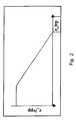
- FIG. 2is a graph of an example of a fuzzy logic control mechanism.
- control loop structureknown from the prior art which contains a PID controller is used for a continuously variable belt drive transmission with the theoretical ratio iv_theor. as command variable, the actual ratio iv as controlled variable and the ratio-change speed as correcting variable.
- the control loop structurealso contains a member which limits the correcting variable ratio-change speed delivered by the PID controller to limit values subject to the design.
- the limit values subject to the designare continuously calculated according to different internal and external parameters.
- control loop structureis enlarged by one other correction member which corrects the resulting pattern error taking into consideration internal and external system variables with reference to a physicomathematical pattern.
- the correction memberis based on methods of the fuzzy logic and uses setting rules such as are also exposed in a correction “by hand.”
- the actual value of the ratio-change speedis compared with the theoretical value and the difference e_ivp is formed.
- the gradient of the ratio-change speed (ratio-change direction) e_ivpp relative to the theoretical valueis determined by differentiation.
- Each field of the tablerepresents one rule with two premises each.
- the control conclusion when the premises prove correctis shown by the plotted numeric value (singleton).
- the control premisesare evaluated by “fuzzy sets” which represent the information of the premises as “diffused amount.”
- fuzzy logic control mechanism shownworks with all the methodical means known from the foundations of the fuzzy logic and which contribute optimally to adapt the control mechanism to the problem posed:
- adjustable operatorsfor linking the premise members (aggregation) and adjustable operators for summarizing the total result (inference).
- the numeric range of the singletonsis kept between +100 and ⁇ 100 (%).
- the input variablesare passed over special filter steps which, together with an adjustable high-stop filtering of the raw signals, also produce a standardization of the value range ( ⁇ 100% . . . +100%).
- One other acceleration out of the resting positionis obtained by introducing a load signal (for example, accelerator pedal or throttle valve) in the control mechanism in a manner such as to induce a derivative reaction of the correction interference.
- a load signalfor example, accelerator pedal or throttle valve
Landscapes
- Engineering & Computer Science (AREA)
- General Engineering & Computer Science (AREA)
- Mechanical Engineering (AREA)
- Control Of Transmission Device (AREA)
Abstract


Description


| E_ivp | ||
| NEGATIVE | POSITIVE | |||
| VERY GREAT | ZERO | VERY GREAT | ||
| POSITIVE | 0 | 50 | 100 | |
| VERY | ||||
| GREAT | ||||
| E_ivp | ZERO | −50 | 10 | 50 |
| p | ||||
| NEGATIVE | −100 | −50 | 0 | |
| VERY | ||||
| GREAT | ||||
| E_ivp = AND E_ivpp = 0 | ||
| ACTIVE | ||
| POS. | 100 | |||
| GREAT | ||||
| iv_theor.- | ZERO | 50 | ||
| iv_actual | ||||
| NEG. | −100 | |||
| GREAT | ||||
Claims (6)


Applications Claiming Priority (2)
| Application Number | Priority Date | Filing Date | Title |
|---|---|---|---|
| DE19908250 | 1999-02-25 | ||
| DE19908250ADE19908250A1 (en) | 1999-02-25 | 1999-02-25 | Transmission ratio regulation for continuous automatic gearbox involves correction element taking account of internal and external system parameters in physical mathematical model |
Publications (1)
| Publication Number | Publication Date |
|---|---|
| US6311113B1true US6311113B1 (en) | 2001-10-30 |
Family
ID=7898895
Family Applications (1)
| Application Number | Title | Priority Date | Filing Date |
|---|---|---|---|
| US09/505,096Expired - Fee RelatedUS6311113B1 (en) | 1999-02-25 | 2000-02-16 | Control method for adjusting the transmission ratio of a CVT |
Country Status (2)
| Country | Link |
|---|---|
| US (1) | US6311113B1 (en) |
| DE (1) | DE19908250A1 (en) |
Cited By (50)
| Publication number | Priority date | Publication date | Assignee | Title |
|---|---|---|---|---|
| US6547694B2 (en)* | 2000-03-17 | 2003-04-15 | Jatco Transtechnology Ltd. | Hydraulic control system for a continuously variable transmission |
| US20040002803A1 (en)* | 2002-06-28 | 2004-01-01 | Jung-Suk Lee | Shift control method and apparatus of an automatic transmission |
| US6721643B1 (en) | 2002-09-23 | 2004-04-13 | General Motors Corporation | Method of controlling a CVT speed ratio |
| US20040085034A1 (en)* | 2002-11-01 | 2004-05-06 | Kuras Brian D. | System and method for controlling a motor |
| US20040235595A1 (en)* | 2001-12-29 | 2004-11-25 | Joachim Luh | Control circuit and method for generating a contol signal for controlling a continuously variable belt transmission |
| US20050107935A1 (en)* | 2003-11-19 | 2005-05-19 | Kai-Uwe Herbster | Ratio control method for a continuously variable transmission |
| US20080300075A1 (en)* | 2007-05-25 | 2008-12-04 | Jtekt Corporation | Oil supply system for motor vehicle |
| US20090112424A1 (en)* | 2007-10-31 | 2009-04-30 | Caterpillar Inc. | Propulsion system with a continuously variable transmission |
| US20100131164A1 (en)* | 2007-02-01 | 2010-05-27 | Fallbrook Technologies Inc. | Systems and methods for control of transmission and/or prime mover |
| US20100262343A1 (en)* | 2007-10-26 | 2010-10-14 | Anders Eriksson | Method for a more efficient use of a combustion engine in a vehicle |
| US20110034284A1 (en)* | 2005-12-30 | 2011-02-10 | Fallbrook Technologies Inc. | Continuously variable transmission |
| TWI386767B (en)* | 2009-04-21 | 2013-02-21 | Univ Shu Te | A Method for Designing Multivariable Proportional Integral Differential Controller |
| US8469853B2 (en) | 2003-02-28 | 2013-06-25 | Fallbrook Intellectual Property Company Llc | Continuously variable transmission |
| US8480529B2 (en) | 2006-06-26 | 2013-07-09 | Fallbrook Intellectual Property Company Llc | Continuously variable transmission |
| US8512195B2 (en) | 2010-03-03 | 2013-08-20 | Fallbrook Intellectual Property Company Llc | Infinitely variable transmissions, continuously variable transmissions, methods, assemblies, subassemblies, and components therefor |
| US8535199B2 (en) | 2008-06-06 | 2013-09-17 | Fallbrook Intellectual Property Company Llc | Infinitely variable transmissions, continuously variable transmissions, methods, assemblies, subassemblies, and components therefor |
| US8550949B2 (en) | 2005-10-28 | 2013-10-08 | Fallbrook Intellectual Property Company Llc | Electromotive drives |
| US8585528B2 (en) | 2007-02-16 | 2013-11-19 | Fallbrook Intellectual Property Company Llc | Infinitely variable transmissions, continuously variable transmissions, methods, assemblies, subassemblies, and components therefor |
| US8622866B2 (en) | 2008-02-29 | 2014-01-07 | Fallbrook Intellectual Property Company Llc | Continuously and/or infinitely variable transmissions and methods therefor |
| US8626409B2 (en) | 2007-12-21 | 2014-01-07 | Fallbrook Intellectual Property Company Llc | Automatic transmissions and methods therefor |
| US8641572B2 (en) | 2008-06-23 | 2014-02-04 | Fallbrook Intellectual Property Company Llc | Continuously variable transmission |
| US8641577B2 (en) | 2007-06-11 | 2014-02-04 | Fallbrook Intellectual Property Company Llc | Continuously variable transmission |
| US8663050B2 (en) | 2009-04-16 | 2014-03-04 | Fallbrook Intellectual Property Company Llc | Continuously variable transmission |
| US8678974B2 (en) | 2008-05-07 | 2014-03-25 | Fallbrook Intellectual Property Company Llc | Assemblies and methods for clamping force generation |
| US8708360B2 (en) | 2005-11-22 | 2014-04-29 | Fallbrook Intellectual Property Company Llc | Continuously variable transmission |
| US8776633B2 (en) | 2006-01-30 | 2014-07-15 | Fallbrook Intellectual Property Company Llc | System for manipulating a continuously variable transmission |
| US8818661B2 (en) | 2008-08-05 | 2014-08-26 | Fallbrook Intellectual Property Company Llc | Methods for control of transmission and prime mover |
| US8845485B2 (en) | 2011-04-04 | 2014-09-30 | Fallbrook Intellectual Property Company Llc | Auxiliary power unit having a continuously variable transmission |
| US8852050B2 (en) | 2008-08-26 | 2014-10-07 | Fallbrook Intellectual Property Company Llc | Continuously variable transmission |
| US8870711B2 (en) | 2008-10-14 | 2014-10-28 | Fallbrook Intellectual Property Company Llc | Continuously variable transmission |
| US8888643B2 (en) | 2010-11-10 | 2014-11-18 | Fallbrook Intellectual Property Company Llc | Continuously variable transmission |
| US8900085B2 (en) | 2007-07-05 | 2014-12-02 | Fallbrook Intellectual Property Company Llc | Continuously variable transmission |
| US8920285B2 (en) | 2004-10-05 | 2014-12-30 | Fallbrook Intellectual Property Company Llc | Continuously variable transmission |
| US8996263B2 (en) | 2007-11-16 | 2015-03-31 | Fallbrook Intellectual Property Company Llc | Controller for variable transmission |
| US9086145B2 (en) | 2006-11-08 | 2015-07-21 | Fallbrook Intellectual Property Company Llc | Clamping force generator |
| US9121464B2 (en) | 2005-12-09 | 2015-09-01 | Fallbrook Intellectual Property Company Llc | Continuously variable transmission |
| US20150307083A1 (en)* | 2014-04-28 | 2015-10-29 | Toyota Jidosha Kabushiki Kaisha | Hybrid vechicle and method of controlling hybrid vehicle |
| US9273760B2 (en) | 2007-04-24 | 2016-03-01 | Fallbrook Intellectual Property Company Llc | Electric traction drives |
| US9371894B2 (en) | 2007-02-12 | 2016-06-21 | Fallbrook Intellectual Property Company Llc | Continuously variable transmissions and methods therefor |
| US20160214602A1 (en)* | 2015-01-27 | 2016-07-28 | Toyota Jidosha Kabushiki Kaisha | Hybrid vehicle |
| US9611921B2 (en) | 2012-01-23 | 2017-04-04 | Fallbrook Intellectual Property Company Llc | Infinitely variable transmissions, continuously variable transmissions, methods, assemblies, subassemblies, and components therefor |
| US9677650B2 (en) | 2013-04-19 | 2017-06-13 | Fallbrook Intellectual Property Company Llc | Continuously variable transmission |
| US9958062B2 (en)* | 2014-03-27 | 2018-05-01 | Jatco Ltd | Control device for continuously variable transmission |
| US10035511B2 (en)* | 2015-07-27 | 2018-07-31 | Cummins Inc. | Method and system for controlling operation of an engine powered device having cyclical duty cycles |
| US10047861B2 (en) | 2016-01-15 | 2018-08-14 | Fallbrook Intellectual Property Company Llc | Systems and methods for controlling rollback in continuously variable transmissions |
| US10458526B2 (en) | 2016-03-18 | 2019-10-29 | Fallbrook Intellectual Property Company Llc | Continuously variable transmissions, systems and methods |
| US11174922B2 (en) | 2019-02-26 | 2021-11-16 | Fallbrook Intellectual Property Company Llc | Reversible variable drives and systems and methods for control in forward and reverse directions |
| US11215268B2 (en) | 2018-11-06 | 2022-01-04 | Fallbrook Intellectual Property Company Llc | Continuously variable transmissions, synchronous shifting, twin countershafts and methods for control of same |
| US11667351B2 (en) | 2016-05-11 | 2023-06-06 | Fallbrook Intellectual Property Company Llc | Systems and methods for automatic configuration and automatic calibration of continuously variable transmissions and bicycles having continuously variable transmission |
| US12442434B2 (en) | 2024-06-04 | 2025-10-14 | Enviolo B.V. | Reversible variable drives and systems and methods for control in forward and reverse directions |
Families Citing this family (3)
| Publication number | Priority date | Publication date | Assignee | Title |
|---|---|---|---|---|
| DE102015203902A1 (en)* | 2015-03-05 | 2016-09-08 | Robert Bosch Gmbh | CVT transmission with improved controllability and control method therefor |
| DE102018000156A1 (en)* | 2018-01-11 | 2019-07-11 | Senvion Gmbh | Method and system for controlling a wind turbine |
| DE102023107193A1 (en)* | 2023-03-22 | 2024-09-26 | Fraunhofer-Gesellschaft zur Förderung der angewandten Forschung eingetragener Verein | Method for adjusting a pressure medium supply for at least one hydraulic actuator and hydraulic system |
Citations (9)
| Publication number | Priority date | Publication date | Assignee | Title |
|---|---|---|---|---|
| US4710879A (en)* | 1986-02-12 | 1987-12-01 | General Motors Corporation | Ratio control system for a continuously variable transmission |
| US4827803A (en)* | 1986-08-20 | 1989-05-09 | Fuji Jukogyo Kabushiki Kaisha | Transmission ratio control system for a continuously variable transmission |
| US4993284A (en)* | 1983-05-27 | 1991-02-19 | Nissan Motor Company, Limited | Control device for vehicular engine continuously variable transmission system |
| US5009127A (en)* | 1988-10-14 | 1991-04-23 | Fuji Jukogyo Kabushiki Kaisha | Transmission ratio control system for a continuously variable transmission |
| US5136495A (en)* | 1985-05-28 | 1992-08-04 | Toyota Jidosha Kabushiki Kaisha | Speed ratio control system and method for a continuously variable transmission for a vehicle |
| US5366416A (en)* | 1992-04-06 | 1994-11-22 | Van Doorne's Transmissie B.V. | Continuously variable transmission with control system |
| DE19606311A1 (en) | 1996-02-21 | 1997-08-28 | Zahnradfabrik Friedrichshafen | Control system for a CVT |
| US5906649A (en)* | 1996-01-20 | 1999-05-25 | Temic Telefunken Microelectronic Gmbh | Procedure for controlling continuous variable transmissions in motor vehicles |
| US5931884A (en)* | 1996-03-07 | 1999-08-03 | Nissan Motor Co., Ltd. | Continuously variable transmission control method and apparatus |
- 1999
- 1999-02-25DEDE19908250Apatent/DE19908250A1/ennot_activeWithdrawn
- 2000
- 2000-02-16USUS09/505,096patent/US6311113B1/ennot_activeExpired - Fee Related
Patent Citations (10)
| Publication number | Priority date | Publication date | Assignee | Title |
|---|---|---|---|---|
| US4993284A (en)* | 1983-05-27 | 1991-02-19 | Nissan Motor Company, Limited | Control device for vehicular engine continuously variable transmission system |
| US5136495A (en)* | 1985-05-28 | 1992-08-04 | Toyota Jidosha Kabushiki Kaisha | Speed ratio control system and method for a continuously variable transmission for a vehicle |
| US4710879A (en)* | 1986-02-12 | 1987-12-01 | General Motors Corporation | Ratio control system for a continuously variable transmission |
| US4827803A (en)* | 1986-08-20 | 1989-05-09 | Fuji Jukogyo Kabushiki Kaisha | Transmission ratio control system for a continuously variable transmission |
| US5009127A (en)* | 1988-10-14 | 1991-04-23 | Fuji Jukogyo Kabushiki Kaisha | Transmission ratio control system for a continuously variable transmission |
| US5366416A (en)* | 1992-04-06 | 1994-11-22 | Van Doorne's Transmissie B.V. | Continuously variable transmission with control system |
| US5906649A (en)* | 1996-01-20 | 1999-05-25 | Temic Telefunken Microelectronic Gmbh | Procedure for controlling continuous variable transmissions in motor vehicles |
| DE19606311A1 (en) | 1996-02-21 | 1997-08-28 | Zahnradfabrik Friedrichshafen | Control system for a CVT |
| US5967918A (en) | 1996-02-21 | 1999-10-19 | Zf Friedrichshafen Ag | Regulating system for a continuously variable transmission (CVT) |
| US5931884A (en)* | 1996-03-07 | 1999-08-03 | Nissan Motor Co., Ltd. | Continuously variable transmission control method and apparatus |
Cited By (130)
| Publication number | Priority date | Publication date | Assignee | Title |
|---|---|---|---|---|
| US6547694B2 (en)* | 2000-03-17 | 2003-04-15 | Jatco Transtechnology Ltd. | Hydraulic control system for a continuously variable transmission |
| US7121967B2 (en)* | 2001-12-29 | 2006-10-17 | Robert Bosch Gmbh | Control circuit and method for generating a control signal for controlling a continuously variable belt transmission |
| US20040235595A1 (en)* | 2001-12-29 | 2004-11-25 | Joachim Luh | Control circuit and method for generating a contol signal for controlling a continuously variable belt transmission |
| US20040002803A1 (en)* | 2002-06-28 | 2004-01-01 | Jung-Suk Lee | Shift control method and apparatus of an automatic transmission |
| US6882919B2 (en)* | 2002-06-28 | 2005-04-19 | Hyundai Motor Company | Shift control method and apparatus of an automatic transmission |
| US6721643B1 (en) | 2002-09-23 | 2004-04-13 | General Motors Corporation | Method of controlling a CVT speed ratio |
| US20040085034A1 (en)* | 2002-11-01 | 2004-05-06 | Kuras Brian D. | System and method for controlling a motor |
| US8628443B2 (en) | 2003-02-28 | 2014-01-14 | Fallbrook Intellectual Property Company Llc | Continuously variable transmission |
| US9732848B2 (en) | 2003-02-28 | 2017-08-15 | Fallbrook Intellectual Property Company Llc | Continuously variable transmission |
| US10428939B2 (en) | 2003-02-28 | 2019-10-01 | Fallbrook Intellectual Property Company Llc | Continuously variable transmission |
| US8469853B2 (en) | 2003-02-28 | 2013-06-25 | Fallbrook Intellectual Property Company Llc | Continuously variable transmission |
| US9046158B2 (en) | 2003-02-28 | 2015-06-02 | Fallbrook Intellectual Property Company Llc | Continuously variable transmission |
| US20080004781A1 (en)* | 2003-11-19 | 2008-01-03 | Zf Friedrichshafen Ag | Ratio control method for a continuously variable transmission |
| US20050107935A1 (en)* | 2003-11-19 | 2005-05-19 | Kai-Uwe Herbster | Ratio control method for a continuously variable transmission |
| US7831365B2 (en) | 2003-11-19 | 2010-11-09 | Zf Friedrichshafen Ag | Ratio control method for a continuously variable transmission |
| US8920285B2 (en) | 2004-10-05 | 2014-12-30 | Fallbrook Intellectual Property Company Llc | Continuously variable transmission |
| US10036453B2 (en) | 2004-10-05 | 2018-07-31 | Fallbrook Intellectual Property Company Llc | Continuously variable transmission |
| US9022889B2 (en) | 2005-10-28 | 2015-05-05 | Fallbrook Intellectual Property Company Llc | Electromotive drives |
| US8550949B2 (en) | 2005-10-28 | 2013-10-08 | Fallbrook Intellectual Property Company Llc | Electromotive drives |
| US9506562B2 (en) | 2005-10-28 | 2016-11-29 | Fallbrook Intellectual Property Company Llc | Electromotive drives |
| US9950608B2 (en) | 2005-10-28 | 2018-04-24 | Fallbrook Intellectual Property Company Llc | Electromotive drives |
| US8708360B2 (en) | 2005-11-22 | 2014-04-29 | Fallbrook Intellectual Property Company Llc | Continuously variable transmission |
| US9341246B2 (en) | 2005-11-22 | 2016-05-17 | Fallbrook Intellectual Property Company Llc | Continuously variable transmission |
| US10711869B2 (en) | 2005-11-22 | 2020-07-14 | Fallbrook Intellectual Property Company Llc | Continuously variable transmission |
| US9709138B2 (en) | 2005-11-22 | 2017-07-18 | Fallbrook Intellectual Property Company Llc | Continuously variable transmission |
| US9121464B2 (en) | 2005-12-09 | 2015-09-01 | Fallbrook Intellectual Property Company Llc | Continuously variable transmission |
| US10208840B2 (en) | 2005-12-09 | 2019-02-19 | Fallbrook Intellectual Property Company Llc | Continuously variable transmission |
| US11454303B2 (en) | 2005-12-09 | 2022-09-27 | Fallbrook Intellectual Property Company Llc | Continuously variable transmission |
| US11598397B2 (en) | 2005-12-30 | 2023-03-07 | Fallbrook Intellectual Property Company Llc | Continuously variable gear transmission |
| US20110034284A1 (en)* | 2005-12-30 | 2011-02-10 | Fallbrook Technologies Inc. | Continuously variable transmission |
| US8506452B2 (en)* | 2005-12-30 | 2013-08-13 | Fallbrook Intellectual Property Company Llc | Continuously variable transmission |
| US9683638B2 (en) | 2005-12-30 | 2017-06-20 | Fallbrook Intellectual Property Company Llc | Continuously variable gear transmission |
| US8776633B2 (en) | 2006-01-30 | 2014-07-15 | Fallbrook Intellectual Property Company Llc | System for manipulating a continuously variable transmission |
| US8480529B2 (en) | 2006-06-26 | 2013-07-09 | Fallbrook Intellectual Property Company Llc | Continuously variable transmission |
| US9726282B2 (en) | 2006-06-26 | 2017-08-08 | Fallbrook Intellectual Property Company Llc | Continuously variable transmission |
| US9017207B2 (en) | 2006-06-26 | 2015-04-28 | Fallbrook Intellectual Property Company Llc | Continuously variable transmission |
| US9086145B2 (en) | 2006-11-08 | 2015-07-21 | Fallbrook Intellectual Property Company Llc | Clamping force generator |
| US9328807B2 (en)* | 2007-02-01 | 2016-05-03 | Fallbrook Intellectual Property Company Llc | Systems and methods for control of transmission and/or prime mover |
| US20140257650A1 (en)* | 2007-02-01 | 2014-09-11 | Fallbrook Intellectual Property Company Llc | Systems and methods for control of transmission and/or prime mover |
| US9676391B2 (en)* | 2007-02-01 | 2017-06-13 | Fallbrook Intellectual Property Company Llc | Systems and methods for control of transmission and/or prime mover |
| US20180148055A1 (en)* | 2007-02-01 | 2018-05-31 | Fallbrook Intellectual Property Company Llc | Systems and methods for control of transmission and/or prime mover |
| US8738255B2 (en)* | 2007-02-01 | 2014-05-27 | Fallbrook Intellectual Property Company Llc | Systems and methods for control of transmission and/or prime mover |
| US20100131164A1 (en)* | 2007-02-01 | 2010-05-27 | Fallbrook Technologies Inc. | Systems and methods for control of transmission and/or prime mover |
| US10703372B2 (en)* | 2007-02-01 | 2020-07-07 | Fallbrook Intellectual Property Company Llc | Systems and methods for control of transmission and/or prime mover |
| US20160244063A1 (en)* | 2007-02-01 | 2016-08-25 | Fallbrook Intellectual Property Company Llc | Systems and methods for control of transmission and/or prime mover |
| US9878719B2 (en)* | 2007-02-01 | 2018-01-30 | Fallbrook Intellectual Property Company Llc | Systems and methods for control of transmission and/or prime mover |
| US10260607B2 (en) | 2007-02-12 | 2019-04-16 | Fallbrook Intellectual Property Company Llc | Continuously variable transmissions and methods therefor |
| US9371894B2 (en) | 2007-02-12 | 2016-06-21 | Fallbrook Intellectual Property Company Llc | Continuously variable transmissions and methods therefor |
| US8585528B2 (en) | 2007-02-16 | 2013-11-19 | Fallbrook Intellectual Property Company Llc | Infinitely variable transmissions, continuously variable transmissions, methods, assemblies, subassemblies, and components therefor |
| US10094453B2 (en) | 2007-02-16 | 2018-10-09 | Fallbrook Intellectual Property Company Llc | Infinitely variable transmissions, continuously variable transmissions, methods, assemblies, subassemblies, and components therefor |
| US9239099B2 (en) | 2007-02-16 | 2016-01-19 | Fallbrook Intellectual Property Company Llc | Infinitely variable transmissions, continuously variable transmissions, methods, assemblies, subassemblies, and components therefor |
| US9574643B2 (en) | 2007-04-24 | 2017-02-21 | Fallbrook Intellectual Property Company Llc | Electric traction drives |
| US10056811B2 (en) | 2007-04-24 | 2018-08-21 | Fallbrook Intellectual Property Company Llc | Electric traction drives |
| US9273760B2 (en) | 2007-04-24 | 2016-03-01 | Fallbrook Intellectual Property Company Llc | Electric traction drives |
| US20080300075A1 (en)* | 2007-05-25 | 2008-12-04 | Jtekt Corporation | Oil supply system for motor vehicle |
| US9945456B2 (en) | 2007-06-11 | 2018-04-17 | Fallbrook Intellectual Property Company Llc | Continuously variable transmission |
| US8641577B2 (en) | 2007-06-11 | 2014-02-04 | Fallbrook Intellectual Property Company Llc | Continuously variable transmission |
| US8900085B2 (en) | 2007-07-05 | 2014-12-02 | Fallbrook Intellectual Property Company Llc | Continuously variable transmission |
| US9869388B2 (en) | 2007-07-05 | 2018-01-16 | Fallbrook Intellectual Property Company Llc | Continuously variable transmission |
| US10260629B2 (en) | 2007-07-05 | 2019-04-16 | Fallbrook Intellectual Property Company Llc | Continuously variable transmission |
| US10330029B2 (en)* | 2007-10-26 | 2019-06-25 | Volvo Lastvagnar Ab | Method for a more efficient use of a combustion engine in a vehicle |
| US20100262343A1 (en)* | 2007-10-26 | 2010-10-14 | Anders Eriksson | Method for a more efficient use of a combustion engine in a vehicle |
| US8321105B2 (en) | 2007-10-31 | 2012-11-27 | Caterpillar Inc. | Propulsion system with a continuously variable transmission |
| US8571774B2 (en) | 2007-10-31 | 2013-10-29 | Caterpillar Inc. | Propulsion system with a continuously variable transmission |
| US20090112424A1 (en)* | 2007-10-31 | 2009-04-30 | Caterpillar Inc. | Propulsion system with a continuously variable transmission |
| US11125329B2 (en) | 2007-11-16 | 2021-09-21 | Fallbrook Intellectual Property Company Llc | Controller for variable transmission |
| US10100927B2 (en) | 2007-11-16 | 2018-10-16 | Fallbrook Intellectual Property Company Llc | Controller for variable transmission |
| US8996263B2 (en) | 2007-11-16 | 2015-03-31 | Fallbrook Intellectual Property Company Llc | Controller for variable transmission |
| US8626409B2 (en) | 2007-12-21 | 2014-01-07 | Fallbrook Intellectual Property Company Llc | Automatic transmissions and methods therefor |
| US9739375B2 (en) | 2007-12-21 | 2017-08-22 | Fallbrook Intellectual Property Company Llc | Automatic transmissions and methods therefor |
| US9249880B2 (en) | 2007-12-21 | 2016-02-02 | Fallbrook Intellectual Property Company Llc | Automatic transmissions and methods therefor |
| US10704687B2 (en) | 2007-12-21 | 2020-07-07 | Fallbrook Intellectual Property Company Llc | Automatic transmissions and methods therefor |
| US8622866B2 (en) | 2008-02-29 | 2014-01-07 | Fallbrook Intellectual Property Company Llc | Continuously and/or infinitely variable transmissions and methods therefor |
| US9850993B2 (en) | 2008-02-29 | 2017-12-26 | Fallbrook Intellectual Property Company Llc | Continuously and/or infinitely variable transmissions and methods therefor |
| US9182018B2 (en) | 2008-02-29 | 2015-11-10 | Fallbrook Intellectual Property Company Llc | Continuously and/or infinitely variable transmissions and methods therefor |
| US8678974B2 (en) | 2008-05-07 | 2014-03-25 | Fallbrook Intellectual Property Company Llc | Assemblies and methods for clamping force generation |
| US9618100B2 (en) | 2008-05-07 | 2017-04-11 | Fallbrook Intellectual Property Company Llc | Assemblies and methods for clamping force generation |
| US8790214B2 (en) | 2008-06-06 | 2014-07-29 | Fallbrook Intellectual Property Company Llc | Infinitely variable transmissions, continuously variable transmissions, methods, assemblies, subassemblies, and components therefor |
| US8535199B2 (en) | 2008-06-06 | 2013-09-17 | Fallbrook Intellectual Property Company Llc | Infinitely variable transmissions, continuously variable transmissions, methods, assemblies, subassemblies, and components therefor |
| US9683640B2 (en) | 2008-06-06 | 2017-06-20 | Fallbrook Intellectual Property Company Llc | Infinitely variable transmissions, continuously variable transmissions, methods, assemblies, subassemblies, and components therefor |
| US10634224B2 (en) | 2008-06-06 | 2020-04-28 | Fallbrook Intellectual Property Company Llc | Infinitely variable transmissions, continuously variable transmissions, methods, assemblies, subassemblies, and components therefor |
| US9074674B2 (en) | 2008-06-23 | 2015-07-07 | Fallbrook Intellectual Property Company Llc | Continuously variable transmission |
| US8641572B2 (en) | 2008-06-23 | 2014-02-04 | Fallbrook Intellectual Property Company Llc | Continuously variable transmission |
| US9528561B2 (en) | 2008-06-23 | 2016-12-27 | Fallbrook Intellectual Property Company Llc | Continuously variable transmission |
| US10066713B2 (en) | 2008-06-23 | 2018-09-04 | Fallbrook Intellectual Property Company Llc | Continuously variable transmission |
| US9365203B2 (en) | 2008-08-05 | 2016-06-14 | Fallbrook Intellectual Property Company Llc | Systems and methods for control of transmission and/or prime mover |
| US9878717B2 (en) | 2008-08-05 | 2018-01-30 | Fallbrook Intellectual Property Company Llc | Systems and methods for control of transmission and/or prime mover |
| US8818661B2 (en) | 2008-08-05 | 2014-08-26 | Fallbrook Intellectual Property Company Llc | Methods for control of transmission and prime mover |
| US9903450B2 (en) | 2008-08-26 | 2018-02-27 | Fallbrook Intellectual Property Company Llc | Continuously variable transmission |
| US10704657B2 (en) | 2008-08-26 | 2020-07-07 | Fallbrook Intellectual Property Company Llc | Continuously variable transmission |
| US8852050B2 (en) | 2008-08-26 | 2014-10-07 | Fallbrook Intellectual Property Company Llc | Continuously variable transmission |
| US10253880B2 (en) | 2008-10-14 | 2019-04-09 | Fallbrook Intellectual Property Company Llc | Continuously variable transmission |
| US8870711B2 (en) | 2008-10-14 | 2014-10-28 | Fallbrook Intellectual Property Company Llc | Continuously variable transmission |
| US9574642B2 (en) | 2008-10-14 | 2017-02-21 | Fallbrook Intellectual Property Company Llc | Continuously variable transmission |
| US10746270B2 (en) | 2009-04-16 | 2020-08-18 | Fallbrook Intellectual Property Company Llc | Continuously variable transmission |
| US9279482B2 (en) | 2009-04-16 | 2016-03-08 | Fallbrook Intellectual Property Company Llc | Continuously variable transmission |
| US8663050B2 (en) | 2009-04-16 | 2014-03-04 | Fallbrook Intellectual Property Company Llc | Continuously variable transmission |
| US9920823B2 (en) | 2009-04-16 | 2018-03-20 | Fallbrook Intellectual Property Company Llc | Continuously variable transmission |
| TWI386767B (en)* | 2009-04-21 | 2013-02-21 | Univ Shu Te | A Method for Designing Multivariable Proportional Integral Differential Controller |
| US8721485B2 (en) | 2010-03-03 | 2014-05-13 | Fallbrook Intellectual Property Company Llc | Infinitely variable transmissions, continuously variable transmissions, methods, assemblies, subassemblies, and components therefor |
| US10066712B2 (en) | 2010-03-03 | 2018-09-04 | Fallbrook Intellectual Property Company Llc | Infinitely variable transmissions, continuously variable transmissions, methods, assemblies, subassemblies, and components therefor |
| US8512195B2 (en) | 2010-03-03 | 2013-08-20 | Fallbrook Intellectual Property Company Llc | Infinitely variable transmissions, continuously variable transmissions, methods, assemblies, subassemblies, and components therefor |
| US9360089B2 (en) | 2010-03-03 | 2016-06-07 | Fallbrook Intellectual Property Company Llc | Infinitely variable transmissions, continuously variable transmissions, methods, assemblies, subassemblies, and components therefor |
| US8888643B2 (en) | 2010-11-10 | 2014-11-18 | Fallbrook Intellectual Property Company Llc | Continuously variable transmission |
| US10197147B2 (en) | 2010-11-10 | 2019-02-05 | Fallbrook Intellectual Property Company Llc | Continuously variable transmission |
| US9291251B2 (en) | 2010-11-10 | 2016-03-22 | Fallbrook Intellectual Property Company Llc | Continuously variable transmission |
| US8845485B2 (en) | 2011-04-04 | 2014-09-30 | Fallbrook Intellectual Property Company Llc | Auxiliary power unit having a continuously variable transmission |
| US10428915B2 (en) | 2012-01-23 | 2019-10-01 | Fallbrook Intellectual Property Company Llc | Infinitely variable transmissions, continuously variable transmissions, methods, assemblies, subassemblies, and components therefor |
| US9611921B2 (en) | 2012-01-23 | 2017-04-04 | Fallbrook Intellectual Property Company Llc | Infinitely variable transmissions, continuously variable transmissions, methods, assemblies, subassemblies, and components therefor |
| US10323732B2 (en) | 2013-04-19 | 2019-06-18 | Fallbrook Intellectual Property Company Llc | Continuously variable transmission |
| US9677650B2 (en) | 2013-04-19 | 2017-06-13 | Fallbrook Intellectual Property Company Llc | Continuously variable transmission |
| US9958062B2 (en)* | 2014-03-27 | 2018-05-01 | Jatco Ltd | Control device for continuously variable transmission |
| US20150307083A1 (en)* | 2014-04-28 | 2015-10-29 | Toyota Jidosha Kabushiki Kaisha | Hybrid vechicle and method of controlling hybrid vehicle |
| US9469292B2 (en)* | 2014-04-28 | 2016-10-18 | Toyota Jidosha Kabushiki Kaisha | Hybrid vehicle and method of controlling hybrid vehicle |
| US9834202B2 (en)* | 2015-01-27 | 2017-12-05 | Toyota Jidosha Kabushiki Kaisha | Hybrid vehicle |
| US20160214602A1 (en)* | 2015-01-27 | 2016-07-28 | Toyota Jidosha Kabushiki Kaisha | Hybrid vehicle |
| US10035511B2 (en)* | 2015-07-27 | 2018-07-31 | Cummins Inc. | Method and system for controlling operation of an engine powered device having cyclical duty cycles |
| US11306818B2 (en) | 2016-01-15 | 2022-04-19 | Fallbrook Intellectual Property Company Llc | Systems and methods for controlling rollback in continuously variable transmissions |
| US10920882B2 (en) | 2016-01-15 | 2021-02-16 | Fallbrook Intellectual Property Company Llc | Systems and methods for controlling rollback in continuously variable transmissions |
| US10047861B2 (en) | 2016-01-15 | 2018-08-14 | Fallbrook Intellectual Property Company Llc | Systems and methods for controlling rollback in continuously variable transmissions |
| US10458526B2 (en) | 2016-03-18 | 2019-10-29 | Fallbrook Intellectual Property Company Llc | Continuously variable transmissions, systems and methods |
| US11667351B2 (en) | 2016-05-11 | 2023-06-06 | Fallbrook Intellectual Property Company Llc | Systems and methods for automatic configuration and automatic calibration of continuously variable transmissions and bicycles having continuously variable transmission |
| US12145690B2 (en) | 2016-05-11 | 2024-11-19 | Enviolo B.V. | Systems and methods for automatic configuration and automatic calibration of continuously variable transmissions and bicycles having continuously variable transmissions |
| US11215268B2 (en) | 2018-11-06 | 2022-01-04 | Fallbrook Intellectual Property Company Llc | Continuously variable transmissions, synchronous shifting, twin countershafts and methods for control of same |
| US11624432B2 (en) | 2018-11-06 | 2023-04-11 | Fallbrook Intellectual Property Company Llc | Continuously variable transmissions, synchronous shifting, twin countershafts and methods for control of same |
| US12173778B2 (en) | 2018-11-06 | 2024-12-24 | Enviolo B.V. | Continuously variable transmissions, synchronous shifting, twin countershafts and methods for control of same |
| US11174922B2 (en) | 2019-02-26 | 2021-11-16 | Fallbrook Intellectual Property Company Llc | Reversible variable drives and systems and methods for control in forward and reverse directions |
| US11530739B2 (en) | 2019-02-26 | 2022-12-20 | Fallbrook Intellectual Property Company Llc | Reversible variable drives and systems and methods for control in forward and reverse directions |
| US12000458B2 (en) | 2019-02-26 | 2024-06-04 | Fallbrook Intellectual Property Company Llc | Reversible variable drives and systems and methods for control in forward and reverse directions |
| US12442434B2 (en) | 2024-06-04 | 2025-10-14 | Enviolo B.V. | Reversible variable drives and systems and methods for control in forward and reverse directions |
Also Published As
| Publication number | Publication date |
|---|---|
| DE19908250A1 (en) | 2000-08-31 |
Similar Documents
| Publication | Publication Date | Title |
|---|---|---|
| US6311113B1 (en) | Control method for adjusting the transmission ratio of a CVT | |
| US4811225A (en) | Ratio control technique for continuously variable transmission | |
| US8280597B2 (en) | Control apparatus of automatic transmission | |
| US5168778A (en) | CVT downshift control strategy to minimize slip at the drive pulley | |
| CN102414485B (en) | belt-based continuously variable transmission control device and control method thereof | |
| US4649486A (en) | Control method for continuously variable transmission or the like | |
| RU2498132C2 (en) | Device and method of control over belt-type stepless transmission | |
| JPS62116320A (en) | Control unit for continuously variable transmission | |
| JPH08296708A (en) | Controller for continuously variable automatic transmission | |
| EP0410451B1 (en) | Feedback ratio change control for transmission | |
| JP2005273850A (en) | Shift control device of belt type continuously variable transmission | |
| JP3161326B2 (en) | Control device for continuously variable automatic transmission | |
| JP3211714B2 (en) | Gear ratio control device for continuously variable transmission | |
| JPH04171354A (en) | Controller for continuously variable transmission | |
| JPH0830529B2 (en) | Controller for continuously variable transmission | |
| US5213012A (en) | Downshift with power in continuously variable transmission | |
| US6067493A (en) | Speed change ratio controller for continuously variable transmission | |
| JPS63106146A (en) | Control unit for continuously variable transmission | |
| US6542803B1 (en) | Method for determining adjusting speeds in a continuously variable transmission | |
| JP6840445B2 (en) | Shift control device for belt-type continuously variable transmission | |
| JPH03181659A (en) | Controller for continuously variable transmission | |
| JP3944042B2 (en) | Hydraulic pressure reduction rate limiting device for V-belt type continuously variable transmission | |
| US6484084B1 (en) | Method and device for controlling and regulating a coupling | |
| JP2864722B2 (en) | Transmission control device for vehicle transmission | |
| US6604039B2 (en) | Control of toroidal continuously variable transmission |
Legal Events
| Date | Code | Title | Description |
|---|---|---|---|
| AS | Assignment | Owner name:ZF BATAVIA, L.L.C., OHIO Free format text:ASSIGNMENT OF ASSIGNORS INTEREST;ASSIGNORS:DANZ, WOLFGANG;PIEPENBRINK, ANDREAS;SCHWENGER, ANDREAS;REEL/FRAME:010575/0744 Effective date:20000119 | |
| FEPP | Fee payment procedure | Free format text:PAYOR NUMBER ASSIGNED (ORIGINAL EVENT CODE: ASPN); ENTITY STATUS OF PATENT OWNER: LARGE ENTITY | |
| AS | Assignment | Owner name:ZF TRANSMISSION TECHNOLOGIES, L.L.C., OHIO Free format text:ASSIGNMENT OF ASSIGNORS INTEREST;ASSIGNOR:ZF BATAVIA, L.L.C.;REEL/FRAME:014788/0901 Effective date:20031120 Owner name:ZF TRANSMISSION TECHNOLOGIES, L.L.C., OHIO Free format text:ASSIGNMENT OF ASSIGNORS INTEREST;ASSIGNOR:ZF BATAVIA, L.L.C.;REEL/FRAME:015972/0924 Effective date:20031120 | |
| FPAY | Fee payment | Year of fee payment:4 | |
| REMI | Maintenance fee reminder mailed | ||
| LAPS | Lapse for failure to pay maintenance fees | ||
| STCH | Information on status: patent discontinuation | Free format text:PATENT EXPIRED DUE TO NONPAYMENT OF MAINTENANCE FEES UNDER 37 CFR 1.362 | |
| FP | Lapsed due to failure to pay maintenance fee | Effective date:20091030 |