US6311081B1 - Low power operation in a radiotelephone - Google Patents
Low power operation in a radiotelephoneDownload PDFInfo
- Publication number
- US6311081B1 US6311081B1US09/396,720US39672099AUS6311081B1US 6311081 B1US6311081 B1US 6311081B1US 39672099 AUS39672099 AUS 39672099AUS 6311081 B1US6311081 B1US 6311081B1
- Authority
- US
- United States
- Prior art keywords
- radiotelephone
- duration
- timing
- sleep mode
- clock
- Prior art date
- Legal status (The legal status is an assumption and is not a legal conclusion. Google has not performed a legal analysis and makes no representation as to the accuracy of the status listed.)
- Expired - Lifetime
Links
Images


Classifications
- H—ELECTRICITY
- H04—ELECTRIC COMMUNICATION TECHNIQUE
- H04W—WIRELESS COMMUNICATION NETWORKS
- H04W52/00—Power management, e.g. Transmission Power Control [TPC] or power classes
- H04W52/02—Power saving arrangements
- H04W52/0209—Power saving arrangements in terminal devices
- H04W52/0261—Power saving arrangements in terminal devices managing power supply demand, e.g. depending on battery level
- H04W52/0287—Power saving arrangements in terminal devices managing power supply demand, e.g. depending on battery level changing the clock frequency of a controller in the equipment
- H04W52/0293—Power saving arrangements in terminal devices managing power supply demand, e.g. depending on battery level changing the clock frequency of a controller in the equipment having a sub-controller with a low clock frequency switching on and off a main controller with a high clock frequency
- Y—GENERAL TAGGING OF NEW TECHNOLOGICAL DEVELOPMENTS; GENERAL TAGGING OF CROSS-SECTIONAL TECHNOLOGIES SPANNING OVER SEVERAL SECTIONS OF THE IPC; TECHNICAL SUBJECTS COVERED BY FORMER USPC CROSS-REFERENCE ART COLLECTIONS [XRACs] AND DIGESTS
- Y02—TECHNOLOGIES OR APPLICATIONS FOR MITIGATION OR ADAPTATION AGAINST CLIMATE CHANGE
- Y02D—CLIMATE CHANGE MITIGATION TECHNOLOGIES IN INFORMATION AND COMMUNICATION TECHNOLOGIES [ICT], I.E. INFORMATION AND COMMUNICATION TECHNOLOGIES AIMING AT THE REDUCTION OF THEIR OWN ENERGY USE
- Y02D30/00—Reducing energy consumption in communication networks
- Y02D30/70—Reducing energy consumption in communication networks in wireless communication networks
Definitions
- the present inventionrelates generally to reducing power consumption in portable electronic devices such as radiotelephones. More particularly, the present invention relates to controlling the duration of a low-power sleep mode in a radiotelephone.
- a radiotelephoneis a mobile or portable radio which provides two-way radio communication with fixed radio equipment in a radiotelephone system. To improve portability and user convenience, the radiotelephone is powered by a rechargeable battery.
- RadiotelephonesOne design goal for radiotelephones is minimization of power consumption from the battery. This permits use of physically smaller, lighter batteries. Further, power consumption reduction extends the operating time of the radiotelephone. Reduced power consumption is very important in a consumer product such as a radio telephone.
- Radiotelephonesmust be synchronized with the timing of the system in which they operate. Synchronization is necessary, for example to locate and read a paging channel broadcast by the system to indicate an incoming call for the radiotelephone. Thus, there is a need to retain or recover timing information even while in the low-power sleep mode.
- a radiotelephoneaccommodates the varying speed at which its circuits wake up from the sleep mode.
- a microprocessor or other hardware circuitis used to first sense the temperature of the sleep timer or sleeping hardware. This temperature information is used to program the sleep timer. Circuitry that needs a longer time to return to stable operation on power-up will be started first. This permits most circuitry to remain powered down as long as possible.
- the sleep modeuses a special sleep timer to wake up the timing generator at the end of a sleep cycle.
- the sleep modeuses a primary clock and a secondary clock.
- the primary clockis a high-frequency, high-precision clock while the secondary clock is a low-frequency, lower-precision clock generated by a low-power oscillator.
- the sleep timercounts a number of secondary clock pulses to measure the length of the sleep period.
- the secondary clock pulsesare padded with a programmable number of primary clock pulses to achieve an accurate sleep period.
- FIG. 1is a block diagram of a radiotelephone system
- FIG. 2is a block diagram of a portion of the radiotelephone illustrated in FIG. 1;
- FIG. 3, FIG. 4 and FIG. 5are timing diagrams illustrating operation of a sleep timer of the radiotelephone of FIG. 2;
- FIGS. 6 a and 6 bare a flow diagram illustrating a method of operating a radiotelephone.
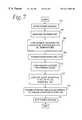
- FIG. 7is a flow diagram illustrating a method of operating a radiotelephone.
- FIG. 1is a block diagram illustrating a radiotelephone system 100 .
- the radiotelephone system 100includes a plurality of base stations such as base station 102 which may be in radiocommunication with a radiotelephone such as radiotelephone 104 .
- the base station 102provides control signals including timing information to allow the radiotelephone 104 to be synchronized with the base station 102 and other fixed components of the system 100 .
- the system 100is a cellular telephone system in accordance with a digital cellular standard, such as IS-136 of IS-136 published by the Telecommunications Industry Association/Electronic Industry Association and commonly referred to as TDMA or DAMPS.
- the system 100may be the Global System for Mobile Communication, or GSM or other systems.
- the radiotelephone 104is a portable radiotelephone such as a cellular telephone.
- the radiotelephone 104includes a receiver circuit 108 , a control circuit 110 , a transmitter 112 , a timing generator 114 , an oscillator 116 , a synthesizer 118 , a memory 120 and a user interface 122 .
- Operating power for the radiotelephone 104is provided by a rechargeable battery 124 .
- Radio signals received from the base station 102are detected at the antenna 106 and converted to digital data for further processing by the received circuit 108 .
- the control circuit 110controls overall operation of the radiotelephone 104 , in conjunction with data and instructions stored in the memory 120 .
- the transmitter circuit 112modulates a carrier signal which is impressed upon the antenna 106 for transmission to the base station.
- the timing generator 114controls all timing of the radiotelephone 104 , including the air interface.
- the timing generator 114operates in response to clocking signals provided by the oscillator 116 .
- the synthesizer 118provides the necessary signals for modulation and demodulation in the transmitter circuit 112 and receiver circuit 108 respectively.
- the user interface 122permits user control of the radiotelephone 104 .
- the user interface 122includes a speaker and microphone, and a keypad and display.
- FIG. 2is an operational block diagram of a portion of the radiotelephone 104 of FIG. 1 .
- the radiotelephone 104includes a processor 202 , an oscillator circuit 204 , a second oscillator circuit 206 , a sleep controller 208 , a timing generator 210 and a synthesizer 212 .
- the processor 202controls operation of the radiotelephone 104 and in one embodiment is implemented as an Advanced Risc (Reduced Instruction Set Computer) Machine.
- the processor 202operates in response to data and instructions stored in the processor 202 and in associated memory.
- the processor 202implements a variety of functions. One such function is a software timer 214 .
- the processor 202further implements a temperature sensor 203 . Temperature sensitivity may be accomplished by any suitable circuit, device or software.
- the temperature sensor 203provides an indication of the current temperature of the radiotelephone 104 .
- the processor 202may use this indication for subsequent processing.
- the first oscillator circuit 204includes a temperature compensated crystal oscillator 220 , a buffer circuit 222 , and a voltage regulator 226 .
- the temperature controlled crystal oscillator 220provides an oscillating signal at a substantially constant, first predetermined frequency. In one exemplary embodiment, this frequency is 19.44 MHz.
- the buffer circuit 222receives the oscillating signal and buffers the signal for transmission to other circuits. The buffer circuit 222 performs functions such as signal squaring.
- the voltage regulator 226provides a voltage which is substantially constant and compensated against variations in temperature and supply voltage.
- the voltage regulator circuit 226has a control input for receiving a control signal from the processor 202 . In response to the control signal, the voltage regulator 226 may be switched between a normal mode and a low-power sleep mode.
- the second oscillator circuit 206includes a second oscillator 232 .
- the second oscillator 232provides a substantially constant second predetermined frequency oscillating signal. In the illustrated example, the signal has a frequency of 32,768 Hz.
- the second oscillator 232generates the oscillating signal and provides the oscillating signal to the sleep controller 208 .
- the oscillator 232has a control input for receiving a control signal from the processor 202 . In response to a control signal, the oscillator 232 may be powered down to a low-power sleep mode.
- the sleep control circuit 208controls entry and exit from the low power sleep mode by the radiotelephone 104 .
- the sleep control circuit 208includes a switch 240 which selects between the output of the primary oscillator circuit 204 and the secondary oscillator circuit 206 .
- the switch 240may be controlled by software and may be any suitable switching circuit implemented in the radiotelephone 104 .
- the switched signalis provided to the microprocessor 202 and to other portions of the radiotelephone 104 as a master clock signal.
- the primary oscillator signalhaving a relatively high frequency such as 19.44 MHz, is provided as the master clock signal.
- the lower frequency signal from the second oscillator circuit 206is provided with the frequency of, for example, 32,768 Hz.
- the timing generator 210provides timing signals for other portions of the radiotelephone 104 .
- the timing generator 210provides timing signals required for synchronization of timing of the radiotelephone 104 with timing of the radiotelephone system in which the radiotelephone 104 operates.
- the radiotelephone systemis a time division multiple access (TDMA) system
- the radiotelephone 104is assigned time slots of a TDMA frame for communicating with a base station in the system.
- Other similar radiotelephonesare assigned other time slots in the frame.
- the timing generator 210provides a variety of control signals. Among these is a synchronization signal labeled Sync in FIG. 2 . Further, the timing generator 210 receives a signal labeled Halt from the sleep controller 208 . By asserting the Halt signal, the timing generator enters a low-power sleep mode to reduce power consumption in the radiotelephone 104 .
- the synthesizer 212provides oscillator signals for modulation and demodulation during radio communication with a remote base station.
- the synthesizerincludes a voltage regulator 242 which provides a substantially constant voltage for operation of the synthesizer 212 .
- the radiotelephone 104contains the timing generator 210 which generates different events necessary for the radiotelephone 104 to maintain radio interface timing.
- the eventsrepeat with a certain period, usually equal to one TDMA frame. Typically, this frame period is 20 ms. If it is known in advance that no communication will take place over the radio interface for, for example, the next two frames, it is possible to shut down the radiotelephone for that period of time to conserve power. To maximize power savings it is desirable to turn off the high-frequency primary clock. However the timing generator uses that clock for event timing and thus radio interface timing would be lost.
- One solution to this problemis to have another means of accurately timing a frame period so that the timing generator can be stopped for an integer number of periods and then restarted without losing synchronization.
- the illustrated embodimentprovides a sleep mode which uses a special sleep timer to wake up the timing generator at the end of a sleep cycle.
- the sleep timercounts a number of secondary clock pulses to measure the length of the sleep period.
- the secondary clock pulsesare padded with a programmable number of primary clock pulses to achieve an accurate sleep period.
- the primary clock frequencyis 19.44 MHz
- the secondary clock frequencyis 32768 Hz
- a sleep cyclestarts on a primary clock period. Since the primary and secondary clocks are un-synchronized, it may take between zero and one secondary clock period before the start of the first period of the secondary clock signal. To solve this problem the first frame is measured as 654+1.36 secondary clock period, where the 1.36 secondary periods are measured using the primary clock signal.
- a primary countercounts primary clock cycles and a secondary counter counts secondary clock cycles.
- the primary counteris a down counter and it is preloaded with, for example, the value of 593. That is, the primary counter reaches zero after 593 primary clock cycles.
- the secondary counter in this exampleis an up counter which is preloaded with a zero value and counts upward, incrementing the counter until a comparison value is reached.
- Other suitable clocking circuits or software implementationsmay be used as well.
- the sleep timerOperation of the sleep timer will be described in conjunction with the timing diagram of FIG. 3 and the flow diagram of FIGS. 6 a and 6 b .
- the numbersindicate number of clock periods of the primary counter (clock) and secondary counter (clock) during the designated time period.
- the steps illustrated in FIGS. 6 a and 6 bmay be performed by the processor 202 (FIG. 1) of the radiotelephone 104 .
- the radiotelephoneenters the process at step 602 .
- the algorithm that controls the sleep timercan be thought of as a subset of the overall power savings algorithm of the radiotelephone's processor. Before the processor is ready to enter the sleep algorithm (at step 608 ), it must power down all the unneeded circuits in the radiotelephone, step 604 , and load the TCXO wake up counter, step 606 . The sleep timer starts just when the timing generator is about to begin a new period.
- step 610the primary counter is started, step 612 and the timing generator is stopped.
- the primary counterresponds to the primary clock signal of 19.44 MHz.
- the primary countercounts primary clocks until the beginning of the first secondary clock period.
- the processorremains in a loop, step 614 , as it waits to detect the start of the first secondary clock period.
- the primary counteris stopped, step 616 , and the hardware sleep controller switches the processor to run off the secondary clock at step 618 .
- the sleep algorithmcan gain additional power savings at this point by powering off the unused primary clock, step 620 .
- the secondary counteroperating at the low frequency of 32768 Hz, counts until it reaches the threshold value of the wakeup counter, step 622 .
- This time out of the wakeup countertriggers the processor to power on the primary clock, step 624 , to warm up the circuits in anticipation of switching the processor from 32768 Hz to 19.44 MHz at step 628 .
- a warm up timeallows the primary clock to stabilize at it's predetermined frequency. As the primary clock is warming up, the processor must keep counting secondary clocks to maintain the IS-136 system timing.
- the processorre-starts the primary counter, step 628 and gets switched back to run at the primary clock rate, step 630 .
- the primary countercontinues to count until it reaches zero or times out, step 632 .
- the primary counteris loaded with a programmable calibration value.
- the primary counteris loaded with the calibration value at step 634 .
- step 636After the primary counter times out, step 636 , the total time for sleep (primary and secondary clocks) has been reached and the timing generator can be restarted, step 638 .
- the processorthen exits the sleep algorithm, step 640 , and then powers up the remaining phone circuits, step 642 .
- the processorexits the power saving algorithm at step 644 and is ready to receive the next system information from the base station.
- system timing for the radiotelephone systemcan be kept by synchronizing the secondary clock to the primary clock, switching to the secondary clock, powering down the unused primary clock, and counting secondary clocks until it is time to wake up again.
- One way to optimize the current savingsis to program the wake up counter as a function of temperature. This idea can be expanded to have the microprocessor power up other circuits of the radiotelephone as a function of temperature.
- FIG. 4illustrates timing for sleep periods that are longer than one TDMA frame in duration. Under these circumstances, after the first frame, the secondary counter counts from zero to 654 . At the end of the sleep cycle, when the primary counter reaches zero, it is loaded with the calibration value and decremented to zero once for every frame in the cycle. FIG. 4 illustrates a three frame sleep cycle. FIG. 4 is not drawn to scale for ease of illustrating operation of the timers.
- FIG. 5illustrates the process. The difference from the one-frame sleep cycle is that the timing generator is not stopped. When the primary counter reaches zero at the end of the cycle, the counter continues to decrement until the timing generator period ends. When the period is over, the negative value stored in the primary counter is complemented (sign reversed) and loaded into a calibration register. If the secondary clock has a frequency deviation, the calibration value will deviate from the nominal 214 .
- FIG. 7illustrates how the power savings and sleep algorithm can be temperature compensated.
- the radiotelephoneenters the power savings algorithm at step 702 .
- the radiotelephonemeasures the temperature at step 704 .
- the processorassociates a wakeup counter whose value is a function of temperature, step 706 .
- the processorpowers down the unneeded circuits.
- the sleep controller's wake up timercan be programmed as a function of temperature, step 710 .
- the processorexecutes the sleep algorithm illustrated as steps 608 - 640 in FIGS. 6 a and 6 b .
- circuits of the radiotelephoneare powered up according to the wakeup counters.
- the power savings algorithmis exited at step 716 .
- the present inventionprovides an improved method and apparatus for controlling entry to and exit from a low-power sleep mode in an electronic device such as a radiotelephone.
- a sleep timercounts the number of secondary clock pulses to measure the duration of the sleep period while the remainder of the radiotelephone circuitry is powered down.
- the secondary clock pulsesare padded with a programmable calibration value which includes a number of primary clock pulses necessary to achieve an accurate sleep period.
Landscapes
- Engineering & Computer Science (AREA)
- Computer Networks & Wireless Communication (AREA)
- Signal Processing (AREA)
- Mobile Radio Communication Systems (AREA)
- Transceivers (AREA)
Abstract
Description
Claims (16)
Priority Applications (4)
| Application Number | Priority Date | Filing Date | Title |
|---|---|---|---|
| US09/396,720US6311081B1 (en) | 1999-09-15 | 1999-09-15 | Low power operation in a radiotelephone |
| PCT/US2000/023031WO2001020790A1 (en) | 1999-09-15 | 2000-08-22 | Low power operation in a radiotelephone |
| AU67969/00AAU6796900A (en) | 1999-09-15 | 2000-08-22 | Low power operation in a radiotelephone |
| MYPI20004119AMY135958A (en) | 1999-09-15 | 2000-09-06 | Low power operation in a radiotelephone |
Applications Claiming Priority (1)
| Application Number | Priority Date | Filing Date | Title |
|---|---|---|---|
| US09/396,720US6311081B1 (en) | 1999-09-15 | 1999-09-15 | Low power operation in a radiotelephone |
Publications (1)
| Publication Number | Publication Date |
|---|---|
| US6311081B1true US6311081B1 (en) | 2001-10-30 |
Family
ID=23568388
Family Applications (1)
| Application Number | Title | Priority Date | Filing Date |
|---|---|---|---|
| US09/396,720Expired - LifetimeUS6311081B1 (en) | 1999-09-15 | 1999-09-15 | Low power operation in a radiotelephone |
Country Status (4)
| Country | Link |
|---|---|
| US (1) | US6311081B1 (en) |
| AU (1) | AU6796900A (en) |
| MY (1) | MY135958A (en) |
| WO (1) | WO2001020790A1 (en) |
Cited By (23)
| Publication number | Priority date | Publication date | Assignee | Title |
|---|---|---|---|---|
| US20010046888A1 (en)* | 2000-04-11 | 2001-11-29 | Nicolas Regent | Portable communication device with an automatic operation-keeping system and method of keeping such a device in operation |
| US20020159541A1 (en)* | 2001-04-11 | 2002-10-31 | Nokia Corporation | Method for receiving a radio frequency (RF) signal and RF receiver |
| US20020172097A1 (en)* | 2001-04-19 | 2002-11-21 | Freed Mason L. | Methods and apparatus for low power delay control |
| US20030008621A1 (en)* | 2001-06-28 | 2003-01-09 | Alcatel | Method of and a system for estimating the frequency uncertainty of a mobile radio system able to use two different mobile radio networks |
| US20030144020A1 (en)* | 2002-01-31 | 2003-07-31 | Raghu Challa | Intermediate wake mode to track sleep clock frequency in a wireless communication device |
| US20040042541A1 (en)* | 2002-05-20 | 2004-03-04 | Kazuhiro Matsumura | Radio communication equipment and method for controlling same |
| US20040063473A1 (en)* | 2002-07-29 | 2004-04-01 | Devries Christopher Andrew | Power down system and method for integrated circuits |
| US20040249534A1 (en)* | 2002-04-12 | 2004-12-09 | Kunihiro Yamada | Power supply management system for vehicle mounted apparatus |
| US20060056322A1 (en)* | 2004-09-10 | 2006-03-16 | Simpson Floyd D | Method for updating a timer function in a mobile station in a wireless local area network |
| US20060240798A1 (en)* | 2005-03-11 | 2006-10-26 | Tadeusz Jarosinski | Apparatus and methods for control of sleep modes in a transceiver |
| US20080301484A1 (en)* | 2007-05-30 | 2008-12-04 | Kabushiki Kaisha Toshiba | Information processing device |
| US20090016474A1 (en)* | 2007-07-05 | 2009-01-15 | Sequans Communications | Method for switching a component to an operation mode for reducing power consumption in a wireless communication device |
| US20090077401A1 (en)* | 2007-09-17 | 2009-03-19 | Jr-Shian Tsai | Buffering techniques for power management |
| US7509150B1 (en) | 2005-08-02 | 2009-03-24 | Itt Manufacturing Enterprises, Inc. | Reducing power consumption in a radio device by early receiver shut down |
| US20090086662A1 (en)* | 2007-09-28 | 2009-04-02 | Rohm Co., Ltd. | Information-Communication Terminal Having Function of Controlling Electric Power Consumption |
| US20090268729A1 (en)* | 2008-04-28 | 2009-10-29 | Hon Hai Precision Industry Co., Ltd. | Network device and working mode switching method |
| US20100153590A1 (en)* | 2007-09-17 | 2010-06-17 | Chih-Fan Hsin | Dma (direct memory access) coalescing |
| US20120202435A1 (en)* | 2011-02-07 | 2012-08-09 | Nam Yun Kim | Method and apparatus for controlling wireless power transmission and reception, and wireless power transmission system |
| US20120253482A1 (en)* | 2011-03-29 | 2012-10-04 | Honeywell International Inc. | Function block execution framework |
| CN104936218A (en)* | 2014-03-21 | 2015-09-23 | 国基电子(上海)有限公司 | User terminal equipment and its power saving method |
| US9148854B2 (en) | 2012-07-27 | 2015-09-29 | Broadcom Corporation | Method and system for adaptive enhanced power saving for peer to peer group owner |
| US9313738B2 (en) | 2012-06-11 | 2016-04-12 | Broadcom Corporation | Methods for efficient power management in 60 GHz devices |
| US10419041B2 (en)* | 2015-04-30 | 2019-09-17 | Maxim Integrated Products, Inc. | Power-good detector for ultra-wide band transmitter with emphasis on low power consumption |
Families Citing this family (1)
| Publication number | Priority date | Publication date | Assignee | Title |
|---|---|---|---|---|
| CN101482734B (en) | 2009-01-22 | 2011-11-30 | 深圳市博孚机电有限公司 | Low-power consumption control circuit and its operating procedure |
Citations (15)
| Publication number | Priority date | Publication date | Assignee | Title |
|---|---|---|---|---|
| FR2545623A1 (en) | 1974-12-12 | 1984-11-09 | France Etat Armement | Programmable timer |
| EP0586256A2 (en) | 1992-09-04 | 1994-03-09 | Nokia Mobile Phones Ltd. | Time measurement system |
| EP0726687A1 (en) | 1995-02-07 | 1996-08-14 | Nokia Mobile Phones Ltd. | Radio telephone |
| US5590133A (en)* | 1993-12-10 | 1996-12-31 | Telefonaktiebolaget Lm Ericsson | Apparatuses and mobile stations for providing packet data communication in digital TDMA cellular systems |
| EP0758768A2 (en) | 1995-08-11 | 1997-02-19 | Rockwell International Corporation | An apparatus and method of providing an extremely low-power self-awakening function to a processing unit of a communication system |
| US5666355A (en)* | 1994-07-21 | 1997-09-09 | Interdigital Technology Corporation | Power consumption control method and apparatus for a communication system subscriber unit |
| US5910944A (en)* | 1997-02-28 | 1999-06-08 | Motorola, Inc. | Radio telephone and method for operating a radiotelephone in slotted paging mode |
| EP0924947A1 (en) | 1997-12-22 | 1999-06-23 | The Technology Partnership Public Limited Company | Power saving in a digital cellular system terminal |
| US5950120A (en)* | 1997-06-17 | 1999-09-07 | Lsi Logic Corporation | Apparatus and method for shutdown of wireless communications mobile station with multiple clocks |
| US5950131A (en)* | 1996-10-29 | 1999-09-07 | Motorola, Inc. | Method and apparatus for fast pilot channel acquisition using a matched filter in a CDMA radiotelephone |
| US5995820A (en)* | 1997-06-17 | 1999-11-30 | Lsi Logic Corporation | Apparatus and method for calibration of sleep mode clock in wireless communications mobile station |
| US6009319A (en) | 1996-09-06 | 1999-12-28 | Telefonaktiebolaget Lm Ericsson | Method and apparatus for reducing power consumption in a mobile radio communication device |
| US6088602A (en)* | 1998-03-27 | 2000-07-11 | Lsi Logic Corporation | High resolution frequency calibrator for sleep mode clock in wireless communications mobile station |
| US6134457A (en)* | 1997-07-16 | 2000-10-17 | Samsung Electronics Co., Ltd. | Device and method for monitoring a battery in a mobile communication terminal |
| US6216019B1 (en)* | 1997-02-06 | 2001-04-10 | At&T Wireless Services Inc. | Remote wireless unit having reduced power operating mode |
- 1999
- 1999-09-15USUS09/396,720patent/US6311081B1/ennot_activeExpired - Lifetime
- 2000
- 2000-08-22AUAU67969/00Apatent/AU6796900A/ennot_activeAbandoned
- 2000-08-22WOPCT/US2000/023031patent/WO2001020790A1/enactiveApplication Filing
- 2000-09-06MYMYPI20004119Apatent/MY135958A/enunknown
Patent Citations (17)
| Publication number | Priority date | Publication date | Assignee | Title |
|---|---|---|---|---|
| FR2545623A1 (en) | 1974-12-12 | 1984-11-09 | France Etat Armement | Programmable timer |
| EP0586256A2 (en) | 1992-09-04 | 1994-03-09 | Nokia Mobile Phones Ltd. | Time measurement system |
| US5416435A (en) | 1992-09-04 | 1995-05-16 | Nokia Mobile Phones Ltd. | Time measurement system |
| US5590133A (en)* | 1993-12-10 | 1996-12-31 | Telefonaktiebolaget Lm Ericsson | Apparatuses and mobile stations for providing packet data communication in digital TDMA cellular systems |
| US5666355A (en)* | 1994-07-21 | 1997-09-09 | Interdigital Technology Corporation | Power consumption control method and apparatus for a communication system subscriber unit |
| EP0726687A1 (en) | 1995-02-07 | 1996-08-14 | Nokia Mobile Phones Ltd. | Radio telephone |
| EP0758768A2 (en) | 1995-08-11 | 1997-02-19 | Rockwell International Corporation | An apparatus and method of providing an extremely low-power self-awakening function to a processing unit of a communication system |
| US5845204A (en)* | 1995-08-11 | 1998-12-01 | Rockwell International Corporation | Method and apparatus for controlling the wakeup logic of a radio receiver in sleep mode |
| US6009319A (en) | 1996-09-06 | 1999-12-28 | Telefonaktiebolaget Lm Ericsson | Method and apparatus for reducing power consumption in a mobile radio communication device |
| US5950131A (en)* | 1996-10-29 | 1999-09-07 | Motorola, Inc. | Method and apparatus for fast pilot channel acquisition using a matched filter in a CDMA radiotelephone |
| US6216019B1 (en)* | 1997-02-06 | 2001-04-10 | At&T Wireless Services Inc. | Remote wireless unit having reduced power operating mode |
| US5910944A (en)* | 1997-02-28 | 1999-06-08 | Motorola, Inc. | Radio telephone and method for operating a radiotelephone in slotted paging mode |
| US5995820A (en)* | 1997-06-17 | 1999-11-30 | Lsi Logic Corporation | Apparatus and method for calibration of sleep mode clock in wireless communications mobile station |
| US5950120A (en)* | 1997-06-17 | 1999-09-07 | Lsi Logic Corporation | Apparatus and method for shutdown of wireless communications mobile station with multiple clocks |
| US6134457A (en)* | 1997-07-16 | 2000-10-17 | Samsung Electronics Co., Ltd. | Device and method for monitoring a battery in a mobile communication terminal |
| EP0924947A1 (en) | 1997-12-22 | 1999-06-23 | The Technology Partnership Public Limited Company | Power saving in a digital cellular system terminal |
| US6088602A (en)* | 1998-03-27 | 2000-07-11 | Lsi Logic Corporation | High resolution frequency calibrator for sleep mode clock in wireless communications mobile station |
Cited By (44)
| Publication number | Priority date | Publication date | Assignee | Title |
|---|---|---|---|---|
| US20010046888A1 (en)* | 2000-04-11 | 2001-11-29 | Nicolas Regent | Portable communication device with an automatic operation-keeping system and method of keeping such a device in operation |
| US7392067B2 (en)* | 2000-04-11 | 2008-06-24 | Nxp B.V. | Portable communication device with an automatic operation-keeping system and method of keeping such a device in operation |
| US20020159541A1 (en)* | 2001-04-11 | 2002-10-31 | Nokia Corporation | Method for receiving a radio frequency (RF) signal and RF receiver |
| US20050215226A1 (en)* | 2001-04-11 | 2005-09-29 | Nokia Corporation | Method for receiving a multi-carrier radio frequency (RF) signal and RF receiver |
| US6963736B2 (en)* | 2001-04-11 | 2005-11-08 | Nokia Corporation | Method for receiving a radio frequency (RF) signal and RF receiver |
| US6971036B2 (en)* | 2001-04-19 | 2005-11-29 | Onwafer Technologies | Methods and apparatus for low power delay control |
| US20020172097A1 (en)* | 2001-04-19 | 2002-11-21 | Freed Mason L. | Methods and apparatus for low power delay control |
| US20030008621A1 (en)* | 2001-06-28 | 2003-01-09 | Alcatel | Method of and a system for estimating the frequency uncertainty of a mobile radio system able to use two different mobile radio networks |
| US6934559B2 (en)* | 2001-06-28 | 2005-08-23 | Alcatel | Method of and a system for estimating the frequency uncertainty of a mobile radio system able to use two different mobile radio networks |
| US20030144020A1 (en)* | 2002-01-31 | 2003-07-31 | Raghu Challa | Intermediate wake mode to track sleep clock frequency in a wireless communication device |
| US6980823B2 (en)* | 2002-01-31 | 2005-12-27 | Qualcomm Inc. | Intermediate wake mode to track sleep clock frequency in a wireless communication device |
| US20040249534A1 (en)* | 2002-04-12 | 2004-12-09 | Kunihiro Yamada | Power supply management system for vehicle mounted apparatus |
| US20040042541A1 (en)* | 2002-05-20 | 2004-03-04 | Kazuhiro Matsumura | Radio communication equipment and method for controlling same |
| US7266158B2 (en)* | 2002-05-20 | 2007-09-04 | Sharp Kabushiki Kaisha | Radio communication equipment and method for controlling same |
| US6873215B2 (en) | 2002-07-29 | 2005-03-29 | Enq Semiconductor, Inc. | Power down system and method for integrated circuits |
| US20040063473A1 (en)* | 2002-07-29 | 2004-04-01 | Devries Christopher Andrew | Power down system and method for integrated circuits |
| US20060056322A1 (en)* | 2004-09-10 | 2006-03-16 | Simpson Floyd D | Method for updating a timer function in a mobile station in a wireless local area network |
| US20060240798A1 (en)* | 2005-03-11 | 2006-10-26 | Tadeusz Jarosinski | Apparatus and methods for control of sleep modes in a transceiver |
| US8509859B2 (en)* | 2005-03-11 | 2013-08-13 | Qualcomm Incorporated | Apparatus and methods for control of sleep modes in a transceiver |
| US7509150B1 (en) | 2005-08-02 | 2009-03-24 | Itt Manufacturing Enterprises, Inc. | Reducing power consumption in a radio device by early receiver shut down |
| US8423815B2 (en)* | 2007-05-30 | 2013-04-16 | Fujitsu Mobile Communications Limited | Information processing device capable of performing a timer control operation |
| US20080301484A1 (en)* | 2007-05-30 | 2008-12-04 | Kabushiki Kaisha Toshiba | Information processing device |
| US20090016474A1 (en)* | 2007-07-05 | 2009-01-15 | Sequans Communications | Method for switching a component to an operation mode for reducing power consumption in a wireless communication device |
| US8032106B2 (en)* | 2007-07-05 | 2011-10-04 | Sequans Communications | Method for switching a component to an operation mode for reducing power consumption in a wireless communication device |
| WO2009039034A1 (en)* | 2007-09-17 | 2009-03-26 | Intel Corporation | Buffering techniques for power management |
| US8661167B2 (en) | 2007-09-17 | 2014-02-25 | Intel Corporation | DMA (direct memory access) coalescing |
| US20100153590A1 (en)* | 2007-09-17 | 2010-06-17 | Chih-Fan Hsin | Dma (direct memory access) coalescing |
| US20090077401A1 (en)* | 2007-09-17 | 2009-03-19 | Jr-Shian Tsai | Buffering techniques for power management |
| US8112646B2 (en) | 2007-09-17 | 2012-02-07 | Intel Corporation | Buffering techniques for power management |
| KR101140980B1 (en) | 2007-09-17 | 2012-07-05 | 인텔 코오퍼레이션 | Buffering techniques for power management |
| US20090086662A1 (en)* | 2007-09-28 | 2009-04-02 | Rohm Co., Ltd. | Information-Communication Terminal Having Function of Controlling Electric Power Consumption |
| US8199687B2 (en)* | 2007-09-28 | 2012-06-12 | Rohm Co., Ltd. | Information-communication terminal having function of controlling electric power consumption |
| US7899076B2 (en)* | 2008-04-28 | 2011-03-01 | Hon Hai Precision Industry Co., Ltd. | Network device and working mode switching method |
| US20090268729A1 (en)* | 2008-04-28 | 2009-10-29 | Hon Hai Precision Industry Co., Ltd. | Network device and working mode switching method |
| US20120202435A1 (en)* | 2011-02-07 | 2012-08-09 | Nam Yun Kim | Method and apparatus for controlling wireless power transmission and reception, and wireless power transmission system |
| CN103477536A (en)* | 2011-02-07 | 2013-12-25 | 三星电子株式会社 | Device and method for controlling wireless power transmission and reception, and wireless power transmission system |
| US9160421B2 (en)* | 2011-02-07 | 2015-10-13 | Samsung Electronics Co., Ltd. | Method and apparatus for controlling wireless power transmission and reception, and wireless power transmission system |
| CN103477536B (en)* | 2011-02-07 | 2015-11-25 | 三星电子株式会社 | Device and method for controlling wireless power transmission and reception, and wireless power transmission system |
| US20120253482A1 (en)* | 2011-03-29 | 2012-10-04 | Honeywell International Inc. | Function block execution framework |
| US8983632B2 (en)* | 2011-03-29 | 2015-03-17 | Honeywell International Inc. | Function block execution framework |
| US9313738B2 (en) | 2012-06-11 | 2016-04-12 | Broadcom Corporation | Methods for efficient power management in 60 GHz devices |
| US9148854B2 (en) | 2012-07-27 | 2015-09-29 | Broadcom Corporation | Method and system for adaptive enhanced power saving for peer to peer group owner |
| CN104936218A (en)* | 2014-03-21 | 2015-09-23 | 国基电子(上海)有限公司 | User terminal equipment and its power saving method |
| US10419041B2 (en)* | 2015-04-30 | 2019-09-17 | Maxim Integrated Products, Inc. | Power-good detector for ultra-wide band transmitter with emphasis on low power consumption |
Also Published As
| Publication number | Publication date |
|---|---|
| AU6796900A (en) | 2001-04-17 |
| MY135958A (en) | 2008-07-31 |
| WO2001020790A1 (en) | 2001-03-22 |
Similar Documents
| Publication | Publication Date | Title |
|---|---|---|
| US6311081B1 (en) | Low power operation in a radiotelephone | |
| KR100577545B1 (en) | Method for synchronizing low power clock in wireless communication device | |
| KR100742009B1 (en) | Synchronize Clock Enablement in an Electronic Device | |
| JP4387473B2 (en) | Method for clock calibration for radiotelephone and slotted paging mode in a CDMA radiotelephone system | |
| JP4503616B2 (en) | Precise sleep timer using low-cost and low-accuracy clock | |
| US6009319A (en) | Method and apparatus for reducing power consumption in a mobile radio communication device | |
| US20030153368A1 (en) | Event coordination in an electronic device to reduce current drain | |
| US6397053B1 (en) | Reduction of power consumption with increased standby time in wireless communications device | |
| GB2324225A (en) | Battery saving in a radio telephone operating in CDMA slotted paging mode | |
| JPH08251656A (en) | Radiotelephone | |
| US7496774B2 (en) | Method and system for generating clocks for standby mode operation in a mobile communication device | |
| JP2001274737A (en) | Method for interrupting idle state of communication unit | |
| JP4225706B2 (en) | Discontinuous reception method in mobile communication terminal | |
| JP3438062B2 (en) | Mobile terminal | |
| KR101125406B1 (en) | Apparatus and Method for controlling RF system | |
| TW200526053A (en) | Precise sleep timer using a low-cost and low-accuracy clock | |
| MXPA06007169A (en) | Precise sleep timer using a low-cost and low-accuracy clock |
Legal Events
| Date | Code | Title | Description |
|---|---|---|---|
| AS | Assignment | Owner name:ERICSSON INC., NORTH CAROLINA Free format text:ASSIGNMENT OF ASSIGNORS INTEREST;ASSIGNOR:HOLMQVIST, PETER;REEL/FRAME:010252/0278 Effective date:19990909 Owner name:ERICSSON INC., NORTH CAROLINA Free format text:ASSIGNMENT OF ASSIGNORS INTEREST;ASSIGNOR:NORTHCUTT, JOHN;REEL/FRAME:010252/0274 Effective date:19990825 | |
| STCF | Information on status: patent grant | Free format text:PATENTED CASE | |
| FEPP | Fee payment procedure | Free format text:PAYOR NUMBER ASSIGNED (ORIGINAL EVENT CODE: ASPN); ENTITY STATUS OF PATENT OWNER: LARGE ENTITY | |
| FPAY | Fee payment | Year of fee payment:4 | |
| FPAY | Fee payment | Year of fee payment:8 | |
| FPAY | Fee payment | Year of fee payment:12 | |
| AS | Assignment | Owner name:HIGHBRIDGE PRINCIPAL STRATEGIES, LLC, AS COLLATERA Free format text:LIEN;ASSIGNOR:OPTIS WIRELESS TECHNOLOGY, LLC;REEL/FRAME:032180/0115 Effective date:20140116 | |
| AS | Assignment | Owner name:OPTIS WIRELESS TECHNOLOGY, LLC, TEXAS Free format text:ASSIGNMENT OF ASSIGNORS INTEREST;ASSIGNOR:CLUSTER, LLC;REEL/FRAME:032286/0501 Effective date:20140116 Owner name:CLUSTER, LLC, DELAWARE Free format text:ASSIGNMENT OF ASSIGNORS INTEREST;ASSIGNOR:TELEFONAKTIEBOLAGET L M ERICSSON (PUBL);REEL/FRAME:032285/0421 Effective date:20140116 | |
| AS | Assignment | Owner name:WILMINGTON TRUST, NATIONAL ASSOCIATION, MINNESOTA Free format text:SECURITY INTEREST;ASSIGNOR:OPTIS WIRELESS TECHNOLOGY, LLC;REEL/FRAME:032437/0638 Effective date:20140116 | |
| AS | Assignment | Owner name:OPTIS WIRELESS TECHNOLOGY, LLC, TEXAS Free format text:RELEASE BY SECURED PARTY;ASSIGNOR:HPS INVESTMENT PARTNERS, LLC;REEL/FRAME:039361/0001 Effective date:20160711 |