US6310990B1 - Tunable optical structure featuring feedback control - Google Patents
Tunable optical structure featuring feedback controlDownload PDFInfo
- Publication number
- US6310990B1 US6310990B1US09/519,802US51980200AUS6310990B1US 6310990 B1US6310990 B1US 6310990B1US 51980200 AUS51980200 AUS 51980200AUS 6310990 B1US6310990 B1US 6310990B1
- Authority
- US
- United States
- Prior art keywords
- change
- compression
- displacement
- optical device
- optical structure
- Prior art date
- Legal status (The legal status is an assumption and is not a legal conclusion. Google has not performed a legal analysis and makes no representation as to the accuracy of the status listed.)
- Expired - Lifetime
Links
- 230000003287optical effectEffects0.000titleclaimsabstractdescription144
- 238000006073displacement reactionMethods0.000claimsabstractdescription104
- 230000006835compressionEffects0.000claimsabstractdescription99
- 238000007906compressionMethods0.000claimsabstractdescription99
- 230000005284excitationEffects0.000claimsabstractdescription15
- 239000003990capacitorSubstances0.000claimsdescription26
- 239000000835fiberSubstances0.000claimsdescription22
- 238000000034methodMethods0.000claimsdescription9
- 239000011521glassSubstances0.000abstractdescription47
- 238000010586diagramMethods0.000description18
- 239000013307optical fiberSubstances0.000description11
- 238000005259measurementMethods0.000description8
- PCHJSUWPFVWCPO-UHFFFAOYSA-NgoldChemical compound[Au]PCHJSUWPFVWCPO-UHFFFAOYSA-N0.000description7
- 239000010931goldSubstances0.000description7
- 229910052737goldInorganic materials0.000description7
- 230000001939inductive effectEffects0.000description7
- 230000008901benefitEffects0.000description6
- 238000007792additionMethods0.000description5
- 230000000694effectsEffects0.000description4
- 230000007423decreaseEffects0.000description3
- 238000005516engineering processMethods0.000description3
- 239000012530fluidSubstances0.000description3
- 239000004593EpoxySubstances0.000description2
- 230000003321amplificationEffects0.000description2
- 230000005291magnetic effectEffects0.000description2
- 239000002184metalSubstances0.000description2
- 229910052751metalInorganic materials0.000description2
- 238000003199nucleic acid amplification methodMethods0.000description2
- 238000006243chemical reactionMethods0.000description1
- 239000011248coating agentSubstances0.000description1
- 238000000576coating methodMethods0.000description1
- 239000002131composite materialSubstances0.000description1
- 230000008878couplingEffects0.000description1
- 238000010168coupling processMethods0.000description1
- 238000005859coupling reactionMethods0.000description1
- 230000008030eliminationEffects0.000description1
- 238000003379elimination reactionMethods0.000description1
- 239000003365glass fiberSubstances0.000description1
- 230000002706hydrostatic effectEffects0.000description1
- 230000002452interceptive effectEffects0.000description1
- 238000004519manufacturing processMethods0.000description1
- 238000000926separation methodMethods0.000description1
- 230000026683transductionEffects0.000description1
- 238000010361transductionMethods0.000description1
Images


Classifications
- G—PHYSICS
- G02—OPTICS
- G02B—OPTICAL ELEMENTS, SYSTEMS OR APPARATUS
- G02B6/00—Light guides; Structural details of arrangements comprising light guides and other optical elements, e.g. couplings
- G02B6/24—Coupling light guides
- G02B6/26—Optical coupling means
- G—PHYSICS
- G02—OPTICS
- G02B—OPTICAL ELEMENTS, SYSTEMS OR APPARATUS
- G02B6/00—Light guides; Structural details of arrangements comprising light guides and other optical elements, e.g. couplings
- G02B6/02—Optical fibres with cladding with or without a coating
- G02B6/02057—Optical fibres with cladding with or without a coating comprising gratings
- G02B6/02076—Refractive index modulation gratings, e.g. Bragg gratings
- G02B6/02195—Refractive index modulation gratings, e.g. Bragg gratings characterised by means for tuning the grating
- G02B6/022—Refractive index modulation gratings, e.g. Bragg gratings characterised by means for tuning the grating using mechanical stress, e.g. tuning by compression or elongation, special geometrical shapes such as "dog-bone" or taper
- G—PHYSICS
- G01—MEASURING; TESTING
- G01D—MEASURING NOT SPECIALLY ADAPTED FOR A SPECIFIC VARIABLE; ARRANGEMENTS FOR MEASURING TWO OR MORE VARIABLES NOT COVERED IN A SINGLE OTHER SUBCLASS; TARIFF METERING APPARATUS; MEASURING OR TESTING NOT OTHERWISE PROVIDED FOR
- G01D5/00—Mechanical means for transferring the output of a sensing member; Means for converting the output of a sensing member to another variable where the form or nature of the sensing member does not constrain the means for converting; Transducers not specially adapted for a specific variable
- G01D5/26—Mechanical means for transferring the output of a sensing member; Means for converting the output of a sensing member to another variable where the form or nature of the sensing member does not constrain the means for converting; Transducers not specially adapted for a specific variable characterised by optical transfer means, i.e. using infrared, visible, or ultraviolet light
- G01D5/32—Mechanical means for transferring the output of a sensing member; Means for converting the output of a sensing member to another variable where the form or nature of the sensing member does not constrain the means for converting; Transducers not specially adapted for a specific variable characterised by optical transfer means, i.e. using infrared, visible, or ultraviolet light with attenuation or whole or partial obturation of beams of light
- G01D5/34—Mechanical means for transferring the output of a sensing member; Means for converting the output of a sensing member to another variable where the form or nature of the sensing member does not constrain the means for converting; Transducers not specially adapted for a specific variable characterised by optical transfer means, i.e. using infrared, visible, or ultraviolet light with attenuation or whole or partial obturation of beams of light the beams of light being detected by photocells
- G01D5/353—Mechanical means for transferring the output of a sensing member; Means for converting the output of a sensing member to another variable where the form or nature of the sensing member does not constrain the means for converting; Transducers not specially adapted for a specific variable characterised by optical transfer means, i.e. using infrared, visible, or ultraviolet light with attenuation or whole or partial obturation of beams of light the beams of light being detected by photocells influencing the transmission properties of an optical fibre
- G01D5/35306—Mechanical means for transferring the output of a sensing member; Means for converting the output of a sensing member to another variable where the form or nature of the sensing member does not constrain the means for converting; Transducers not specially adapted for a specific variable characterised by optical transfer means, i.e. using infrared, visible, or ultraviolet light with attenuation or whole or partial obturation of beams of light the beams of light being detected by photocells influencing the transmission properties of an optical fibre using an interferometer arrangement
- G01D5/35309—Mechanical means for transferring the output of a sensing member; Means for converting the output of a sensing member to another variable where the form or nature of the sensing member does not constrain the means for converting; Transducers not specially adapted for a specific variable characterised by optical transfer means, i.e. using infrared, visible, or ultraviolet light with attenuation or whole or partial obturation of beams of light the beams of light being detected by photocells influencing the transmission properties of an optical fibre using an interferometer arrangement using multiple waves interferometer
- G01D5/35316—Mechanical means for transferring the output of a sensing member; Means for converting the output of a sensing member to another variable where the form or nature of the sensing member does not constrain the means for converting; Transducers not specially adapted for a specific variable characterised by optical transfer means, i.e. using infrared, visible, or ultraviolet light with attenuation or whole or partial obturation of beams of light the beams of light being detected by photocells influencing the transmission properties of an optical fibre using an interferometer arrangement using multiple waves interferometer using a Bragg gratings
- G—PHYSICS
- G01—MEASURING; TESTING
- G01D—MEASURING NOT SPECIALLY ADAPTED FOR A SPECIFIC VARIABLE; ARRANGEMENTS FOR MEASURING TWO OR MORE VARIABLES NOT COVERED IN A SINGLE OTHER SUBCLASS; TARIFF METERING APPARATUS; MEASURING OR TESTING NOT OTHERWISE PROVIDED FOR
- G01D5/00—Mechanical means for transferring the output of a sensing member; Means for converting the output of a sensing member to another variable where the form or nature of the sensing member does not constrain the means for converting; Transducers not specially adapted for a specific variable
- G01D5/26—Mechanical means for transferring the output of a sensing member; Means for converting the output of a sensing member to another variable where the form or nature of the sensing member does not constrain the means for converting; Transducers not specially adapted for a specific variable characterised by optical transfer means, i.e. using infrared, visible, or ultraviolet light
- G01D5/32—Mechanical means for transferring the output of a sensing member; Means for converting the output of a sensing member to another variable where the form or nature of the sensing member does not constrain the means for converting; Transducers not specially adapted for a specific variable characterised by optical transfer means, i.e. using infrared, visible, or ultraviolet light with attenuation or whole or partial obturation of beams of light
- G01D5/34—Mechanical means for transferring the output of a sensing member; Means for converting the output of a sensing member to another variable where the form or nature of the sensing member does not constrain the means for converting; Transducers not specially adapted for a specific variable characterised by optical transfer means, i.e. using infrared, visible, or ultraviolet light with attenuation or whole or partial obturation of beams of light the beams of light being detected by photocells
- G01D5/353—Mechanical means for transferring the output of a sensing member; Means for converting the output of a sensing member to another variable where the form or nature of the sensing member does not constrain the means for converting; Transducers not specially adapted for a specific variable characterised by optical transfer means, i.e. using infrared, visible, or ultraviolet light with attenuation or whole or partial obturation of beams of light the beams of light being detected by photocells influencing the transmission properties of an optical fibre
- G01D5/3537—Optical fibre sensor using a particular arrangement of the optical fibre itself
- G01D5/35377—Means for amplifying or modifying the measured quantity
- G—PHYSICS
- G01—MEASURING; TESTING
- G01L—MEASURING FORCE, STRESS, TORQUE, WORK, MECHANICAL POWER, MECHANICAL EFFICIENCY, OR FLUID PRESSURE
- G01L1/00—Measuring force or stress, in general
- G01L1/24—Measuring force or stress, in general by measuring variations of optical properties of material when it is stressed, e.g. by photoelastic stress analysis using infrared, visible light, ultraviolet
- G01L1/242—Measuring force or stress, in general by measuring variations of optical properties of material when it is stressed, e.g. by photoelastic stress analysis using infrared, visible light, ultraviolet the material being an optical fibre
- G01L1/246—Measuring force or stress, in general by measuring variations of optical properties of material when it is stressed, e.g. by photoelastic stress analysis using infrared, visible light, ultraviolet the material being an optical fibre using integrated gratings, e.g. Bragg gratings
- G—PHYSICS
- G02—OPTICS
- G02F—OPTICAL DEVICES OR ARRANGEMENTS FOR THE CONTROL OF LIGHT BY MODIFICATION OF THE OPTICAL PROPERTIES OF THE MEDIA OF THE ELEMENTS INVOLVED THEREIN; NON-LINEAR OPTICS; FREQUENCY-CHANGING OF LIGHT; OPTICAL LOGIC ELEMENTS; OPTICAL ANALOGUE/DIGITAL CONVERTERS
- G02F1/00—Devices or arrangements for the control of the intensity, colour, phase, polarisation or direction of light arriving from an independent light source, e.g. switching, gating or modulating; Non-linear optics
- G02F1/01—Devices or arrangements for the control of the intensity, colour, phase, polarisation or direction of light arriving from an independent light source, e.g. switching, gating or modulating; Non-linear optics for the control of the intensity, phase, polarisation or colour
- G02F1/011—Devices or arrangements for the control of the intensity, colour, phase, polarisation or direction of light arriving from an independent light source, e.g. switching, gating or modulating; Non-linear optics for the control of the intensity, phase, polarisation or colour in optical waveguides, not otherwise provided for in this subclass
Definitions
- the present inventionrelates to a compression tuned optical structure; and more particularly, a compression tuned optical structure having force or displacement feedback control.
- the wavelength of the Bragg gratingis uniquely determined by the strain and the temperature of the grating, in principle, if one could simply measure the strain and the temperature of the grating at all times, then one could always know the wavelength of the grating. In practice, this is accomplished by attaching the grating to an actuator such as a piezoelectric element, then stretching the fiber some determinable amount. If the positional relationship between the actuator and the fiber is maintained, then one can theoretically deduce the Bragg grating wavelength by measuring the displacement of the actuator.
- an actuatorsuch as a piezoelectric element
- another known methodencases the Bragg gratings in an all glass element capable of sustaining high compressional loads, which has the potential to be incorporated into a device which can be used to reliably and accurately tune a Bragg grating by strain.
- the techniquewas originally applied to pressure transducers and incorporates a glass shell around the device to enable transduction of hydrostatic pressure into compressional strain.
- the core of the element(the dogbone) can be used in other configurations that allow compressive loads to affect the Bragg wavelength.
- ends of the glass elementcan be ground into cone shapes which fit into the cone seats of a body which is mechanically attached to a displacement actuator.
- This composite glass element Bragg gratinghas two primary advantages over standard fiber gratings discussed above from the perspective of tunability.
- the firstis that, since the element is placed under compression rather than tension, the device is inherently more reliable.
- the secondis that, because the device can be made of glass with arbitrary dimensions and shapes, the issue of forming a slip-free attachment to an actuator becomes simplified (e.g. glass on metal seats i.e. no epoxy to hold off high forces).
- the present inventionprovides a tunable optical device having a compression tuned optical structure and a displacement sensor.
- the compression tuned optical structureresponds to an optical signal, and further responds to a displacement sensor signal, for providing a compression tuned optical structure signal containing information about a change in an optical characteristic of the compression tuned optical structure, and for also further providing an excitation caused by a change in a displacement of the compression tuned optical structure.
- the displacement sensorresponds to the excitation, for providing the displacement sensor signal containing information about the change in the displacement of the compression tuned optical structure.
- the compression tuned optical structuremay be in the form of a dogbone structure that is an all-glass compression unit having wider end portions separated by a narrower intermediate portion having a Bragg grating therein.
- the displacement sensorincludes a capacitance sensor affixed to the compression tuned optical structure for measuring a change in capacitance between two parallel and opposing plates that depends on a change in a gap or an area with respect to the two parallel and opposing plates.
- the change in the displacement of the compression tuned optical structurecauses a change in the gap between the two parallel and opposing plates, and the change in capacitance depends on the change in the gap.
- the change in the displacement characteristic of the compression tuned optical structurecauses a change in an overlapping area between the two parallel and opposing plates, and the change in capacitance depends on the change in the overlapping area.
- the capacitance sensormay have two metallic-coated tubes affixed to the compression tuned optical structure so that metallic surfaces face each other with a small gap inbetween.
- the two parallel and opposing platesmay be affixed to parts ending from the wider end portions of the dogbone structure.
- the small gapmay be about 200 micron.
- the capacitance sensorhas electrodes attached to the metallic-coated tubes to allow connection of the capacitor sensor to an electronic device capable of measuring capacitance.
- Each of the two metallic-coated tubesis affixed to or formed on a respective one of the wider end portions.
- the narrower intermediate portionmay have a Bragg grating or a Fabry-Perot interferometer arranged therein.
- the Fabry-Perot interferometermay include a pair of fiber Bragg gratings separated by a predetermined distance.
- the displacement sensormay also include inductive sensing using two coils affixed to the compression tuned optical structure for measuring a change in inductance between the two coils.
- Other gap sensing techniquesmay be used, such an optical, magnetic, microwave, time-of-flight based gap sensors.
- a force applied on or about the compressive elementi.e. grating or Fabry-Perot interferometer gap
- this present inventionprovides a device, which combines a highly accurate means of measuring displacement with a compression tuned optical structure, including a tunable element having a fiber Bragg grating or Fabry-Perot interferometer.
- This hybrid devicewill enable a true indirect means of controlling the wavelength of the fiber Bragg grating or Fabry-Perot interferometer without the need for optical closed loop control.
- the devicecombines a highly accurate, and potentially drift-free, capacitance or inductance sensor with the tunable grating element.
- the capacitance sensormeasures displacement by taking advantage of the change in capacitance between two parallel, and opposing plates when the gap and/or the area of the plates change.
- the tubeswould be welded to the large diameter section of the dogbone element. However, since there is no force to hold off, they could, in principle, be epoxied in place. Electrodes would be attached to the gold-coated tubes to allow connection of the capacitor to an electronic device capable of measuring capacitance. As the dogbone element is strained, the gap between the parallel plates will change, thereby causing the capacitance to change. Therefore, a measurement of the capacitance will be directly related to the Bragg wavelength, provided the temperature of the element is either held constant or measured. Since the tubes are directly connected to the dogbone, they are completely passive and will not slip.
- the capacitance sensorprovides an ideal method for a displacement measurement that can be integrated directly onto the compression tuned fiber Bragg grating element.
- capacitance sensor configurationsdiscussed below which can be used for this application, each having particular advantages and disadvantages.
- To optimize the capacitive sensor used in the designconsiderations must be made which include the circuit which will be used to measure the capacitance and the ultimate conversion of capacitance to displacement (or force).
- To maintain consistent resolution and accuracy over the functional range of the capacitive sensorthe change in the area of the capacitor will produce a proportionally equal change in capacitance (as opposed to a plate separation which demonstrates an inversely proportional dependence).
- a capacitive displacement sensorIn addition to the potential uses of the hybrid capacitive or inductive sensor and tunable FBG, other devices formed in the compression element would also benefit from the addition of a capacitive displacement sensor. Such examples of these might be a fiber Fabry-Perot pair, Bragg grating pairs, a distributed feedback laser, an interactive Bragg grating laser.
- the whole thrust of the present inventionis to avoid using optical light transmitted from the compression tuned optical structures to tune the wavelength of the compression element, which increases the light available to the overall system.
- n compression tuned optical structuresare connected in series, and a respective x % of light is used for each of the n compression tuned optical structures, then approximately nx % of light may be used to tune the overall system, which may significantly reduce the amount of light available to the overall system.
- the present inventionprovides an open-loop control system in relation to optical performance for tuning the compression element.
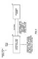
- FIG. 1is a block diagram of a tunable optical device that is the subject matter of the present invention.
- FIG. 2is a diagram of one embodiment of the tunable optical device shown in FIG. 1 .
- FIG. 3is a diagram of a tube-in-tube capacitive sensor arrangement that may be part of the embodiment of the tunable optical device shown in FIG. 1 .
- FIG. 4a diagram of a single tube capacitive sensor arrangement that may be part of the embodiment of the tunable optical deice shown in FIG. 1 .
- FIG. 5is a diagram of a multiple tube-in-tube capacitive sensor arrangement that may be part of the embodiment of the tunable optical device shown in FIG. 1 .
- FIG. 6is a diagram of a tube-in-tube capacitive differential sensor arrangement that may be part of embodiment of the tunable optical device shown in FIG. 1 .
- FIG. 7is a diagram of another sensor arrangement for the tunable optical device shown in FIG. 1 .
- FIG. 8is a diagram of another sensor arrangement for the tunable optical device shown in FIG. 1 .
- FIG. 9is a diagram of another sensor arrangement for the tunable optical device shown in FIG. 1 .
- FIG. 9Ais a diagram of another sensor arrangement for the tunable optical device shown in FIG. 9 .
- FIG. 10is a diagram of one sensor arrangement for the tunable optical device shown in FIG. 1 .
- FIG. 11is a diagram of another sensor arrangement for the tunable optical device shown in FIG. 1 .
- FIG. 12is a diagram of another sensor arrangement for the tunable optical device shown in FIG. 1 .
- FIG. 13is a diagram of another sensor arrangement for the tunable optical device shown in FIG. 1 .
- FIG. 14is a diagram of another sensor arrangement for the tunable optical device shown in FIG. 1 .
- FIG. 15is a diagram of another sensor arrangement for the tunable optical device shown in FIG. 1 .
- FIG. 16Aa diagram of a first plate for sensor arrangements for the tunable optical device shown in FIG. 2 .
- FIG. 16Bis a diagram of a second plate for sensor arrangements for the tunable optical device shown in FIG. 2 .
- FIG. 1The Basic Invention
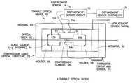
- FIG. 1shows a tunable optical device generally indicated as 20 having a compression tuned optical structure 22 and a displacement sensor 24 .
- the compression tuned optical structure 22responds to an optical signal, and further responds to a displacement sensor signal, for providing a compression tuned optical structure signal containing information about a change in an optical characteristic of the compression tuned optical structure, and for also further providing an excitation caused by a change in a displacement of the compression tuned optical structure 22 .
- the displacement sensor 24responds to the excitation from the compression tuned optical structure 22 , for providing the displacement sensor signal containing information about the change in the displacement of the compression tuned optical structure.
- the compression tuned optical structure 22is in the form of a dogbone-shaped structure (hereinafter “dogbone structure”), which is an all-glass compression unit that may be formed by glass collapsing technology shown and described in U.S. patent application Ser. No. 09/455,867 (CiDRA File No. CC 0036B), filed Dec. 6, 1999, as well as U.S. patent application Ser. No. 09/455,865 (CiDRA File No. CC-0078B), filed Dec. 6, 1999, both hereby incorporated by reference in their entirety, as discussed below in more detail.
- the compression tuned optical structure 22can also be in the form of a single large diameter waveguide known as a fiber cane, shown and described in U.S. patent application Ser. No.
- the compression tuned optical structure 22may also include Bragg grating, fiber Bragg grating or Fabry-Perot interferometer based optical structures, as discussed herein.
- the present inventionis shown and described below in relation to many different embodiments of the compression tuned optical structure 22 and the overall dogbone structure.
- the displacement sensor 24may include either capacitive or inductive sensing to measure displacement. Capacitive sensing is shown and described in terms of plates affixed to the compression tuned optical structure 22 separated by a given gap or distance, while inductive sensing is understood to be coils (instead of plates) separated by a given gap or distance.
- the scope of the inventionis not intended to be limited to any particular application of the tunable optical device 20 .
- the tunable optical device 20is used as an optical sensing device (such as a pressure sensor), as well as an optical signal-generating device (such as laser devices).
- FIG. 2The Tunable Optical Device 22
- FIG. 2shows a tunable optical device generally indicated as 50 , having the compression tuned optical structure 22 (see also FIG. 1) and the displacement sensor 24 (see also FIG. 1 ).
- the compression tuned optical structure 22includes a glass element 54 having a compression element 56 arranged therein, a pair of holders 58 coupled to the glass element 54 and arranged inside a housing 60 , and an actuator 62 arranged between one holder 58 and a wall of the housing 60 .
- the actuator 62may be any type of device that provides a compressive force, including a piezoelectric (PZT) device, a stepper motor, a magnetostrictive device, or any type of pressure-inducing device.
- the glass element 54has two wide end portions 54 a , 54 b and a narrow intermediate portion 54 c.
- the displacement sensor 24includes a displacement sensor circuit 70 , a displacement sensor controller 71 and capacitive elements 72 , 74 connected to the glass element 54 as well as the actuator 62 .
- the capacitive elements 72 , 74are affixed to the wide end portions 54 a , 54 b of the glass element 54 , and move in relation to one another when the wide end portions 54 a , 54 b are displaced by a compressive force or pressure.
- the glass element 54responds to an optical signal along the optical fiber 52
- the actuator 62responds to a displacement sensor signal from the displacement sensor controller 71 , for providing a compression tuned optical structure signal along the optical fiber 52 containing information about a change in an optical characteristic of the compression element 56 in the glass element 54 , and for also further providing an excitation caused by a change in a displacement of the wide end portions 54 a , 54 b of the glass element 54 of the compression tuned optical structure 22 .
- the excitationoccurs when the actuator 62 compresses the glass element 54 .
- the capacitive elements 72 , 74 of the displacement sensor 24respond to the excitation (i.e. the movement), which is sensed by the displacement circuit 70 and processed by the displacement sensor controller 71 , for providing the displacement sensor signal containing information about the change in the displacement of the wide end portions 54 a , 54 b of the glass element 54 of the compression tuned optical structure 22 .
- the capacitive elements 72 , 74are described as a part of the displacement sensor 24 (see also FIG. 1 ).
- the spirit of inventionincludes an understanding that the capacitive elements 72 , 74 could be described as a part of the compression tuned optical structure 22 (see also FIG. 1 ), as well.
- the compression tuned optical structure 22would provide some excitation signal to the displacement sensor 24 .
- the excitation signalcan be in the form of a capacitance, inductive, optical, microwave or time-of-flight signal.
- the scope of the inventionis not intended to be limited to any particular type of displacement sensing.
- the displacement sensor circuit 70 and the displacement sensor controllermay be used to calibrate the operation of the actuator 62 . It has been found that the displacement of the glass element 54 may change due to wear and tear over time, changing due to the effects of being maintained under compression and actuated periodically by a compressive force. The displacement sensor circuit 70 and the displacement sensor controller 71 will take changes in displacement into account so that signal for actuating the actuator 62 is modified consistent with the change in the displacement. A person skilled in the art would appreciate, without undue experimentation, how to implement the displacement sensor circuit 70 and the displacement sensor controller 71 after reading the specification in conjunction with that shown in the drawing.
- the calibration associated with the change of displacementcan be perform by the displacement sensor circuit 70 , the displacement sensor controller 71 , or a controller or some other circuit in the actuator 62 .
- FIG. 2also shows a thermistor circuit and sensor 76 for sensing the ambient temperature of the glass element 54 in the proximity of the compressive element 56 .
- the thermistor circuit and sensor 76is shown and described in relation to an optical structure in U.S. patent application Ser. No. 09/448,367 (CiDRA File No. CC 0218 and WFVA File no. 712-2-76), filed Nov. 23, 1999, hereby incorporated by reference in its entirety.
- the “dogbone” structure 104is an all-glass fiber Bragg grating compression unit having the fiber Bragg grating (FBG) 114 , as shown, or in the form of a distributed feedback (DFB) laser.
- the dogbone structure 104may be in the form of a glass tube having the optical fiber 102 fused therein.
- the narrower intermediate portion 104 chas the fiber Bragg grating 114 arranged therein with gratings spaced along the axis of compression.
- the wider end portions 104 a , 104 bhave a larger cross-section than the narrower intermediate portion 104 c .
- the dogbone structure 104provides for amplification of the compression force applied on one or more of the wider end portions 104 a , 104 b as applied to the fiber Bragg gratings spaced in the narrower intermediate portion 22 c .
- the amplification by the “dogbone” structure 104is analogous to Pascal's Principle in fluid dynamics, where an external pressure applied to a fluid confined within a closed container is transmitted undiminished throughout the entire fluid, so pressure is applied as a function of force per unit area in the “dogbone” structure 104 .
- the dogbone structure 104can be formed by taking the optical fiber and inserting it into an alignment tube of an inner diameter just larger than that of the outer diameter of the fibers, which is then collapsed on the optical fiber.
- such glass collapsing technologyis shown and described in U.S. patent application Ser. No. 09/455,867 (CiDRA File No. CC 0036B), as well as U.S. patent application Ser. No. 09/455,865 (CiDRA File No. CC 0078B), discussed above.
- this glass collapsing technologyrelates to collapsing a 1 millimeter tube of the optical fiber, then collapsing a 3 millimeter tube onto the 1 millimeter tube.
- the resulting all-glass tubemay be ground to form the “dogbone” shape structure 104 .
- the inventionis described in relation to a “dogbone” shaped compression unit; however, the scope of the invention is intended to cover shapes other than a “dogbone” structure, such as a straight tubular cylindrical structure.
- the dogbone structure 104also can be in the form of a single large diameter waveguide having a core with the gratings spaced therein, also known as a fiber cane, shown and described in United States patent application Ser. No. 09/455,868 (CiDRA File No. CC 0230), as well as U.S. patent application Ser. No. 09/456,112 (CiDRA File No. CC 0129B), discussed above.
- FIG. 3Tube-in-tube Capacitance Sensor Arrangement
- FIG. 3shows a tube-in-tube capacitance sensor arrangement generally indicated as 100 that may be used in the tunable optical device shown in FIG. 2 .
- the tube-in-tube capacitance sensor arrangement 100is shown in relation to an optical fiber 102 coupled to a compression tuned glass element 104 .
- the tunable optical device 100has a “tube-in-tube” design which can be used to measure a displacement of the compression tuned glass element 104 using a capacitive sensor where the effective area changes with displacement.
- the compression tuned glass element 104has the “dogbone” structure having two wider end portions 104 a , 104 b separated a narrower intermediate portion 104 c .
- One wider end portion 104 ahas an inner tube 106 having an inner capacitive plate 108
- another wider end portion 104 bhas an outer tube 110 having an outer capacitive plate 112 .
- the narrower intermediate portion 104 chas a compression element 114 in the form of a fiber Bragg grating.
- the compression element 114may also be in the form of a Fabry-Perot interferometer having two Bragg gratings separated by a predetermined distance.
- the capacitive plates 108 , 112have a metallic coating, such as gold.
- the change in the displacement of the glass element 104causes a change in the gap between the two capacitive plates 108 , 112 , and the change in capacitance depends on the change in the overlapping area.
- the two gold-coated tubes 106 , 110are affixed over the glass element 104 such that the gold surfaces face each other with a small gap (about 200 micron) between them.
- the tubes 106 , 110would be welded to the large diameter section of the dogbone element.
- Electrodeswould be attached to the gold-coated tubes to allow connection of the capacitor to an electronic device (not shown) capable of measuring capacitance. As the dogbone element is strained, the gap between the parallel plates will change, thereby causing the capacitance to change.
- a measurement of the capacitancewill be directly related to the Bragg wavelength, provided the temperature of the element is either held constant or measured. Since the tubes are directly connected to the glass element 104 , they are completely passive and will not slip. A person skilled in the art would be able to implement without undue experimentation the electronics circuit (not shown) to measure the change in capacitance between the two capacitive plates 108 , 112 .
- FIG. 4Single Tube Capacitance Sensor Arrangement
- FIG. 4shows a single tube capacitance sensor arrangement generally indicated as 200 that may be used in the tunable optical device 100 shown in FIG. 2 .
- the single tube-in-tube capacitance sensor arrangement 200is shown in relation to an optical fiber 202 coupled to a compression tuned glass element 204 .
- Similar elements in FIGS. 2-4are labelled with similar reference numerals with the addition of 100 .
- FIG. 3The design in FIG. 3 above is simplified as shown in FIG. 4 by elimination of the one tube 110 and extending the remaining tube 206 over the larger diameter of the compression tuned glass element 204 .
- the compression tuned glass element 204has two wider end portion 204 a , 204 b separated by a narrower intermediate portion 204 c .
- One wider end portion 204 ahas an inner tube 206 having an inner capacitive plate 208
- another wider end portion 204 bhas an outer surface with an outer capacitive plate 212 .
- the single tube capacitance sensor arrangement 200greatly eases manufacturing and can eliminate alignment issues with other designs.
- One complication with the delta area based capacitive sensorcould be the limited area change of the sensor and, therefore, a restriction of the resolution of the measurement.
- FIG. 5Multiple Tube-in-Tube
- FIG. 5shows a multiple tube-in-tube capacitance sensor arrangement generally indicated as 300 that may be used in the tunable optical device 100 shown in FIG. 2 .
- the multiple tube-in-tube capacitance sensor arrangement 300is shown in relation to an optical fiber 302 coupled to a compression tuned glass element 304 . Similar elements in FIGS. 3-5 are labelled with similar reference numerals with the addition of 100 .
- the tunable optical device 300has multiple tubes that could be interleaved to increase the effective area change as the compression element is compressed.
- the compression tuned glass element 304has two wider end portions 304 a , 304 b separated a narrower intermediate portion 304 c .
- One wider end portion 304 ahas tubes 306 a , 306 b having capacitive plates 308 a , 308 b , 308 c
- another wider end portion 104 bhas tubes 310 a , 310 b with capacitive plates 312 a , 312 b , 312 c.
- FIG. 6Tube-in-Tube Capacitance
- FIG. 6shows a tube-in-tube capacitance differential sensor arrangement generally indicated as 400 that may be used in the tunable optical device 100 shown in FIG. 2 .
- the tube-in-tube capacitance differential sensor arrangement 400is shown in relation to an optical fiber 402 coupled to a compression tuned glass element 404 .
- Similar elements in FIGS. 3-6are labelled with similar reference numerals with the addition of 100 .
- the tube-in-tube capacitance differential sensor arrangement 400is formed as a differential sensor, so one capacitive section would decrease in value while another capacitive section increases providing a differential measurement which can provide increased resolution.
- the compression tuned glass element 404has two wider end portions 404 a , 404 b separated a narrower intermediate portion 404 c .
- One wider end portion 404 ahas an inner tube 406 having capacitive plates 408 a , 408 b
- another wider end portion 404 bhas an outer tube 412 with capacitive plates 412 a , 412 b .
- one capacitance valuewill decrease with compression, while the other capacitance value will increase with pressure.
- the capacitance between plates 408 a , 412 adecreases (less overlapping plate area), while the capacitance between plates 408 b , 412 b increases (more overlapping plate area), and vice versa, when the compression force is relaxed.
- a person skilled in the artwould be able to implement without undue experimentation a differential electronics circuit (not shown) to measure the change in capacitance between the capacitive plates 408 a , 412 a , or 408 b , 412 b.
- FIG. 7shows a part of a tunable optical device generally indicated 500 having a capacitance sensor arrangement with capacitive elements 502 , 504 , which may be plates or rods, as shown. Similar elements in FIGS. 2 and 7 are labelled with similar reference numerals.
- the displacement sensor 24(FIG. 1) or the displacement circuit 70 (FIG. 2) is not shown but would be connected to the capacitive elements 502 , 504 .
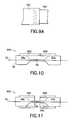
- FIG. 8shows a capacitance sensor arrangement generally indicated 600 having capacitive elements 602 , 604 , which may be L-shaped plates or rods, as shown. Similar elements in FIGS. 2 and 7 - 8 are labelled with similar reference numerals.
- the displacement sensor 24 (FIG. 1) or the displacement circuit 70 (FIG. 2)is not shown but would be connected to the L-shaped capacitive elements 602 , 604 .
- FIGS. 9 and 9Aare identical to FIGS. 9 and 9A.
- FIG. 9shows a capacitance sensor arrangement generally indicated as 700 with overlapping capacitive elements 702 , 704 , which may be rods and plates, as shown. Similar elements in FIGS. 2 and 7 - 9 are labelled with similar reference numerals.
- FIG. 9Ashows an alternative embodiment wherein one of the overlapping capacitive elements 704 ′ has a sawtooth shape.
- the displacement sensor 24 (FIG. 1) or the displacement circuit 70 (FIG. 2)is not shown but would be connected to the capacitive elements 702 , 704 .
- FIG. 10shows a capacitance sensor arrangement generally indicated as 800 with overlapping capacitive elements 802 , 804 , which may be plates or rods having corresponding angled capacitive surfaces, as shown. Similar elements in FIGS. 2 and 7 - 10 are labelled with similar reference numerals.
- the displacement sensor 24(FIG. 1) or the displacement circuit 70 (FIG. 2) is not shown but would be connected to the capacitive elements 802 , 804 .
- FIG. 11shows a capacitance sensor arrangement generally indicated as 900 with capacitive elements 902 , 904 , which may be tubes having corresponding surfaces, as shown. Similar elements in FIGS. 2 and 7 - 11 are labelled with similar reference numerals.
- the displacement sensor 24(FIG. 1) or the displacement circuit 70 (FIG. 2) is not shown but would be connected to the capacitive elements 902 , 904 .
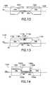
- FIG. 12shows a capacitance sensor arrangement generally indicated as 1000 with capacitive elements 1002 , 1004 , which may be tubes having corresponding wires 1006 , 1008 connected to capacitive surfaces, as shown. Similar elements in FIGS. 2 and 7 - 12 are labelled with similar reference numerals.
- the displacement sensor 24 (FIG. 1) or the displacement circuit 70 (FIG. 2)is not shown but would be connected to the capacitive elements 1002 , 1004 .
- FIG. 13shows a differential capacitance sensor arrangement generally indicated as 1100 with capacitive elements 1102 , 1104 , which may be overlapping rods, tubes or plates, as shown.
- the differential capacitance sensor 1100may also include a reference capacitor 1108 and a variable capacitor 1110 .
- the reference capacitor 1108does not vary and allows a compensation for temperature, while the variable capacitor 1110 does vary in relation to the values of the two different capacitors generally indicated as 1110 a , 1110 b .
- Similar elements in FIGS. 2 and 7 - 13are labelled with similar reference numerals.
- the displacement sensor 24 (FIG. 1) or the displacement circuit 70 (FIG. 2)is not shown but would be connected to the reference capacitor 1108 and the variable capacitor 1110 .
- FIG. 14shows a differential capacitance sensor arrangement generally indicated as 1200 with a capacitive element 1202 , which includes two variable differential capacitors 1204 , 1206 , as shown.
- One variable differential capacitor 1204has plates 1204 a , 1204 b respectively affixed on a surface of one wide portion 54 a of the glass element 54 and on the surface of the capacitive element 1202 .
- the other variable differential capacitor 1206has plates 1206 a , 1206 b respectively affixed on a surface of the other wide portion 54 b of the glass element 54 and on the surface of the capacitive element 1202 .
- Similar elements in FIGS. 2 and 7 - 13are labelled with similar reference numerals.
- the displacement sensor 24 (FIG. 1) or the displacement circuit 70 (FIG. 2)is not shown but would be connected to the differential capacitors 1204 , 1206 .
- FIG. 15shows a differential capacitance sensor arrangement generally indicated as 1300 with capacitive elements 1302 , 1304 , which may be overlapping rods, tubes or plates, as shown.
- the differential capacitance sensor 1100includes a reference capacitor 1306 and a variable capacitor 1310 having a plate 1 and a plate 2 , as shown. Similar elements in FIGS. 2 and 7 - 15 are labelled with similar reference numerals.
- the displacement sensor 24 (FIG. 1) or the displacement circuit 70 (FIG. 2)is not shown but would be connected to the reference capacitor 1306 and the variable capacitor 1308 .
- FIGS. 16A, 16 Bare identical to FIGS. 16A, 16 B.
- FIG. 16Ashows an example of a first capacitive plate generally indicated as 1400 that can be used with one or more of the capacitive plates shown in FIGS. 1-15.
- the first capacitive platewill cooperate with a second capacitive plate 1500 shown in FIG. 16B to reduce noise and voltage from electromagnetic interference (EMI) between the two ground of the capacitive plates.
- EMIelectromagnetic interference
- the first capacitive plate 1400includes an outer ring 1402 , an intermediate ring 1404 and an inner ring 1406 .
- the intermediate ring 1404is connected via a line 1404 a to a voltage source (not shown) and the outer ring 1402 and the inner ring 1406 are connected via a line 1406 a to a ground source (not shown).
- the second capacitive plate 1500includes an outer ring 1502 and an intermediate ring 1504 .
- the intermediate ring 1504is connected via a line 1504 a to a voltage source (not shown) and the outer ring 1402 is connected via a line 1406 a to a ground source (not shown).
- the voltage line 1404 a and 1504 a , and the ground lines 1406 a and 1502 amay be connected via lines 72 a , 74 a shown in FIG. 2 to the displacement sensor circuit 70 .
- the combined capacitive plates 1400 , 1500reduce edge affects and act as a shield with respect to coupling of stray interference.
- the inventionhas been described with respect to using a capacitor to measure the gap distance, it should be understood by those skilled in the art that other gap sensing techniques may be used, such an inductive, optical, magnetic, microwave, time-of-flight based gap sensors. Moreover, the scope of the invention is also intended to include measuring or sensing a force applied on or about the compressive element, and feeding it back to control the compression tuning of the optical structure.
Landscapes
- Physics & Mathematics (AREA)
- General Physics & Mathematics (AREA)
- Optics & Photonics (AREA)
- Nonlinear Science (AREA)
- Length Measuring Devices By Optical Means (AREA)
- Optical Transform (AREA)
- Mechanical Light Control Or Optical Switches (AREA)
Abstract
Description
Claims (22)
Priority Applications (11)
| Application Number | Priority Date | Filing Date | Title |
|---|---|---|---|
| US09/519,802US6310990B1 (en) | 2000-03-16 | 2000-03-16 | Tunable optical structure featuring feedback control |
| AU4911101AAU4911101A (en) | 2000-03-16 | 2001-03-06 | Tunable optical structure featuring feedback control |
| JP2001565970AJP2003526124A (en) | 2000-03-06 | 2001-03-06 | Tunable optical structure featuring feedback control |
| CA002402287ACA2402287A1 (en) | 2000-03-06 | 2001-03-06 | Tunable optical structure featuring feedback control |
| KR1020027011683AKR20020088078A (en) | 2000-03-06 | 2001-03-06 | Tunable optical structure featuring feedback control |
| PCT/US2001/007369WO2001067045A2 (en) | 2000-03-06 | 2001-03-06 | Tunable optical structure featuring feedback control |
| CN01808884ACN1427947A (en) | 2000-03-06 | 2001-03-06 | Tunable optical structure featuring feedback control |
| AU2001249111AAU2001249111B2 (en) | 2000-03-06 | 2001-03-06 | Tunable optical structure featuring feedback control |
| EP01922294AEP1269122A2 (en) | 2000-03-06 | 2001-03-06 | Tunable optical structure featuring feedback control |
| US09/950,509US6563968B2 (en) | 2000-03-16 | 2001-09-10 | Tunable optical structure featuring feedback control |
| US10/226,944US6792009B2 (en) | 1998-12-04 | 2002-08-22 | Tunable grating-based channel filter parking device |
Applications Claiming Priority (1)
| Application Number | Priority Date | Filing Date | Title |
|---|---|---|---|
| US09/519,802US6310990B1 (en) | 2000-03-16 | 2000-03-16 | Tunable optical structure featuring feedback control |
Related Child Applications (1)
| Application Number | Title | Priority Date | Filing Date |
|---|---|---|---|
| US09/950,509Continuation-In-PartUS6563968B2 (en) | 1998-12-04 | 2001-09-10 | Tunable optical structure featuring feedback control |
Publications (1)
| Publication Number | Publication Date |
|---|---|
| US6310990B1true US6310990B1 (en) | 2001-10-30 |
Family
ID=24069830
Family Applications (2)
| Application Number | Title | Priority Date | Filing Date |
|---|---|---|---|
| US09/519,802Expired - LifetimeUS6310990B1 (en) | 1998-12-04 | 2000-03-16 | Tunable optical structure featuring feedback control |
| US09/950,509Expired - LifetimeUS6563968B2 (en) | 1998-12-04 | 2001-09-10 | Tunable optical structure featuring feedback control |
Family Applications After (1)
| Application Number | Title | Priority Date | Filing Date |
|---|---|---|---|
| US09/950,509Expired - LifetimeUS6563968B2 (en) | 1998-12-04 | 2001-09-10 | Tunable optical structure featuring feedback control |
Country Status (8)
| Country | Link |
|---|---|
| US (2) | US6310990B1 (en) |
| EP (1) | EP1269122A2 (en) |
| JP (1) | JP2003526124A (en) |
| KR (1) | KR20020088078A (en) |
| CN (1) | CN1427947A (en) |
| AU (2) | AU4911101A (en) |
| CA (1) | CA2402287A1 (en) |
| WO (1) | WO2001067045A2 (en) |
Cited By (28)
| Publication number | Priority date | Publication date | Assignee | Title |
|---|---|---|---|---|
| US20020196995A1 (en)* | 2001-06-18 | 2002-12-26 | Weatherford/Lamb, Inc. | Fabry-Perot sensing element based on a large-diameter optical waveguide |
| US6563968B2 (en)* | 2000-03-16 | 2003-05-13 | Cidra Corporation | Tunable optical structure featuring feedback control |
| US6594410B2 (en)* | 2000-08-26 | 2003-07-15 | Cidra Corporation | Wide range tunable optical filter |
| US6594288B1 (en)* | 2000-11-06 | 2003-07-15 | Cidra Corporation | Tunable raman laser and amplifier |
| US20030231844A1 (en)* | 2001-06-18 | 2003-12-18 | Kersey Alan D. | Fabry-Perot filter/resonator |
| US6915686B2 (en) | 2003-02-11 | 2005-07-12 | Optoplan A.S. | Downhole sub for instrumentation |
| US20050160947A1 (en)* | 2002-08-30 | 2005-07-28 | Halliburton Energy Services, Inc. | Process for controlling gas migration during well cementing |
| US7159653B2 (en) | 2003-02-27 | 2007-01-09 | Weatherford/Lamb, Inc. | Spacer sub |
| US20070103697A1 (en)* | 2005-06-17 | 2007-05-10 | Degertekin Fahrettin L | Integrated displacement sensors for probe microscopy and force spectroscopy |
| US20070295064A1 (en)* | 2005-10-07 | 2007-12-27 | Degertekin Fahrettin L | Methods of imaging in probe microscopy |
| US7386204B1 (en)* | 2000-08-26 | 2008-06-10 | Cidra Corporation | Optical filter having a shaped filter function |
| US20080168830A1 (en)* | 2005-10-28 | 2008-07-17 | Georgia Tech Research Corporation | Devices for Probe Microscopy |
| US20080209988A1 (en)* | 2006-08-15 | 2008-09-04 | Georgia Tech Research Corporation | Cantilevers with integrated actuators for probe microscopy |
| US20080229847A1 (en)* | 2007-03-20 | 2008-09-25 | Divyasimha Harish | Capacitive sensor based structure and method with tilt compensation capability |
| WO2006138697A3 (en)* | 2005-06-17 | 2009-04-16 | Georgia Tech Res Inst | Integrated displacement sensors for probe microscopy and force spectroscopy |
| US20090177095A1 (en)* | 2006-06-09 | 2009-07-09 | Nicolas Aeby | Triaxial fiber optic force sensing catheter |
| US20110087112A1 (en)* | 2005-08-01 | 2011-04-14 | Giovanni Leo | Medical apparatus system having optical fiber load sensing |
| US8048063B2 (en) | 2006-06-09 | 2011-11-01 | Endosense Sa | Catheter having tri-axial force sensor |
| US8075498B2 (en) | 2005-03-04 | 2011-12-13 | Endosense Sa | Medical apparatus system having optical fiber load sensing capability |
| US8157789B2 (en) | 2007-05-24 | 2012-04-17 | Endosense Sa | Touch sensing catheter |
| US8182433B2 (en) | 2005-03-04 | 2012-05-22 | Endosense Sa | Medical apparatus system having optical fiber load sensing capability |
| US8298227B2 (en) | 2008-05-14 | 2012-10-30 | Endosense Sa | Temperature compensated strain sensing catheter |
| US20130204142A1 (en)* | 2012-02-07 | 2013-08-08 | Sensoptic Sa | Optical force sensing element and microsurgical instrument |
| US8622935B1 (en) | 2007-05-25 | 2014-01-07 | Endosense Sa | Elongated surgical manipulator with body position and distal force sensing |
| US10561368B2 (en) | 2011-04-14 | 2020-02-18 | St. Jude Medical International Holding S.À R.L. | Compact force sensor for catheters |
| US10584959B2 (en)* | 2016-11-30 | 2020-03-10 | Hottinger Baldwin Messtechnik Gmbh | Weldable FBG strain sensor arrangement |
| US10698174B2 (en) | 2017-04-17 | 2020-06-30 | Samsung Electro-Mechanics Co., Ltd. | Camera module and sensing unit to detect a detection target |
| US11445937B2 (en) | 2016-01-07 | 2022-09-20 | St. Jude Medical International Holding S.À R.L. | Medical device with multi-core fiber for optical sensing |
Families Citing this family (31)
| Publication number | Priority date | Publication date | Assignee | Title |
|---|---|---|---|---|
| US20040037501A1 (en)* | 2000-11-16 | 2004-02-26 | Stepanov Dimitrii Yu | Operational tuning of optical structures |
| US6831450B2 (en)* | 2001-10-19 | 2004-12-14 | Nortel Networks, Ltd. | Electronic method and apparatus for measuring optical wavelength and locking to a set optical wavelength of Fabry-Perot tunable cavity opto-electronic devices |
| US7110624B2 (en)* | 2001-12-14 | 2006-09-19 | Evans & Sutherland Computer Corporation | Fiber optic mechanical/thermal tuner and isolator |
| US6618544B1 (en)* | 2002-02-12 | 2003-09-09 | Lawrence E. Bodkin, Sr. | Fiberoptics protective emission control |
| US7060964B1 (en)* | 2002-11-12 | 2006-06-13 | Ifos, Inc. | Reflection-mode fiber sensing devices |
| US6768750B2 (en)* | 2002-11-12 | 2004-07-27 | Corning Incorporated | Multi-spectral line Raman laser |
| US7027699B2 (en)* | 2003-05-21 | 2006-04-11 | The Hong Kong Polytechnic University | Optical fiber and optical fiber sensors |
| US20050236559A1 (en)* | 2004-03-12 | 2005-10-27 | Calvert Sean G | Fiber grating strain sensors for civil structures |
| US7305158B2 (en)* | 2004-04-15 | 2007-12-04 | Davidson Instruments Inc. | Interferometric signal conditioner for measurement of absolute static displacements and dynamic displacements of a Fabry-Perot interferometer |
| EP1586854A3 (en)* | 2004-04-15 | 2006-02-08 | Davidson Instruments | Interferometric signal conditioner for measurement of the absolute length of gaps in a fiber optic Fabry-Pérot interferometer |
| US7492463B2 (en) | 2004-04-15 | 2009-02-17 | Davidson Instruments Inc. | Method and apparatus for continuous readout of Fabry-Perot fiber optic sensor |
| EP1869737B1 (en) | 2005-03-16 | 2021-05-12 | Davidson Instruments, Inc. | High intensity fabry-perot sensor |
| CA2541028A1 (en)* | 2005-03-24 | 2006-09-24 | Opsens Inc. | Adhesive-assembled fiber-optic interferometer |
| BRPI0501790B1 (en)* | 2005-05-17 | 2019-02-12 | Petroleo Brasileiro S.A. - Petrobras | SYSTEMS WITH REMOTE FIBER OPTICAL POSITION TRANSDUCER AND POSITION CALIBRATION METHOD |
| WO2007033069A2 (en) | 2005-09-13 | 2007-03-22 | Davidson Instruments Inc. | Tracking algorithm for linear array signal processor for fabry-perot cross-correlation pattern and method of using same |
| EP2021747B1 (en)* | 2006-04-26 | 2018-08-01 | Halliburton Energy Services, Inc. | Fiber optic mems seismic sensor with mass supported by hinged beams |
| US8115937B2 (en)* | 2006-08-16 | 2012-02-14 | Davidson Instruments | Methods and apparatus for measuring multiple Fabry-Perot gaps |
| JP2008060445A (en)* | 2006-09-01 | 2008-03-13 | Nec Corp | Light emitting element |
| EP2104930A2 (en) | 2006-12-12 | 2009-09-30 | Evans & Sutherland Computer Corporation | System and method for aligning rgb light in a single modulator projector |
| DE102008020247B4 (en)* | 2008-04-22 | 2012-08-02 | Eads Deutschland Gmbh | Measuring arrangement with a fiber Bragg grating for detecting strains and / or temperatures |
| US8358317B2 (en) | 2008-05-23 | 2013-01-22 | Evans & Sutherland Computer Corporation | System and method for displaying a planar image on a curved surface |
| US8702248B1 (en) | 2008-06-11 | 2014-04-22 | Evans & Sutherland Computer Corporation | Projection method for reducing interpixel gaps on a viewing surface |
| US8077378B1 (en) | 2008-11-12 | 2011-12-13 | Evans & Sutherland Computer Corporation | Calibration system and method for light modulation device |
| KR101007948B1 (en)* | 2010-08-13 | 2011-01-14 | 김지훈 | Molding method of rubber block using steam |
| JP5720200B2 (en)* | 2010-11-25 | 2015-05-20 | セイコーエプソン株式会社 | Optical module and optical measuring device |
| US9641826B1 (en) | 2011-10-06 | 2017-05-02 | Evans & Sutherland Computer Corporation | System and method for displaying distant 3-D stereo on a dome surface |
| DE102013205205A1 (en)* | 2013-03-25 | 2014-10-09 | Fraunhofer-Gesellschaft zur Förderung der angewandten Forschung e.V. | Fiber optic sensor and its use |
| US20160161326A1 (en)* | 2013-12-01 | 2016-06-09 | Mao-Jen Wu | Flexible Optical Sensor Module |
| DE102015015337B4 (en)* | 2015-09-01 | 2018-06-21 | Abp Induction Systems Gmbh | Induction crucible furnace and magnetic conclusion for this |
| CN108322085B (en)* | 2018-02-28 | 2024-08-16 | 复拓科学仪器(苏州)有限公司 | Piezoelectric ceramic nano resolution displacement driver |
| NO20201324A1 (en)* | 2018-05-24 | 2020-12-02 | Baker Hughes Holdings Llc | Transducers including laser etched substrates |
Citations (49)
| Publication number | Priority date | Publication date | Assignee | Title |
|---|---|---|---|---|
| US5026137A (en) | 1988-09-26 | 1991-06-25 | Canon Kabushiki Kaisha | Light signal transmission system |
| US5042898A (en) | 1989-12-26 | 1991-08-27 | United Technologies Corporation | Incorporated Bragg filter temperature compensated optical waveguide device |
| US5107360A (en) | 1990-11-05 | 1992-04-21 | General Instrument Corporation | Optical transmission of RF subcarriers in adjacent signal bands |
| US5115338A (en) | 1990-05-30 | 1992-05-19 | At&T Bell Laboratories | Multi-stage optical amplifier |
| US5119447A (en) | 1990-11-06 | 1992-06-02 | General Instrument Corporation | Apparatus and method for externally modulating an optical carrier |
| US5134620A (en) | 1990-11-20 | 1992-07-28 | General Instrument Corporation | Laser with longitudinal mode selection |
| US5140456A (en) | 1991-04-08 | 1992-08-18 | General Instrument Corporation | Low noise high power optical fiber amplifier |
| US5151908A (en) | 1990-11-20 | 1992-09-29 | General Instrument Corporation | Laser with longitudinal mode selection |
| US5153762A (en) | 1990-03-19 | 1992-10-06 | General Instrument Corporation | Method and apparatus for recovering AM channell signals distributed on an optical fiber |
| US5166821A (en) | 1991-03-12 | 1992-11-24 | General Instrument Corporation | Reduction of non-linear effects in optical fiber communication systems and method of using same |
| US5187760A (en) | 1992-01-23 | 1993-02-16 | General Instrument Corporation | Wavelength selective coupler for high power optical communications |
| US5191586A (en) | 1991-07-18 | 1993-03-02 | General Instrument Corporation | Narrow band incoherent optical carrier generator |
| US5200964A (en) | 1991-03-12 | 1993-04-06 | General Instrument Corporation | Broad linewidth lasers for optical fiber communication systems |
| US5208819A (en) | 1992-01-23 | 1993-05-04 | General Instrument Corporation | Optical source with frequency locked to an in-fiber grating resonantor |
| US5210633A (en) | 1990-09-12 | 1993-05-11 | General Instrument Corporation | Apparatus and method for linearizing the operation of an external optical modulator |
| US5210631A (en) | 1989-12-22 | 1993-05-11 | General Instrument Corporation | Transmission of AM-VSB video signals over an optical fiber |
| US5222089A (en) | 1992-01-08 | 1993-06-22 | General Instrument Corporation | Optical signal source for overcoming distortion generated by an optical amplifier |
| US5231529A (en) | 1990-12-19 | 1993-07-27 | Nec Corporation | Light amplifier for multi-wavelength signals |
| US5243609A (en) | 1990-11-20 | 1993-09-07 | General Instrument Corporation | Laser with longitudinal mode selection |
| US5245863A (en)* | 1990-07-11 | 1993-09-21 | Olympus Optical Co., Ltd. | Atomic probe microscope |
| US5257124A (en) | 1991-08-15 | 1993-10-26 | General Instrument Corporation | Low distortion laser system for AM fiber optic communication |
| US5257125A (en) | 1991-11-27 | 1993-10-26 | Xerox Corporation | Afocal optical system for focus error correction in laser scanning systems |
| US5260823A (en) | 1990-05-21 | 1993-11-09 | University Of Southampton | Erbium-doped fibre amplifier with shaped spectral gain |
| US5268910A (en) | 1991-07-18 | 1993-12-07 | General Instrument Corporation | Superluminescent optical source |
| US5271024A (en) | 1992-07-27 | 1993-12-14 | General Instrument Corporation | Optical fiber amplifier and laser with flattened gain slope |
| US5394741A (en)* | 1990-07-11 | 1995-03-07 | Olympus Optical Co., Ltd. | Atomic probe microscope |
| US5469520A (en) | 1994-09-30 | 1995-11-21 | United Technologies Corporation | Compression-tuned fiber grating |
| US5502781A (en) | 1995-01-25 | 1996-03-26 | At&T Corp. | Integrated optical devices utilizing magnetostrictively, electrostrictively or photostrictively induced stress |
| US5579143A (en) | 1993-06-04 | 1996-11-26 | Ciena Corporation | Optical system with tunable in-fiber gratings |
| US5608825A (en) | 1996-02-01 | 1997-03-04 | Jds Fitel Inc. | Multi-wavelength filtering device using optical fiber Bragg grating |
| US5691999A (en) | 1994-09-30 | 1997-11-25 | United Technologies Corporation | Compression-tuned fiber laser |
| US5706375A (en) | 1996-09-10 | 1998-01-06 | Jds Fitel Inc. | Variable-attenuation tunable optical router |
| US5726785A (en) | 1995-02-28 | 1998-03-10 | France Telecom | Optical add-drop multiplexer using optical circulators and photoinduced Bragg gratings |
| US5748349A (en) | 1996-03-27 | 1998-05-05 | Ciena Corp. | Gratings-based optical add-drop multiplexers for WDM optical communication system |
| US5859941A (en) | 1995-12-07 | 1999-01-12 | Kokusai Denshin Denwa Kabushiki Kaisha | Optical add/drop multiplexer device |
| US5867289A (en) | 1996-12-24 | 1999-02-02 | International Business Machines Corporation | Fault detection for all-optical add-drop multiplexer |
| US5889901A (en)* | 1997-06-06 | 1999-03-30 | University Technology Corporation | Strain measuring apparatus/method having a sensor and a reference optical fiber grating |
| US5896378A (en) | 1994-01-26 | 1999-04-20 | Gpt Limited | SDH Add/Drop Multiplexer |
| US5920413A (en) | 1996-04-05 | 1999-07-06 | Kokusai Denshin Denwa Kabushiki-Kaisha | Method and device for optical add/drop multiplexing using high speed polarization scrambler |
| US5926300A (en) | 1996-03-04 | 1999-07-20 | Kokusai Denshin Denwa Kabushiki Kaisha | Optical add-drop multiplexer |
| US5953141A (en) | 1996-10-03 | 1999-09-14 | International Business Machines Corporation | Dynamic optical add-drop multiplexers and wavelength-routing networks with improved survivability and minimized spectral filtering |
| US5960133A (en) | 1998-01-27 | 1999-09-28 | Tellium, Inc. | Wavelength-selective optical add/drop using tilting micro-mirrors |
| US5959749A (en) | 1998-05-20 | 1999-09-28 | Nortel Networks Corporation | Optical add/drop multiplexer/demultiplexer |
| US5982518A (en) | 1996-03-27 | 1999-11-09 | Ciena Corporation | Optical add-drop multiplexers compatible with very dense WDM optical communication systems |
| US5991076A (en) | 1997-07-18 | 1999-11-23 | Cheng; Yihao | Optical circulator |
| US5999290A (en) | 1997-10-27 | 1999-12-07 | Lucent Technologies Inc. | Optical add/drop multiplexer having complementary stages |
| US6002503A (en) | 1997-10-23 | 1999-12-14 | Ciena Corporation | Optical add/drop multiplexer |
| US6020986A (en) | 1997-11-21 | 2000-02-01 | Jds Uniphase Corporation | Programmable add-drop module for use in an optical circuit |
| US6087655A (en)* | 1998-05-19 | 2000-07-11 | Kobrin; Boris | Fiber grating encoders and methods for fabricating the same |
Family Cites Families (3)
| Publication number | Priority date | Publication date | Assignee | Title |
|---|---|---|---|---|
| US4387601A (en)* | 1980-07-01 | 1983-06-14 | Hokushin Electric Works, Ltd. | Capacitance type displacement conversion device |
| US6310990B1 (en)* | 2000-03-16 | 2001-10-30 | Cidra Corporation | Tunable optical structure featuring feedback control |
| US6411746B1 (en)* | 2000-01-18 | 2002-06-25 | Corning Incorporated | Thermally tunable optical devices |
- 2000
- 2000-03-16USUS09/519,802patent/US6310990B1/ennot_activeExpired - Lifetime
- 2001
- 2001-03-06EPEP01922294Apatent/EP1269122A2/ennot_activeWithdrawn
- 2001-03-06KRKR1020027011683Apatent/KR20020088078A/ennot_activeWithdrawn
- 2001-03-06CACA002402287Apatent/CA2402287A1/ennot_activeAbandoned
- 2001-03-06AUAU4911101Apatent/AU4911101A/enactivePending
- 2001-03-06JPJP2001565970Apatent/JP2003526124A/enactivePending
- 2001-03-06WOPCT/US2001/007369patent/WO2001067045A2/enactiveIP Right Grant
- 2001-03-06CNCN01808884Apatent/CN1427947A/enactivePending
- 2001-03-06AUAU2001249111Apatent/AU2001249111B2/ennot_activeExpired
- 2001-09-10USUS09/950,509patent/US6563968B2/ennot_activeExpired - Lifetime
Patent Citations (49)
| Publication number | Priority date | Publication date | Assignee | Title |
|---|---|---|---|---|
| US5026137A (en) | 1988-09-26 | 1991-06-25 | Canon Kabushiki Kaisha | Light signal transmission system |
| US5210631A (en) | 1989-12-22 | 1993-05-11 | General Instrument Corporation | Transmission of AM-VSB video signals over an optical fiber |
| US5042898A (en) | 1989-12-26 | 1991-08-27 | United Technologies Corporation | Incorporated Bragg filter temperature compensated optical waveguide device |
| US5153762A (en) | 1990-03-19 | 1992-10-06 | General Instrument Corporation | Method and apparatus for recovering AM channell signals distributed on an optical fiber |
| US5260823A (en) | 1990-05-21 | 1993-11-09 | University Of Southampton | Erbium-doped fibre amplifier with shaped spectral gain |
| US5115338A (en) | 1990-05-30 | 1992-05-19 | At&T Bell Laboratories | Multi-stage optical amplifier |
| US5245863A (en)* | 1990-07-11 | 1993-09-21 | Olympus Optical Co., Ltd. | Atomic probe microscope |
| US5394741A (en)* | 1990-07-11 | 1995-03-07 | Olympus Optical Co., Ltd. | Atomic probe microscope |
| US5210633A (en) | 1990-09-12 | 1993-05-11 | General Instrument Corporation | Apparatus and method for linearizing the operation of an external optical modulator |
| US5107360A (en) | 1990-11-05 | 1992-04-21 | General Instrument Corporation | Optical transmission of RF subcarriers in adjacent signal bands |
| US5119447A (en) | 1990-11-06 | 1992-06-02 | General Instrument Corporation | Apparatus and method for externally modulating an optical carrier |
| US5134620A (en) | 1990-11-20 | 1992-07-28 | General Instrument Corporation | Laser with longitudinal mode selection |
| US5151908A (en) | 1990-11-20 | 1992-09-29 | General Instrument Corporation | Laser with longitudinal mode selection |
| US5243609A (en) | 1990-11-20 | 1993-09-07 | General Instrument Corporation | Laser with longitudinal mode selection |
| US5231529A (en) | 1990-12-19 | 1993-07-27 | Nec Corporation | Light amplifier for multi-wavelength signals |
| US5200964A (en) | 1991-03-12 | 1993-04-06 | General Instrument Corporation | Broad linewidth lasers for optical fiber communication systems |
| US5166821A (en) | 1991-03-12 | 1992-11-24 | General Instrument Corporation | Reduction of non-linear effects in optical fiber communication systems and method of using same |
| US5140456A (en) | 1991-04-08 | 1992-08-18 | General Instrument Corporation | Low noise high power optical fiber amplifier |
| US5191586A (en) | 1991-07-18 | 1993-03-02 | General Instrument Corporation | Narrow band incoherent optical carrier generator |
| US5268910A (en) | 1991-07-18 | 1993-12-07 | General Instrument Corporation | Superluminescent optical source |
| US5257124A (en) | 1991-08-15 | 1993-10-26 | General Instrument Corporation | Low distortion laser system for AM fiber optic communication |
| US5257125A (en) | 1991-11-27 | 1993-10-26 | Xerox Corporation | Afocal optical system for focus error correction in laser scanning systems |
| US5222089A (en) | 1992-01-08 | 1993-06-22 | General Instrument Corporation | Optical signal source for overcoming distortion generated by an optical amplifier |
| US5208819A (en) | 1992-01-23 | 1993-05-04 | General Instrument Corporation | Optical source with frequency locked to an in-fiber grating resonantor |
| US5187760A (en) | 1992-01-23 | 1993-02-16 | General Instrument Corporation | Wavelength selective coupler for high power optical communications |
| US5271024A (en) | 1992-07-27 | 1993-12-14 | General Instrument Corporation | Optical fiber amplifier and laser with flattened gain slope |
| US5579143A (en) | 1993-06-04 | 1996-11-26 | Ciena Corporation | Optical system with tunable in-fiber gratings |
| US5896378A (en) | 1994-01-26 | 1999-04-20 | Gpt Limited | SDH Add/Drop Multiplexer |
| US5691999A (en) | 1994-09-30 | 1997-11-25 | United Technologies Corporation | Compression-tuned fiber laser |
| US5469520A (en) | 1994-09-30 | 1995-11-21 | United Technologies Corporation | Compression-tuned fiber grating |
| US5502781A (en) | 1995-01-25 | 1996-03-26 | At&T Corp. | Integrated optical devices utilizing magnetostrictively, electrostrictively or photostrictively induced stress |
| US5726785A (en) | 1995-02-28 | 1998-03-10 | France Telecom | Optical add-drop multiplexer using optical circulators and photoinduced Bragg gratings |
| US5859941A (en) | 1995-12-07 | 1999-01-12 | Kokusai Denshin Denwa Kabushiki Kaisha | Optical add/drop multiplexer device |
| US5608825A (en) | 1996-02-01 | 1997-03-04 | Jds Fitel Inc. | Multi-wavelength filtering device using optical fiber Bragg grating |
| US5926300A (en) | 1996-03-04 | 1999-07-20 | Kokusai Denshin Denwa Kabushiki Kaisha | Optical add-drop multiplexer |
| US5748349A (en) | 1996-03-27 | 1998-05-05 | Ciena Corp. | Gratings-based optical add-drop multiplexers for WDM optical communication system |
| US5982518A (en) | 1996-03-27 | 1999-11-09 | Ciena Corporation | Optical add-drop multiplexers compatible with very dense WDM optical communication systems |
| US5920413A (en) | 1996-04-05 | 1999-07-06 | Kokusai Denshin Denwa Kabushiki-Kaisha | Method and device for optical add/drop multiplexing using high speed polarization scrambler |
| US5706375A (en) | 1996-09-10 | 1998-01-06 | Jds Fitel Inc. | Variable-attenuation tunable optical router |
| US5953141A (en) | 1996-10-03 | 1999-09-14 | International Business Machines Corporation | Dynamic optical add-drop multiplexers and wavelength-routing networks with improved survivability and minimized spectral filtering |
| US5867289A (en) | 1996-12-24 | 1999-02-02 | International Business Machines Corporation | Fault detection for all-optical add-drop multiplexer |
| US5889901A (en)* | 1997-06-06 | 1999-03-30 | University Technology Corporation | Strain measuring apparatus/method having a sensor and a reference optical fiber grating |
| US5991076A (en) | 1997-07-18 | 1999-11-23 | Cheng; Yihao | Optical circulator |
| US6002503A (en) | 1997-10-23 | 1999-12-14 | Ciena Corporation | Optical add/drop multiplexer |
| US5999290A (en) | 1997-10-27 | 1999-12-07 | Lucent Technologies Inc. | Optical add/drop multiplexer having complementary stages |
| US6020986A (en) | 1997-11-21 | 2000-02-01 | Jds Uniphase Corporation | Programmable add-drop module for use in an optical circuit |
| US5960133A (en) | 1998-01-27 | 1999-09-28 | Tellium, Inc. | Wavelength-selective optical add/drop using tilting micro-mirrors |
| US6087655A (en)* | 1998-05-19 | 2000-07-11 | Kobrin; Boris | Fiber grating encoders and methods for fabricating the same |
| US5959749A (en) | 1998-05-20 | 1999-09-28 | Nortel Networks Corporation | Optical add/drop multiplexer/demultiplexer |
Non-Patent Citations (3)
| Title |
|---|
| CiDRA Corporation, "Applications of Optical Fiber Bragg Grating Sensors for the Seismic Industry", May 1998, pp. 1-12. |
| Larry K. Baxter, "Capacitive Sensors Design and Applications", IEEE Press Series on Electronics Technology, pp. 66-82. |
| T. R. Hicks and P. D. Atherton, "The NanoPositioning Book", Queensgate Instruments Ltd. 1997, pp. 81-103. |
Cited By (53)
| Publication number | Priority date | Publication date | Assignee | Title |
|---|---|---|---|---|
| US6563968B2 (en)* | 2000-03-16 | 2003-05-13 | Cidra Corporation | Tunable optical structure featuring feedback control |
| US7386204B1 (en)* | 2000-08-26 | 2008-06-10 | Cidra Corporation | Optical filter having a shaped filter function |
| US6594410B2 (en)* | 2000-08-26 | 2003-07-15 | Cidra Corporation | Wide range tunable optical filter |
| US6594288B1 (en)* | 2000-11-06 | 2003-07-15 | Cidra Corporation | Tunable raman laser and amplifier |
| US20030231844A1 (en)* | 2001-06-18 | 2003-12-18 | Kersey Alan D. | Fabry-Perot filter/resonator |
| US6898338B2 (en) | 2001-06-18 | 2005-05-24 | Weatherford/Lamb, Inc. | Fabry-Perot sensing element based on a large-diameter optical waveguide |
| US6915048B2 (en) | 2001-06-18 | 2005-07-05 | Cidra Corporation | Fabry-perot filter/resonator |
| US20050213870A1 (en)* | 2001-06-18 | 2005-09-29 | Weatherford/Lamb, Inc. | Fabry-perot sensing element based on a large-diameter optical waveguide |
| US20020196995A1 (en)* | 2001-06-18 | 2002-12-26 | Weatherford/Lamb, Inc. | Fabry-Perot sensing element based on a large-diameter optical waveguide |
| US7209606B2 (en) | 2001-06-18 | 2007-04-24 | Weatherford/Lamb, Inc. | Fabry-perot sensing element based on a large-diameter optical waveguide |
| US20050160947A1 (en)* | 2002-08-30 | 2005-07-28 | Halliburton Energy Services, Inc. | Process for controlling gas migration during well cementing |
| US6915686B2 (en) | 2003-02-11 | 2005-07-12 | Optoplan A.S. | Downhole sub for instrumentation |
| US7159653B2 (en) | 2003-02-27 | 2007-01-09 | Weatherford/Lamb, Inc. | Spacer sub |
| US11998404B2 (en) | 2005-03-04 | 2024-06-04 | St. Jude Medical International Holding S.À R.L. | Medical apparatus system having optical fiber load sensing capability |
| US10973606B2 (en) | 2005-03-04 | 2021-04-13 | St. Jude Medical International Holding S.À R.L. | Medical apparatus system having optical fiber load sensing capability |
| US9907618B2 (en) | 2005-03-04 | 2018-03-06 | St Jude Medical International Holding S.À R.L. | Medical apparatus system having optical fiber sensing capability |
| US8961436B2 (en) | 2005-03-04 | 2015-02-24 | St. Jude Medical Luxembourg Holding S.á.r.l. | Medical apparatus system having optical fiber load sensing capability |
| US8932288B2 (en) | 2005-03-04 | 2015-01-13 | Endosense Sa | Medical apparatus system having optical fiber load sensing capability |
| US8182433B2 (en) | 2005-03-04 | 2012-05-22 | Endosense Sa | Medical apparatus system having optical fiber load sensing capability |
| US8075498B2 (en) | 2005-03-04 | 2011-12-13 | Endosense Sa | Medical apparatus system having optical fiber load sensing capability |
| US20070103697A1 (en)* | 2005-06-17 | 2007-05-10 | Degertekin Fahrettin L | Integrated displacement sensors for probe microscopy and force spectroscopy |
| WO2006138697A3 (en)* | 2005-06-17 | 2009-04-16 | Georgia Tech Res Inst | Integrated displacement sensors for probe microscopy and force spectroscopy |
| US7552625B2 (en)* | 2005-06-17 | 2009-06-30 | Georgia Tech Research Corporation | Force sensing integrated readout and active tip based probe microscope systems |
| US20110087112A1 (en)* | 2005-08-01 | 2011-04-14 | Giovanni Leo | Medical apparatus system having optical fiber load sensing |
| US8894589B2 (en) | 2005-08-01 | 2014-11-25 | Endosense Sa | Medical apparatus system having optical fiber load sensing capability |
| US20070295064A1 (en)* | 2005-10-07 | 2007-12-27 | Degertekin Fahrettin L | Methods of imaging in probe microscopy |
| US7441447B2 (en)* | 2005-10-07 | 2008-10-28 | Georgia Tech Research Corporation | Methods of imaging in probe microscopy |
| US7752898B2 (en) | 2005-10-28 | 2010-07-13 | Georgia Tech Research Corporation | Devices for probe microscopy |
| US20080168830A1 (en)* | 2005-10-28 | 2008-07-17 | Georgia Tech Research Corporation | Devices for Probe Microscopy |
| US9597036B2 (en) | 2006-06-09 | 2017-03-21 | St. Jude Medical International Holding S.À R.L. | Triaxial fiber optic force sensing catheter and method of use |
| US10596346B2 (en) | 2006-06-09 | 2020-03-24 | St. Jude Medical International Holding S.À R.L. | Triaxial fiber optic force sensing catheter |
| US8435232B2 (en) | 2006-06-09 | 2013-05-07 | Nicolas Aeby | Catheter having tri-axial force sensor |
| US8048063B2 (en) | 2006-06-09 | 2011-11-01 | Endosense Sa | Catheter having tri-axial force sensor |
| US8567265B2 (en) | 2006-06-09 | 2013-10-29 | Endosense, SA | Triaxial fiber optic force sensing catheter |
| US11883131B2 (en) | 2006-06-09 | 2024-01-30 | St. Jude Medical International Holding S.À R.L. | Triaxial fiber optic force sensing catheter |
| US20090177095A1 (en)* | 2006-06-09 | 2009-07-09 | Nicolas Aeby | Triaxial fiber optic force sensing catheter |
| US20080209988A1 (en)* | 2006-08-15 | 2008-09-04 | Georgia Tech Research Corporation | Cantilevers with integrated actuators for probe microscopy |
| US7797757B2 (en) | 2006-08-15 | 2010-09-14 | Georgia Tech Research Corporation | Cantilevers with integrated actuators for probe microscopy |
| US20080229847A1 (en)* | 2007-03-20 | 2008-09-25 | Divyasimha Harish | Capacitive sensor based structure and method with tilt compensation capability |
| US7673530B2 (en)* | 2007-03-20 | 2010-03-09 | Loadstar Sensors, Inc. | Capacitive sensor based structure and method with tilt compensation capability |
| US8157789B2 (en) | 2007-05-24 | 2012-04-17 | Endosense Sa | Touch sensing catheter |
| US10905855B2 (en) | 2007-05-25 | 2021-02-02 | St. Jude Medical International Holding S.ár.l. | Elongated surgical manipulator with body position and distal force sensing |
| US8622935B1 (en) | 2007-05-25 | 2014-01-07 | Endosense Sa | Elongated surgical manipulator with body position and distal force sensing |
| US9993617B1 (en) | 2007-05-25 | 2018-06-12 | St. Jude Medical International Holdings S.À R.L. | Elongated surgical manipulator with body position and distal force sensing |
| US8298227B2 (en) | 2008-05-14 | 2012-10-30 | Endosense Sa | Temperature compensated strain sensing catheter |
| US11564628B2 (en) | 2011-04-14 | 2023-01-31 | St. Jude Medical International Holding S.À R.L. | Compact force sensor for catheters |
| US10561368B2 (en) | 2011-04-14 | 2020-02-18 | St. Jude Medical International Holding S.À R.L. | Compact force sensor for catheters |
| US9816885B2 (en)* | 2012-02-07 | 2017-11-14 | Sensoptic, Sa | Optical force sensing element and microsurgical instrument |
| US20130204142A1 (en)* | 2012-02-07 | 2013-08-08 | Sensoptic Sa | Optical force sensing element and microsurgical instrument |
| US11445937B2 (en) | 2016-01-07 | 2022-09-20 | St. Jude Medical International Holding S.À R.L. | Medical device with multi-core fiber for optical sensing |
| US11998310B2 (en) | 2016-01-07 | 2024-06-04 | St. Jude Medical International Holding S.À R.L. | Medical device with multi-core fiber for optical sensing |
| US10584959B2 (en)* | 2016-11-30 | 2020-03-10 | Hottinger Baldwin Messtechnik Gmbh | Weldable FBG strain sensor arrangement |
| US10698174B2 (en) | 2017-04-17 | 2020-06-30 | Samsung Electro-Mechanics Co., Ltd. | Camera module and sensing unit to detect a detection target |
Also Published As
| Publication number | Publication date |
|---|---|
| KR20020088078A (en) | 2002-11-25 |
| US6563968B2 (en) | 2003-05-13 |
| WO2001067045A3 (en) | 2002-02-28 |
| JP2003526124A (en) | 2003-09-02 |
| CN1427947A (en) | 2003-07-02 |
| US20020071626A1 (en) | 2002-06-13 |
| AU4911101A (en) | 2001-09-17 |
| WO2001067045A2 (en) | 2001-09-13 |
| AU2001249111B2 (en) | 2005-04-07 |
| CA2402287A1 (en) | 2001-09-13 |
| EP1269122A2 (en) | 2003-01-02 |
Similar Documents
| Publication | Publication Date | Title |
|---|---|---|
| US6310990B1 (en) | Tunable optical structure featuring feedback control | |
| AU2001249111A1 (en) | Tunable optical structure featuring feedback control | |
| US6915048B2 (en) | Fabry-perot filter/resonator | |
| EP0345142B1 (en) | Sensors for detecting electromagnetic parameters utilizing vibrating elements | |
| EP1058822B1 (en) | Pressure sensor with fibre-integrated bragg grating, comprising an integrated temperature sensor with fibre-integrated bragg grating | |
| JP4615726B2 (en) | Bragg grating pressure sensor | |
| US7974503B2 (en) | Fiber grating sensor | |
| US20140123764A1 (en) | Fiber Bragg Grating Pressure Sensor with Adjustable Sensitivity | |
| US4772983A (en) | Method and article for a nearly zero temperature coefficient pressure transducer | |
| US20050213870A1 (en) | Fabry-perot sensing element based on a large-diameter optical waveguide | |
| US12013296B2 (en) | Strain-measuring structure having a structured carrier | |
| US6594410B2 (en) | Wide range tunable optical filter | |
| US5187983A (en) | Fiber-optic strain gauge manometer | |
| US4878385A (en) | Differential pressure sensing apparatus | |
| EP1728058B1 (en) | Load cell including displacement transducer, and associated methods of use and manufacture | |
| JPH0634474A (en) | Force measuring transducer | |
| US9823150B2 (en) | Micro-machined optical pressure sensors | |
| WO2015080663A1 (en) | Micro-machined optical pressure sensors | |
| US7134219B2 (en) | Fiber optic gap gauge | |
| DE102009035973A1 (en) | Arrangement and method for capacitive pressure measurement | |
| US6810178B2 (en) | Large diameter optical waveguide having blazed grating therein | |
| JP2003337063A (en) | Optical interference type ae sensor, ae sensor unit, and ae measurement system | |
| EP0775303A1 (en) | Pressure gauge | |
| RU2690971C1 (en) | Pressure sensor | |
| Somer et al. | Optical pressure sensors in LTCC tech-nology |
Legal Events
| Date | Code | Title | Description |
|---|---|---|---|
| AS | Assignment | Owner name:CIDRA CORPORATION, CONNECTICUT Free format text:ASSIGNMENT OF ASSIGNORS INTEREST;ASSIGNORS:PUTNAM, MARTIN A.;BRUCATO, ROBERT N.;DAVIS, MICHAEL A.;AND OTHERS;REEL/FRAME:010868/0793;SIGNING DATES FROM 20000418 TO 20000421 | |
| STCF | Information on status: patent grant | Free format text:PATENTED CASE | |
| CC | Certificate of correction | ||
| FEPP | Fee payment procedure | Free format text:PAYOR NUMBER ASSIGNED (ORIGINAL EVENT CODE: ASPN); ENTITY STATUS OF PATENT OWNER: LARGE ENTITY | |
| FPAY | Fee payment | Year of fee payment:4 | |
| FEPP | Fee payment procedure | Free format text:PAYER NUMBER DE-ASSIGNED (ORIGINAL EVENT CODE: RMPN); ENTITY STATUS OF PATENT OWNER: LARGE ENTITY Free format text:PAYOR NUMBER ASSIGNED (ORIGINAL EVENT CODE: ASPN); ENTITY STATUS OF PATENT OWNER: LARGE ENTITY | |
| FPAY | Fee payment | Year of fee payment:8 | |
| AS | Assignment | Owner name:CIDRA CORPORATE SERVICES, INC., CONNECTICUT Free format text:ASSIGNMENT OF ASSIGNORS INTEREST;ASSIGNOR:EXPRO METERS, INC.;REEL/FRAME:027493/0320 Effective date:20120105 | |
| AS | Assignment | Owner name:FINISAR CORPORATION, CALIFORNIA Free format text:ASSIGNMENT OF ASSIGNORS INTEREST;ASSIGNOR:CIDRA CORPORATE SERVICES INC.;REEL/FRAME:029393/0404 Effective date:20120308 | |
| FPAY | Fee payment | Year of fee payment:12 | |
| AS | Assignment | Owner name:BANK OF AMERICA, N.A., AS ADMINISTRATIVE AGENT, NO Free format text:NOTICE OF GRANT OF SECURITY INTEREST IN PATENTS;ASSIGNORS:II-VI INCORPORATED;MARLOW INDUSTRIES, INC.;EPIWORKS, INC.;AND OTHERS;REEL/FRAME:050484/0204 Effective date:20190924 Owner name:BANK OF AMERICA, N.A., AS ADMINISTRATIVE AGENT, NORTH CAROLINA Free format text:NOTICE OF GRANT OF SECURITY INTEREST IN PATENTS;ASSIGNORS:II-VI INCORPORATED;MARLOW INDUSTRIES, INC.;EPIWORKS, INC.;AND OTHERS;REEL/FRAME:050484/0204 Effective date:20190924 | |
| AS | Assignment | Owner name:II-VI DELAWARE, INC., DELAWARE Free format text:ASSIGNMENT OF ASSIGNORS INTEREST;ASSIGNOR:FINISAR CORPORATION;REEL/FRAME:052286/0001 Effective date:20190924 | |
| AS | Assignment | Owner name:PHOTOP TECHNOLOGIES, INC., CALIFORNIA Free format text:PATENT RELEASE AND REASSIGNMENT;ASSIGNOR:BANK OF AMERICA, N.A., AS ADMINISTRATIVE AGENT;REEL/FRAME:060574/0001 Effective date:20220701 Owner name:II-VI OPTOELECTRONIC DEVICES, INC., NEW JERSEY Free format text:PATENT RELEASE AND REASSIGNMENT;ASSIGNOR:BANK OF AMERICA, N.A., AS ADMINISTRATIVE AGENT;REEL/FRAME:060574/0001 Effective date:20220701 Owner name:II-VI DELAWARE, INC., PENNSYLVANIA Free format text:PATENT RELEASE AND REASSIGNMENT;ASSIGNOR:BANK OF AMERICA, N.A., AS ADMINISTRATIVE AGENT;REEL/FRAME:060574/0001 Effective date:20220701 Owner name:II-VI PHOTONICS (US), INC., MASSACHUSETTS Free format text:PATENT RELEASE AND REASSIGNMENT;ASSIGNOR:BANK OF AMERICA, N.A., AS ADMINISTRATIVE AGENT;REEL/FRAME:060574/0001 Effective date:20220701 Owner name:M CUBED TECHNOLOGIES, INC., CONNECTICUT Free format text:PATENT RELEASE AND REASSIGNMENT;ASSIGNOR:BANK OF AMERICA, N.A., AS ADMINISTRATIVE AGENT;REEL/FRAME:060574/0001 Effective date:20220701 Owner name:II-VI OPTICAL SYSTEMS, INC., CALIFORNIA Free format text:PATENT RELEASE AND REASSIGNMENT;ASSIGNOR:BANK OF AMERICA, N.A., AS ADMINISTRATIVE AGENT;REEL/FRAME:060574/0001 Effective date:20220701 Owner name:FINISAR CORPORATION, CALIFORNIA Free format text:PATENT RELEASE AND REASSIGNMENT;ASSIGNOR:BANK OF AMERICA, N.A., AS ADMINISTRATIVE AGENT;REEL/FRAME:060574/0001 Effective date:20220701 Owner name:OPTIUM CORPORATION, CALIFORNIA Free format text:PATENT RELEASE AND REASSIGNMENT;ASSIGNOR:BANK OF AMERICA, N.A., AS ADMINISTRATIVE AGENT;REEL/FRAME:060574/0001 Effective date:20220701 Owner name:COADNA PHOTONICS, INC., PENNSYLVANIA Free format text:PATENT RELEASE AND REASSIGNMENT;ASSIGNOR:BANK OF AMERICA, N.A., AS ADMINISTRATIVE AGENT;REEL/FRAME:060574/0001 Effective date:20220701 Owner name:KAILIGHT PHOTONICS, INC., CALIFORNIA Free format text:PATENT RELEASE AND REASSIGNMENT;ASSIGNOR:BANK OF AMERICA, N.A., AS ADMINISTRATIVE AGENT;REEL/FRAME:060574/0001 Effective date:20220701 Owner name:LIGHTSMYTH TECHNOLOGIES, INC., OREGON Free format text:PATENT RELEASE AND REASSIGNMENT;ASSIGNOR:BANK OF AMERICA, N.A., AS ADMINISTRATIVE AGENT;REEL/FRAME:060574/0001 Effective date:20220701 Owner name:EPIWORKS, INC., ILLINOIS Free format text:PATENT RELEASE AND REASSIGNMENT;ASSIGNOR:BANK OF AMERICA, N.A., AS ADMINISTRATIVE AGENT;REEL/FRAME:060574/0001 Effective date:20220701 Owner name:MARLOW INDUSTRIES, INC., TEXAS Free format text:PATENT RELEASE AND REASSIGNMENT;ASSIGNOR:BANK OF AMERICA, N.A., AS ADMINISTRATIVE AGENT;REEL/FRAME:060574/0001 Effective date:20220701 Owner name:II-VI INCORPORATED, PENNSYLVANIA Free format text:PATENT RELEASE AND REASSIGNMENT;ASSIGNOR:BANK OF AMERICA, N.A., AS ADMINISTRATIVE AGENT;REEL/FRAME:060574/0001 Effective date:20220701 |