US6310776B1 - Transverse mountable heat sink for use in an electronic device - Google Patents
Transverse mountable heat sink for use in an electronic deviceDownload PDFInfo
- Publication number
- US6310776B1 US6310776B1US09/624,102US62410200AUS6310776B1US 6310776 B1US6310776 B1US 6310776B1US 62410200 AUS62410200 AUS 62410200AUS 6310776 B1US6310776 B1US 6310776B1
- Authority
- US
- United States
- Prior art keywords
- electronic device
- heat sink
- recited
- electronics assembly
- heat
- Prior art date
- Legal status (The legal status is an assumption and is not a legal conclusion. Google has not performed a legal analysis and makes no representation as to the accuracy of the status listed.)
- Expired - Lifetime
Links
- 238000001816coolingMethods0.000claimsabstractdescription31
- 230000002159abnormal effectEffects0.000claimsabstractdescription3
- 239000000758substrateSubstances0.000claimsabstract4
- 230000014759maintenance of locationEffects0.000claimsdescription11
- 229910001092metal group alloyInorganic materials0.000claimsdescription2
- 238000004519manufacturing processMethods0.000description5
- 238000000034methodMethods0.000description5
- 238000003892spreadingMethods0.000description3
- PXHVJJICTQNCMI-UHFFFAOYSA-NNickelChemical compound[Ni]PXHVJJICTQNCMI-UHFFFAOYSA-N0.000description2
- 229910052782aluminiumInorganic materials0.000description2
- XAGFODPZIPBFFR-UHFFFAOYSA-NaluminiumChemical compound[Al]XAGFODPZIPBFFR-UHFFFAOYSA-N0.000description2
- 230000000153supplemental effectEffects0.000description2
- RYGMFSIKBFXOCR-UHFFFAOYSA-NCopperChemical compound[Cu]RYGMFSIKBFXOCR-UHFFFAOYSA-N0.000description1
- 229910000831SteelInorganic materials0.000description1
- ATJFFYVFTNAWJD-UHFFFAOYSA-NTinChemical compound[Sn]ATJFFYVFTNAWJD-UHFFFAOYSA-N0.000description1
- 230000004075alterationEffects0.000description1
- 238000013459approachMethods0.000description1
- 238000005266castingMethods0.000description1
- 210000000078clawAnatomy0.000description1
- 238000010276constructionMethods0.000description1
- 229910052802copperInorganic materials0.000description1
- 239000010949copperSubstances0.000description1
- 230000007812deficiencyEffects0.000description1
- 238000009826distributionMethods0.000description1
- 238000001125extrusionMethods0.000description1
- 230000002349favourable effectEffects0.000description1
- 230000017525heat dissipationEffects0.000description1
- 238000003754machiningMethods0.000description1
- 239000000463materialSubstances0.000description1
- 229910052751metalInorganic materials0.000description1
- 239000002184metalSubstances0.000description1
- 229910052759nickelInorganic materials0.000description1
- 230000000452restraining effectEffects0.000description1
- 238000005476solderingMethods0.000description1
- 239000010959steelSubstances0.000description1
- 238000006467substitution reactionMethods0.000description1
Images


Classifications
- H—ELECTRICITY
- H01—ELECTRIC ELEMENTS
- H01L—SEMICONDUCTOR DEVICES NOT COVERED BY CLASS H10
- H01L23/00—Details of semiconductor or other solid state devices
- H01L23/34—Arrangements for cooling, heating, ventilating or temperature compensation ; Temperature sensing arrangements
- H01L23/36—Selection of materials, or shaping, to facilitate cooling or heating, e.g. heatsinks
- H01L23/367—Cooling facilitated by shape of device
- H—ELECTRICITY
- H01—ELECTRIC ELEMENTS
- H01L—SEMICONDUCTOR DEVICES NOT COVERED BY CLASS H10
- H01L23/00—Details of semiconductor or other solid state devices
- H01L23/34—Arrangements for cooling, heating, ventilating or temperature compensation ; Temperature sensing arrangements
- H01L23/40—Mountings or securing means for detachable cooling or heating arrangements ; fixed by friction, plugs or springs
- H01L23/4093—Snap-on arrangements, e.g. clips
- H—ELECTRICITY
- H01—ELECTRIC ELEMENTS
- H01L—SEMICONDUCTOR DEVICES NOT COVERED BY CLASS H10
- H01L23/00—Details of semiconductor or other solid state devices
- H01L23/34—Arrangements for cooling, heating, ventilating or temperature compensation ; Temperature sensing arrangements
- H01L23/46—Arrangements for cooling, heating, ventilating or temperature compensation ; Temperature sensing arrangements involving the transfer of heat by flowing fluids
- H01L23/467—Arrangements for cooling, heating, ventilating or temperature compensation ; Temperature sensing arrangements involving the transfer of heat by flowing fluids by flowing gases, e.g. air
- F—MECHANICAL ENGINEERING; LIGHTING; HEATING; WEAPONS; BLASTING
- F28—HEAT EXCHANGE IN GENERAL
- F28F—DETAILS OF HEAT-EXCHANGE AND HEAT-TRANSFER APPARATUS, OF GENERAL APPLICATION
- F28F2215/00—Fins
- F28F2215/10—Secondary fins, e.g. projections or recesses on main fins
- H—ELECTRICITY
- H01—ELECTRIC ELEMENTS
- H01L—SEMICONDUCTOR DEVICES NOT COVERED BY CLASS H10
- H01L2924/00—Indexing scheme for arrangements or methods for connecting or disconnecting semiconductor or solid-state bodies as covered by H01L24/00
- H01L2924/0001—Technical content checked by a classifier
- H01L2924/0002—Not covered by any one of groups H01L24/00, H01L24/00 and H01L2224/00
- Y—GENERAL TAGGING OF NEW TECHNOLOGICAL DEVELOPMENTS; GENERAL TAGGING OF CROSS-SECTIONAL TECHNOLOGIES SPANNING OVER SEVERAL SECTIONS OF THE IPC; TECHNICAL SUBJECTS COVERED BY FORMER USPC CROSS-REFERENCE ART COLLECTIONS [XRACs] AND DIGESTS
- Y10—TECHNICAL SUBJECTS COVERED BY FORMER USPC
- Y10T—TECHNICAL SUBJECTS COVERED BY FORMER US CLASSIFICATION
- Y10T24/00—Buckles, buttons, clasps, etc.
- Y10T24/44—Clasp, clip, support-clamp, or required component thereof
- Y10T24/44017—Clasp, clip, support-clamp, or required component thereof with specific mounting means for attaching to rigid or semirigid supporting structure or structure-to-be-secured
Definitions
- the present inventionis directed, in general, to a heat sink and, more specifically, to a transverse mountable heat sink for use in an electronic device.
- the generally preferred control methodis to use a heat sink to transfer component heat to the air.
- a heat sinkcan be made of any material with favorable heat transfer characteristics, such as copper, aluminum or steel.
- Aluminumis generally preferred because it is inexpensive, easy to work with, lightweight, and has good heat transfer characteristics.
- the heat sink and heat generating componentare usually placed in direct contact with one another to more efficiently cool the component.
- heat sinksIn most cases, after the heat sink absorbs component heat, the heat is transferred to the surrounding air by conduction or convection. In order to facilitate heat transfer, heat sinks frequently have “fins” to increase the total surface area that serves to conduct or convect heat.
- a typical printed wiring or circuit boardmay have a number of heat generating devices. That is why it is not unusual to have a number of heat sinks on a single circuit board associated with heat generating devices and components. Because circuits are frequently enclosed in cabinets or other enclosures, a fan is used to move air across the heat sink and facilitate the transfer of heat to the air.
- Designing heat sinks and arranging them to provide for more efficient thermal performance in a smaller spacehas, in some instances, created its own set of problems.
- One such problemis that the amount of working space on the printed circuit or wiring board has been reduced, making it more difficult to assemble the circuit.
- Another problemis that the mounting surfaces on the heat sink to which the heat generating components are fastened are not as accessible as they were on prior art heat sinks.
- Prior art threaded fastener secured clampscan sometimes be very difficult to use in fastening electronic components to the heat sinks.
- the most advantageous heat sink geometrydoes not provide paths for tools to reach screws and other fasteners, thereby preventing this advantageous heat sink geometry from being used with prior art clamps.
- a heat sink designthat can efficiently cool a number of heat generating devices or components while utilizing a minimum amount of space on a printed wiring or circuit board and a minimum volume within the enclosure. Also needed in the art, is a component retention clip for such a heat sink assembly, that does not experience the problems associated with the prior art retention clips.
- the present inventionprovides a device retention clip.
- the device retention clipincludes a resilient strip having an arcuate portion and first and second opposing surfaces extending from the arcuate portion, wherein the resilient strip is configured to encompass an electronic device and an electronic device support adjacent the electronic device.
- the device retention clipfurther includes a retaining arm extending from the resilient strip and configured to extend at least partially around the electronic device support, such as a fin or leg of a heat sink, or the electronic device thereby to partially retain the electronic device against the electronic device support.
- the electronic assemblyin addition to including the device retention clip discussed above, includes a printed wiring board having a heat sink coupled thereto, wherein the heat sink has a plurality of cooling fins and an electronic device support.
- the electronics assemblyfurther includes an electronic device couplable to the electronic device support, using the previously mentioned device retention clip.
- FIGS. 1A-1Billustrate embodiments of prior art heat sinks
- FIGS. 2A-2Dillustrate an embodiment of a heat sink constructed in accordance with the present invention
- FIG. 3illustrates a representation of a printed wiring or circuit board with a heat sink mounted thereon
- FIGS. 4A-4Eillustrate spring clips used to fasten components to the legs of the heat sink
- FIG. 5Aillustrates a low drag embodiment of the invention
- FIG. 5Billustrates a cross section view of the low drag embodiment of the invention showing the shape of the spine
- FIG. 5Cillustrates the top view of the low drag embodiment of the invention showing the shape of the cooling fins.
- FIGS. 1A and 1Billustrated are examples of prior art heat sinks 100 , 110 .
- the prior art heat sink 100 illustrated in FIG. 1Ais for mounting directly to a rectangular electronic device or component that generates heat, such as a power supply.
- the bottom plate 101 of the heat sink 100has a series of cooling fins 102 extending from it and a series of slots 103 along the edge that can be used to fasten the heat sink 100 directly to a heat generating device or component.
- the direct contact of the bottom plate 101 with the devicepermits the device to transfer heat directly to the heat sink 100 .
- the heat absorbed by the heat sink 100is dispersed throughout the structure of the heat sink 100 , including its cooling fins 102 .
- the cooling fins 102then transfer the heat into the surrounding air by conduction or convection. When a fan facilitates the movement of air across the heat sink 100 , the direction of air flow parallels the surface of the cooling fins 102 .
- FIG. 1Billustrates another prior art heat sink 110 .
- This heat sink 110is designed so that a heat generating component 115 is mounted directly to the heat sink 110 .
- the component 115is typically mounted to the heat sink 110 by conventional screws or bolts or a combination of clamping plates and bolts or screws.
- the heat sink 110can also be fastened to a circuit or wiring board by the same type of fasteners as described above. In this case, screw holes 111 are provided to mount the heat sink 110 on the board.
- This heat sink 110also has multiple cooling fins 112 that extend from the floor plate 113 .
- FIG. 1Billustrates that, as a general rule, the board space required to accommodate a heat sink 110 together with its associated component 115 is larger than the space that would be required if only the component itself had to be accommodated.
- the proportionate size or footprint of the heat sink 110is significantly larger than the size or footprint of its associated component 115 . This is a distinct disadvantage if space is a limiting factor.
- heat sinksIt is not unusual for several heat sinks to be required on a circuit or wiring board in order to control the heat generated by multiple devices and components. Because heat sinks generally have a significantly larger footprint than their associated components, a heat sink design that can provide heat control for several devices that would otherwise require multiple heat sinks is highly desirable, particularly for the more compact electronic devices many customers prefer.
- the present inventionaddresses the space, weight and cost problems discussed above that are inherent when multiple heat sinks are used, without impairing the ultimate objective of heat control.
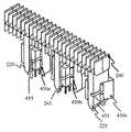
- FIG. 2Aillustrates an embodiment of the present invention.
- the heat sink 200has a longitudinal spine 210 with an opposing first side 211 and second side 212 .
- the opposing first side 211 and second side 212 of the spine 210are parallel, or at an angle other than a normal angle, to the surface of the board (i.e., abnormal).
- the spine 210is designed to be parallel with the surface of the board when the heat sink 200 is mounted on the board.
- Extending from the first side 211 of the spine 210are electronic device support legs 220 , 225 , configured so that each leg 220 , 225 can support two electronic devices or components on opposing side of the support legs 220 , 225 .
- FIG. 2Billustrates one side of a support leg 220 with an electronic component 240 mounted on it by screws, clips, or other generally recognized mounting method.
- FIG. 2Cillustrates the reverse side of the support leg 220 with another electronic component 245 mounted on it.
- the heat sink 200 illustrated in FIG. 2Ahas four electronic device support legs 220 , 225 and can mount eight electronic components 240 , 245 .
- the support legs 220 , 225have a thermal pad (not shown) covering at least a portion thereof.
- two of the support legs 220can be used to attach or mount the heat sink 200 to a circuit or wiring board and thus can serve as support legs for the heat sink 200 .
- At the end of each of the two legs 220 that attach to the circuit or wiring boardare pins 221 that engage corresponding ports on the board (not shown).
- the pins 221will have snaps or a claw type of fastener to secure the heat sink 200 to the board. This method of mounting is superior to prior art methods because it provides more mechanical stability and eliminates the need for additional fasteners. This aspect of the present invention is discussed in more detail below with respect of FIG. 4 B.
- cooling fins 230Extending from the second side 212 of the spine 210 are several cooling fins 230 . Although this embodiment has a symmetrical array of cooling fins 230 , those skilled in the art will recognize that cooling fins 230 may be of a varying length and may extend from the second side at varying angles and still be within the scope of the claimed invention such as the embodiment illustrated in FIG. 2 D.
- the heat sink 200has supplemental cooling fins 231 , 232 extending from the first side 211 . As shown in FIG. 2A, some of the supplemental cooling fins 232 extending from the first side 211 are substantially longer than the other fins 231 in order to provide improved cooling performance at low air velocities.
- the actual number and length of cooling fins 230 , 231 , 232 used on a heat sink 200can vary and still be within the intended scope of the invention.
- each cooling fin 230 , 231 , 232has a leading edge 235 over which air flow generated by the cooling fan first passes. As the airflow travels past the leading edge 235 , a boundary layer forms along the cooling fin 230 , 231 , 232 surface. The thickness of the boundary layer at the leading edge 235 approaches zero and increases the further the airflow progresses away from the leading edge 235 along the fin 230 , 231 , 232 surface across the depth of the heat sink 200 .
- the air temperature at the leading edge 235is the ambient temperature of the air and increases as the distance increases along the surface of the cooling fin 230 , 231 , 232 away from the leading edge 235 .
- heatis transferred by conduction and convection into the air with the rate of heat transfer increasing with the difference in temperature between the heat sink 200 and the air.
- the plurality of cooling fins 230 , 231 , 232have a depth (D) substantially less than the width (W) of the heat sink 200 , which gives this unique heat sink an exceptional cooling efficiency.
- the depth to width ratio of the fins 230 , 231 , 232 and spine, respectivelymay range from about 1 to 5 or 1 to 10. However, in a particularly useful embodiment, the ratio is 1 to 5; that is, the depth (D) of each fin 230 , 231 , 232 is 1 ⁇ 5 of the width (W) of the spine 210 of the heat sink 230 .
- the illustrated heat sink 200is particularly efficient because of the abundance of leading edges 235 and because of the efficient depth to width ratio as previously discussed. This unique heat sink therefore provides a maximum amount of heat transfer from several electrical components attached to the heat sink while using a fraction of the space and weight that would be required if prior art heat sinks were used.
- the depth of the heat sink 200is dictated by the size of the components 240 , 245 associated with it. In particularly efficient embodiments, the heat sink's 200 depth is preferably only slightly larger than the depth of the largest component 240 , 245 .
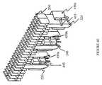
- FIG. 3illustrated is a circuit board 300 with a heat sink 200 installed thereon in a preferable configuration.
- the circuit board 300includes a fan 310 that moves air across the circuit board 300 .
- the heat sink 200is installed in such a way as to orient its width (W) in a direction perpendicular to the air flow, which is indicated by the arrow.
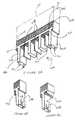
- FIG. 4Aillustrated is an embodiment of a clip 400 that, preferably, is used for fastening electronic devices to the electronic device support legs 220 , 225 .
- a clip 400that, preferably, is used for fastening electronic devices to the electronic device support legs 220 , 225 .
- electronic devicescan also be fastened to the electronic device support legs 220 , 225 by other methods.
- the clip 400may be a resilient strip 402 that is bent so that it has a first clamping surface 410 at the end of a first opposing surface member 415 and a second clamping surface 420 at the end of a second opposing surface member 425 , with the two clamping surfaces 410 , 420 in opposition to one another.
- the resilient strip 402has sufficient spring-like elasticity so that the two opposing surface members 415 , 425 are predisposed to return to their original shape when displaced.
- the opposing first and second surface members 415 , 425are spread apart by using a spreading device inserted in the spreading slots 411 , 421 located at the outer edges of the clamping surfaces 410 , 420 .
- Thisprovides an efficient, quick and easy way to attach electrical components to the heat sink 200 without having to use screws or other types of fasteners.
- a fastening pin 440that can be used to secure and align the clip 400 to a circuit or wiring board on which the heat sink 200 is mounted.
- the fastening pin 440is configured to be received by a corresponding hole or opening formed on the circuit board and may be nickel and tin plated to allow for ease of soldering to the circuit board.
- the pin 440can also be used to provide a path to electrically connect the component mounted on the clip 400 to the rest of the circuit mounted on the board.
- the clip 400may have a fastening pin 440 on opposing ends of the arcuate portion 405 so that the possibility of incorrectly orienting the clip 400 is eliminated.
- FIG. 4Billustrates one way in which the clip 400 can be used to install an electrical component onto a device support leg 225 of the heat sink 200 .
- FIG. 4Cillustrated is an alternative embodiment clip 450 that is also preferably used for fastening electronic devices 245 to the electronic device support legs 220 , 225 .
- the alternative embodiment clip 450is useful with the heat sink 200 described above, however, it is also equally useful with other similar heat sinks.
- the alternative embodiment clip 450varies from the clip 400 illustrated in FIG. 4 A.
- the alternative embodiment clip 450includes a retaining arm 455 extending from the resilient strip 402 and, that is configured to extend at least partially around the electronic device support or the electronic device, and thereby partially retain the electronic device against the electronic device support.
- the retaining arm 455 in one embodimentis a strip of metal that extends from the resilient strip 402 and has a bent end.
- the angle at which the end is bentmay vary, for example the angle may range from about 45° to about 180°. However, the angle should be large enough to provide a restraining force against either the electronic device 245 or the electronic device support legs 220 , 225 .
- the retaining arm 455is a footed retaining arm; that is, the end is bent at about a 90° angle.
- the alternative embodiment clip 450may further include at least one hole 460 located therein.
- the hole 460in a preferred embodiment, could be configured to receive an extensor portion from the electronic device support legs 220 , 225 , and prevent the alternative embodiment clip 450 from sliding along the electronic device support legs 220 , 225 .
- each alternative embodiment clip 450 a, 450 b, 450 cmay be used to fasten one, or a plurality of electronic devices 245 , to the electronic device support legs 220 , 225 .
- FIG. 4Eillustrated are the alternative embodiment clips 450 a, 450 b, 450 c fastened to the electronic device support legs 220 , 225 .
- Alternative embodiment clip 450 billustrates that, in one embodiment, the retaining arm 455 may wrap around an opposing surface of the electronic device 245 , and prevent the alternative embodiment clip 450 b from accidentally retreating from the electrical device.
- Alternative embodiment clip 450 cillustrates that, in an alternative embodiment, the retaining arm 455 may wrap around an opposing surface of the electronic device support leg 225 , and prevent the alternative embodiment clip 450 c from accidentally retreating from the electrical component or the electronic device support leg 225 .
- the alternative embodiment clip 450may be a metallic alloy, and more specifically, may have a sufficient spring-like elasticity so that the two opposing surface members 415 , 425 are predisposed to return to their original shape when displaced.
- FIG. 5Aillustrated is an embodiment of a heat sink 500 constructed in accordance with the present invention that has improved heat transfer characteristics.
- FIG. 5Billustrates a cross section view of this heat sink 500 embodiment showing a low drag shaped spine 510 , such as that typically associated with an aircraft wing.
- FIG. 5Cis a top view of the heat sink 500 embodiment showing the cooling fins 520 with a low drag shape such as that typically associated with an aircraft wing. This embodiment minimizes pressure drag such that substantially all of the pressure drop across the heat sink 500 is related to heat transfer.
- the heat transfer characteristics of the clip 400 , 450can also be improved by providing the clip 400 with a low drag shape similar to that of the fins, as discussed above. In such embodiments, the air flows across the clip 400 , 450 surface with minimal pressure drag.
- the heat sink 200can be formed by any well known extrusion, casting, machining, or other manufacturing method. In a preferred embodiment, the heat sink 200 is extruded in such a way that the advantageous embodiments of the heat sink 200 , as discussed above, will be incorporated.
- the required electrical components 240 , 245are attached to the electrical component support legs 220 , 225 by using the above-discussed clip 400 .
- the heat sinkis then mounted on a printed wiring or circuit board on which various electrical components electrically have been attached.
- the printed wiring or circuit boardincludes mounting holes configured to receive the heat sink's 200 mounting pins 221 .
- the heat sinkis then coupled to the printed wiring board by way of the mounting pins 221 engaging the board's mounting holes.
- the boardtypically has a cooling fan adjacent to the circuit or wiring board in order to provide cooling air transverse to the width of the heat sink 200 .
- the boardcan include any embodiment or feature of the invention described herein and can be used in any electronic system, including a telecommunication, computer, or a power distribution system.
Landscapes
- Engineering & Computer Science (AREA)
- Physics & Mathematics (AREA)
- Condensed Matter Physics & Semiconductors (AREA)
- General Physics & Mathematics (AREA)
- Computer Hardware Design (AREA)
- Microelectronics & Electronic Packaging (AREA)
- Power Engineering (AREA)
- Chemical & Material Sciences (AREA)
- Materials Engineering (AREA)
- Cooling Or The Like Of Electrical Apparatus (AREA)
Abstract
Description
Claims (9)
Priority Applications (1)
| Application Number | Priority Date | Filing Date | Title |
|---|---|---|---|
| US09/624,102US6310776B1 (en) | 1999-03-01 | 2000-07-24 | Transverse mountable heat sink for use in an electronic device |
Applications Claiming Priority (2)
| Application Number | Priority Date | Filing Date | Title |
|---|---|---|---|
| US09/259,772US6201699B1 (en) | 1999-03-01 | 1999-03-01 | Transverse mountable heat sink for use in an electronic device |
| US09/624,102US6310776B1 (en) | 1999-03-01 | 2000-07-24 | Transverse mountable heat sink for use in an electronic device |
Related Parent Applications (1)
| Application Number | Title | Priority Date | Filing Date |
|---|---|---|---|
| US09/259,772Continuation-In-PartUS6201699B1 (en) | 1999-03-01 | 1999-03-01 | Transverse mountable heat sink for use in an electronic device |
Publications (1)
| Publication Number | Publication Date |
|---|---|
| US6310776B1true US6310776B1 (en) | 2001-10-30 |
Family
ID=46257166
Family Applications (1)
| Application Number | Title | Priority Date | Filing Date |
|---|---|---|---|
| US09/624,102Expired - LifetimeUS6310776B1 (en) | 1999-03-01 | 2000-07-24 | Transverse mountable heat sink for use in an electronic device |
Country Status (1)
| Country | Link |
|---|---|
| US (1) | US6310776B1 (en) |
Cited By (14)
| Publication number | Priority date | Publication date | Assignee | Title |
|---|---|---|---|---|
| US6515858B2 (en)* | 2000-06-06 | 2003-02-04 | Unipower Corporation | Thermal distribution system |
| US6535383B2 (en)* | 2001-07-09 | 2003-03-18 | Intel Corporation | Clamshell heatsink |
| US20040187307A1 (en)* | 2001-06-15 | 2004-09-30 | Wong Chee Tieng | Heat sink |
| US20050013120A1 (en)* | 2003-07-18 | 2005-01-20 | Kechuan Liu | Configurable heat sink with matrix clipping system |
| US20060158859A1 (en)* | 2005-01-14 | 2006-07-20 | Funai Electric Co., Ltd. | Power supply and fixing structure of heatsink and circuit board applicable the same |
| US20080089034A1 (en)* | 2006-10-13 | 2008-04-17 | Dell Products L.P. | Heat dissipation apparatus utilizing empty component slot |
| US20090016026A1 (en)* | 2007-06-29 | 2009-01-15 | Markus Meier | Switching device with two controlled phases |
| US20090290310A1 (en)* | 2008-05-26 | 2009-11-26 | Kabushiki Kaisha Toyota Jidoshokki | Structure and method for mounting a heat-generating component |
| US20130153193A1 (en)* | 2011-07-13 | 2013-06-20 | Delta Electronics (Shanghai) Co.,Ltd. | Bidirectional heat sink for package element and method for assembling the same |
| USD718336S1 (en)* | 2012-09-07 | 2014-11-25 | Apple Inc. | Component for an electronic device |
| US9509102B2 (en)* | 2015-01-16 | 2016-11-29 | Tyco Electronics Corporation | Pluggable module for a communication system |
| US20170060199A1 (en)* | 2015-08-25 | 2017-03-02 | Samsung Electronics Co., Ltd. | Solid State Drive Apparatus |
| US20180355737A1 (en)* | 2017-06-09 | 2018-12-13 | United Technologies Corporation | Stator assembly with retention clip for gas turbine engine |
| US10667423B2 (en)* | 2018-10-26 | 2020-05-26 | Dell Products L.P. | Connector cooling and status indicator system |
Citations (23)
| Publication number | Priority date | Publication date | Assignee | Title |
|---|---|---|---|---|
| US3219885A (en)* | 1961-03-20 | 1965-11-23 | Gen Motors Corp | Transistor heat dissipator |
| US3220471A (en)* | 1963-01-15 | 1965-11-30 | Wakefield Engineering Co Inc | Heat transfer |
| US3519889A (en)* | 1967-11-06 | 1970-07-07 | Motorola Inc | Assembly with transistor heat dissipation |
| US3566959A (en)* | 1969-07-17 | 1971-03-02 | Controlled Power Corp | Heat sink |
| US4027206A (en)* | 1975-01-27 | 1977-05-31 | L. H. Research | Electronic cooling chassis |
| US4235285A (en)* | 1979-10-29 | 1980-11-25 | Aavid Engineering, Inc. | Self-fastened heat sinks |
| US4588023A (en)* | 1980-06-16 | 1986-05-13 | Showa Aluminum Corporation | Device for releasing heat |
| US4602315A (en)* | 1984-08-24 | 1986-07-22 | Thermalloy Incorporated | Compensating roll pin for heat sink mounting |
| US4899255A (en)* | 1988-07-25 | 1990-02-06 | Motorola Inc. | Heat sink clip and assembly and method of manufacture |
| US5109318A (en)* | 1990-05-07 | 1992-04-28 | International Business Machines Corporation | Pluggable electronic circuit package assembly with snap together heat sink housing |
| US5170325A (en)* | 1990-10-10 | 1992-12-08 | Robert Bosch Gmbh | Spring element for a group of components of an electronic control device |
| US5343362A (en)* | 1994-01-07 | 1994-08-30 | Zytec Corporation | Heat sink assembly |
| US5343361A (en)* | 1993-06-11 | 1994-08-30 | The Whitaker Corporation | Thermal junction for card edges in a card cage and ground clip therefor |
| US5461542A (en)* | 1992-12-18 | 1995-10-24 | Robert Bosch Gmbh | Multi-board electrical control device |
| US5507092A (en)* | 1995-06-06 | 1996-04-16 | Hisateru Akachi | L-type heat sink |
| US5719745A (en)* | 1995-07-12 | 1998-02-17 | International Business Machines Corporation | Extended surface cooling for chip stack applications |
| US5808869A (en)* | 1996-10-22 | 1998-09-15 | Compaq Computer Corporation | Method and apparatus for transferring heat from a PCMCIA card |
| US5854738A (en)* | 1997-05-30 | 1998-12-29 | Intel Corporation | Apparatus for supporting a cooling assembly coupled to an integrated circuit |
| US5870286A (en)* | 1997-08-20 | 1999-02-09 | International Business Machines Corporation | Heat sink assembly for cooling electronic modules |
| US5927386A (en)* | 1998-08-24 | 1999-07-27 | Macase Industrial Group Ga., Inc. | Computer hard drive heat sink assembly |
| US5973921A (en)* | 1997-11-03 | 1999-10-26 | Lin; Yu-Chen | Fixation structure for the fan of the CPU heat dissipating device |
| US5995369A (en)* | 1997-06-03 | 1999-11-30 | Patent-Treuhand-Gesellschaft Fuer Elektrische Gluelampen Mbh | Cooling plate connecting clip for power semiconductors |
| US6049459A (en)* | 1997-11-17 | 2000-04-11 | Lucent Technologies, Inc. | Nesting clamps for electrical components |
- 2000
- 2000-07-24USUS09/624,102patent/US6310776B1/ennot_activeExpired - Lifetime
Patent Citations (23)
| Publication number | Priority date | Publication date | Assignee | Title |
|---|---|---|---|---|
| US3219885A (en)* | 1961-03-20 | 1965-11-23 | Gen Motors Corp | Transistor heat dissipator |
| US3220471A (en)* | 1963-01-15 | 1965-11-30 | Wakefield Engineering Co Inc | Heat transfer |
| US3519889A (en)* | 1967-11-06 | 1970-07-07 | Motorola Inc | Assembly with transistor heat dissipation |
| US3566959A (en)* | 1969-07-17 | 1971-03-02 | Controlled Power Corp | Heat sink |
| US4027206A (en)* | 1975-01-27 | 1977-05-31 | L. H. Research | Electronic cooling chassis |
| US4235285A (en)* | 1979-10-29 | 1980-11-25 | Aavid Engineering, Inc. | Self-fastened heat sinks |
| US4588023A (en)* | 1980-06-16 | 1986-05-13 | Showa Aluminum Corporation | Device for releasing heat |
| US4602315A (en)* | 1984-08-24 | 1986-07-22 | Thermalloy Incorporated | Compensating roll pin for heat sink mounting |
| US4899255A (en)* | 1988-07-25 | 1990-02-06 | Motorola Inc. | Heat sink clip and assembly and method of manufacture |
| US5109318A (en)* | 1990-05-07 | 1992-04-28 | International Business Machines Corporation | Pluggable electronic circuit package assembly with snap together heat sink housing |
| US5170325A (en)* | 1990-10-10 | 1992-12-08 | Robert Bosch Gmbh | Spring element for a group of components of an electronic control device |
| US5461542A (en)* | 1992-12-18 | 1995-10-24 | Robert Bosch Gmbh | Multi-board electrical control device |
| US5343361A (en)* | 1993-06-11 | 1994-08-30 | The Whitaker Corporation | Thermal junction for card edges in a card cage and ground clip therefor |
| US5343362A (en)* | 1994-01-07 | 1994-08-30 | Zytec Corporation | Heat sink assembly |
| US5507092A (en)* | 1995-06-06 | 1996-04-16 | Hisateru Akachi | L-type heat sink |
| US5719745A (en)* | 1995-07-12 | 1998-02-17 | International Business Machines Corporation | Extended surface cooling for chip stack applications |
| US5808869A (en)* | 1996-10-22 | 1998-09-15 | Compaq Computer Corporation | Method and apparatus for transferring heat from a PCMCIA card |
| US5854738A (en)* | 1997-05-30 | 1998-12-29 | Intel Corporation | Apparatus for supporting a cooling assembly coupled to an integrated circuit |
| US5995369A (en)* | 1997-06-03 | 1999-11-30 | Patent-Treuhand-Gesellschaft Fuer Elektrische Gluelampen Mbh | Cooling plate connecting clip for power semiconductors |
| US5870286A (en)* | 1997-08-20 | 1999-02-09 | International Business Machines Corporation | Heat sink assembly for cooling electronic modules |
| US5973921A (en)* | 1997-11-03 | 1999-10-26 | Lin; Yu-Chen | Fixation structure for the fan of the CPU heat dissipating device |
| US6049459A (en)* | 1997-11-17 | 2000-04-11 | Lucent Technologies, Inc. | Nesting clamps for electrical components |
| US5927386A (en)* | 1998-08-24 | 1999-07-27 | Macase Industrial Group Ga., Inc. | Computer hard drive heat sink assembly |
Cited By (23)
| Publication number | Priority date | Publication date | Assignee | Title |
|---|---|---|---|---|
| US6515858B2 (en)* | 2000-06-06 | 2003-02-04 | Unipower Corporation | Thermal distribution system |
| US20040187307A1 (en)* | 2001-06-15 | 2004-09-30 | Wong Chee Tieng | Heat sink |
| US6535383B2 (en)* | 2001-07-09 | 2003-03-18 | Intel Corporation | Clamshell heatsink |
| US20050013120A1 (en)* | 2003-07-18 | 2005-01-20 | Kechuan Liu | Configurable heat sink with matrix clipping system |
| US7151669B2 (en)* | 2003-07-18 | 2006-12-19 | Kechuan K Liu | Configurable heat sink with matrix clipping system |
| US20060158859A1 (en)* | 2005-01-14 | 2006-07-20 | Funai Electric Co., Ltd. | Power supply and fixing structure of heatsink and circuit board applicable the same |
| US7580264B2 (en)* | 2005-01-14 | 2009-08-25 | Funai Electric Co., Ltd. | Power supply and fixing structure of heatsink and circuit board applicable to the same |
| US20080089034A1 (en)* | 2006-10-13 | 2008-04-17 | Dell Products L.P. | Heat dissipation apparatus utilizing empty component slot |
| US7480147B2 (en)* | 2006-10-13 | 2009-01-20 | Dell Products L.P. | Heat dissipation apparatus utilizing empty component slot |
| US7626824B2 (en)* | 2007-06-29 | 2009-12-01 | Siemens Aktiengesellschaft | Switching device with two controlled phases |
| US20090016026A1 (en)* | 2007-06-29 | 2009-01-15 | Markus Meier | Switching device with two controlled phases |
| US20090290310A1 (en)* | 2008-05-26 | 2009-11-26 | Kabushiki Kaisha Toyota Jidoshokki | Structure and method for mounting a heat-generating component |
| US7778036B2 (en)* | 2008-05-26 | 2010-08-17 | Kabushiki Toyota Jidoshokki | Structure and method for mounting a heat-generating component |
| US20130153193A1 (en)* | 2011-07-13 | 2013-06-20 | Delta Electronics (Shanghai) Co.,Ltd. | Bidirectional heat sink for package element and method for assembling the same |
| USD718336S1 (en)* | 2012-09-07 | 2014-11-25 | Apple Inc. | Component for an electronic device |
| US9509102B2 (en)* | 2015-01-16 | 2016-11-29 | Tyco Electronics Corporation | Pluggable module for a communication system |
| US20170060199A1 (en)* | 2015-08-25 | 2017-03-02 | Samsung Electronics Co., Ltd. | Solid State Drive Apparatus |
| US9958914B2 (en)* | 2015-08-25 | 2018-05-01 | Samsung Electronics Co., Ltd. | Solid state drive apparatus |
| US10289174B2 (en) | 2015-08-25 | 2019-05-14 | Samsung Electronics Co., Ltd. | Solid state drive apparatus |
| US10551885B2 (en) | 2015-08-25 | 2020-02-04 | Samsung Electronics Co., Ltd. | Solid state drive apparatus |
| US20180355737A1 (en)* | 2017-06-09 | 2018-12-13 | United Technologies Corporation | Stator assembly with retention clip for gas turbine engine |
| US10767503B2 (en)* | 2017-06-09 | 2020-09-08 | Raytheon Technologies Corporation | Stator assembly with retention clip for gas turbine engine |
| US10667423B2 (en)* | 2018-10-26 | 2020-05-26 | Dell Products L.P. | Connector cooling and status indicator system |
Similar Documents
| Publication | Publication Date | Title |
|---|---|---|
| US6201699B1 (en) | Transverse mountable heat sink for use in an electronic device | |
| US6310776B1 (en) | Transverse mountable heat sink for use in an electronic device | |
| US7891411B2 (en) | Heat dissipation device having a fan for dissipating heat generated by at least two electronic components | |
| US4872505A (en) | Heat sink for an electronic device | |
| US7079396B2 (en) | Memory module cooling | |
| US7349221B2 (en) | Device for increased thermal conductivity between a printed wiring assembly and a chassis | |
| US7414844B2 (en) | Liquid cooled heat sink with cold plate retention mechanism | |
| US5574626A (en) | Add-on heat sink | |
| US6603665B1 (en) | Heat dissipating assembly with thermal plates | |
| JPH02305498A (en) | Cold plate assembly | |
| US6252773B1 (en) | Heat sink attachment apparatus and method | |
| JPH0823182A (en) | Equipment and method for dissipating heat of integrated circuit | |
| US7057895B2 (en) | Thermal standoff for close proximity thermal management | |
| US5829515A (en) | Heat dissipator with multiple thermal cooling paths | |
| US20040200608A1 (en) | Plate fins with vanes for redirecting airflow | |
| US7265985B2 (en) | Heat sink and component support assembly | |
| US6483704B2 (en) | Microprocessor heat sink retention module | |
| US7382615B2 (en) | Heat dissipation device | |
| US5999405A (en) | PCB module support system | |
| US6906923B2 (en) | Heat sink clip and method | |
| US6330160B1 (en) | Component retention clip for a heat sink assembly | |
| EP0246432B1 (en) | Fluid impingement heatsink with crossflow capability | |
| US7248479B2 (en) | Thermal management for hot-swappable module | |
| WO2002021889A1 (en) | Heatsink retainer | |
| US6172873B1 (en) | Multi-electronic module mounting and retention mechanism |
Legal Events
| Date | Code | Title | Description |
|---|---|---|---|
| AS | Assignment | Owner name:LUCENT TECHNOLOGIES, INC., NEW JERSEY Free format text:ASSIGNMENT OF ASSIGNORS INTEREST;ASSIGNORS:BYRNE, VINCENT;FONTANA, EDWARD C.;SANDAGE, RALPH;AND OTHERS;REEL/FRAME:011004/0274 Effective date:20000720 | |
| STCF | Information on status: patent grant | Free format text:PATENTED CASE | |
| FPAY | Fee payment | Year of fee payment:4 | |
| FEPP | Fee payment procedure | Free format text:PAYOR NUMBER ASSIGNED (ORIGINAL EVENT CODE: ASPN); ENTITY STATUS OF PATENT OWNER: LARGE ENTITY | |
| FPAY | Fee payment | Year of fee payment:8 | |
| FPAY | Fee payment | Year of fee payment:12 | |
| AS | Assignment | Owner name:PROVENANCE ASSET GROUP LLC, CONNECTICUT Free format text:ASSIGNMENT OF ASSIGNORS INTEREST;ASSIGNORS:NOKIA TECHNOLOGIES OY;NOKIA SOLUTIONS AND NETWORKS BV;ALCATEL LUCENT SAS;REEL/FRAME:043877/0001 Effective date:20170912 Owner name:NOKIA USA INC., CALIFORNIA Free format text:SECURITY INTEREST;ASSIGNORS:PROVENANCE ASSET GROUP HOLDINGS, LLC;PROVENANCE ASSET GROUP LLC;REEL/FRAME:043879/0001 Effective date:20170913 Owner name:CORTLAND CAPITAL MARKET SERVICES, LLC, ILLINOIS Free format text:SECURITY INTEREST;ASSIGNORS:PROVENANCE ASSET GROUP HOLDINGS, LLC;PROVENANCE ASSET GROUP, LLC;REEL/FRAME:043967/0001 Effective date:20170913 | |
| AS | Assignment | Owner name:ALCATEL-LUCENT USA INC., NEW JERSEY Free format text:CHANGE OF NAME;ASSIGNOR:LUCENT TECHNOLOGIES INC.;REEL/FRAME:049887/0613 Effective date:20081101 | |
| AS | Assignment | Owner name:NOKIA US HOLDINGS INC., NEW JERSEY Free format text:ASSIGNMENT AND ASSUMPTION AGREEMENT;ASSIGNOR:NOKIA USA INC.;REEL/FRAME:048370/0682 Effective date:20181220 | |
| AS | Assignment | Owner name:PROVENANCE ASSET GROUP LLC, CONNECTICUT Free format text:RELEASE BY SECURED PARTY;ASSIGNOR:CORTLAND CAPITAL MARKETS SERVICES LLC;REEL/FRAME:058983/0104 Effective date:20211101 Owner name:PROVENANCE ASSET GROUP HOLDINGS LLC, CONNECTICUT Free format text:RELEASE BY SECURED PARTY;ASSIGNOR:CORTLAND CAPITAL MARKETS SERVICES LLC;REEL/FRAME:058983/0104 Effective date:20211101 Owner name:PROVENANCE ASSET GROUP LLC, CONNECTICUT Free format text:RELEASE BY SECURED PARTY;ASSIGNOR:NOKIA US HOLDINGS INC.;REEL/FRAME:058363/0723 Effective date:20211129 Owner name:PROVENANCE ASSET GROUP HOLDINGS LLC, CONNECTICUT Free format text:RELEASE BY SECURED PARTY;ASSIGNOR:NOKIA US HOLDINGS INC.;REEL/FRAME:058363/0723 Effective date:20211129 | |
| AS | Assignment | Owner name:RPX CORPORATION, CALIFORNIA Free format text:ASSIGNMENT OF ASSIGNORS INTEREST;ASSIGNOR:PROVENANCE ASSET GROUP LLC;REEL/FRAME:059352/0001 Effective date:20211129 |