US6310740B1 - Disk drive including N-current preamplifier for generating N-independently controlled write currents - Google Patents
Disk drive including N-current preamplifier for generating N-independently controlled write currentsDownload PDFInfo
- Publication number
- US6310740B1 US6310740B1US09/342,670US34267099AUS6310740B1US 6310740 B1US6310740 B1US 6310740B1US 34267099 AUS34267099 AUS 34267099AUS 6310740 B1US6310740 B1US 6310740B1
- Authority
- US
- United States
- Prior art keywords
- current
- write
- setting control
- control signals
- local
- Prior art date
- Legal status (The legal status is an assumption and is not a legal conclusion. Google has not performed a legal analysis and makes no representation as to the accuracy of the status listed.)
- Expired - Lifetime
Links
- 238000013442quality metricsMethods0.000abstractdescription27
- 238000012360testing methodMethods0.000abstractdescription12
- 238000004519manufacturing processMethods0.000abstractdescription9
- 238000000034methodMethods0.000description34
- 238000005259measurementMethods0.000description15
- 238000010586diagramMethods0.000description8
- 230000001939inductive effectEffects0.000description8
- 230000008569processEffects0.000description8
- 230000007704transitionEffects0.000description8
- 230000004907fluxEffects0.000description5
- 230000004044responseEffects0.000description5
- 238000012545processingMethods0.000description4
- 238000001514detection methodMethods0.000description3
- 230000006870functionEffects0.000description3
- 238000007476Maximum LikelihoodMethods0.000description2
- 230000002238attenuated effectEffects0.000description2
- 230000008859changeEffects0.000description2
- 230000001427coherent effectEffects0.000description2
- 238000001914filtrationMethods0.000description2
- 230000003287optical effectEffects0.000description2
- 229920006395saturated elastomerPolymers0.000description2
- UTMWFJSRHLYRPY-UHFFFAOYSA-N3,3',5,5'-tetrachlorobiphenylChemical compoundClC1=CC(Cl)=CC(C=2C=C(Cl)C=C(Cl)C=2)=C1UTMWFJSRHLYRPY-UHFFFAOYSA-N0.000description1
- 229910000531Co alloyInorganic materials0.000description1
- 230000002411adverseEffects0.000description1
- 230000000740bleeding effectEffects0.000description1
- 239000004020conductorSubstances0.000description1
- 238000012937correctionMethods0.000description1
- 238000012804iterative processMethods0.000description1
- 239000000696magnetic materialSubstances0.000description1
- 230000005415magnetizationEffects0.000description1
- 230000007246mechanismEffects0.000description1
- 239000000203mixtureSubstances0.000description1
- 230000009467reductionEffects0.000description1
- 238000005070samplingMethods0.000description1
- 239000010409thin filmSubstances0.000description1
- 238000012795verificationMethods0.000description1
Images


Classifications
- G—PHYSICS
- G11—INFORMATION STORAGE
- G11B—INFORMATION STORAGE BASED ON RELATIVE MOVEMENT BETWEEN RECORD CARRIER AND TRANSDUCER
- G11B5/00—Recording by magnetisation or demagnetisation of a record carrier; Reproducing by magnetic means; Record carriers therefor
- G11B5/48—Disposition or mounting of heads or head supports relative to record carriers ; arrangements of heads, e.g. for scanning the record carrier to increase the relative speed
- G11B5/58—Disposition or mounting of heads or head supports relative to record carriers ; arrangements of heads, e.g. for scanning the record carrier to increase the relative speed with provision for moving the head for the purpose of maintaining alignment of the head relative to the record carrier during transducing operation, e.g. to compensate for surface irregularities of the latter or for track following
- G11B5/596—Disposition or mounting of heads or head supports relative to record carriers ; arrangements of heads, e.g. for scanning the record carrier to increase the relative speed with provision for moving the head for the purpose of maintaining alignment of the head relative to the record carrier during transducing operation, e.g. to compensate for surface irregularities of the latter or for track following for track following on disks
- G11B5/59633—Servo formatting
- G—PHYSICS
- G11—INFORMATION STORAGE
- G11B—INFORMATION STORAGE BASED ON RELATIVE MOVEMENT BETWEEN RECORD CARRIER AND TRANSDUCER
- G11B20/00—Signal processing not specific to the method of recording or reproducing; Circuits therefor
- G11B20/10—Digital recording or reproducing
- G—PHYSICS
- G11—INFORMATION STORAGE
- G11B—INFORMATION STORAGE BASED ON RELATIVE MOVEMENT BETWEEN RECORD CARRIER AND TRANSDUCER
- G11B5/00—Recording by magnetisation or demagnetisation of a record carrier; Reproducing by magnetic means; Record carriers therefor
- G11B5/012—Recording on, or reproducing or erasing from, magnetic disks
- G—PHYSICS
- G11—INFORMATION STORAGE
- G11B—INFORMATION STORAGE BASED ON RELATIVE MOVEMENT BETWEEN RECORD CARRIER AND TRANSDUCER
- G11B5/00—Recording by magnetisation or demagnetisation of a record carrier; Reproducing by magnetic means; Record carriers therefor
- G11B5/02—Recording, reproducing, or erasing methods; Read, write or erase circuits therefor
- G11B5/09—Digital recording
- G—PHYSICS
- G11—INFORMATION STORAGE
- G11B—INFORMATION STORAGE BASED ON RELATIVE MOVEMENT BETWEEN RECORD CARRIER AND TRANSDUCER
- G11B5/00—Recording by magnetisation or demagnetisation of a record carrier; Reproducing by magnetic means; Record carriers therefor
- G11B2005/0002—Special dispositions or recording techniques
- G11B2005/0005—Arrangements, methods or circuits
- G11B2005/001—Controlling recording characteristics of record carriers or transducing characteristics of transducers by means not being part of their structure
- G11B2005/0013—Controlling recording characteristics of record carriers or transducing characteristics of transducers by means not being part of their structure of transducers, e.g. linearisation, equalisation
- G—PHYSICS
- G11—INFORMATION STORAGE
- G11B—INFORMATION STORAGE BASED ON RELATIVE MOVEMENT BETWEEN RECORD CARRIER AND TRANSDUCER
- G11B5/00—Recording by magnetisation or demagnetisation of a record carrier; Reproducing by magnetic means; Record carriers therefor
- G11B5/02—Recording, reproducing, or erasing methods; Read, write or erase circuits therefor
- G11B5/027—Analogue recording
- G11B5/035—Equalising
Definitions
- the present inventionrelates to disk drives. More particularly, the present invention relates to a disk drive comprising a n-current preamplifier for generating n-independently controlled write currents for a plurality of heads.
- Magnetic disk drives for computer systemstypically employ an array of disks and associated read/write heads together with head positioning and spindle mechanics.
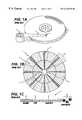
- This arrangement of heads and fixed disk arrayis referred to as a head disk assembly or HDA, an overview of which is provided in FIG. 1 A.
- Several magnetic disks 2 connected in an arrayare rotated by a spindle motor.
- Each recording surface (top and bottom) of each magnetic diskis accessed through a dedicated head 4 ; as the disks spin, a thin layer air-bearing forms between the heads 4 and the recording surface such that the heads 4 are said to “fly” just above the recording surface.
- the heads 4are connected to the distal end of actuator arms 6 which are connected to a pivot 8 actuated by a rotary voice coil motor (VCM).
- VCMrotary voice coil motor
- the recording surface of the magnetic diskis coated with a thin film medium (e.g., cobalt alloy) which is magnetized inductively by a write coil of the head 4 .
- the digital data being recordedmodulates a current passing through the write coil in order to inductively write a series of magnetic transitions onto the disk surface (recording surface) of the disk, where a preamplifier chip incorporated within the HDA performs the modulation function in response to the digital data.
- the datais written in the radially spaced, concentric tracks 10 which are partitioned into blocks of data referred to as data sectors 12 . Because the circumferential recording area increases from the inner to outer diameter tracks, more data can be stored in the outer diameter tracks.
- the recording surfaceis normally partitioned into a number of zones where each zone comprises a predetermined number of tracks. Data is then written to the recording surface at an increasing rate as the head traverses radially from the inner to outer diameter zones, thereby increasing the amount of data stored in the outer diameter tracks.
- FIG. 1Bwhich shows a disk partitioned into an inner diameter zone 14 comprising seven data sectors per track, and an outer diameter zone 16 comprising fourteen data sectors per track.
- the recording surfaceis actually partitioned into several zones with the data rate incrementally increasing from the inner to outer diameter zones in order to exploit the maximum storage capacity of the recording surface.
- the magnetic disks 2also comprise servo sectors 18 which are recorded at a regular interval and interleaved with the data sectors 12 as shown in FIG. 1B.
- a servo sectortypically comprises a preamble 20 and sync mark 22 for synchronizing to the servo sector; a servo data field 24 comprising coarse position information, such as a Gray coded track address, used to determine the radial location of the head with respect to the plurality of tracks; and a plurality of servo bursts 26 recorded at precise intervals and offsets from the track centerlines which provide fine head position information.
- a servo controllerWhen writing or reading data, a servo controller performs a “seek” operation to position the head over a desired track; as the head traverses radially over the recording surface, the Gray coded track addresses in the servo data field 24 provide coarse position information for the head with respect to the current and target track. When the head 4 reaches the target track, the servo controller performs a tracking operation wherein the servo bursts 26 provide fine position information used to maintain the head over the centerline of the track as the digital data is being written to or read from the recording surface.
- the servo sectors 18are written to the recording surfaces as part of the manufacturing process to enable the seek and tracking operations necessary to write and read the data sectors 12 .
- a common mechanism for writing the servo sectors to the recording surfacesis an external servo track writer which uses the write preamplifier electronics and heads within the HDA, but which uses separate control circuitry and servo mechanics for radially positioning the heads using well known techniques such as a laser interferometer.
- a significant cost reductioncan be achieved by a “self-servowriting” method which can use circuitry in the disk drive for writing the servo sectors.
- the analog write current setting 30adjusts the output current of driver circuits ( 34 0 - 34 N ) which supply the respective write currents ( 36 0 - 36 N ) to the heads 4 .
- Head select circuitry 38 within the preamplifierenables the output of the appropriate driver circuit ( 34 0 - 34 N ) over line 40 during normal operation of the disk drive, and it enables the output of all the driver circuits ( 34 0 - 34 N ) during servo track writing in order to write the servo sectors to all of the recording surfaces simultaneously.
- the digital write data 42 to be recorded to the surface of the disk 2modulates the operation of the driver circuits ( 34 0 - 34 N ) by alternating the polarity of the write current 36 ; for example, a digital “1” bit may modulate a positive write current and a digital “0” may modulate a negative write current.
- Noise in the disk drivemay induce errors when reading the track addresses and/or servo bursts which will degrade the performance of the disk drive by increasing seek times as well as increasing the bit error rate if the head is unable to maintain proper centerline tracking. Therefore, when the servo sectors are written to the recording surfaces, it is important that enough write current is supplied to each head to saturate the magnetic material on the recording surface so as to maximize the signal power during read back.
- Prior art servo track writersthat perform a bank servo write to all of the recording surfaces simultaneously would set the write current high enough to ensure that each head would be driven by enough current to saturate the recording surfaces.
- one pole of the inductive write elementis shared with one of the shields for the MR read element; this pole is consequently wider than the other pole of the inductive write element which causes significant fringing fields at the periphery of the write gap if the write current is set too high.
- the amount of write current necessary to saturate the recording surfacevaries between the MR heads in the disk array due to process variations in manufacturing the MR heads and the magnetic disks.
- using the prior art preamplifier of FIG. 4 to drive all the MR heads with a single write current high enough to ensure that all of the recording surfaces are saturatedmay inevitably drive at least one of the MR heads with too much write current and cause significant fringing fields.
- FIG. 2Ashows the two write poles of an MR head, where the second write pole is shared with a shield of the MR read element and therefore is wider than the first write pole.
- the view of the MR head in FIG. 2Ais looking up from the disk with the direction of the MR head and orientation of the track vertical to the page.
- flinging fieldsare generated at the periphery of the write gap due to the disparate pole widths. As illustrated, the flinging fields arc from the write pole forming flux lines perpendicular to the track which can effectively erase the recording surface.
- the width of the adverse flinging fieldsextends to the critical flux line, the flux line strong enough to change the magnetization of the recording surface, which is proportional to the strength of the write current.
- the write currentis too high causing wide erase bands at the edges of the track.
- FIG. 2BA more optimal write current is shown in FIG. 2B which is just strong enough to generate flux in the write gap to saturate the recording surface along the track, while creating only a narrow erase band due to the attenuated fringing fields.
- the magnetic transitions in the servo track addressesare recorded using a phase coherent Gray code meaning that the magnetic transitions in the track addresses of adjacent tracks differ by only two adjacent bit cells so that there is no intertrack interference when the head is between tracks during a seek operation.
- An erase band caused by the flinging fields of an MR headinterferes with the accurate detection of the track addresses by disrupting the phase coherent nature of the Gray code.
- the erase band at the edges of the servo burstsintroduces a non-linear distortion in the position error signal generated during tracking which offsets the centerline position of the head preventing optimal detection of the data sectors.
- the characteristics of the storage mediummay change from the inner diameter tracks to the outer diameter tracks such that more or less write current may be necessary to saturate the recording surface depending on the head's radial location.
- the characteristics of the erase band formed by the fringing fieldmay vary depending on the radial location of the head. As the head traverses radially over the disk, the poles of the write element will skew from the track centerline depending on the head's arc trajectory, which changes the characteristic of the erase band.
- the inventioncan be regarded as a n-current preamplifier for use in a disk drive comprising a plurality of recording surfaces and a corresponding plurality of heads.
- the n-current preamplifierincludes an input for receiving a plurality of current-setting control signals corresponding to the plurality of heads.
- the n-current preamplifierfurther includes a plurality of signal-to-current converters for converting the current-setting control signals into a plurality of write currents for the heads. Each write current has a magnitude that is independently controlled by a respective one of the current-setting control signals.
- the inventioncan also be regarded as a disk drive comprising a plurality of recording surfaces and a plurality of heads corresponding to the plurality of recording surfaces.
- the disk driveincludes a n-current preamplifier comprising an input for receiving a plurality of current-setting control signals corresponding to the plurality of heads.
- the n-current preamplifierfurther includes a plurality of signal-to-current converters for converting the current-setting control signals into a plurality of write currents for the heads.
- Each write currenthas a magnitude that is independently controlled by a respective one of the current-setting control signals.
- FIG. 1Aillustrates a conventional head disk assembly (HDA) within a conventional disk drive comprising an array of disks and associated heads positioned radially over the disk surfaces.
- HDAhead disk assembly
- FIG. 1Bshows a typical format for one of the disk surfaces in the disk array of FIG. 1A comprising a plurality of radially spaced, concentric data tracks partitioned into a number of data sectors and further comprising embedded servo sectors for positioning the heads over the disk surfaces while seeking and tracking.
- FIG. 1Cshows a typical format of an embedded servo sector comprising a preamble and sync mark for synchronizing to a servo data field comprising coarse track positioning information such as a track address, and further comprising servo bursts recorded at precise intervals and offsets with respect to the track's centerline which provide fine position information during tracking.
- FIG. 2Aillustrates the geometry of the write poles in a magneto-resistive (MR) head and how the disparity in the width of the write poles generates flinging fields at the periphery of the write gap which results in wide erase bands at the edges of the servo tracks if the write current is set too high.
- MRmagneto-resistive
- FIG. 2Billustrates how the erase bands are attenuated in the MR head of FIG. 2A by optimizing the write current.
- FIG. 3Ais a block diagram of a disk drive comprising a HDA together with a read/write channel, disk controller and servo controller mounted on a printed circuit board (PCB), wherein the HDA comprises an-current preamplifier for generating independent write currents optimized for each head.
- PCBprinted circuit board
- FIG. 3Bshows the HDA of FIG. 3A inserted into an external servo track writer during manufacturing which calibrates the optimal write currents for each head in the disk array and then simultaneously writes the servo sectors to all of the recording surfaces in a bank servo write mode.
- FIG. 3Cshows a disk drive employing “self-servowriting” to write the servo sectors to all of the recording surfaces during manufacturing by calibrating the optimal write currents and performing the bank servo write operation internal to the disk drive.
- FIG. 4illustrates the composition of a conventional preamplifier which generates the same write current for each head while bank servo writing the disk array.
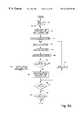
- FIG. 5Ais a block diagram of the n-current preamplifier of FIG. 3A comprising an input for receiving a plurality of current-setting control signals, and a plurality of signal-to-current converters for converting the current-setting control signals into independent write currents.
- FIG. 5Bshows one embodiment for the n-current preamplifier of FIG. 5A, wherein a plurality of registers store the current-setting control signals, and a plurality of digital-to-analog converters (DACs) and corresponding driver circuits constitute the signal-to-current converters for converting the current-setting control signals into independent write currents.
- DACsdigital-to-analog converters
- FIG. 5Cillustrates an alternative embodiment for the n-current preamplifier of FIG. 5A, wherein the independent write currents are generated by adding a global (coarse) write current setting generated for all of the heads to a local (fine) write current setting for each head in order to reduce the circuitry in the DACs as compared to the implementation of FIG. 5 B.
- FIG. 5Dshows yet another alternative embodiment for the n-current preamplifier of FIG. 5A which further reduces the circuitry used to generate the independent write currents by using a single register-DAC pair and a plurality of sample-and-hold (S/H) circuits for sampling the output of the DAC, wherein the DAC's register is set with the independent write current settings just prior to writing a servo sector to the recording surfaces.
- S/Hsample-and-hold
- FIG. 6Aillustrates an example embodiment for the driver circuits employed in the n-current preamplifier of FIGS. 5B-5D.
- FIG. 6Billustrates a conventional circuit for generating the same write current for all the heads in the prior art preamplifier of FIG. 4 .
- FIG. 7Ashows an example circuit for generating the independent write currents for each driver circuit in the n-current preamplifier of FIG. 5 B.
- FIG. 7Bshows an example circuit for generating the independent write currents for each driver circuit in the n-current preamplifier of FIG. 5 C.
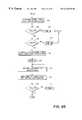
- FIGS. 8A-8Bare flow diagrams illustrating a write current calibration and bank servo writing procedure that employs the n-current preamplifier of FIG. 5 for calibrating independent write currents and simultaneously servo writing a plurality of recording surfaces.
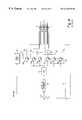
- FIG. 3 AAn overview of a disk drive 44 employing the aspects of the present invention is shown in FIG. 3 A.
- the disk drive 44is connected to a host computer via interface connection 46 .
- the host computertransmits user data to be stored to the disk drive, and receives information read from the disk drive 44 .
- the user datais stored on the recording surfaces of an array of magnetic disks 2 rotated by a spindle motor 48 located inside an HDA 49 .
- a voice coil motor (VCM) 50actuates a pivot 8 to rotate an array of actuator arms 6 with a plurality of heads 4 attached to the actuator arms 6 in order to position the heads 4 radially over the recording surfaces.
- Heads 4comprise an inductive write coil for writing magnetic transitions on the recording surface, and a magneto-resistive (MR) read element for reading the magnetic transitions.
- MRmagneto-resistive
- the recording surfaces of the magnetic disks 2comprise a plurality of concentric, radially spaced tracks 10 partitioned into a number of data sectors 12 as illustrated in FIG. 1 B.
- User datais written to the recording surface a data sector at a time; the recording surfaces comprise servo sectors 18 which facilitate positioning the head 4 over a desired data sector within a particular track 10 .
- a servo controller 52includes a track positioning system that processes Gray coded track addresses within the servo sectors 18 to position the head 4 with respect to the tracks 10 during seek operations, and it processes servo bursts within the servo sectors 18 to maintain the head over the centerline of the track (tracking) as data is written to or read from the disk 2 .
- the VCM 50 for positioning the heads 4is precisely controlled by the servo controller 52 in response to a position error formed from the track address and servo burst information.
- the servo controller 52also includes a spindle motor control system that controls a spindle motor 48 which rotates the array of magnetic disks.
- the spindle motor 48is controlled by the servo controller 52 when the disk drive is initially powered on in order to “spin-up” the disk array.
- the servo controller 52controls the spindle motor 48 so that the disk array rotates at a substantially constant angular velocity.
- a disk controller 54coordinates the operation of the disk drive by handling the host interface functions when a host request to write or read data is received, and controlling other components in the disk drive to effectuate the write and read operations to and from the disks 2 .
- a read/write channel 58comprises encoding circuitry for encoding the data prior to writing the digital write data 42 to the disk 2 , as well as signal processing circuitry for processing the analog read signal 62 when reading data from the disk 2 .
- An-current preamplifier 64(the details for which are described below) generates the write currents 66 i for each head 4 during write operations, and it preamplifies the analog read signal 65 i emanating from the head 4 during read operations.
- ECCerror correction code
- RLLrun-length limited
- the encoded write datais transferred over line 42 to the n-current preamplifier 64 where it modulates the write current 66 i in an inductive write coil of the head 4 in order to write a series of magnetic transitions on the recording surface of the disk 2 which represent the recorded data. For example, a “1” bit may modulate a positive write current and a “0” bit may modulate a negative write current.
- the disk controller 54programs the n-current prearnplifier 64 with a head select signal over line 70 for selecting the appropriate head 4 when the encoded user data is written to a particular recording surface.
- the MR element in the head 4senses the magnetic transitions recorded on the recording surface of disk 2 and generates analog read signal 65 i comprising polarity alternating pulses representing the recorded digital data.
- the n-current preamplifier 64preamplifies the analog read signal 65 i and transmits analog read signal 62 to the read/write channel 58 .
- the read/write channel 58comprises circuitry for evaluating the pulses in the analog read signal 62 in order to demodulate the recorded data.
- Itmay comprise a simple analog peak detector for detecting isolated pulses in the analog read signal 62 , or it may comprise a partial response/maximum likelihood (PRML) detector which samples the analog read signal 62 and then estimates the recorded digital data by evaluating the signal samples in context to determine a most likely data sequence associated with the signal samples.
- PRMLpartial response/maximum likelihood
- the preferred embodimentis to use the PRML read/write channel because it reduces the error rate for a given SNR and thus the overall storage capacity of the disk drive.
- a channel decoder in the read/write channel 58decodes the estimated data sequence which is then transferred to the disk controller 54 over line 68 for ECC decoding. After ECC decoding and integrity verification, the decoded user data is transferred to the host via the disk drive interface 46 .
- the read/write channel 58also detects the data in the servo sectors 18 which is transferred to the servo controller 52 over line 76 for positioning the heads 4 with respect to the tracks 10 during both read and write operations (seeking and tracking).
- the servo controller 52computes a coarse position error as the difference between the current track location of the head 4 as specified by the track address in the servo data field 24 of the servo sector 18 , and a target track provided by the disk controller 54 over line 78 .
- the servo controller 52computes a position error signal (PES) with respect to the track centerline from the position information provided by the servo bursts 26 ; the servo controller 52 makes fine adjustments to the VCM 50 in order to drive the PES to zero and thereby maintain centerline tracking while reading data from or writing data to the disk 2 .
- PESposition error signal
- the n-current preamplifier 64is typically implemented as a separate integrated chip located inside the HDA 49 near the actuator arms 6 of the actuator assembly in order to minimize noise interjected into the read/write signal over lines 65 and 66 which connect the n-current preamplifier 64 to the heads 4 .
- the remaining components shown in FIG. 3A, the read/write channel 58 , disk controller 54 , and servo controller 52may be implemented as separate chips or as a single integrated chip typically mounted on printed circuit board (PCB) 80 attached to the bottom of the HDA 49 and connected to the n-current preamplifier 64 through a cable conductor.
- PCBprinted circuit board
- the interface between the n-current preamplifier 64 and other circuitry located on the PCBis preferably implemented using a serial interface.
- FIG. 3Bshows the HDA 49 of FIG. 3A inserted into an external servo track writer 77 before the PCB 80 has been mounted to the HDA 49 .
- the external servo track writer 77comprises a “clock head” 79 positioned over one of the recording surfaces and a clock pattern generator 81 for writing a magnetic clock pattern in a track preferably at an outer diameter of the recording surface.
- the magnetic clock patternis read by the clock head 79 and processed by a timing circuit 83 which generates a timing clock 85 applied to a controller 87 .
- the controller 87preferably processes the timing clock 85 to derive the precise circumferential location of the heads 4 with respect to the tracks so that the servo sectors 18 are written at the same circumferential location from the inner to outer diameter tracks.
- Other suitable methodsare known in the art for generating the timing clock 85 , including an optical clock pattern recorded on an inner diameter of a recording surface which is read using an optical transducer comprising a light source and a photodetector.
- the external servo track writer 77further comprises a push pin 89 which is inserted into the HDA 49 and into a hole in the actuator arm 6 .
- a head positioner circuit 91suitably comprising a very fine resolution stepper motor, actuates the push pin 89 in order to precisely position the heads 4 radially over the disk 2 while writing the servo sectors (servo data and servo bursts).
- the controller 87applies a reverse direction bias current to the coil of the VCM 50 over line 93 in order to bias the actuator arm 6 against the push pin 89 to facilitate precise positioning of the heads 4 .
- the controller 87also applies a current to the coil of the spindle motor 48 over line 95 in order to spin up the disks 2 and then rotate the disks 2 at a substantially constant angular velocity.
- the controller 87executes a calibration procedure (the details of which are set forth below with respect to FIGS. 8A and 8B) in order to determine optimal write current-setting control signals for the plurality of heads 4 .
- the calibration procedure executed by the controller 87involves programming the current preamplifier 64 over line 70 with a write current-setting control signal for a particular head 4 , writing a test pattern (write data 42 ) to the respective recording surface, reading the test pattern, and processing the read signal 62 to generate a quality metric indicative of the quality of the write current setting.
- the external servo track writer 77comprises a quality metric measurement circuit 97 for processing the read signal 62 to generate the quality metric 99 evaluated by the controller 87 during the calibration process.
- the quality metric measurement circuit 97preferably computes an overwrite measurement which provides an indication of how well the write current saturates the recording surface.
- the overwrite measurementinvolves writing a low frequency test pattern to the recording surface and measuring the energy in the read signal at the low frequency upon read back, overwriting the low frequency test pattern with a high frequency test pattern, measuring the residual energy in the low frequency component of the read signal upon read back, and taking the ratio of the first low frequency energy measurement to the residual low frequency measurement (after the overwrite) to generate the overwrite measurement.
- the quality metric measurement circuit 97(in analog or discrete-time) filters the read signal 62 and measures the energy in the read signal 62 to generate the overwrite quality metric 99 .
- the controller 87programs the n-current preamplifier 64 over line 70 with the optimal write current-setting control signals and then performs the bank servo write operation by simultaneously writing the servo sectors 18 to all of the recording surfaces using the precise timing clock 85 .
- the servo sector datais passed from the controller 87 over write data line 42 , through the n-current preamplifier 64 , and over lines 66 connecting the n-current preamplifier 64 to the write coil of the heads 4 .
- An alternative method for writing the servo sectors to the recording surfaces of the disks 2 during manufacturingis to utilize the disk controller 54 , read/write channel 58 , and servo controller 52 already integrated into the disk drive 44 of FIG. 3A to “self-servo write” the servo sectors 18 .
- This techniquesuitably entails an iterative process wherein each servo track is written using information from a previously written servo track.
- the disk controller 54executes the calibration procedure and bank servo write operation described below.
- the disk controller 54programs the n-current preamplifier 64 over line 70 to select the appropriate head 4 and to set the appropriate write current-setting control signal, and the quality metric 74 used to calibrate the optimal write current setting is generated by the read/write channel 58 .
- the disk controller 54programs the n-current preamplifier 64 over line 70 with the optimal write current-setting control signals for all of the heads 4 and then simultaneously writes the servo sectors 18 to all of the recording surfaces.
- the servo sector datais transferred over fine 42 from the disk controller 54 through the read/write channel 58 (unmodified) to the n-current preamplifier 64 and over lines 66 connecting the n-current preamplifier 64 to the write coil of the heads 4 .
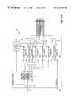
- n-current preamplifier 64comprises an input 103 for receiving a plurality of current-setting control signals over line 70 , and a plurality of signal-to-current converters ( 89 0 - 89 N ) for converting the current-setting control signals into a plurality of write currents ( 66 0 - 66 N ) for the heads 4 , wherein each write current ( 66 0 - 66 N ) has a magnitude that is independently controlled by a respective one of the current-setting control signals.
- a head select control signalis also received over line 70 and applied to a head select circuit 38 which selects all of the heads 4 when bank servo writing the servo sectors to all of the recording surfaces, and selects the appropriate head 4 when writing a user data sector to a particular recording surface during normal operation.
- the write data received over line 42 to be written to the recording surfaceare input into the signal-to-current converters ( 89 0 - 89 N ) to modulate the write currents ( 66 0 - 66 N ); for example, a “1” bit may modulate a positive write current and a “0” bit a negative write current in the coil of the head 4 .
- a “1” bitmay modulate a positive write current and a “0” bit a negative write current in the coil of the head 4 .
- the current-setting control signals received over line 70are stored in respective registers 102 and then converted into the appropriate write currents ( 66 0 - 66 N ) by the signal-to-current converters ( 89 0 - 89 N ).
- the signal-to-current converters ( 89 0 - 89 N )are illustrated in FIGS. 5B-5C.
- a plurality of DACs ( 90 0 - 90 N ) driven by a common current reference 92 output by current reference generator 94 and a plurality of driver circuits ( 100 0 - 100 N )constitute the signal-to-current converters ( 89 0 - 89 N ) of FIG. 5 A.
- Each of the DACs ( 90 0 - 90 N )generates an independent analog write current setting ( 96 0 - 96 N ) for independently setting the write current ( 66 0 - 66 N ) for each head 4 through the plurality of driver circuits ( 100 0 - 100 N ).
- the DACs ( 90 0 - 90 N )convert the current-setting control signals stored in registers 102 into the analog write currents settings ( 96 0 - 96 N ).
- the driver circuits ( 100 0 - 100 N ) of FIG. 5Bare modified to output independent write currents ( 66 0 - 66 N ) corresponding to the analog write current settings ( 96 0 - 96 N ) for each head 4 rather than output the same write current for all the heads as in the prior art preamplifier of FIG. 4 .
- the head select circuit 38When writing data to target data sector on a recording surface during normal operation, the head select circuit 38 enables the output of the appropriate driver circuit ( 100 0 - 100 N ) corresponding to the recording surface of the target data sector.
- the head select circuit 38When bank writing the servo sectors 18 , the head select circuit 38 enables the outputs of all the driver circuits ( 100 0 - 100 N ) so that the servo sectors 18 are simultaneously written to all of the recording surfaces in the bank servo write mode.
- the digital write data 42 to be recorded to the recording surfacemodulates the operation of the driver circuits ( 100 0 - 100 N ) by alternating the polarity of the write currents ( 66 0 - 66 N ).
- the digital write data 42is preferably implemented as a differential signal and the driver circuits ( 100 0 - 100 N ) implemented as differential amplifiers.
- n-current preamplifier 64it is desirable to implement the n-current preamplifier 64 efficiently and cost effectively, which means minimizing the number of external control pins as well as the internal circuitry.
- the number of external control pinscan be minimized by providing a serial interface to the n-current preamplifier 64 both for the digital write data 42 as well as the control signals such as the current-setting control signals and head select control signal received over line 70 .
- the following descriptionprovides two alternative embodiments for the n-current preamplifier 64 which reduce the circuitry associated with implementing the DACs ( 90 0 - 90 N ) of FIG. 5 B.
- the DACs ( 90 0 - 90 N )are binary weighted, the number of transistors required to implement the higher order bits increases exponentially.
- the optimal write currents ( 66 0 - 66 N ) for the individual heads 4may differ by only a small amount which means that the higher order bits of the current-setting control signals (stored in registers 102 ) are all the same. This characteristic can be exploited to reduce the implementation cost of the DACs ( 90 0 - 90 N ) shown in FIG. 5B while performing the same function.
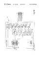
- FIG. 5COne embodiment of the n-current preamplifier 64 which reduces the DAC circuitry is shown in FIG. 5C wherein the individual DACs ( 90 0 - 90 N ) of FIG. 5B have been replaced by a global DAC 104 for generating a global write current setting 105 (coarse write current setting), and a plurality of local DACs ( 106 0 - 106 N ) for generating a plurality of local write current settings ( 108 0 - 108 N ) (fine write current settings).
- Register 110provides the global current-setting control signal to the global DAC 104
- registers 112provide the local current-setting control signals to the local DACs ( 106 0 - 106 N ).
- the global write current setting 105 output by the global DAC 104is added to the local write current settings ( 108 0 - 108 N ) output by the local DACs ( 106 0 - 106 N ) at adders ( 114 0 - 114 N ) to generate the analog write current settings ( 116 0 - 116 N ) for controlling the write currents ( 66 0 - 66 N ) output by the driver circuits ( 100 0 - 100 N ).
- the global DAC 104 and the local DACs ( 106 0 - 106 N )are all driven by a common current source 92 output by current reference 94 so that the global DAC 104 and local DACs ( 106 0 - 106 N ) track together variations in the current reference 92 .
- a calibration procedure(described below) is executed to determine the optimal values for the global current-setting control signal stored in register 110 , as well as the local current setting control signals stored in registers 112 .
- the global current-setting control signalcould be set to a minimum current-setting control signal corresponding to the head 4 that requires the least write current in the disk array, and then set the local current-setting control signals incrementally higher for the remaining heads.
- the global current-setting control signalcould be set to a maximum write current corresponding to the head 4 that requires the most write current in the disk array, and then set the local current-setting control signals incrementally lower for the remaining heads 4 . Accordingly, the adders ( 114 0 - 114 N ) of FIG.
- 5Care designed to either add or subtract the local current settings ( 108 0 - 108 N ) from the global current setting 105 to generate the analog write current settings ( 116 0 - 116 N ) for controlling the driver circuits ( 100 0 - 100 N ).
- the accuracy of the write currents ( 66 0 - 66 N ) for each head 4 in the disk arraydepends on the resolution and range of the local current-setting control signals, which depends on the number of bits used to represent the current-setting control signals. Typically, the resolution and range necessary to provide adequate performance is rather small so that only a few bits ( 1 , 2 or 3 ) are needed to represent the local current-setting control signals. Because the digital circuitry internal to the n-current preamplifier 64 (buses, registers, etc.) are typically 8-bits wide, it would be inefficient to provide a separate 8-bit register for each of the local current-setting control signals. Thus, to further reduce the implementation cost of the n-current preamplifier 64 of FIG.
- registers 112which are 8-bits wide, store multiple local current-setting control signals. For example, if two bits were used to represent each local current-setting control signal, then each 8-bit register 112 would store four 2-bit local setting control signals. For a disk drive comprising four heads 4 , the n-current preamplifier 64 would require one 8-bit register 110 to store the global current-setting control signal, and one 8-bit register 112 for storing the four 2-bit local current-setting control signals.
- FIG. 5 DAnother alternative embodiment for the n-current preamplifier 64 of the present invention which reduces the circuitry associated with implementing the DACs ( 90 0 - 90 N ) of FIG. 5B is shown in FIG. 5 D.
- This embodimentemploys a single register 118 and DAC 120 configuration, a plurality of sample-and-hold (S/H) circuits ( 122 0 - 122 N ), and a switch 124 for applying the analog write current setting 126 output by the DAC 120 to the appropriate S/H circuit 122 n .
- S/Hsample-and-hold
- the head select circuit 38sets switch 124 over line 128 to select the corresponding S/H circuit 122 n which samples the analog write current setting 126 output by the DAC 120 and supplies it to the corresponding driver circuit 100 n , the output of which is also enabled by the head select circuit 38 over line 40 .
- the appropriate write current ( 66 0 - 66 N ) for each head 4is set just prior to writing a servo sector 18 by performing the following steps: load the write current-setting control signal into register 118 for each head 4 ; program the head select circuit 38 to set switch 124 to select the appropriate S/H circuit 122 n to sample and hold the analog write current setting 126 at the output of the DAC 120 ; and once all of the write current settings 126 corresponding to each head have been sampled and are available at the outputs of the S/H circuits ( 122 0 - 122 N ), program the head select circuit 38 to enable the output of all the driver circuits ( 100 0 - 100 N ) to simultaneously write the servo sector 18 to all surfaces of the disks.
- the n-current preamplifier 64 of FIG. 5Dcould be implemented using a separate register 118 for each current-setting control signal which would avoid the latency in transferring the current-setting control signals from the disk controller 54 to register 118 in the n-current preamplifier 64 over the serial interface.
- the n-current preamplifier 64could be designed to continuously resample the analog write current setting 126 output by the DAC 120 to continuously refresh the analog write current settings ( 116 0 - 116 N ) at the outputs of the S/H circuits ( 122 0 - 122 N ) while writing the servo sector 18 to the recording surfaces, thereby compensating for loss in performance due to the S/H circuits ( 122 0 - 122 N ) bleeding.
- FIGS. 5B-5DAn example embodiment of the circuitry used to implement the driver circuits ( 100 0 - 100 N ) of FIGS. 5B-5D is shown in FIG. 6A, and an example embodiment of the circuitry used to generate the independent write currents ( 66 0 - 66 N ) output by the driver circuits ( 100 0 - 100 N ) is shown in FIG. 7 A and FIG. 7 B.
- the driver circuit 100 n shown in FIG. 6Ais a differential amplifier with the digital write data 42 , implemented as a differential signal, as the differential input.
- a “1” bit in the digital write data 42modulates a positive polarity in the differential input whereas a “0” bit modulates a negative polarity at the differential input.
- transistors 130 a , 132 a and 134 bare turned on while transistors 130 b , 132 b and 134 a are turned off causing current to flow from V CC at point B through transistor 134 b , through the write coil 136 , and through transistor 132 a to V EE .
- transistors 130 b , 132 b and 134 aare turned on while transistors 130 a , 132 a and 134 b are turned off causing current to flow from V CC at point A through transistor 134 a , through the write coil 136 , and through transistor 132 b to V EE .
- the polarity of the write current through the write coil 136is reversed as modulated by the polarity of the differential input signal (i.e., the digital write data 42 ).
- the magnitude of the write current 66 n flowing through the write coil 136 for each headis controlled by a write current source 138 n in each driver circuit 100 n , where each write current source 138 n is in turn controlled by the analog write current setting 116 n output by the DACs of FIG. 5B-5D.
- FIG. 6 BA typical configuration for a prior art write current source employed in the driver circuits ( 34 0 - 34 N ) of the prior art preamplifier of FIG. 4 is shown in FIG. 6 B.
- This circuitimplements a current mirror; the current 30 generated by the DAC 32 of FIG. 4 and flowing through transistor 140 is mirrored in a transistor ( 142 0 - 142 N ) of the write current source in each of the driver circuits ( 34 0 - 34 N ).
- the head select circuit 38 of FIG. 4controls the operation of a switch 144 in FIG.
- the head select circuit 38controls the switch 144 to connect the base terminal 146 of transistor 140 to all of the base terminals ( 148 0 - 148 N ) of transistors ( 142 0 - 142 N ) to simultaneously enable the output of all the driver circuits ( 34 0 - 34 N ).
- FIG. 7Ashows an example embodiment for the circuit used to generate the independent write currents ( 66 0 - 66 N ) output by the driver circuits ( 100 0 - 100 N ) of the n-current preamplifier 64 shown in FIG. 5 B.
- This circuitcomprises a separate, independent current mirror for generating the write current 66 n in each of the driver circuits ( 100 0 - 100 N ) of FIG. 6 A.
- the output of each DAC ( 90 0 - 90 N )generates a current ( 96 0 - 96 N ) in a respective transistor ( 150 0 - 150 N ) which is then mirrored in a companion transistor ( 152 0 - 152 N ) by connecting their base terminals as shown.
- the write current for each of the driver circuits ( 100 0 - 100 N )is set separately and independently according to the outputs of the DACs ( 90 0 - 90 N ).
- FIG. 7Bshows an example embodiment for the circuit used to generate the independent write currents ( 66 0 - 66 N ) output by the driver circuits ( 100 0 - 100 N ) of the n-current preamplifier 64 shown in FIG. 5 C.
- This circuitcomprises a global current mirror for generating the global (coarse) current setting for each of the driver circuits ( 100 0 - 100 N ), and a separate local current mirror for generating the local (fine) current settings for each of the driver circuits ( 100 0 - 100 N ).
- the head select circuit 38controls the switch 158 to connect the base terminal 162 of transistor 154 to the base terminal 160 n of the appropriate write current transistor ( 156 0 - 156 N ).
- the head select circuit 38controls the switch 158 to connect the base terminal 162 of transistor 154 to the base terminals ( 160 0 - 160 N ) of all of the write current transistors ( 156 0 - 156 N ).
- the local current settings for each driver circuit ( 100 0 - 100 N )is generated by a local current mirror driven by the output of one of the local DACs ( 106 0 - 106 N ).
- the local current setting for the first driver circuit 100 0is generated by the current mirror formed by local DAC 106 0 generating a current 108 0 in transistors 164 0 and mirrored in transistor 166 0 .
- the current flowing through transistors 166 0 and 156 0are added to generate the write current 66 0 for driver circuit 100 0 .
- a calibration procedureis preferably used for determining the appropriate current-setting control signals for providing the optimal write current ( 66 0 - 66 N ) for each head 4 in the disk array before bank servo writing the servo sectors to the disks 2 .
- the calibration procedurecan be executed by the controller 87 in the external servo track writer shown in FIG. 3 B. Alternatively, the calibration procedure can be executed by the disk controller 54 of FIG. 3 in a self-servowriting mode.
- the steps of the calibration procedureare performed for each head/surface combination, and it may optionally be carried out for different areas of each recording surface; for example, the appropriate current-setting control signal may be determined for each zone of the recording surface to compensate for variations in the magnetic characteristics from the inner to outer diameter tracks.
- the calibration procedureinvolves adjusting the current-setting control signal for a particular head 4 , providing the write current ( 66 0 - 66 N ) for writing a test pattern to the recording surface, reading the test pattern from the recording surface, and generating a quality metric indicative of a quality of the current-setting control signal and the associated write current ( 66 0 - 66 N ).
- These stepsare iterated for several different current-setting control signals, and the current-setting control signal that generates the best (optimal) quality metric is selected as the optimal current-setting control signal for producing the write current to write the servo sectors.
- the quality metricis preferably generated using discrete-time circuitry to facilitate adapting (programming) the calibration procedure to the various magnetic disks and heads found in the market.
- the read/write channel 58 of FIG. 3Cis preferably implemented using discrete-time circuitry to implement partial response/maximum likelihood (PRML) detection algorithms.
- PRMLpartial response/maximum likelihood
- a PRML read/write circuitcomprises a channel calibration circuit for calibrating the optimal write currents for servo writing.
- FIG. 3Cshows the read/write channel 58 generating a quality metric 74 that is supplied to the disk controller 54 which performs the calibration procedure when self-servowriting the recording surfaces.
- a write current calibration and bank servo write procedure 800illustrates calibrating the n-current preamplifier 64 of FIG. 5C which comprises a global write current-setting control signal and a local write current-setting control signal; however, those skilled in the art are capable of modifying the flow diagrams to conform to the implementation of the n-current preamplifiers shown in FIG. 5 B and FIG. 5 D.
- the flow diagramsillustrate the calibration procedure performed for each zone on each surface of the disks, but this is not a necessary aspect of the embodiment.
- a single write currentfor the entire recording surface, for example, an optimal write current measured at the center of the disk or an optimal write current computed from an average of several write currents measured at different locations on the recording surface (e.g., the average of write currents measured at the various zones).
- the first step 170 of the calibration procedure 800is to initialize a variable HEAD, which represents the current head being calibrated, to zero (the first head), and to initialize a variable ZONE, which represents the current zone on the recording surface, to zero (the first zone).
- a variable GLOBAL_CURwhich represents the global current-setting control signal stored in register 110 for the global DAC 104 of FIG. 5C, is set to a minimum;
- a variable LOCAL_CURwhich represents the local current setting control signal for a corresponding local current register 112 of FIG.
- a variable QUALITY METRICwhich represents the best quality metric measured for the current zone, is set to a minimum.
- the HEAD being calibratedis positioned over the current ZONE, and at step 176 a test pattern is written to the disk.
- the test patternis read from the disk, and at step 180 a quality metric is measured in response to the test pattern.
- An overwrite measurementis generated by:
- the overwrite measurement(quality metric) is then computed as the ratio of the energy in the low frequency signal component to the energy in the residual low frequency signal component:
- Quality Metricenergy-lowfreq/energy-lowfreq-residual.
- the overwrite measurementis a good indication of how well the write current ( 66 0 - 66 N ) saturates the recording surface, and therefore it is a good quality metric for use in calibrating the optimal write current ( 66 0 - 66 N ) for writing servo sectors.
- the optimal write current (and best quality metric)is the minimum write current that achieves a predetermined overwrite measurement (e.g., 35-40 db).
- the quality metric measured at step 180is compared to the previous best measured QUALITY METRIC and, if better, then at step 184 the current quality metric is saved along with the global write current-setting control signal GLOBAL_CUR and local write current-setting control signal LOCAL_CUR.
- the local write current-setting control signal LOCAL_CURis incremented and a new quality metric is measured. This procedure is repeated until the last local write current-setting control signal has been tried at step 188 , wherein at step 190 the global write current-setting control signal GLOBAL_CUR is incremented and the local write current-setting control signal LOCAL_CUR is reset to a minimum.
- the loopwill terminate as soon as the minimum write current ( 66 0 - 66 N ) is found that generates the desired overwrite measurement rather than test all combinations of global and local current-setting control signals.
- the flow diagram of FIG. 9Bis executed.
- the optimal global write current-setting control signal GLOBAL_CUR and local write current-setting control signal LOCAL_CUR saved at step 184 of FIG. 8Aare stored in memory. If at step 196 the last zone has not been reached, then the ZONE variable is incremented at step 198 and the flow diagram of FIG. 8A is re-executed for the next zone on the current recording surface. If at step 200 the last head has not been calibrated, then at step 202 the HEAD variable is incremented, the ZONE variable is reset to zero, and the calibration procedure 800 is re-executed for the next head.
- the optimal write current ( 66 0 - 66 N ) for each head and in each zoneare computed for the global write current-setting control signal and the local write current-setting control signals from the values stored in memory at step 194 .
- the global write current-setting control signalmay be set to the minimum write current ( 66 0 - 66 N ) calibrated for the disk array, and the local write current-setting control signals for the remaining heads set to an incremental offset added to the global write current-setting control signal.
- the bank servo write operationis performed to simultaneously write the embedded servo sectors to all of the recording surfaces.
- the ZONE variableis reset to zero to begin bank writing the recording surfaces at the first zone.
- the global and local write current-setting control signals for each headare loaded into the n-current preamplifier 64 and at step 210 the bank servo write operation writes the embedded servo sectors to the tracks in the current zone on all the recording surfaces.
- the ZONE variableis then incremented at step 212 , the global and local write current-setting control signals for the next zone are loaded into the n-current preamplifier 64 at step 208 , and the bank servo write operation at step 210 writes the embedded servo sectors to the tracks in the next zone on all of the recording surfaces. This process is reiterated until the last zone on all the disks has been servo written (i.e., the last ZONE is reached at step 214 in FIG. 8B) wherein the bank servo write procedure terminates.
Landscapes
- Engineering & Computer Science (AREA)
- Signal Processing (AREA)
- Digital Magnetic Recording (AREA)
Abstract
Description
Claims (14)
Priority Applications (1)
| Application Number | Priority Date | Filing Date | Title |
|---|---|---|---|
| US09/342,670US6310740B1 (en) | 1999-06-29 | 1999-06-29 | Disk drive including N-current preamplifier for generating N-independently controlled write currents |
Applications Claiming Priority (1)
| Application Number | Priority Date | Filing Date | Title |
|---|---|---|---|
| US09/342,670US6310740B1 (en) | 1999-06-29 | 1999-06-29 | Disk drive including N-current preamplifier for generating N-independently controlled write currents |
Publications (1)
| Publication Number | Publication Date |
|---|---|
| US6310740B1true US6310740B1 (en) | 2001-10-30 |
Family
ID=23342783
Family Applications (1)
| Application Number | Title | Priority Date | Filing Date |
|---|---|---|---|
| US09/342,670Expired - LifetimeUS6310740B1 (en) | 1999-06-29 | 1999-06-29 | Disk drive including N-current preamplifier for generating N-independently controlled write currents |
Country Status (1)
| Country | Link |
|---|---|
| US (1) | US6310740B1 (en) |
Cited By (170)
| Publication number | Priority date | Publication date | Assignee | Title |
|---|---|---|---|---|
| US6525892B1 (en)* | 2000-01-28 | 2003-02-25 | Western Digital Technologies, Inc. | Method of calibrating a write current-setting for servo writing a disk drive |
| US6587805B2 (en)* | 2000-02-25 | 2003-07-01 | Seagate Technology Llc | Testing a write transducer as a reader |
| US6717759B1 (en)* | 2001-02-16 | 2004-04-06 | Maxtor Corporation | Hindering PTP in a hard disk |
| US20040085666A1 (en)* | 2002-10-30 | 2004-05-06 | International Business Machines Corporation | Method and system to measure the write current of a current mode write driver in a direct way |
| US20040105315A1 (en)* | 2002-12-02 | 2004-06-03 | Tretter Larry Leeroy | Measurement of the write current of a current mode write driver while engaged in the writing process |
| US6757800B1 (en)* | 1995-07-31 | 2004-06-29 | Lexar Media, Inc. | Increasing the memory performance of flash memory devices by writing sectors simultaneously to multiple flash memory devices |
| US20040150903A1 (en)* | 2003-01-31 | 2004-08-05 | Hitachi Global Storage Technologies | Adaptive track count determination for a self-servowritten disk drive |
| US6798610B1 (en)* | 2000-04-24 | 2004-09-28 | Maxtor Corporation | Disk drive with self servo writing capability |
| US6894861B1 (en)* | 2001-09-28 | 2005-05-17 | Western Digital Technologies, Inc. | Method for reducing written-in runout during servo track writing of a disk drive |
| US20050243661A1 (en)* | 2004-05-03 | 2005-11-03 | Tormasi Walter A | Striping data simultaneously across multiple platter surfaces |
| US20060001994A1 (en)* | 2004-06-30 | 2006-01-05 | Hitachi Global Technologies Netherlands B.V. | Method, apparatus and program storage device for dynamically adjusting the write current in each head to compensate for variation in disk drive and environmental parameters |
| US20060114587A1 (en)* | 2004-11-30 | 2006-06-01 | Kalahasthi Indukumar C | Method for precompensation/write-current latching to improve error rate |
| US20060256624A1 (en)* | 2003-06-24 | 2006-11-16 | Micron Technology, Inc. | Erase block data splitting |
| US7388728B1 (en)* | 2006-09-22 | 2008-06-17 | Western Digital Technologies, Inc. | System and method for writing servo sectors in a perpendicular media recording environment |
| US20080198491A1 (en)* | 2007-02-16 | 2008-08-21 | Samsung Electronics Co., Ltd. | Method of setting write factor in hard disk drive and hard disk drive using the same |
| US7466509B1 (en)* | 2006-09-22 | 2008-12-16 | Western Digital Technologies, Inc. | Disk drive operable with first and second servo patterns in a perpendicular media recording environment |
| US20090128947A1 (en)* | 2007-11-15 | 2009-05-21 | Western Digital (Fremont), Llc | Disk drive determining operating fly height by detecting head disk contact from disk rotation time |
| US20090195936A1 (en)* | 2008-02-04 | 2009-08-06 | Western Digital Technologies, Inc. | Disk drive servoing off of first head while determining fly height for second head |
| US7656603B1 (en) | 2007-11-30 | 2010-02-02 | Western Digital Technologies, Inc. | Pre-programming of a preamplifier in a disk drive to improve servo-writing characteristics |
| US7675707B1 (en) | 2008-11-21 | 2010-03-09 | Western Digital Technologies, Inc. | Disk drive employing repeatable disturbance compensation for fly height control |
| US7839595B1 (en) | 2008-01-25 | 2010-11-23 | Western Digital Technologies, Inc. | Feed forward compensation for fly height control in a disk drive |
| US7916420B1 (en) | 2010-05-14 | 2011-03-29 | Western Digital Technologies, Inc. | Disk drive employing comb filter for repeatable fly height compensation |
| US20110226729A1 (en)* | 2007-11-01 | 2011-09-22 | Western Digital Technologies, Inc. | Method of manufacturing a double sided flex circuit for a disk drive wherein a first side lead provides an etching mask for a second side lead |
| US8059357B1 (en) | 2010-03-18 | 2011-11-15 | Western Digital Technologies, Inc. | Disk drive adjusting fly height when calibrating head/disk contact |
| US8169726B2 (en)* | 2010-07-19 | 2012-05-01 | Lsi Corporation | Disk file preamplifier frequency-response and time delay compensation |
| US20120262812A1 (en)* | 2011-02-11 | 2012-10-18 | Xyratex Technology Limited | Test apparatus and method of testing with a test apparatus |
| US8300338B1 (en) | 2010-09-30 | 2012-10-30 | Western Digital Technologies, Inc. | Disk drive correlating different fly height measurements to verify disk warpage |
| US8320069B1 (en) | 2010-03-18 | 2012-11-27 | Western Digital Technologies, Inc. | Disk drive detecting positive correlation in fly height measurements |
| US8482873B1 (en) | 2008-02-18 | 2013-07-09 | Western Digital Technologies, Inc. | Disk drive employing pulse width modulation of head control signal |
| US8879188B1 (en) | 2010-08-23 | 2014-11-04 | Western Digital Technologies, Inc. | Disk drive employing fly height calibration tracks to account for magnetic entropy and thermal decay |
| US8891193B1 (en) | 2013-05-09 | 2014-11-18 | Western Digital Technologies, Inc. | Disk drive calibrating threshold and gain of touchdown sensor |
| US8891341B1 (en) | 2013-03-11 | 2014-11-18 | Western Digital Technologies, Inc. | Energy assisted magnetic recording disk drive using modulated laser light |
| US8902527B1 (en) | 2010-03-22 | 2014-12-02 | Western Digital Technologies, Inc. | Systems and methods for improving sequential data rate performance using sorted data zones |
| US8902529B1 (en) | 2012-11-20 | 2014-12-02 | Western Digital Technologies, Inc. | Dual frequency crystal oscillator |
| US8909889B1 (en) | 2011-10-10 | 2014-12-09 | Western Digital Technologies, Inc. | Method and apparatus for servicing host commands by a disk drive |
| US8908311B1 (en) | 2014-01-27 | 2014-12-09 | Western Digital Technologies, Inc. | Data storage device writing a multi-sector codeword in segments over multiple disk revolutions |
| US8914625B1 (en) | 2009-07-31 | 2014-12-16 | Western Digital Technologies, Inc. | Automatically configuring a web browser file when booting an operating system from a data storage device |
| US8922939B1 (en) | 2013-04-02 | 2014-12-30 | Western Digital Technologies, Inc. | Disk drive generating feed-forward fly height control based on temperature sensitive fly height sensor |
| US8934192B1 (en) | 2008-11-24 | 2015-01-13 | Western Digital Technologies, Inc. | Disk drive determining operating fly height by detecting head disk contact from read signal amplitude variance |
| US8937782B1 (en) | 2012-05-07 | 2015-01-20 | Western Digital Technologies, Inc. | Hard disk drive assembly including a NVSM to store configuration data for controlling disk drive operations |
| US8941941B1 (en) | 2013-02-28 | 2015-01-27 | Western Digital Technologies, Inc. | Disk drive calibrating touchdown sensor |
| US20150029613A1 (en)* | 2012-07-16 | 2015-01-29 | Seagate Technology Llc | Pin-efficient reader bias enable control |
| US8947812B1 (en) | 2014-03-27 | 2015-02-03 | Western Digital Technologies, Inc. | Data storage device comprising equalizer filter and inter-track interference filter |
| US8949521B1 (en) | 2013-04-10 | 2015-02-03 | Western Digital Technologies, Inc. | Actuator prepositioning for disk drive |
| US8954664B1 (en) | 2010-10-01 | 2015-02-10 | Western Digital Technologies, Inc. | Writing metadata files on a disk |
| US8953269B1 (en) | 2014-07-18 | 2015-02-10 | Western Digital Technologies, Inc. | Management of data objects in a data object zone |
| US8953277B1 (en) | 2014-06-16 | 2015-02-10 | Western Digital Technologies, Inc. | Data storage device writing tracks on a disk with equal spacing |
| US8958167B1 (en) | 2013-12-23 | 2015-02-17 | Western Digital Technologies, Inc. | Detection of disk surface irregularities in data storage devices |
| US8959281B1 (en) | 2012-11-09 | 2015-02-17 | Western Digital Technologies, Inc. | Data management for a storage device |
| US8970978B1 (en) | 2012-10-22 | 2015-03-03 | Western Digital Technologies, Inc. | Disk drive detecting head touchdown by applying DC+AC control signal to fly height actuator |
| US8976633B1 (en) | 2014-04-15 | 2015-03-10 | Western Digital Technologies, Inc. | Data storage device calibrating fly height actuator based on laser power for heat assisted magnetic recording |
| US8990493B1 (en) | 2011-06-30 | 2015-03-24 | Western Digital Technologies, Inc. | Method and apparatus for performing force unit access writes on a disk |
| US8988810B1 (en) | 2014-04-16 | 2015-03-24 | Western Digital Technologies, Inc. | Track measurement for data storage device |
| US8988809B1 (en) | 2014-02-18 | 2015-03-24 | Western Digital (Fremont), Llc | Disk recording device for writing a radially coherent reference band by measuring relative timing offsets of reference bursts |
| US8996839B1 (en) | 2012-01-23 | 2015-03-31 | Western Digital Technologies, Inc. | Data storage device aligning partition to boundary of sector when partition offset correlates with offset of write commands |
| US9001453B1 (en) | 2014-07-18 | 2015-04-07 | Western Digital Technologies, Inc. | Data storage device calibrating fly height actuator based on read mode touchdown resistance of touchdown sensor |
| US9009358B1 (en) | 2008-09-23 | 2015-04-14 | Western Digital Technologies, Inc. | Configuring a data storage device with a parameter file interlocked with configuration code |
| US9013821B1 (en) | 2014-06-10 | 2015-04-21 | Western Digital Technologies, Inc. | Data storage device employing one-dimensional and two-dimensional channels |
| US9013818B1 (en) | 2013-12-06 | 2015-04-21 | Western Digital Technologies, Inc. | Disk drive measuring reader/writer gap by measuring fractional clock cycle over disk radius |
| US9021410B1 (en) | 2013-12-10 | 2015-04-28 | Western Technologies, Inc. | Electronic system with multi-cycle simulation coverage mechanism and method of operation thereof |
| US9025421B1 (en) | 2014-10-08 | 2015-05-05 | Western Digital Technologies, Inc. | Data storage device adjusting laser input power to compensate for temperature variations |
| US9025270B1 (en) | 2013-09-17 | 2015-05-05 | Western Digital Technologies, Inc. | Electronic system with current conservation mechanism and method of operation thereof |
| US9025267B1 (en) | 2014-06-09 | 2015-05-05 | Western Digital Technologies, Inc. | Data storage device using branch metric from adjacent track to compensate for inter-track interference |
| US9047917B1 (en) | 2013-11-26 | 2015-06-02 | Western Digital Technologies, Inc. | Disk drive slider with sense amplifier for coupling to a preamp through a supply/bias line and a read signal line |
| US9049471B2 (en) | 2001-10-17 | 2015-06-02 | Keen Personal Media, Inc. | Personal video recorder for inserting a stored advertisement into a displayed broadcast stream |
| US9053730B1 (en) | 2012-05-11 | 2015-06-09 | Western Digital Technologies, Inc. | Disk drive comprising extended range head proximity sensor |
| US9053749B1 (en) | 2013-03-15 | 2015-06-09 | Western Digital Technologies, Inc. | Disk drive comprising a per-drive and per-head fly height filter |
| US9064542B1 (en) | 2013-04-08 | 2015-06-23 | Western Digital Technologies, Inc. | Scheduled load of heads to reduce lubricant migration on pole tip and decrease time to ready |
| US9063838B1 (en) | 2012-01-23 | 2015-06-23 | Western Digital Technologies, Inc. | Data storage device shifting data chunks of alignment zone relative to sector boundaries |
| US9064525B2 (en) | 2013-11-26 | 2015-06-23 | Western Digital Technologies, Inc. | Disk drive comprising laser transmission line optimized for heat assisted magnetic recording |
| US9064504B1 (en) | 2014-01-29 | 2015-06-23 | Western Digital Technologies, Inc. | Electronic system with media recovery mechanism and method of operation thereof |
| US9070406B1 (en) | 2014-03-10 | 2015-06-30 | Western Digital Technologies, Inc. | Disk drive configuring one-dimensional and two-dimensional recording areas based on read element spacing |
| US9074941B1 (en) | 2013-03-14 | 2015-07-07 | Western Digital Technologies, Inc. | Systems and methods for measuring ambient and laser temperature in heat assisted magnetic recording |
| US9075714B1 (en) | 2014-05-13 | 2015-07-07 | Western Digital Technologies, Inc. | Electronic system with data management mechanism and method of operation thereof |
| US9076474B1 (en) | 2014-12-23 | 2015-07-07 | Western Digital Technologies, Inc. | Data storage device attenuating thermal decay effect on fly height measurement |
| US9082458B1 (en) | 2014-03-10 | 2015-07-14 | Western Digital Technologies, Inc. | Data storage device balancing and maximizing quality metric when configuring arial density of each disk surface |
| US9099144B1 (en) | 2013-10-11 | 2015-08-04 | Western Digital Technologies, Inc. | Disk drive evaluating laser performance for heat assisted magnetic recording |
| US9099134B1 (en) | 2015-01-27 | 2015-08-04 | Western Digital Technologies, Inc. | Data storage device employing multiple jog profiles for a butterfly written disk surface |
| US9099103B1 (en) | 2014-10-21 | 2015-08-04 | Western Digital Technologies, Inc. | Heat assisted magnetic recording withinterlaced high-power heated and low-power heated tracks |
| US9117463B1 (en) | 2014-06-23 | 2015-08-25 | Western Digital Technologies, Inc. | Data storage device erasing multiple adjacent data tracks to recover from inter-track interference |
| US9117489B1 (en) | 2014-02-18 | 2015-08-25 | Western Digital Technologies, Inc. | Data storage device screening heads by verifying defects after defect scan |
| US9117479B1 (en) | 2014-09-24 | 2015-08-25 | Western Digital Technologies, Inc. | Data storage device calibrating laser write power for heat assisted magnetic recording |
| US9123370B1 (en) | 2014-04-15 | 2015-09-01 | Western Digital Technologies, Inc. | Data storage device calibrating fly height actuator based on laser power for heat assisted magnetic recording |
| US9123382B1 (en) | 2014-10-28 | 2015-09-01 | Western Digital Technologies, Inc. | Non-volatile caching for sequence of data |
| US9129628B1 (en) | 2014-10-23 | 2015-09-08 | Western Digital Technologies, Inc. | Data management for data storage device with different track density regions |
| US9128820B1 (en) | 2012-06-18 | 2015-09-08 | Western Digital Technologies, Inc. | File management among different zones of storage media |
| US9135205B1 (en) | 2013-05-01 | 2015-09-15 | Western Digital Technologies, Inc. | Data storage assembly for archive cold storage |
| US9153287B1 (en) | 2013-05-13 | 2015-10-06 | Western Digital Technologies, Inc. | Data access for shingled magnetic recording media |
| US9153266B1 (en) | 2014-09-11 | 2015-10-06 | Western Digital Technologies, Inc. | Data storage device measuring laser protrusion fly height profile |
| US9158722B1 (en) | 2011-11-02 | 2015-10-13 | Western Digital Technologies, Inc. | Data storage device to communicate with a host in a SATA or a USB mode |
| US9164694B1 (en) | 2013-06-19 | 2015-10-20 | Western Digital Technologies, Inc. | Data storage device detecting read-before-write conditions and returning configurable return data |
| US9171575B1 (en) | 2014-06-23 | 2015-10-27 | Western Digital Technologies, Inc. | Data storage device detecting media defects by writing opposite polarity test pattern |
| US9183864B1 (en) | 2013-06-13 | 2015-11-10 | Western Digital Technologies, Inc. | Disk drive adjusting closed-loop fly height target based on change in open-loop fly height control signal |
| US9183877B1 (en) | 2015-03-20 | 2015-11-10 | Western Digital Technologies, Inc. | Data storage device comprising two-dimensional data dependent noise whitening filters for two-dimensional recording |
| US9189392B1 (en) | 2011-06-30 | 2015-11-17 | Western Digital Technologies, Inc. | Opportunistic defragmentation during garbage collection |
| US9196302B1 (en) | 2015-03-18 | 2015-11-24 | Western Digital Technologies, Inc. | Electronic system with media maintenance mechanism and method of operation thereof |
| US9214186B1 (en) | 2015-03-23 | 2015-12-15 | Western Digital Technologies, Inc. | Data storage device measuring radial offset between read element and write element |
| US9213493B1 (en) | 2011-12-16 | 2015-12-15 | Western Digital Technologies, Inc. | Sorted serpentine mapping for storage drives |
| US9230585B1 (en) | 2014-01-31 | 2016-01-05 | Western Digital Technologies, Inc. | Per wedge preheat DFH to improve data storage device performance |
| US9230605B1 (en) | 2014-12-01 | 2016-01-05 | Western Digital Technologies, Inc. | Data storage device maximizing areal density based on a target quality metric |
| US9236086B1 (en) | 2014-10-15 | 2016-01-12 | Western Digital Technologies, Inc. | Methods for reducing operational latency of data storage systems |
| US9245556B2 (en) | 2014-03-10 | 2016-01-26 | Western Digital Technologies, Inc. | Disk drive employing multiple read elements to increase radial band for two-dimensional magnetic recording |
| US9245558B1 (en) | 2014-05-09 | 2016-01-26 | Western Digital Technologies, Inc. | Electronic system with data management mechanism and method of operation thereof |
| US9251856B1 (en) | 2014-05-30 | 2016-02-02 | Western Digial Technologies, Inc. | Read failover method and apparatus for a data storage system |
| US9251844B1 (en) | 2014-06-02 | 2016-02-02 | Western Digital Technologies, Inc. | Waterfall method and apparatus for a data storage device read system |
| US9257145B1 (en) | 2013-11-27 | 2016-02-09 | Western Digital Technologies, Inc. | Disk drive measuring down-track spacing of read sensors |
| US9257146B1 (en) | 2014-02-11 | 2016-02-09 | Western Digital Technologies, Inc. | Data storage device comprising sequence detector compensating for inter-track interference |
| US9257143B1 (en) | 2014-12-23 | 2016-02-09 | Western Digital Technologies, Inc. | Precautionary measures for data storage device environmental conditions |
| US9263088B2 (en) | 2014-03-21 | 2016-02-16 | Western Digital Technologies, Inc. | Data management for a data storage device using a last resort zone |
| US9268649B1 (en) | 2011-06-23 | 2016-02-23 | Western Digital Technologies, Inc. | Disk drive with recent write streams list for data refresh determination |
| US9269393B1 (en) | 2014-12-08 | 2016-02-23 | Western Digital Technologies, Inc. | Electronic system with data refresh mechanism and method of operation thereof |
| US9268499B1 (en) | 2010-08-13 | 2016-02-23 | Western Digital Technologies, Inc. | Hybrid drive migrating high workload data from disk to non-volatile semiconductor memory |
| US9281009B1 (en) | 2014-12-18 | 2016-03-08 | Western Digital Technologies, Inc. | Data storage device employing variable size interleave written track segments |
| US9311939B1 (en) | 2014-12-23 | 2016-04-12 | Western Digital Technologies, Inc. | Write-through media caching |
| US9318137B1 (en) | 2015-03-13 | 2016-04-19 | Western Digital Technologies, Inc. | Data storage device executing retry operation by buffering signal samples at different radial offsets |
| US9330715B1 (en) | 2010-03-22 | 2016-05-03 | Western Digital Technologies, Inc. | Mapping of shingled magnetic recording media |
| US9355666B1 (en) | 2013-09-30 | 2016-05-31 | Western Digital Technologies, Inc. | Disk drive measuring stroke difference between heads by detecting a difference between ramp contact |
| US9361938B1 (en) | 2015-04-16 | 2016-06-07 | Western Digital Technologies, Inc. | Disk defect management for a data storage device |
| US9368131B1 (en) | 2015-04-03 | 2016-06-14 | Western Digital (Fremont), Llc | Data storage device employing mirrored cross-track profiles for top and bottom disk surfaces |
| US9368132B1 (en) | 2015-09-04 | 2016-06-14 | Western Digital Technologies, Inc. | Data storage device employing differential write data signal and differential write pattern signal |
| US9383923B1 (en) | 2012-10-18 | 2016-07-05 | Western Digital Technologies, Inc. | Write pointer management for a disk drive |
| US9401165B1 (en) | 2014-05-05 | 2016-07-26 | Western Digital Technologies, Inc. | Method and system to monitor magnetic head loading and unloading stability for a data storage system |
| US9417628B2 (en) | 2013-03-13 | 2016-08-16 | Western Digital Technologies, Inc. | Production failure analysis system |
| US9424864B2 (en) | 2014-07-02 | 2016-08-23 | Western Digital Technologies, Inc. | Data management for a data storage device with zone relocation |
| US9437242B1 (en) | 2015-09-14 | 2016-09-06 | Western Digital Technologies, Inc. | Data storage device employing different frequency preambles in adjacent data tracks |
| US9466318B2 (en) | 2014-12-24 | 2016-10-11 | Western Digital Technologies, Inc. | Allowing fast data zone switches on data storage devices |
| US9466321B1 (en) | 2015-06-05 | 2016-10-11 | Western Digital Technologies, Inc. | Angular position tracking of data accesses to mitigate risk of data loss |
| US9472219B1 (en) | 2015-05-01 | 2016-10-18 | Western Digital Technologies, Inc. | Data storage device calibrating parameter for heat assisted magnetic recording |
| US9501393B2 (en) | 2014-01-27 | 2016-11-22 | Western Digital Technologies, Inc. | Data storage system garbage collection based on at least one attribute |
| US9502068B1 (en) | 2015-04-08 | 2016-11-22 | Western Digital Technologies, Inc. | Data storage device updating laser power during non-write mode for heat assisted magnetic recording |
| US9588898B1 (en) | 2015-06-02 | 2017-03-07 | Western Digital Technologies, Inc. | Fullness control for media-based cache operating in a steady state |
| US9600205B1 (en) | 2014-09-22 | 2017-03-21 | Western Digital Technologies, Inc. | Power aware power safe write buffer |
| US9632711B1 (en) | 2014-04-07 | 2017-04-25 | Western Digital Technologies, Inc. | Processing flush requests by utilizing storage system write notifications |
| US9639287B1 (en) | 2015-06-29 | 2017-05-02 | Western Digital Technologies, Inc. | Write command reporting |
| US9645752B1 (en) | 2014-04-07 | 2017-05-09 | Western Digital Technologies, Inc. | Identification of data committed to non-volatile memory by use of notification commands |
| US9672107B1 (en) | 2015-02-11 | 2017-06-06 | Western Digital Technologies, Inc. | Data protection for a data storage device |
| US9715887B2 (en)* | 2015-12-28 | 2017-07-25 | Avago Technologies General Ip (Singapore) Pte. Ltd. | Magnetic recording system using pattern dependent writer having register pages for storing write currents |
| US9747928B1 (en) | 2014-09-25 | 2017-08-29 | Western Digital Technologies, Inc. | Data storage device modifying write operation when a laser mode hop is detected |
| US9761273B1 (en) | 2015-11-03 | 2017-09-12 | Western Digital Technologies, Inc. | Data storage device encoding and interleaving codewords to improve trellis sequence detection |
| US9842617B1 (en) | 2015-06-29 | 2017-12-12 | Western Digital Technologies, Inc. | Electronic system with head management mechanism and method of operation thereof |
| US9842622B1 (en) | 2014-12-23 | 2017-12-12 | Western Digital Technologies, Inc. | Data storage device having improved read failure tolerance |
| US9864529B1 (en) | 2014-01-27 | 2018-01-09 | Western Digital Technologies, Inc. | Host compatibility for host managed storage media |
| US9870281B1 (en) | 2015-03-20 | 2018-01-16 | Western Digital Technologies, Inc. | Power loss mitigation for data storage device |
| US9875055B1 (en) | 2014-08-04 | 2018-01-23 | Western Digital Technologies, Inc. | Check-pointing of metadata |
| US9916616B2 (en) | 2014-03-31 | 2018-03-13 | Western Digital Technologies, Inc. | Inventory management system using incremental capacity formats |
| US9933955B1 (en) | 2015-03-05 | 2018-04-03 | Western Digital Technologies, Inc. | Power safe write buffer for data storage device |
| US9952950B1 (en) | 2014-09-08 | 2018-04-24 | Western Digital Technologies, Inc. | Data management in RAID environment |
| US9959052B1 (en) | 2015-09-17 | 2018-05-01 | Western Digital Technologies, Inc. | Media based cache for data storage device |
| US9962050B2 (en) | 2016-08-29 | 2018-05-08 | Omachron Intellectual Property Inc. | Surface cleaning apparatus |
| US10056920B1 (en) | 2015-11-03 | 2018-08-21 | Western Digital Technologies, Inc. | Data storage device encoding and interleaving codewords to improve trellis sequence detection |
| US10063257B1 (en) | 2015-11-03 | 2018-08-28 | Western Digital Technologies, Inc. | Data storage device encoding and interleaving codewords to improve trellis sequence detection |
| US10136779B2 (en) | 2016-08-29 | 2018-11-27 | Omachron Intellectual Property Inc. | Surface cleaning apparatus |
| US10136780B2 (en) | 2016-08-29 | 2018-11-27 | Omachron Intellectual Property Inc. | Surface cleaning apparatus |
| US10261832B2 (en) | 2015-12-02 | 2019-04-16 | At&T Mobility Ii Llc | Sorting apparatus |
| US10282096B1 (en) | 2014-12-17 | 2019-05-07 | Western Digital Technologies, Inc. | Identification of data with predetermined data pattern |
| US10282371B1 (en) | 2014-12-02 | 2019-05-07 | Western Digital Technologies, Inc. | Object storage device with probabilistic data structure |
| US10296612B2 (en) | 2015-09-29 | 2019-05-21 | At&T Mobility Ii Llc | Sorting system |
| US10292550B2 (en) | 2016-08-29 | 2019-05-21 | Omachron Intellectual Property Inc. | Surface cleaning apparatus |
| US10321794B2 (en) | 2016-08-29 | 2019-06-18 | Omachron Intellectual Property Inc. | Surface cleaning apparatus |
| US10365836B1 (en) | 2015-01-27 | 2019-07-30 | Western Digital Technologies, Inc. | Electronic system with declustered data protection by parity based on reliability and method of operation thereof |
| US10405711B2 (en) | 2016-08-29 | 2019-09-10 | Omachron Intellectual Property Inc. | Surface cleaning apparatus |
| US10413141B2 (en) | 2016-08-29 | 2019-09-17 | Omachron Intellectual Property Inc. | Surface cleaning apparatus |
| US10416959B2 (en)* | 2015-10-27 | 2019-09-17 | At&T Mobility Ii Llc | Analog sorter |
| US10433689B2 (en) | 2016-08-29 | 2019-10-08 | Omachron Intellectual Property Inc. | Surface cleaning apparatus |
| US10441125B2 (en) | 2016-08-29 | 2019-10-15 | Omachron Intellectual Property Inc. | Surface cleaning apparatus |
| US10441124B2 (en) | 2016-08-29 | 2019-10-15 | Omachron Intellectual Property Inc. | Surface cleaning apparatus |
| US10496370B2 (en) | 2015-12-02 | 2019-12-03 | At&T Intellectual Property I, L.P. | Adaptive alphanumeric sorting apparatus |
| US10504553B1 (en) | 2019-03-20 | 2019-12-10 | Western Digital Technologies, Inc. | Data storage device transmitting delta servo control value over serial interface |
| US10729295B2 (en) | 2016-08-29 | 2020-08-04 | Omachron Intellectual Property Inc. | Surface cleaning apparatus |
| US11478117B2 (en) | 2016-08-29 | 2022-10-25 | Omachron Intellectual Property Inc. | Surface cleaning apparatus |
Citations (16)
| Publication number | Priority date | Publication date | Assignee | Title |
|---|---|---|---|---|
| US4414589A (en) | 1981-12-14 | 1983-11-08 | Northern Telecom Inc. | Embedded servo track following system and method for writing servo tracks |
| US4669004A (en) | 1986-02-27 | 1987-05-26 | Quantum Corporation | High capacity disk file with embedded sector servo |
| US5339204A (en) | 1991-12-12 | 1994-08-16 | International Business Machines Corporation | System and method for servowriting a magnetic disk drive |
| US5448429A (en) | 1992-11-10 | 1995-09-05 | Cribbs; Daniel F. | Self-servowriting disk drive and method |
| US5465182A (en) | 1992-05-06 | 1995-11-07 | Fujitsu Limited | Recording method of servo information |
| US5488518A (en) | 1994-08-15 | 1996-01-30 | Vtc Inc. | Programmable pre-amplifier using a serial shift register to output a plurality of control signals |
| US5687036A (en)* | 1995-09-29 | 1997-11-11 | Seagate Technology, Inc. | Selection of optimum write current in a disc drive to minimize the occurrence of repeatable read errors |
| US5726821A (en) | 1995-12-22 | 1998-03-10 | Western Digital Corporation | Programmable preamplifier unit with serial interface for disk data storage device using MR heads |
| US5784296A (en) | 1996-04-30 | 1998-07-21 | Quantum Corporation | Method and apparatus for spectral analysis in a disk recording system |
| US5790331A (en)* | 1995-08-11 | 1998-08-04 | Mitel Semiconductor Americas Inc. | Current control circuit and method for programmable read write preamplifier |
| US5793554A (en) | 1996-07-09 | 1998-08-11 | International Business Machines Corporation | Self-servowriting system with dynamic error propagation reduction |
| US5796542A (en) | 1996-02-28 | 1998-08-18 | Western Digital Corporation | Servo-track writer system having a plurality of engaging pins co-axially rotated with head actuator pivot axes |
| US5875064A (en) | 1996-07-09 | 1999-02-23 | International Business Machines Corporation | Method and system for accurate self-servowriting with normalization in a disk drive |
| US5880901A (en) | 1996-01-02 | 1999-03-09 | International Business Machines Corporation | Method and apparatus for positioning a magnetoresistive head |
| US5896239A (en)* | 1992-12-18 | 1999-04-20 | Fujitsu Limited | Magnetic disk writing method and a magnetic disk apparatus |
| US6101053A (en)* | 1997-05-29 | 2000-08-08 | Fujitsu Limited | Write condition setting method and disk unit |
- 1999
- 1999-06-29USUS09/342,670patent/US6310740B1/ennot_activeExpired - Lifetime
Patent Citations (16)
| Publication number | Priority date | Publication date | Assignee | Title |
|---|---|---|---|---|
| US4414589A (en) | 1981-12-14 | 1983-11-08 | Northern Telecom Inc. | Embedded servo track following system and method for writing servo tracks |
| US4669004A (en) | 1986-02-27 | 1987-05-26 | Quantum Corporation | High capacity disk file with embedded sector servo |
| US5339204A (en) | 1991-12-12 | 1994-08-16 | International Business Machines Corporation | System and method for servowriting a magnetic disk drive |
| US5465182A (en) | 1992-05-06 | 1995-11-07 | Fujitsu Limited | Recording method of servo information |
| US5448429A (en) | 1992-11-10 | 1995-09-05 | Cribbs; Daniel F. | Self-servowriting disk drive and method |
| US5896239A (en)* | 1992-12-18 | 1999-04-20 | Fujitsu Limited | Magnetic disk writing method and a magnetic disk apparatus |
| US5488518A (en) | 1994-08-15 | 1996-01-30 | Vtc Inc. | Programmable pre-amplifier using a serial shift register to output a plurality of control signals |
| US5790331A (en)* | 1995-08-11 | 1998-08-04 | Mitel Semiconductor Americas Inc. | Current control circuit and method for programmable read write preamplifier |
| US5687036A (en)* | 1995-09-29 | 1997-11-11 | Seagate Technology, Inc. | Selection of optimum write current in a disc drive to minimize the occurrence of repeatable read errors |
| US5726821A (en) | 1995-12-22 | 1998-03-10 | Western Digital Corporation | Programmable preamplifier unit with serial interface for disk data storage device using MR heads |
| US5880901A (en) | 1996-01-02 | 1999-03-09 | International Business Machines Corporation | Method and apparatus for positioning a magnetoresistive head |
| US5796542A (en) | 1996-02-28 | 1998-08-18 | Western Digital Corporation | Servo-track writer system having a plurality of engaging pins co-axially rotated with head actuator pivot axes |
| US5784296A (en) | 1996-04-30 | 1998-07-21 | Quantum Corporation | Method and apparatus for spectral analysis in a disk recording system |
| US5875064A (en) | 1996-07-09 | 1999-02-23 | International Business Machines Corporation | Method and system for accurate self-servowriting with normalization in a disk drive |
| US5793554A (en) | 1996-07-09 | 1998-08-11 | International Business Machines Corporation | Self-servowriting system with dynamic error propagation reduction |
| US6101053A (en)* | 1997-05-29 | 2000-08-08 | Fujitsu Limited | Write condition setting method and disk unit |
Cited By (200)
| Publication number | Priority date | Publication date | Assignee | Title |
|---|---|---|---|---|
| US6757800B1 (en)* | 1995-07-31 | 2004-06-29 | Lexar Media, Inc. | Increasing the memory performance of flash memory devices by writing sectors simultaneously to multiple flash memory devices |
| US6525892B1 (en)* | 2000-01-28 | 2003-02-25 | Western Digital Technologies, Inc. | Method of calibrating a write current-setting for servo writing a disk drive |
| US6587805B2 (en)* | 2000-02-25 | 2003-07-01 | Seagate Technology Llc | Testing a write transducer as a reader |
| US6798610B1 (en)* | 2000-04-24 | 2004-09-28 | Maxtor Corporation | Disk drive with self servo writing capability |
| US6717759B1 (en)* | 2001-02-16 | 2004-04-06 | Maxtor Corporation | Hindering PTP in a hard disk |
| US6894861B1 (en)* | 2001-09-28 | 2005-05-17 | Western Digital Technologies, Inc. | Method for reducing written-in runout during servo track writing of a disk drive |
| US9049471B2 (en) | 2001-10-17 | 2015-06-02 | Keen Personal Media, Inc. | Personal video recorder for inserting a stored advertisement into a displayed broadcast stream |
| US20040085666A1 (en)* | 2002-10-30 | 2004-05-06 | International Business Machines Corporation | Method and system to measure the write current of a current mode write driver in a direct way |
| US6882485B2 (en) | 2002-10-30 | 2005-04-19 | International Business Machines Corporation | Method and system to measure the write current of a current mode write driver in a direct way |
| US20040105315A1 (en)* | 2002-12-02 | 2004-06-03 | Tretter Larry Leeroy | Measurement of the write current of a current mode write driver while engaged in the writing process |
| US7075344B2 (en) | 2002-12-02 | 2006-07-11 | International Business Machines Corporation | Measurement of the write current of a current mode write driver while engaged in the writing process |
| US7023633B2 (en) | 2003-01-31 | 2006-04-04 | Hitachi Global Storage Technologies Netherland B.V. | Adaptive track count determination for a self-servowritten disk drive |
| US20040150903A1 (en)* | 2003-01-31 | 2004-08-05 | Hitachi Global Storage Technologies | Adaptive track count determination for a self-servowritten disk drive |
| US7944748B2 (en) | 2003-06-24 | 2011-05-17 | Micron Technology, Inc. | Erase block data splitting |
| US8537614B2 (en) | 2003-06-24 | 2013-09-17 | Micron Technology, Inc. | Erase block data splitting |
| US8792277B2 (en) | 2003-06-24 | 2014-07-29 | Micron Technology, Inc. | Split data error correction code circuits |
| US20060256624A1 (en)* | 2003-06-24 | 2006-11-16 | Micron Technology, Inc. | Erase block data splitting |
| US20090225606A1 (en)* | 2003-06-24 | 2009-09-10 | Micron Technology, Inc. | Erase block data splitting |
| US7545682B2 (en) | 2003-06-24 | 2009-06-09 | Micron Technology, Inc. | Erase block data splitting |
| US7324301B2 (en)* | 2004-05-03 | 2008-01-29 | Advanced Data Solutions Corp. | Striping data simultaneously across multiple platter surfaces |
| US20050243661A1 (en)* | 2004-05-03 | 2005-11-03 | Tormasi Walter A | Striping data simultaneously across multiple platter surfaces |
| US8009379B2 (en) | 2004-06-30 | 2011-08-30 | Hitachi Global Storage Technologies Netherlands B.V. | Method, apparatus and program storage device for dynamically adjusting the write current in each head to compensate for variation in disk drive and environmental parameters |
| US20060001994A1 (en)* | 2004-06-30 | 2006-01-05 | Hitachi Global Technologies Netherlands B.V. | Method, apparatus and program storage device for dynamically adjusting the write current in each head to compensate for variation in disk drive and environmental parameters |
| US20060114587A1 (en)* | 2004-11-30 | 2006-06-01 | Kalahasthi Indukumar C | Method for precompensation/write-current latching to improve error rate |
| US7446966B2 (en) | 2004-11-30 | 2008-11-04 | Hitachi Global Storage Technologies Netherlands B.V. | Method for precompensation/write-current latching to improve error rate |
| US7466509B1 (en)* | 2006-09-22 | 2008-12-16 | Western Digital Technologies, Inc. | Disk drive operable with first and second servo patterns in a perpendicular media recording environment |
| US7388728B1 (en)* | 2006-09-22 | 2008-06-17 | Western Digital Technologies, Inc. | System and method for writing servo sectors in a perpendicular media recording environment |
| US20080198491A1 (en)* | 2007-02-16 | 2008-08-21 | Samsung Electronics Co., Ltd. | Method of setting write factor in hard disk drive and hard disk drive using the same |
| US8045281B2 (en) | 2007-02-16 | 2011-10-25 | Samsung Electronics Co., Ltd. | Method of setting write factor in hard disk drive and hard disk drive using the same |
| US9060420B2 (en) | 2007-11-01 | 2015-06-16 | Western Digitial Technologies, Inc. | Method of manufacturing a double sided flex circuit for a disk drive wherein a first side lead provides an etching mask for a second side lead |
| US20110226729A1 (en)* | 2007-11-01 | 2011-09-22 | Western Digital Technologies, Inc. | Method of manufacturing a double sided flex circuit for a disk drive wherein a first side lead provides an etching mask for a second side lead |
| US7583466B2 (en) | 2007-11-15 | 2009-09-01 | Western Digital (Fremont), Llc | Disk drive determining operating fly height by detecting head disk contact from disk rotation time |
| US20090128947A1 (en)* | 2007-11-15 | 2009-05-21 | Western Digital (Fremont), Llc | Disk drive determining operating fly height by detecting head disk contact from disk rotation time |
| US7656603B1 (en) | 2007-11-30 | 2010-02-02 | Western Digital Technologies, Inc. | Pre-programming of a preamplifier in a disk drive to improve servo-writing characteristics |
| US7839595B1 (en) | 2008-01-25 | 2010-11-23 | Western Digital Technologies, Inc. | Feed forward compensation for fly height control in a disk drive |
| US20090195936A1 (en)* | 2008-02-04 | 2009-08-06 | Western Digital Technologies, Inc. | Disk drive servoing off of first head while determining fly height for second head |
| US7630162B2 (en) | 2008-02-04 | 2009-12-08 | Western Digital Technologies, Inc. | Disk drive servoing off of first head while determining fly height for second head |
| US8780473B1 (en)* | 2008-02-04 | 2014-07-15 | Western Digital Technologies, Inc. | Disk drive selecting a global digital-to-analog setting for a plurality of heads |
| US8482873B1 (en) | 2008-02-18 | 2013-07-09 | Western Digital Technologies, Inc. | Disk drive employing pulse width modulation of head control signal |
| US9009358B1 (en) | 2008-09-23 | 2015-04-14 | Western Digital Technologies, Inc. | Configuring a data storage device with a parameter file interlocked with configuration code |
| US7675707B1 (en) | 2008-11-21 | 2010-03-09 | Western Digital Technologies, Inc. | Disk drive employing repeatable disturbance compensation for fly height control |
| US8934192B1 (en) | 2008-11-24 | 2015-01-13 | Western Digital Technologies, Inc. | Disk drive determining operating fly height by detecting head disk contact from read signal amplitude variance |
| US8914625B1 (en) | 2009-07-31 | 2014-12-16 | Western Digital Technologies, Inc. | Automatically configuring a web browser file when booting an operating system from a data storage device |
| US8059357B1 (en) | 2010-03-18 | 2011-11-15 | Western Digital Technologies, Inc. | Disk drive adjusting fly height when calibrating head/disk contact |
| US8320069B1 (en) | 2010-03-18 | 2012-11-27 | Western Digital Technologies, Inc. | Disk drive detecting positive correlation in fly height measurements |
| US8902527B1 (en) | 2010-03-22 | 2014-12-02 | Western Digital Technologies, Inc. | Systems and methods for improving sequential data rate performance using sorted data zones |
| US9330715B1 (en) | 2010-03-22 | 2016-05-03 | Western Digital Technologies, Inc. | Mapping of shingled magnetic recording media |
| US7916420B1 (en) | 2010-05-14 | 2011-03-29 | Western Digital Technologies, Inc. | Disk drive employing comb filter for repeatable fly height compensation |
| US8169726B2 (en)* | 2010-07-19 | 2012-05-01 | Lsi Corporation | Disk file preamplifier frequency-response and time delay compensation |
| US9268499B1 (en) | 2010-08-13 | 2016-02-23 | Western Digital Technologies, Inc. | Hybrid drive migrating high workload data from disk to non-volatile semiconductor memory |
| US8879188B1 (en) | 2010-08-23 | 2014-11-04 | Western Digital Technologies, Inc. | Disk drive employing fly height calibration tracks to account for magnetic entropy and thermal decay |
| US8300338B1 (en) | 2010-09-30 | 2012-10-30 | Western Digital Technologies, Inc. | Disk drive correlating different fly height measurements to verify disk warpage |
| US8954664B1 (en) | 2010-10-01 | 2015-02-10 | Western Digital Technologies, Inc. | Writing metadata files on a disk |
| US20120262812A1 (en)* | 2011-02-11 | 2012-10-18 | Xyratex Technology Limited | Test apparatus and method of testing with a test apparatus |
| US9268649B1 (en) | 2011-06-23 | 2016-02-23 | Western Digital Technologies, Inc. | Disk drive with recent write streams list for data refresh determination |
| US9189392B1 (en) | 2011-06-30 | 2015-11-17 | Western Digital Technologies, Inc. | Opportunistic defragmentation during garbage collection |
| US8990493B1 (en) | 2011-06-30 | 2015-03-24 | Western Digital Technologies, Inc. | Method and apparatus for performing force unit access writes on a disk |
| US8909889B1 (en) | 2011-10-10 | 2014-12-09 | Western Digital Technologies, Inc. | Method and apparatus for servicing host commands by a disk drive |
| US9158722B1 (en) | 2011-11-02 | 2015-10-13 | Western Digital Technologies, Inc. | Data storage device to communicate with a host in a SATA or a USB mode |
| US9213493B1 (en) | 2011-12-16 | 2015-12-15 | Western Digital Technologies, Inc. | Sorted serpentine mapping for storage drives |
| US8996839B1 (en) | 2012-01-23 | 2015-03-31 | Western Digital Technologies, Inc. | Data storage device aligning partition to boundary of sector when partition offset correlates with offset of write commands |
| US9063838B1 (en) | 2012-01-23 | 2015-06-23 | Western Digital Technologies, Inc. | Data storage device shifting data chunks of alignment zone relative to sector boundaries |
| US8937782B1 (en) | 2012-05-07 | 2015-01-20 | Western Digital Technologies, Inc. | Hard disk drive assembly including a NVSM to store configuration data for controlling disk drive operations |
| US9053730B1 (en) | 2012-05-11 | 2015-06-09 | Western Digital Technologies, Inc. | Disk drive comprising extended range head proximity sensor |
| US9477681B2 (en) | 2012-06-18 | 2016-10-25 | Western Digital Technologies, Inc. | File management among different zones of storage media |
| US9128820B1 (en) | 2012-06-18 | 2015-09-08 | Western Digital Technologies, Inc. | File management among different zones of storage media |
| US20150029613A1 (en)* | 2012-07-16 | 2015-01-29 | Seagate Technology Llc | Pin-efficient reader bias enable control |
| US9202477B2 (en)* | 2012-07-16 | 2015-12-01 | Seagate Technology Llc | Pin-efficient reader bias enable control |
| US9383923B1 (en) | 2012-10-18 | 2016-07-05 | Western Digital Technologies, Inc. | Write pointer management for a disk drive |
| US8970978B1 (en) | 2012-10-22 | 2015-03-03 | Western Digital Technologies, Inc. | Disk drive detecting head touchdown by applying DC+AC control signal to fly height actuator |
| US8959281B1 (en) | 2012-11-09 | 2015-02-17 | Western Digital Technologies, Inc. | Data management for a storage device |
| US8902529B1 (en) | 2012-11-20 | 2014-12-02 | Western Digital Technologies, Inc. | Dual frequency crystal oscillator |
| US8941941B1 (en) | 2013-02-28 | 2015-01-27 | Western Digital Technologies, Inc. | Disk drive calibrating touchdown sensor |
| US8891341B1 (en) | 2013-03-11 | 2014-11-18 | Western Digital Technologies, Inc. | Energy assisted magnetic recording disk drive using modulated laser light |
| US9417628B2 (en) | 2013-03-13 | 2016-08-16 | Western Digital Technologies, Inc. | Production failure analysis system |
| US9074941B1 (en) | 2013-03-14 | 2015-07-07 | Western Digital Technologies, Inc. | Systems and methods for measuring ambient and laser temperature in heat assisted magnetic recording |
| US9053749B1 (en) | 2013-03-15 | 2015-06-09 | Western Digital Technologies, Inc. | Disk drive comprising a per-drive and per-head fly height filter |
| US8922939B1 (en) | 2013-04-02 | 2014-12-30 | Western Digital Technologies, Inc. | Disk drive generating feed-forward fly height control based on temperature sensitive fly height sensor |
| US9064542B1 (en) | 2013-04-08 | 2015-06-23 | Western Digital Technologies, Inc. | Scheduled load of heads to reduce lubricant migration on pole tip and decrease time to ready |
| US8949521B1 (en) | 2013-04-10 | 2015-02-03 | Western Digital Technologies, Inc. | Actuator prepositioning for disk drive |
| US9135205B1 (en) | 2013-05-01 | 2015-09-15 | Western Digital Technologies, Inc. | Data storage assembly for archive cold storage |
| US8891193B1 (en) | 2013-05-09 | 2014-11-18 | Western Digital Technologies, Inc. | Disk drive calibrating threshold and gain of touchdown sensor |
| US9153287B1 (en) | 2013-05-13 | 2015-10-06 | Western Digital Technologies, Inc. | Data access for shingled magnetic recording media |
| US9183864B1 (en) | 2013-06-13 | 2015-11-10 | Western Digital Technologies, Inc. | Disk drive adjusting closed-loop fly height target based on change in open-loop fly height control signal |
| US9164694B1 (en) | 2013-06-19 | 2015-10-20 | Western Digital Technologies, Inc. | Data storage device detecting read-before-write conditions and returning configurable return data |
| US9025270B1 (en) | 2013-09-17 | 2015-05-05 | Western Digital Technologies, Inc. | Electronic system with current conservation mechanism and method of operation thereof |
| US9355666B1 (en) | 2013-09-30 | 2016-05-31 | Western Digital Technologies, Inc. | Disk drive measuring stroke difference between heads by detecting a difference between ramp contact |
| US9099144B1 (en) | 2013-10-11 | 2015-08-04 | Western Digital Technologies, Inc. | Disk drive evaluating laser performance for heat assisted magnetic recording |
| US9047917B1 (en) | 2013-11-26 | 2015-06-02 | Western Digital Technologies, Inc. | Disk drive slider with sense amplifier for coupling to a preamp through a supply/bias line and a read signal line |
| US9064525B2 (en) | 2013-11-26 | 2015-06-23 | Western Digital Technologies, Inc. | Disk drive comprising laser transmission line optimized for heat assisted magnetic recording |
| US9299371B1 (en) | 2013-11-26 | 2016-03-29 | Western Digital Technologies, Inc. | Disk drive slider with sense amplifier for coupling to a preamp through a supply/bias line and a read signal line |
| US9257145B1 (en) | 2013-11-27 | 2016-02-09 | Western Digital Technologies, Inc. | Disk drive measuring down-track spacing of read sensors |
| US9013818B1 (en) | 2013-12-06 | 2015-04-21 | Western Digital Technologies, Inc. | Disk drive measuring reader/writer gap by measuring fractional clock cycle over disk radius |
| US9021410B1 (en) | 2013-12-10 | 2015-04-28 | Western Technologies, Inc. | Electronic system with multi-cycle simulation coverage mechanism and method of operation thereof |
| US8958167B1 (en) | 2013-12-23 | 2015-02-17 | Western Digital Technologies, Inc. | Detection of disk surface irregularities in data storage devices |
| US10282130B2 (en) | 2014-01-27 | 2019-05-07 | Western Digital Technologies, Inc. | Coherency of data in data relocation |
| US9864529B1 (en) | 2014-01-27 | 2018-01-09 | Western Digital Technologies, Inc. | Host compatibility for host managed storage media |
| US9501393B2 (en) | 2014-01-27 | 2016-11-22 | Western Digital Technologies, Inc. | Data storage system garbage collection based on at least one attribute |
| US8908311B1 (en) | 2014-01-27 | 2014-12-09 | Western Digital Technologies, Inc. | Data storage device writing a multi-sector codeword in segments over multiple disk revolutions |
| US9064504B1 (en) | 2014-01-29 | 2015-06-23 | Western Digital Technologies, Inc. | Electronic system with media recovery mechanism and method of operation thereof |
| US9230585B1 (en) | 2014-01-31 | 2016-01-05 | Western Digital Technologies, Inc. | Per wedge preheat DFH to improve data storage device performance |
| US9257146B1 (en) | 2014-02-11 | 2016-02-09 | Western Digital Technologies, Inc. | Data storage device comprising sequence detector compensating for inter-track interference |
| US9117489B1 (en) | 2014-02-18 | 2015-08-25 | Western Digital Technologies, Inc. | Data storage device screening heads by verifying defects after defect scan |
| US8988809B1 (en) | 2014-02-18 | 2015-03-24 | Western Digital (Fremont), Llc | Disk recording device for writing a radially coherent reference band by measuring relative timing offsets of reference bursts |
| US9070406B1 (en) | 2014-03-10 | 2015-06-30 | Western Digital Technologies, Inc. | Disk drive configuring one-dimensional and two-dimensional recording areas based on read element spacing |
| US9245556B2 (en) | 2014-03-10 | 2016-01-26 | Western Digital Technologies, Inc. | Disk drive employing multiple read elements to increase radial band for two-dimensional magnetic recording |
| US9082458B1 (en) | 2014-03-10 | 2015-07-14 | Western Digital Technologies, Inc. | Data storage device balancing and maximizing quality metric when configuring arial density of each disk surface |
| US9263088B2 (en) | 2014-03-21 | 2016-02-16 | Western Digital Technologies, Inc. | Data management for a data storage device using a last resort zone |
| US8947812B1 (en) | 2014-03-27 | 2015-02-03 | Western Digital Technologies, Inc. | Data storage device comprising equalizer filter and inter-track interference filter |
| US9916616B2 (en) | 2014-03-31 | 2018-03-13 | Western Digital Technologies, Inc. | Inventory management system using incremental capacity formats |
| US10162534B1 (en) | 2014-04-07 | 2018-12-25 | Western Digital Technologies, Inc. | Ordering commitment of data from a data cache to nonvolatile memory using ordering commands |
| US9645752B1 (en) | 2014-04-07 | 2017-05-09 | Western Digital Technologies, Inc. | Identification of data committed to non-volatile memory by use of notification commands |
| US9632711B1 (en) | 2014-04-07 | 2017-04-25 | Western Digital Technologies, Inc. | Processing flush requests by utilizing storage system write notifications |
| US8976633B1 (en) | 2014-04-15 | 2015-03-10 | Western Digital Technologies, Inc. | Data storage device calibrating fly height actuator based on laser power for heat assisted magnetic recording |
| US9123370B1 (en) | 2014-04-15 | 2015-09-01 | Western Digital Technologies, Inc. | Data storage device calibrating fly height actuator based on laser power for heat assisted magnetic recording |
| US8988810B1 (en) | 2014-04-16 | 2015-03-24 | Western Digital Technologies, Inc. | Track measurement for data storage device |
| US9401165B1 (en) | 2014-05-05 | 2016-07-26 | Western Digital Technologies, Inc. | Method and system to monitor magnetic head loading and unloading stability for a data storage system |
| US9245558B1 (en) | 2014-05-09 | 2016-01-26 | Western Digital Technologies, Inc. | Electronic system with data management mechanism and method of operation thereof |
| US9075714B1 (en) | 2014-05-13 | 2015-07-07 | Western Digital Technologies, Inc. | Electronic system with data management mechanism and method of operation thereof |
| US9251856B1 (en) | 2014-05-30 | 2016-02-02 | Western Digial Technologies, Inc. | Read failover method and apparatus for a data storage system |
| US9251844B1 (en) | 2014-06-02 | 2016-02-02 | Western Digital Technologies, Inc. | Waterfall method and apparatus for a data storage device read system |
| US9025267B1 (en) | 2014-06-09 | 2015-05-05 | Western Digital Technologies, Inc. | Data storage device using branch metric from adjacent track to compensate for inter-track interference |
| US9013821B1 (en) | 2014-06-10 | 2015-04-21 | Western Digital Technologies, Inc. | Data storage device employing one-dimensional and two-dimensional channels |
| US8953277B1 (en) | 2014-06-16 | 2015-02-10 | Western Digital Technologies, Inc. | Data storage device writing tracks on a disk with equal spacing |
| US9117463B1 (en) | 2014-06-23 | 2015-08-25 | Western Digital Technologies, Inc. | Data storage device erasing multiple adjacent data tracks to recover from inter-track interference |
| US9171575B1 (en) | 2014-06-23 | 2015-10-27 | Western Digital Technologies, Inc. | Data storage device detecting media defects by writing opposite polarity test pattern |
| US9424864B2 (en) | 2014-07-02 | 2016-08-23 | Western Digital Technologies, Inc. | Data management for a data storage device with zone relocation |
| US9001453B1 (en) | 2014-07-18 | 2015-04-07 | Western Digital Technologies, Inc. | Data storage device calibrating fly height actuator based on read mode touchdown resistance of touchdown sensor |
| US8953269B1 (en) | 2014-07-18 | 2015-02-10 | Western Digital Technologies, Inc. | Management of data objects in a data object zone |
| US9875055B1 (en) | 2014-08-04 | 2018-01-23 | Western Digital Technologies, Inc. | Check-pointing of metadata |
| US10572358B1 (en) | 2014-09-08 | 2020-02-25 | Western Digital Technologies, Inc. | Data management in RAID environment |
| US9952950B1 (en) | 2014-09-08 | 2018-04-24 | Western Digital Technologies, Inc. | Data management in RAID environment |
| US9153266B1 (en) | 2014-09-11 | 2015-10-06 | Western Digital Technologies, Inc. | Data storage device measuring laser protrusion fly height profile |
| US9600205B1 (en) | 2014-09-22 | 2017-03-21 | Western Digital Technologies, Inc. | Power aware power safe write buffer |
| US9117479B1 (en) | 2014-09-24 | 2015-08-25 | Western Digital Technologies, Inc. | Data storage device calibrating laser write power for heat assisted magnetic recording |
| US9747928B1 (en) | 2014-09-25 | 2017-08-29 | Western Digital Technologies, Inc. | Data storage device modifying write operation when a laser mode hop is detected |
| US9972344B2 (en) | 2014-09-25 | 2018-05-15 | Western Digital Technologies, Inc. | Data storage device modifying write operation when a laser mode hop is detected |
| US9025421B1 (en) | 2014-10-08 | 2015-05-05 | Western Digital Technologies, Inc. | Data storage device adjusting laser input power to compensate for temperature variations |
| US9236086B1 (en) | 2014-10-15 | 2016-01-12 | Western Digital Technologies, Inc. | Methods for reducing operational latency of data storage systems |
| US9099103B1 (en) | 2014-10-21 | 2015-08-04 | Western Digital Technologies, Inc. | Heat assisted magnetic recording withinterlaced high-power heated and low-power heated tracks |
| US9129628B1 (en) | 2014-10-23 | 2015-09-08 | Western Digital Technologies, Inc. | Data management for data storage device with different track density regions |
| US9123382B1 (en) | 2014-10-28 | 2015-09-01 | Western Digital Technologies, Inc. | Non-volatile caching for sequence of data |
| US9230605B1 (en) | 2014-12-01 | 2016-01-05 | Western Digital Technologies, Inc. | Data storage device maximizing areal density based on a target quality metric |
| US10282371B1 (en) | 2014-12-02 | 2019-05-07 | Western Digital Technologies, Inc. | Object storage device with probabilistic data structure |
| US9269393B1 (en) | 2014-12-08 | 2016-02-23 | Western Digital Technologies, Inc. | Electronic system with data refresh mechanism and method of operation thereof |
| US10282096B1 (en) | 2014-12-17 | 2019-05-07 | Western Digital Technologies, Inc. | Identification of data with predetermined data pattern |
| US9281009B1 (en) | 2014-12-18 | 2016-03-08 | Western Digital Technologies, Inc. | Data storage device employing variable size interleave written track segments |
| US9311939B1 (en) | 2014-12-23 | 2016-04-12 | Western Digital Technologies, Inc. | Write-through media caching |
| US9257143B1 (en) | 2014-12-23 | 2016-02-09 | Western Digital Technologies, Inc. | Precautionary measures for data storage device environmental conditions |
| US9842622B1 (en) | 2014-12-23 | 2017-12-12 | Western Digital Technologies, Inc. | Data storage device having improved read failure tolerance |
| US9076474B1 (en) | 2014-12-23 | 2015-07-07 | Western Digital Technologies, Inc. | Data storage device attenuating thermal decay effect on fly height measurement |
| US9466318B2 (en) | 2014-12-24 | 2016-10-11 | Western Digital Technologies, Inc. | Allowing fast data zone switches on data storage devices |
| US10365836B1 (en) | 2015-01-27 | 2019-07-30 | Western Digital Technologies, Inc. | Electronic system with declustered data protection by parity based on reliability and method of operation thereof |
| US9099134B1 (en) | 2015-01-27 | 2015-08-04 | Western Digital Technologies, Inc. | Data storage device employing multiple jog profiles for a butterfly written disk surface |
| US9672107B1 (en) | 2015-02-11 | 2017-06-06 | Western Digital Technologies, Inc. | Data protection for a data storage device |
| US9933955B1 (en) | 2015-03-05 | 2018-04-03 | Western Digital Technologies, Inc. | Power safe write buffer for data storage device |
| US9318137B1 (en) | 2015-03-13 | 2016-04-19 | Western Digital Technologies, Inc. | Data storage device executing retry operation by buffering signal samples at different radial offsets |
| US9196302B1 (en) | 2015-03-18 | 2015-11-24 | Western Digital Technologies, Inc. | Electronic system with media maintenance mechanism and method of operation thereof |
| US9870281B1 (en) | 2015-03-20 | 2018-01-16 | Western Digital Technologies, Inc. | Power loss mitigation for data storage device |
| US9183877B1 (en) | 2015-03-20 | 2015-11-10 | Western Digital Technologies, Inc. | Data storage device comprising two-dimensional data dependent noise whitening filters for two-dimensional recording |
| US9384774B1 (en) | 2015-03-23 | 2016-07-05 | Western Digital Technologies, Inc. | Data storage device calibrating a laser power for heat assisted magnetic recording based on slope of quality metric |
| US9214186B1 (en) | 2015-03-23 | 2015-12-15 | Western Digital Technologies, Inc. | Data storage device measuring radial offset between read element and write element |
| US9368131B1 (en) | 2015-04-03 | 2016-06-14 | Western Digital (Fremont), Llc | Data storage device employing mirrored cross-track profiles for top and bottom disk surfaces |
| US9502068B1 (en) | 2015-04-08 | 2016-11-22 | Western Digital Technologies, Inc. | Data storage device updating laser power during non-write mode for heat assisted magnetic recording |
| US9361938B1 (en) | 2015-04-16 | 2016-06-07 | Western Digital Technologies, Inc. | Disk defect management for a data storage device |
| US9472219B1 (en) | 2015-05-01 | 2016-10-18 | Western Digital Technologies, Inc. | Data storage device calibrating parameter for heat assisted magnetic recording |
| US9588898B1 (en) | 2015-06-02 | 2017-03-07 | Western Digital Technologies, Inc. | Fullness control for media-based cache operating in a steady state |
| US9466321B1 (en) | 2015-06-05 | 2016-10-11 | Western Digital Technologies, Inc. | Angular position tracking of data accesses to mitigate risk of data loss |
| US9842617B1 (en) | 2015-06-29 | 2017-12-12 | Western Digital Technologies, Inc. | Electronic system with head management mechanism and method of operation thereof |
| US9639287B1 (en) | 2015-06-29 | 2017-05-02 | Western Digital Technologies, Inc. | Write command reporting |
| US9368132B1 (en) | 2015-09-04 | 2016-06-14 | Western Digital Technologies, Inc. | Data storage device employing differential write data signal and differential write pattern signal |
| US9437242B1 (en) | 2015-09-14 | 2016-09-06 | Western Digital Technologies, Inc. | Data storage device employing different frequency preambles in adjacent data tracks |
| US9959052B1 (en) | 2015-09-17 | 2018-05-01 | Western Digital Technologies, Inc. | Media based cache for data storage device |
| US10990569B2 (en) | 2015-09-29 | 2021-04-27 | At&T Intellectual Property I, L.P. | Sorting system |
| US10296612B2 (en) | 2015-09-29 | 2019-05-21 | At&T Mobility Ii Llc | Sorting system |
| US10970041B2 (en) | 2015-10-27 | 2021-04-06 | At&T Intellectual Property I, L.P. | Analog sorter |
| US10416959B2 (en)* | 2015-10-27 | 2019-09-17 | At&T Mobility Ii Llc | Analog sorter |
| US10056920B1 (en) | 2015-11-03 | 2018-08-21 | Western Digital Technologies, Inc. | Data storage device encoding and interleaving codewords to improve trellis sequence detection |
| US9761273B1 (en) | 2015-11-03 | 2017-09-12 | Western Digital Technologies, Inc. | Data storage device encoding and interleaving codewords to improve trellis sequence detection |
| US10554221B2 (en) | 2015-11-03 | 2020-02-04 | Western Digital Technologies, Inc. | Data storage device encoding and interleaving codewords to improve trellis sequence detection |
| US10554225B2 (en) | 2015-11-03 | 2020-02-04 | Western Digital Technologies, Inc. | Data storage device encoding and interleaving codewords to improve trellis sequence detection |
| US10063257B1 (en) | 2015-11-03 | 2018-08-28 | Western Digital Technologies, Inc. | Data storage device encoding and interleaving codewords to improve trellis sequence detection |
| US10261832B2 (en) | 2015-12-02 | 2019-04-16 | At&T Mobility Ii Llc | Sorting apparatus |
| US10942777B2 (en) | 2015-12-02 | 2021-03-09 | At&T Mobility Ii Llc | Sorting apparatus |
| US10496370B2 (en) | 2015-12-02 | 2019-12-03 | At&T Intellectual Property I, L.P. | Adaptive alphanumeric sorting apparatus |
| US9715887B2 (en)* | 2015-12-28 | 2017-07-25 | Avago Technologies General Ip (Singapore) Pte. Ltd. | Magnetic recording system using pattern dependent writer having register pages for storing write currents |
| US10441124B2 (en) | 2016-08-29 | 2019-10-15 | Omachron Intellectual Property Inc. | Surface cleaning apparatus |
| US10292550B2 (en) | 2016-08-29 | 2019-05-21 | Omachron Intellectual Property Inc. | Surface cleaning apparatus |
| US10433689B2 (en) | 2016-08-29 | 2019-10-08 | Omachron Intellectual Property Inc. | Surface cleaning apparatus |
| US10413141B2 (en) | 2016-08-29 | 2019-09-17 | Omachron Intellectual Property Inc. | Surface cleaning apparatus |
| US12161281B2 (en) | 2016-08-29 | 2024-12-10 | Omachron Intellectual Property Inc. | Surface cleaning apparatus |
| US10405711B2 (en) | 2016-08-29 | 2019-09-10 | Omachron Intellectual Property Inc. | Surface cleaning apparatus |
| US10136779B2 (en) | 2016-08-29 | 2018-11-27 | Omachron Intellectual Property Inc. | Surface cleaning apparatus |
| US9962050B2 (en) | 2016-08-29 | 2018-05-08 | Omachron Intellectual Property Inc. | Surface cleaning apparatus |
| US10729295B2 (en) | 2016-08-29 | 2020-08-04 | Omachron Intellectual Property Inc. | Surface cleaning apparatus |
| US10321794B2 (en) | 2016-08-29 | 2019-06-18 | Omachron Intellectual Property Inc. | Surface cleaning apparatus |
| US10441125B2 (en) | 2016-08-29 | 2019-10-15 | Omachron Intellectual Property Inc. | Surface cleaning apparatus |
| US10136780B2 (en) | 2016-08-29 | 2018-11-27 | Omachron Intellectual Property Inc. | Surface cleaning apparatus |
| US11478117B2 (en) | 2016-08-29 | 2022-10-25 | Omachron Intellectual Property Inc. | Surface cleaning apparatus |
| US10504553B1 (en) | 2019-03-20 | 2019-12-10 | Western Digital Technologies, Inc. | Data storage device transmitting delta servo control value over serial interface |
Similar Documents
| Publication | Publication Date | Title |
|---|---|---|
| US6310740B1 (en) | Disk drive including N-current preamplifier for generating N-independently controlled write currents | |
| US6525892B1 (en) | Method of calibrating a write current-setting for servo writing a disk drive | |
| US6693760B1 (en) | Preamplifier circuit configurable to allow simultaneous read and write operations for self-servo writing a disk drive | |
| US6600620B1 (en) | Self-servo writing a disk drive by propagating interleaved sets of timing clocks and servo bursts during alternate time intervals | |
| US6943972B1 (en) | Selecting a track density for each disk surface of a disk drive based on head characteristic | |
| US7158336B2 (en) | Window timing adjustment for spiral bursts | |
| US5867353A (en) | Off-track PES calibration for a magneto-resistive element | |
| US5576906A (en) | Synchronous detection of concurrent servo bursts for fine head position in disk drive | |
| US7602568B1 (en) | Synchronous RRO write | |
| US6738215B2 (en) | Method and system for accurate self-servo writing by using relative position between head and writing surface | |
| US6963458B2 (en) | Method and apparatus for reducing the servo position error signal non-linearity during self-servo writing irrespective of the head width | |
| EP1596390B1 (en) | Data recording system | |
| US8482877B2 (en) | Magnetic recording media, method for servowriting on same, and hard disk drive | |
| US6760184B1 (en) | Compact servo pattern optimized for M-R heads | |
| US6873488B2 (en) | Enhanced MR offset with dynamic tuning range | |
| US6768609B2 (en) | Reducing position error signal nonlinearity through iterative calibration of a compensation table | |
| US7095575B2 (en) | Magnetic disk apparatus, method for determining data track pitch, and self-servo write method | |
| US5986847A (en) | Method and apparatus for providing read and write skew offset information for a magneto-resistive head | |
| JPH08221918A (en) | Storage device | |
| US6008962A (en) | Method and apparatus for providing read and write skew offset information for a magneto-resistive head | |
| US6356404B1 (en) | Simultaneously biasing multiple magneto-resistive read elements | |
| US6791775B2 (en) | Method and apparatus to distinguish effects of adjacent track encroachment from head thermal movement | |
| USRE40955E1 (en) | Method and apparatus for storing position offset information on a hard drive assembly cylinder | |
| US6975478B2 (en) | Method for calibrating disk drive servo control system gain values during manufacturing | |
| US8045281B2 (en) | Method of setting write factor in hard disk drive and hard disk drive using the same |
Legal Events
| Date | Code | Title | Description |
|---|---|---|---|
| AS | Assignment | Owner name:WESTERN DIGITAL CORPORATION, CALIFORNIA Free format text:ASSIGNMENT OF ASSIGNORS INTEREST;ASSIGNORS:DUNBAR, GARY L.;TANNER, BRIAN;TURNER, DAVID P.;REEL/FRAME:010170/0994;SIGNING DATES FROM 19990615 TO 19990717 | |
| AS | Assignment | Owner name:GENERAL ELECTRIC CAPITAL CORPORATION, CALIFORNIA Free format text:SECURITY AGREEMENT;ASSIGNOR:WESTERN DIGITAL CORPORATION;REEL/FRAME:011170/0948 Effective date:20000920 | |
| AS | Assignment | Owner name:WESTERN DIGITAL TECHNOLOGIES, INC., CALIFORNIA Free format text:AMENDED AND RESTATED CERTIFICATE OF INCORPORATION OF WESTERN DIGITAL CORP.;ASSIGNOR:WESTERN DIGITAL CORPORATION;REEL/FRAME:011967/0481 Effective date:20010406 | |
| STCF | Information on status: patent grant | Free format text:PATENTED CASE | |
| FPAY | Fee payment | Year of fee payment:4 | |
| SULP | Surcharge for late payment | ||
| AS | Assignment | Owner name:WESTERN DIGITAL TECHNOLOGIES, INC., CALIFORNIA Free format text:RELEASE BY SECURED PARTY;ASSIGNOR:GENERAL ELECTRIC CAPITAL CORPORATION, AS AGENT;REEL/FRAME:021502/0451 Effective date:20070809 | |
| FPAY | Fee payment | Year of fee payment:8 | |
| FPAY | Fee payment | Year of fee payment:12 | |
| AS | Assignment | Owner name:U.S. BANK NATIONAL ASSOCIATION, AS COLLATERAL AGENT, CALIFORNIA Free format text:SECURITY AGREEMENT;ASSIGNOR:WESTERN DIGITAL TECHNOLOGIES, INC.;REEL/FRAME:038744/0281 Effective date:20160512 Owner name:JPMORGAN CHASE BANK, N.A., AS COLLATERAL AGENT, ILLINOIS Free format text:SECURITY AGREEMENT;ASSIGNOR:WESTERN DIGITAL TECHNOLOGIES, INC.;REEL/FRAME:038744/0481 Effective date:20160512 Owner name:JPMORGAN CHASE BANK, N.A., AS COLLATERAL AGENT, ILLINOIS Free format text:SECURITY AGREEMENT;ASSIGNOR:WESTERN DIGITAL TECHNOLOGIES, INC.;REEL/FRAME:038722/0229 Effective date:20160512 Owner name:JPMORGAN CHASE BANK, N.A., AS COLLATERAL AGENT, IL Free format text:SECURITY AGREEMENT;ASSIGNOR:WESTERN DIGITAL TECHNOLOGIES, INC.;REEL/FRAME:038722/0229 Effective date:20160512 Owner name:U.S. BANK NATIONAL ASSOCIATION, AS COLLATERAL AGEN Free format text:SECURITY AGREEMENT;ASSIGNOR:WESTERN DIGITAL TECHNOLOGIES, INC.;REEL/FRAME:038744/0281 Effective date:20160512 Owner name:JPMORGAN CHASE BANK, N.A., AS COLLATERAL AGENT, IL Free format text:SECURITY AGREEMENT;ASSIGNOR:WESTERN DIGITAL TECHNOLOGIES, INC.;REEL/FRAME:038744/0481 Effective date:20160512 | |
| AS | Assignment | Owner name:WESTERN DIGITAL TECHNOLOGIES, INC., CALIFORNIA Free format text:RELEASE BY SECURED PARTY;ASSIGNOR:U.S. BANK NATIONAL ASSOCIATION, AS COLLATERAL AGENT;REEL/FRAME:045501/0714 Effective date:20180227 | |
| AS | Assignment | Owner name:WESTERN DIGITAL TECHNOLOGIES, INC., CALIFORNIA Free format text:RELEASE OF SECURITY INTEREST AT REEL 038744 FRAME 0481;ASSIGNOR:JPMORGAN CHASE BANK, N.A.;REEL/FRAME:058982/0556 Effective date:20220203 |