US6310578B1 - Multiple band telescope type antenna for mobile phone - Google Patents
Multiple band telescope type antenna for mobile phoneDownload PDFInfo
- Publication number
- US6310578B1 US6310578B1US08/958,842US95884297AUS6310578B1US 6310578 B1US6310578 B1US 6310578B1US 95884297 AUS95884297 AUS 95884297AUS 6310578 B1US6310578 B1US 6310578B1
- Authority
- US
- United States
- Prior art keywords
- antenna
- whip
- tube
- base
- conductive
- Prior art date
- Legal status (The legal status is an assumption and is not a legal conclusion. Google has not performed a legal analysis and makes no representation as to the accuracy of the status listed.)
- Expired - Lifetime
Links
Images


Classifications
- H—ELECTRICITY
- H01—ELECTRIC ELEMENTS
- H01Q—ANTENNAS, i.e. RADIO AERIALS
- H01Q1/00—Details of, or arrangements associated with, antennas
- H01Q1/12—Supports; Mounting means
- H01Q1/22—Supports; Mounting means by structural association with other equipment or articles
- H01Q1/24—Supports; Mounting means by structural association with other equipment or articles with receiving set
- H—ELECTRICITY
- H01—ELECTRIC ELEMENTS
- H01Q—ANTENNAS, i.e. RADIO AERIALS
- H01Q11/00—Electrically-long antennas having dimensions more than twice the shortest operating wavelength and consisting of conductive active radiating elements
- H01Q11/02—Non-resonant antennas, e.g. travelling-wave antenna
- H01Q11/08—Helical antennas
- H—ELECTRICITY
- H01—ELECTRIC ELEMENTS
- H01Q—ANTENNAS, i.e. RADIO AERIALS
- H01Q1/00—Details of, or arrangements associated with, antennas
- H01Q1/12—Supports; Mounting means
- H01Q1/22—Supports; Mounting means by structural association with other equipment or articles
- H01Q1/24—Supports; Mounting means by structural association with other equipment or articles with receiving set
- H01Q1/241—Supports; Mounting means by structural association with other equipment or articles with receiving set used in mobile communications, e.g. GSM
- H01Q1/242—Supports; Mounting means by structural association with other equipment or articles with receiving set used in mobile communications, e.g. GSM specially adapted for hand-held use
- H01Q1/243—Supports; Mounting means by structural association with other equipment or articles with receiving set used in mobile communications, e.g. GSM specially adapted for hand-held use with built-in antennas
- H01Q1/244—Supports; Mounting means by structural association with other equipment or articles with receiving set used in mobile communications, e.g. GSM specially adapted for hand-held use with built-in antennas extendable from a housing along a given path
- H—ELECTRICITY
- H01—ELECTRIC ELEMENTS
- H01Q—ANTENNAS, i.e. RADIO AERIALS
- H01Q5/00—Arrangements for simultaneous operation of antennas on two or more different wavebands, e.g. dual-band or multi-band arrangements
- H01Q5/30—Arrangements for providing operation on different wavebands
- H01Q5/378—Combination of fed elements with parasitic elements
- H—ELECTRICITY
- H01—ELECTRIC ELEMENTS
- H01Q—ANTENNAS, i.e. RADIO AERIALS
- H01Q5/00—Arrangements for simultaneous operation of antennas on two or more different wavebands, e.g. dual-band or multi-band arrangements
- H01Q5/40—Imbricated or interleaved structures; Combined or electromagnetically coupled arrangements, e.g. comprising two or more non-connected fed radiating elements
Definitions
- the present inventionrelates generally to antenna design for portable communication devices. More particularly, the present invention relates to a multiple band telescoping antenna.
- GSMGlobal System for Mobile communications
- DCSDCS
- PCSPCS
- D-AMPSD-AMPS
- GSMGlobal System for Mobile Communications
- DCSDCS
- PCSPCS
- D-AMPSD-AMPS
- the Japanese patent (6-37531)discloses a helix which contains an inner parasitic metal rod.
- the antennacan be tuned to dual resonant frequencies by adjusting the position of the metal rod.
- the band width for this designis too narrow for use in cellular communications.
- Dual band printed monopole antennasare known in which dual resonance is achieved by the addition of a parasitic strip in close proximity to a printed monopole antenna. While such an antenna has enough bandwidth for cellular communication, it requires the addition of a parasitic strip.
- Moteco AB in Swedenhas designed a coil matching dual band whip antenna and coil antenna, in which dual resonance is achieve by adjusting the coil matching component (1 ⁇ 4 ⁇ for 900 MHZ and 1 ⁇ 2 ⁇ for 1800 MHZ). While this antenna has relatively good band width and radiation performances, its length is only about 40 mm.
- a non uniform helical dual band antennawhich is relatively small in size is disclosed in Applicant's copending, commonly assigned application entitled “Multiple Band Non-Uniform Helical Antennas”, Ser. No. 08/725,507, now U.S. Pat. No. 6,112,102, the entirety of which is incorporated by reference.
- an extended whip antennahas a higher efficiency when the phone is relatively close to a human head.
- Typical dual band extendable whip antennassuch as those mentioned above, require a complicated matching network to match the whip antenna impedance to the two bands within 50 ohms.
- a dual band retractable antennais disclosed in Applicant's copending, commonly assigned application entitled “Retractable Multi-Band Antennas”, Ser. No. 08/725,504,now U.S. Pat. No. 5,963,871 the entirety of which is incorporated by reference.
- Such an antennarequires two ports, one for a helical antenna and another for a whip antenna. A means for switching between the ports for the different modes is required.
- a multiple band antennait would be desirable for a multiple band antenna to avoid complexities such as switching between ports, additional parasitic strips, and complicated impedance matching networks while having a bandwidth suitable for cellular communications. It would also be desirable for such an antenna to achieve high-quality communication performance while being compact in size so as to require relatively little storage space within a hand-held portable communication device.
- the present inventionovercomes the above-mentioned problems, and achieves other advantages, by providing for an extendable dual band antenna which has a single port for both extended and retracted whip positions.
- the single portis made possible by using an electromagnetic coupling technique in which metal-to-metal contact between the extendable whip antenna and the base antenna is avoided.
- a branch antenna or a non uniform helical antennacan be used as a base antenna.
- the telescoping whip antennaoperates as a passive antenna when the whip is in an extended position, while a fixed base antenna operates as an active antenna.
- the total length of the whipis selected to optimize the radiation efficiency for multiple bands (i.e., for the GSM and DCS bands). When the phone is used close to a user's head, the extended whip can decrease body loss, thereby increasing radiation efficiency.
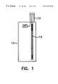
- FIG. 1shows a hand-held portable communication device provided with a multiple-mode antenna according to one embodiment of the present invention, the antenna being in a retracted position;
- FIG. 2shows the antenna of FIG. 1 in an extended position
- FIG. 3shows an alternative antenna according to a second embodiment of the present invention in an extended position
- FIG. 4is a graphical representation of talk position radiation efficiency in two bands of an antenna according to the present invention.
- FIG. 5is a graphical representation of return loss performance in two bands for an antenna according to the present invention.
- a multiple mode antenna according to the present inventionpreferably uses a dual band base antenna as an active antenna for both the retracted and extended positions of the whip antenna.
- the antenna feed connector between the base antenna and the receiver circuitry of the portable communication deviceis fixed.
- the whip antennais preferably a telescoping antenna to achieve a length which will resonate at multiple frequencies.
- the antenna assemblyincludes a fixed base antenna element 12 and an extendable whip antenna 14 .
- the fixed base antennacan exchange communication signals in multiple bands, and interfaces with transceiver processing circuitry (not shown) contained within the device 10 via an antenna feed connector RF.
- the base antenna 12can be a dual band helix antenna, a multiple band branch printed antenna, or other suitable multiple band antenna. As will be discussed below, a multiple band branch printed antenna is preferred.
- the extendable whip antenna 14shown in a retracted position for storage inside the device 10 , contains several elements arranged to allow the antenna 14 to be extended. The whip antenna 14 and its component elements are better shown and described with respect to FIG. 2 .
- FIG. 2shows the portable communication device 10 and antenna assembly of FIG. 1 in the case where the whip antenna 14 is in an extended position.
- the whip antenna 14includes a tube 16 (of, e.g., plastic or some other suitable non-conductive material) slidably engaged with the device 10 such that the tube 16 can be extended to a position where at least a portion of the tube is located outside the device 10 .
- the tube 16should be provided with a means such as a flange for preventing the entire whip antenna 14 from being removed from the device 10 .
- the whip antenna 14further includes a metal rod 18 .
- the metal rod 18has a first end 18 a which is slidably contained within the tube 16 , and a second end 18 b which is slidably engaged with a metal tube 20 .
- the first and second ends 18preferably have an increased diameter (as compared to the exposed portion) to maintain the integrity of the extendable whip antenna 14 .
- the whip antenna 14further includes a metal tube 20 , within which the second end 18 b of the metal rod 18 is slidably retained.
- the metal tube 20is connected to a rod 22 which is made of plastic or some other suitable non-conductive material.
- rod 22preferably has a length which corresponds to the length of the dual band base antenna 12 .
- Rod 22further includes a cap portion 24 which prevents the whip antenna elements from being pushed too far into the device 10 , and which facilitates the retraction and extension of the whip antenna 14 .
- the whip antenna 14in the extended position shown in FIG. 2, operates as a parasitic antenna.
- the metal rod 18is exposed outside of the tubes 16 and 20 and is connected to the conductive metal tube 20 .
- the whip antenna 14in the extended position, is electromagnetically coupled with the base antenna 12 , and enhances the performance of the antenna assembly in a manner to be described later.
- the single antenna feed connectorprovides a common port for both the extended and retracted positions of the whip antenna 14 . There is no matching or switching network required to allow the antenna to resonate at frequencies in different bands.
- FIG. 3shows an alternative embodiment of the whip antenna 14 according to the present invention.
- the metal tube 20is replaced by a non-conductive (e.g., plastic) tube 21 having one or more metal wires arranged in a coil or other suitable fashion.
- the antenna of FIG. 3achieves substantially the same performance as that of FIG. 2 .
- FIG. 4the talk position radiation efficiency of the antenna of FIGS. 1-2 for both the GSM and DCS bands are shown.
- the graph of FIG. 4assumes that the portable communication device 10 is held close to a user's head.
- a typical stub (base) antennaachieves a radiation efficiency of approximately 40% for GSM and approximately 53% for DCS.
- FIG. 4when the length of the metal portion of the whip antenna 14 is approximately 60 mm, a first efficiency peak is achieved for the DCS band only. When this length is increased to approximately 140 mm, a second efficiency peak is reached for both the GSM and DCS bands.
- the antennais resonant for both bands, and the radiation efficiency is improved from the stub antenna case to approximately 59% for GSM and 64% for DCS. These improvements correspond to a gain increase of approximately 3-5 dB for the DCS band, and 5-8 dB for the GSM band. It should be appreciated that the telescoping design of the antenna of the present invention allows this length to be achieved while allowing the antenna to be stored inside the relatively small space available in the portable communication device 10 .
- the distance between the metal portion of the whip antenna 14 and the base antenna 12should be approximately 0.03 wavelength. Because the length between the whip and resonant parts of the base antenna should be measured in wavelength, the distance is ideally closer for DCS than for GSM.
- the extendable whip antenna according to the present inventionis preferably used in conjunction with a base antenna such as that described in Applicant's copending, commonly assigned application entitled “Multi Band Multiple Branch Antenna for Mobile Phone”, the entirety of which is hereby incorporated by reference.
- a branch antennais particularly suitable for a base antenna in a dual band application because it has separate branches corresponding to different frequencies.
- the distance between the metal portion of the whip antenna 14 and the relevant antenna branchshould be approximately 9 mm for GSM, and approximately 4.5 mm for DCS, which can be achieved by selecting the length and arrangement of the crotch antenna branches.
- a graphical representation of return loss for retracted and extended casesis shown in FIG. 5 . The graph assumes the coupling distances described above.
- the antennacan alternatively be designed to achieve resonance in the PCS band (which operates at approximately 1900 MHZ) or other frequency bands.
Landscapes
- Physics & Mathematics (AREA)
- Electromagnetism (AREA)
- Engineering & Computer Science (AREA)
- Computer Networks & Wireless Communication (AREA)
- Support Of Aerials (AREA)
- Details Of Aerials (AREA)
- Variable-Direction Aerials And Aerial Arrays (AREA)
- Transceivers (AREA)
Abstract
Description
Claims (6)
Priority Applications (10)
| Application Number | Priority Date | Filing Date | Title |
|---|---|---|---|
| US08/958,842US6310578B1 (en) | 1997-10-28 | 1997-10-28 | Multiple band telescope type antenna for mobile phone |
| EP98949274AEP1025612A1 (en) | 1997-10-28 | 1998-10-13 | Multiple band telescope type antenna for mobile phone |
| KR1020007004528AKR100601231B1 (en) | 1997-10-28 | 1998-10-13 | Multiband Telescopic Antenna for Mobile Phones |
| IL13574798AIL135747A0 (en) | 1997-10-28 | 1998-10-13 | Multiple band telescope type antenna for mobile phone |
| JP2000518423AJP2001521358A (en) | 1997-10-28 | 1998-10-13 | Multiple band telescope type antenna for mobile phone |
| PCT/SE1998/001845WO1999022419A1 (en) | 1997-10-28 | 1998-10-13 | Multiple band telescope type antenna for mobile phone |
| HK01105191.5AHK1034606B (en) | 1997-10-28 | 1998-10-13 | Multiple band telescope type antenna for mobile phone |
| AU95628/98AAU9562898A (en) | 1997-10-28 | 1998-10-13 | Multiple band telescope type antenna for mobile phone |
| CNB988123916ACN1196227C (en) | 1997-10-28 | 1998-10-13 | Multiband Whip Antenna for Mobile Phone |
| TW087117929ATW392374B (en) | 1997-10-28 | 1998-10-29 | Multiple band telescope type antenna for mobile phone |
Applications Claiming Priority (1)
| Application Number | Priority Date | Filing Date | Title |
|---|---|---|---|
| US08/958,842US6310578B1 (en) | 1997-10-28 | 1997-10-28 | Multiple band telescope type antenna for mobile phone |
Publications (1)
| Publication Number | Publication Date |
|---|---|
| US6310578B1true US6310578B1 (en) | 2001-10-30 |
Family
ID=25501376
Family Applications (1)
| Application Number | Title | Priority Date | Filing Date |
|---|---|---|---|
| US08/958,842Expired - LifetimeUS6310578B1 (en) | 1997-10-28 | 1997-10-28 | Multiple band telescope type antenna for mobile phone |
Country Status (9)
| Country | Link |
|---|---|
| US (1) | US6310578B1 (en) |
| EP (1) | EP1025612A1 (en) |
| JP (1) | JP2001521358A (en) |
| KR (1) | KR100601231B1 (en) |
| CN (1) | CN1196227C (en) |
| AU (1) | AU9562898A (en) |
| IL (1) | IL135747A0 (en) |
| TW (1) | TW392374B (en) |
| WO (1) | WO1999022419A1 (en) |
Cited By (18)
| Publication number | Priority date | Publication date | Assignee | Title |
|---|---|---|---|---|
| US6556171B2 (en)* | 2001-02-06 | 2003-04-29 | Motorola, Inc. | Extendible antenna with articulating hinge |
| US6647245B1 (en)* | 1999-05-28 | 2003-11-11 | Glen V Rosenbaum | Subsidiary communication authorization (SCA) radio turner |
| US20030224738A1 (en)* | 2002-05-28 | 2003-12-04 | Nobuya Harano | Mobile wireless terminal |
| US6703978B2 (en)* | 2002-04-22 | 2004-03-09 | Kyocera Wireless Corp. | Dual telescopic whip antenna |
| US20040119649A1 (en)* | 2002-12-18 | 2004-06-24 | Sullivan Jonathan L. | Antenna with cap |
| US20040189536A1 (en)* | 2001-06-27 | 2004-09-30 | Byung-Hoon Ryou | Antenna for portable wireless communication apparatuses |
| US20050007282A1 (en)* | 2003-05-14 | 2005-01-13 | Matti Martiskainen | Antenna |
| US20050210234A1 (en)* | 2004-03-17 | 2005-09-22 | Best Fiona S | Reach-back communications terminal with selectable networking options |
| US20050208986A1 (en)* | 2004-03-17 | 2005-09-22 | Best Fiona S | Four frequency band single GSM antenna |
| US20050210235A1 (en)* | 2004-03-17 | 2005-09-22 | Best Fiona S | Encryption STE communications through private branch exchange (PBX) |
| US20060290577A1 (en)* | 2005-06-09 | 2006-12-28 | Mete Ozkar | Retractable stubby antenna |
| US20070019414A1 (en)* | 2005-07-22 | 2007-01-25 | Diehl Bgt Defence Gmbh & Co., Kg | Microwave generator with variable frequency emission |
| US20090102726A1 (en)* | 2005-09-09 | 2009-04-23 | Matsushita Electric Industrial Co., Ltd. | Wireless unit antenna apparatus and mobile wireless unit |
| US20110237247A1 (en)* | 2004-03-17 | 2011-09-29 | Best Fiona S | Secure transmission over satellite phone network |
| US20120019422A1 (en)* | 2010-06-01 | 2012-01-26 | Syntonics, Llc | Damage Resistant Antenna |
| US8154462B2 (en) | 1999-09-20 | 2012-04-10 | Fractus, S.A. | Multilevel antennae |
| US9806396B2 (en) | 2012-09-28 | 2017-10-31 | Huawei Device Co., Ltd. | Antenna, combination antenna, and mobile terminal |
| RU179552U1 (en)* | 2017-12-18 | 2018-05-17 | Акционерное общество "Воронежский научно-исследовательский институт "Вега" (АО "ВНИИ "Вега") | ANTENNA |
Families Citing this family (6)
| Publication number | Priority date | Publication date | Assignee | Title |
|---|---|---|---|---|
| JP3395696B2 (en) | 1999-03-15 | 2003-04-14 | 日本電気株式会社 | Wafer processing apparatus and wafer processing method |
| JP3492613B2 (en) | 2000-04-14 | 2004-02-03 | 埼玉日本電気株式会社 | Antenna for portable radio |
| KR100868511B1 (en)* | 2007-07-13 | 2008-11-12 | 주식회사 메닉스 | Flexible Swivel Antenna |
| CN101640949B (en)* | 2009-06-29 | 2012-07-25 | 惠州Tcl移动通信有限公司 | Multi-antenna wireless transceiving device |
| CN102891375A (en)* | 2012-09-29 | 2013-01-23 | 华为终端有限公司 | Television antenna mounted on terminal device and terminal device |
| CN104300234B (en)* | 2013-07-15 | 2018-03-23 | 联想(北京)有限公司 | Antenna assembly, electronic equipment and the method for controlling the antenna assembly |
Citations (20)
| Publication number | Priority date | Publication date | Assignee | Title |
|---|---|---|---|---|
| US676332A (en) | 1901-02-23 | 1901-06-11 | Marconi Wireless Telegraph Co | Apparatus for wireless telegraphy. |
| DE3129045A1 (en) | 1981-04-08 | 1982-10-28 | C. Plath Gmbh Nautisch-Elektronische Technik, 2000 Hamburg | Direction-finding antenna system |
| US4868576A (en) | 1988-11-02 | 1989-09-19 | Motorola, Inc. | Extendable antenna for portable cellular telephones with ground radiator |
| FR2664749A1 (en) | 1990-07-11 | 1992-01-17 | Univ Rennes | Microwave antenna |
| EP0511577A2 (en) | 1991-04-30 | 1992-11-04 | Siemens Aktiengesellschaft | Compact, in particular portable radio transceiver with retractable or collapsible antenna |
| JPH0637531A (en) | 1992-07-17 | 1994-02-10 | Sansei Denki Kk | Wide band helical antenna and its production |
| US5317325A (en) | 1991-03-16 | 1994-05-31 | Antenna Products Limited | Radio antennas |
| US5446469A (en) | 1993-01-14 | 1995-08-29 | Nippon Antenna Co., Ltd. | Extendible whip antenna |
| US5467096A (en) | 1993-02-25 | 1995-11-14 | Nec Corporation | Antenna for a radio communication apparatus |
| US5546094A (en) | 1993-07-26 | 1996-08-13 | Harada Kogyo Kabushiki Kaisha | Telescopic antenna for portable telephones |
| US5548827A (en) | 1993-09-16 | 1996-08-20 | Fujitsu Limited | Portable radio communication device capable of transmitting the same level of electrical energy when the antenna is stored or extended |
| US5550820A (en) | 1992-09-29 | 1996-08-27 | Com 21, Inc. | Multiple protocol personal communications network system |
| US5594457A (en) | 1995-04-21 | 1997-01-14 | Centurion International, Inc. | Retractable antenna |
| US5612704A (en) | 1993-12-22 | 1997-03-18 | Nokia Mobile Phones Ltd. | Retractable antenna |
| US5635943A (en) | 1995-10-16 | 1997-06-03 | Matsushita Communication Industrial Corp. Of America | Transceiver having retractable antenna assembly |
| US5661496A (en) | 1995-03-22 | 1997-08-26 | Ace Antenna Corporation | Capacitive coupled extendable antenna |
| JPH10173430A (en) | 1996-08-22 | 1998-06-26 | Lk Prod Oy | Two-frequency antenna |
| US5945953A (en)* | 1997-04-30 | 1999-08-31 | Sony Corporation | Retractable antenna assembly for a portable radio apparatus |
| US5945964A (en)* | 1997-02-19 | 1999-08-31 | Motorola, Inc. | Multi-band antenna structure for a portable radio |
| US6031493A (en)* | 1995-02-07 | 2000-02-29 | Sony Corporation | Antenna for two frequency bands |
Family Cites Families (6)
| Publication number | Priority date | Publication date | Assignee | Title |
|---|---|---|---|---|
| US4169267A (en)* | 1978-06-19 | 1979-09-25 | The United States Of America As Represented By The Secretary Of The Air Force | Broadband helical antennas |
| JP2731188B2 (en)* | 1988-11-08 | 1998-03-25 | 株式会社東芝 | Telescopic antenna and radio |
| SE512062C2 (en)* | 1993-07-14 | 2000-01-17 | Ericsson Ge Mobile Communicat | Method and apparatus for improving the efficiency and bandwidth of an antenna on a portable equipment |
| SE514027C2 (en)* | 1993-10-29 | 2000-12-11 | Allgon Ab | Broadband antenna device |
| FI98165C (en)* | 1995-06-05 | 1997-04-25 | Lk Products Oy | Dual function antenna |
| FI113214B (en)* | 1997-01-24 | 2004-03-15 | Filtronic Lk Oy | Simple dual frequency antenna |
- 1997
- 1997-10-28USUS08/958,842patent/US6310578B1/ennot_activeExpired - Lifetime
- 1998
- 1998-10-13WOPCT/SE1998/001845patent/WO1999022419A1/enactiveIP Right Grant
- 1998-10-13JPJP2000518423Apatent/JP2001521358A/enactivePending
- 1998-10-13AUAU95628/98Apatent/AU9562898A/ennot_activeAbandoned
- 1998-10-13ILIL13574798Apatent/IL135747A0/enunknown
- 1998-10-13CNCNB988123916Apatent/CN1196227C/ennot_activeExpired - Fee Related
- 1998-10-13KRKR1020007004528Apatent/KR100601231B1/ennot_activeExpired - Fee Related
- 1998-10-13EPEP98949274Apatent/EP1025612A1/ennot_activeWithdrawn
- 1998-10-29TWTW087117929Apatent/TW392374B/ennot_activeIP Right Cessation
Patent Citations (20)
| Publication number | Priority date | Publication date | Assignee | Title |
|---|---|---|---|---|
| US676332A (en) | 1901-02-23 | 1901-06-11 | Marconi Wireless Telegraph Co | Apparatus for wireless telegraphy. |
| DE3129045A1 (en) | 1981-04-08 | 1982-10-28 | C. Plath Gmbh Nautisch-Elektronische Technik, 2000 Hamburg | Direction-finding antenna system |
| US4868576A (en) | 1988-11-02 | 1989-09-19 | Motorola, Inc. | Extendable antenna for portable cellular telephones with ground radiator |
| FR2664749A1 (en) | 1990-07-11 | 1992-01-17 | Univ Rennes | Microwave antenna |
| US5317325A (en) | 1991-03-16 | 1994-05-31 | Antenna Products Limited | Radio antennas |
| EP0511577A2 (en) | 1991-04-30 | 1992-11-04 | Siemens Aktiengesellschaft | Compact, in particular portable radio transceiver with retractable or collapsible antenna |
| JPH0637531A (en) | 1992-07-17 | 1994-02-10 | Sansei Denki Kk | Wide band helical antenna and its production |
| US5550820A (en) | 1992-09-29 | 1996-08-27 | Com 21, Inc. | Multiple protocol personal communications network system |
| US5446469A (en) | 1993-01-14 | 1995-08-29 | Nippon Antenna Co., Ltd. | Extendible whip antenna |
| US5467096A (en) | 1993-02-25 | 1995-11-14 | Nec Corporation | Antenna for a radio communication apparatus |
| US5546094A (en) | 1993-07-26 | 1996-08-13 | Harada Kogyo Kabushiki Kaisha | Telescopic antenna for portable telephones |
| US5548827A (en) | 1993-09-16 | 1996-08-20 | Fujitsu Limited | Portable radio communication device capable of transmitting the same level of electrical energy when the antenna is stored or extended |
| US5612704A (en) | 1993-12-22 | 1997-03-18 | Nokia Mobile Phones Ltd. | Retractable antenna |
| US6031493A (en)* | 1995-02-07 | 2000-02-29 | Sony Corporation | Antenna for two frequency bands |
| US5661496A (en) | 1995-03-22 | 1997-08-26 | Ace Antenna Corporation | Capacitive coupled extendable antenna |
| US5594457A (en) | 1995-04-21 | 1997-01-14 | Centurion International, Inc. | Retractable antenna |
| US5635943A (en) | 1995-10-16 | 1997-06-03 | Matsushita Communication Industrial Corp. Of America | Transceiver having retractable antenna assembly |
| JPH10173430A (en) | 1996-08-22 | 1998-06-26 | Lk Prod Oy | Two-frequency antenna |
| US5945964A (en)* | 1997-02-19 | 1999-08-31 | Motorola, Inc. | Multi-band antenna structure for a portable radio |
| US5945953A (en)* | 1997-04-30 | 1999-08-31 | Sony Corporation | Retractable antenna assembly for a portable radio apparatus |
Non-Patent Citations (3)
| Title |
|---|
| "Antennas" by J.D. Kraus, (McGraw-Hill Book Co., Inc.) pp. 173-178 (1950). |
| "Microwave Scanning Antennas" edited by R.C. Hansen, Peninsula Publishing, pp. 116-122 (1950). |
| Patent Abstracts of Japan, JP-0236602, Sep. 30, 1994. |
Cited By (40)
| Publication number | Priority date | Publication date | Assignee | Title |
|---|---|---|---|---|
| US6647245B1 (en)* | 1999-05-28 | 2003-11-11 | Glen V Rosenbaum | Subsidiary communication authorization (SCA) radio turner |
| US9362617B2 (en) | 1999-09-20 | 2016-06-07 | Fractus, S.A. | Multilevel antennae |
| US8154463B2 (en) | 1999-09-20 | 2012-04-10 | Fractus, S.A. | Multilevel antennae |
| US8330659B2 (en) | 1999-09-20 | 2012-12-11 | Fractus, S.A. | Multilevel antennae |
| US8941541B2 (en) | 1999-09-20 | 2015-01-27 | Fractus, S.A. | Multilevel antennae |
| US8976069B2 (en) | 1999-09-20 | 2015-03-10 | Fractus, S.A. | Multilevel antennae |
| US9000985B2 (en) | 1999-09-20 | 2015-04-07 | Fractus, S.A. | Multilevel antennae |
| US9054421B2 (en) | 1999-09-20 | 2015-06-09 | Fractus, S.A. | Multilevel antennae |
| US9240632B2 (en) | 1999-09-20 | 2016-01-19 | Fractus, S.A. | Multilevel antennae |
| US10056682B2 (en) | 1999-09-20 | 2018-08-21 | Fractus, S.A. | Multilevel antennae |
| US8154462B2 (en) | 1999-09-20 | 2012-04-10 | Fractus, S.A. | Multilevel antennae |
| US9761934B2 (en) | 1999-09-20 | 2017-09-12 | Fractus, S.A. | Multilevel antennae |
| US6556171B2 (en)* | 2001-02-06 | 2003-04-29 | Motorola, Inc. | Extendible antenna with articulating hinge |
| US6911943B2 (en)* | 2001-06-27 | 2005-06-28 | E.M.W. Antenna Co., Ltd. | Antenna for portable wireless communication apparatuses |
| US20040189536A1 (en)* | 2001-06-27 | 2004-09-30 | Byung-Hoon Ryou | Antenna for portable wireless communication apparatuses |
| US6703978B2 (en)* | 2002-04-22 | 2004-03-09 | Kyocera Wireless Corp. | Dual telescopic whip antenna |
| US7386281B2 (en)* | 2002-05-28 | 2008-06-10 | Nec Corporation | Mobile wireless terminal |
| US20030224738A1 (en)* | 2002-05-28 | 2003-12-04 | Nobuya Harano | Mobile wireless terminal |
| US6788260B2 (en)* | 2002-12-18 | 2004-09-07 | Centurion Wireless Technologies, Inc. | Antenna with cap |
| US20040119649A1 (en)* | 2002-12-18 | 2004-06-24 | Sullivan Jonathan L. | Antenna with cap |
| US7167131B2 (en)* | 2003-05-14 | 2007-01-23 | Galtronics Ltd. | Antenna |
| US20050007282A1 (en)* | 2003-05-14 | 2005-01-13 | Matti Martiskainen | Antenna |
| US20050208986A1 (en)* | 2004-03-17 | 2005-09-22 | Best Fiona S | Four frequency band single GSM antenna |
| US20050210235A1 (en)* | 2004-03-17 | 2005-09-22 | Best Fiona S | Encryption STE communications through private branch exchange (PBX) |
| US8239669B2 (en) | 2004-03-17 | 2012-08-07 | Telecommunication Systems, Inc. | Reach-back communications terminal with selectable networking options |
| US8280466B2 (en)* | 2004-03-17 | 2012-10-02 | Telecommunication Systems, Inc. | Four frequency band single GSM antenna |
| US20110237247A1 (en)* | 2004-03-17 | 2011-09-29 | Best Fiona S | Secure transmission over satellite phone network |
| US8489874B2 (en) | 2004-03-17 | 2013-07-16 | Telecommunication Systems, Inc. | Encryption STE communications through private branch exchange (PBX) |
| US20050210234A1 (en)* | 2004-03-17 | 2005-09-22 | Best Fiona S | Reach-back communications terminal with selectable networking options |
| US8913989B2 (en) | 2004-03-17 | 2014-12-16 | Telecommunication Systems, Inc. | Secure transmission over satellite phone network |
| US20060290577A1 (en)* | 2005-06-09 | 2006-12-28 | Mete Ozkar | Retractable stubby antenna |
| US7224316B2 (en)* | 2005-06-09 | 2007-05-29 | Kyocera Wireless Corp. | Retractable stubby antenna |
| US7626468B2 (en)* | 2005-07-22 | 2009-12-01 | Diehl Bgt Defence Gmbh & Co., Kg | Microwave generator with variable frequency emission |
| US20070019414A1 (en)* | 2005-07-22 | 2007-01-25 | Diehl Bgt Defence Gmbh & Co., Kg | Microwave generator with variable frequency emission |
| US20090102726A1 (en)* | 2005-09-09 | 2009-04-23 | Matsushita Electric Industrial Co., Ltd. | Wireless unit antenna apparatus and mobile wireless unit |
| US7852272B2 (en)* | 2005-09-09 | 2010-12-14 | Panasonic Corporation | Wireless unit antenna apparatus and mobile wireless unit |
| US20120019422A1 (en)* | 2010-06-01 | 2012-01-26 | Syntonics, Llc | Damage Resistant Antenna |
| US8711048B2 (en)* | 2010-06-01 | 2014-04-29 | Syntonics, Llc | Damage resistant antenna |
| US9806396B2 (en) | 2012-09-28 | 2017-10-31 | Huawei Device Co., Ltd. | Antenna, combination antenna, and mobile terminal |
| RU179552U1 (en)* | 2017-12-18 | 2018-05-17 | Акционерное общество "Воронежский научно-исследовательский институт "Вега" (АО "ВНИИ "Вега") | ANTENNA |
Also Published As
| Publication number | Publication date |
|---|---|
| WO1999022419A1 (en) | 1999-05-06 |
| CN1282451A (en) | 2001-01-31 |
| KR100601231B1 (en) | 2006-07-19 |
| HK1034606A1 (en) | 2001-10-26 |
| AU9562898A (en) | 1999-05-17 |
| EP1025612A1 (en) | 2000-08-09 |
| JP2001521358A (en) | 2001-11-06 |
| CN1196227C (en) | 2005-04-06 |
| KR20010031491A (en) | 2001-04-16 |
| TW392374B (en) | 2000-06-01 |
| IL135747A0 (en) | 2001-05-20 |
Similar Documents
| Publication | Publication Date | Title |
|---|---|---|
| US6310578B1 (en) | Multiple band telescope type antenna for mobile phone | |
| KR100384656B1 (en) | Dual-band helix antenna with parasitic element | |
| US6342859B1 (en) | Ground extension arrangement for coupling to ground means in an antenna system, and an antenna system and a mobile radio device having such ground arrangement | |
| US6329962B2 (en) | Multiple band, multiple branch antenna for mobile phone | |
| US6611691B1 (en) | Antenna adapted to operate in a plurality of frequency bands | |
| JP2764348B2 (en) | Antenna device for portable device | |
| US6057807A (en) | Dual band antenna means incorporating helical and elongated radiating structures | |
| JPH0770896B2 (en) | Extendable antenna system and portable radio using the same | |
| AU2550899A (en) | Dual band antenna for radio terminal | |
| JP2001522152A (en) | Multiple band, multiple branch antenna for mobile phone | |
| CA2277154C (en) | Dual band antenna | |
| JPH07122917A (en) | Broadband antenna that can be inserted and removed for mobile phones | |
| JP2002500456A (en) | Retractable radiotelephone antenna with extended feeder | |
| GB2335312A (en) | An antenna adapted to operate in a plurality of frequency bands | |
| EP0459391B1 (en) | Antenna for portable radio equipment | |
| GB2316539A (en) | A broadband monopole antenna | |
| EP1203495A1 (en) | Dual band antenna device | |
| JP3225438B2 (en) | Telescopic multi-band whip antenna | |
| JP3904957B2 (en) | Dual-band antenna structure for mobile phones | |
| JP2896391B2 (en) | Antenna device | |
| HK1034606B (en) | Multiple band telescope type antenna for mobile phone | |
| WO1999054959A1 (en) | Antenna means and a handheld radio communication device including such means | |
| KR20000016682A (en) | Meander antenna device |
Legal Events
| Date | Code | Title | Description |
|---|---|---|---|
| AS | Assignment | Owner name:TELEFONAKTIEBOLAGET LM ERICSSON, SWEDEN Free format text:ASSIGNMENT OF ASSIGNORS INTEREST;ASSIGNOR:YING, ZHINONG;REEL/FRAME:008871/0892 Effective date:19971027 | |
| STCF | Information on status: patent grant | Free format text:PATENTED CASE | |
| FEPP | Fee payment procedure | Free format text:PAYOR NUMBER ASSIGNED (ORIGINAL EVENT CODE: ASPN); ENTITY STATUS OF PATENT OWNER: LARGE ENTITY | |
| FPAY | Fee payment | Year of fee payment:4 | |
| FPAY | Fee payment | Year of fee payment:8 | |
| FPAY | Fee payment | Year of fee payment:12 | |
| AS | Assignment | Owner name:HIGHBRIDGE PRINCIPAL STRATEGIES, LLC (AS COLLATERA Free format text:LIEN;ASSIGNOR:OPTIS CELLULAR TECHNOLOGY, LLC;REEL/FRAME:031866/0697 Effective date:20131219 | |
| AS | Assignment | Owner name:WILMINGTON TRUST, NATIONAL ASSOCIATION (AS COLLATE Free format text:SECURITY AGREEMENT;ASSIGNOR:OPTIS CELLULAR TECHNOLOGY, LLC;REEL/FRAME:032167/0406 Effective date:20131219 | |
| AS | Assignment | Owner name:OPTIS CELLULAR TECHNOLOGY, LLC, TEXAS Free format text:ASSIGNMENT OF ASSIGNORS INTEREST;ASSIGNOR:CLUSTER LLC;REEL/FRAME:032326/0402 Effective date:20131219 Owner name:CLUSTER LLC, DELAWARE Free format text:ASSIGNMENT OF ASSIGNORS INTEREST;ASSIGNOR:TELEFONAKTIEBOLAGET L M ERICSSON (PUBL);REEL/FRAME:032326/0219 Effective date:20131219 | |
| AS | Assignment | Owner name:HIGHBRIDGE PRINCIPAL STRATEGIES, LLC, AS COLLATERA Free format text:ASSIGNMENT OF ASSIGNORS INTEREST;ASSIGNOR:OPTIS CELLULAR TECHNOLOGY, LLC;REEL/FRAME:032786/0546 Effective date:20140424 | |
| AS | Assignment | Owner name:HIGHBRIDGE PRINCIPAL STRATEGIES, LLC, AS COLLATERA Free format text:CORRECTIVE ASSIGNMENT TO CORRECT THE NATURE OF CONVEYANCE TO READ "SECURITY INTEREST" PREVIOUSLY RECORDED ON REEL 032786 FRAME 0546. ASSIGNOR(S) HEREBY CONFIRMS THE SECURITY INTEREST;ASSIGNOR:OPTIS CELLULAR TECHNOLOGY, LLC;REEL/FRAME:033281/0216 Effective date:20140424 | |
| AS | Assignment | Owner name:OPTIS CELLULAR TECHNOLOGY, LLC, TEXAS Free format text:RELEASE BY SECURED PARTY;ASSIGNOR:HPS INVESTMENT PARTNERS, LLC;REEL/FRAME:039359/0916 Effective date:20160711 |