US6310335B1 - Translational braking device for a projectile during its trajectory - Google Patents
Translational braking device for a projectile during its trajectoryDownload PDFInfo
- Publication number
- US6310335B1 US6310335B1US09/450,689US45068999AUS6310335B1US 6310335 B1US6310335 B1US 6310335B1US 45068999 AUS45068999 AUS 45068999AUS 6310335 B1US6310335 B1US 6310335B1
- Authority
- US
- United States
- Prior art keywords
- flap
- projectile
- braking device
- flaps
- translational braking
- Prior art date
- Legal status (The legal status is an assumption and is not a legal conclusion. Google has not performed a legal analysis and makes no representation as to the accuracy of the status listed.)
- Expired - Lifetime
Links
Images


Classifications
- F—MECHANICAL ENGINEERING; LIGHTING; HEATING; WEAPONS; BLASTING
- F42—AMMUNITION; BLASTING
- F42B—EXPLOSIVE CHARGES, e.g. FOR BLASTING, FIREWORKS, AMMUNITION
- F42B10/00—Means for influencing, e.g. improving, the aerodynamic properties of projectiles or missiles; Arrangements on projectiles or missiles for stabilising, steering, range-reducing, range-increasing or fall-retarding
- F42B10/32—Range-reducing or range-increasing arrangements; Fall-retarding means
- F42B10/48—Range-reducing, destabilising or braking arrangements, e.g. impact-braking arrangements; Fall-retarding means, e.g. balloons, rockets for braking or fall-retarding
- F42B10/50—Brake flaps, e.g. inflatable
Definitions
- the technical scope of the inventionis that of translational braking devices for a projectile during its trajectory.
- Such devicesare notably known in the field of artillery.
- Patent EP138942thusdescribes an artillery projectile that incorporates a device to brake the nose cone whose deployment is controlled during the trajectory.
- Such an arrangementallows firing accuracy of artillery fires to be increased whilst taking into account dispersions due to the variations in initial velocity of the projectile. Indeed, it is thus possible to lay the weapon so as to fire beyond the target aimed at, a fire control measures the real velocity of the projectile at the muzzle of the weapon and a braking command is thereafter transmitted to the projectile so as to reduce its range and thus bring it to the desired point of impact.
- the braking device described by this patentcomprises, either radially mobile fingers, or a plane frontal surface.
- the surface area of these braking means with respect to the section of the projectileis too small for their braking capacity to be sufficient.
- Patent WO98/01719describes another braking device for a projectile. This device comprises four airbrake plates stacked one on top of the other and radially mobile with respect to the projectile.
- the braking areais thus substantially increased (it constitutes approximately double the section of the projectile) and is of a reduced bulk inside the projectile body.
- the shapes of the platesare complicated to machine, they also incorporate numerous indents that reduce their mechanical strength, notably in their fully deployed position where the stresses are at their worst.
- the platesare unlocked by means of two gas generators that displace two retention pins, each pin immobilizing two plates.
- Such a structureis likely to cause dissymmetries or sticking when the plates are deploying that risk modifying the trajectory of the projectile in a non-reproducible manner.
- the aim of the inventionis to propose a translational braking device for a projectile that does not have such drawbacks.
- the braking device according to the inventionis of a simple inexpensive design and has improved mechanical strength with respect to the previously described device.
- the subject of the inventionis a translational braking device for a projectile during its trajectory comprising at least two airbrakes that are radially deployable so as to increase the projectile's aerodynamic drag, wherein each airbrake is a flap pivoting around a pivot integral with the projectile and parallel to its axis.
- the braking deviceincorporates at least one pyrotechnic piston locking at least one of the flaps in its folded position.
- At least two flapsare stacked one on top of the other when they are in their folded position, at least a first of the two flaps incorporating means to retain the second of the two flaps in its folded position.
- the braking devicecan, advantageously, incorporate at least four flaps, a first flap being locked by the pyrotechnic piston and carrying a first pin retaining a second flap in its folded position, a third flap carrying a second pin co-operating with a first retention surface integral with the second flap, a fourth flap carrying a third pin co-operating with a second retention surface integral with the third flap, a single pyrotechnic piston thereby ensuring the locking of all four flaps.
- Each flapcan have an external profile covering the arc of a circle whose diameter is substantially equal to that of an external part of the projectile and an indent intended to allow the flap to fold around an axial support integral with the projectile.
- Each flapcan, advantageously, incorporate an abutment heel intended to co-operate with a matching surface of the axial support so as to stop the opening movement of the flap.
- the arc length of the external profile of each flap and the length of the different heelscan be selected such that, in the deployed position, the free end of at least one flap presses on a neighboring flap or else on the projectile.
- the axial supportscan carry two plates, a lower plate and an upper plate, each plate supporting at least two pivots of the flaps that are thus arranged between the two plates when they are in the folded position.
- each flapcan incorporate a toothed circular portion arranged around the pivot , such portion meshing with a central pinion coaxial to the projectile, such central pinion thereby joining together the different flaps.
- the pyrotechnic pistoncan, advantageously, lock the central pinion.
- the flapscan, in any case, be integral with a nose cone fuse of the projectile.
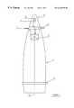
- FIG. 1schematically shows a projectile fitted with a braking device according to the invention
- FIG. 2shows a partial longitudinal section view of a projectile fuse fitted with a braking device according to a first embodiment of the invention
- FIG. 3shows this same device in the folded position and as a section along plane AA referenced in FIG. 2,
- FIG. 4is an analogous view to FIG. 3 but shows the device in the deployed position
- FIGS. 5 a to 5 hshow the braking flaps alone, FIGS. 5 a , 5 c , 5 e , and 5 g being frontal views of said flaps and FIGS. 5 b , 5 d , 5 f , and 5 h being lateral views of the different flaps, each of the frontal views being associated with its lateral view for a given flap ( 5 a / 5 b , 5 c / 5 d , 5 e / 5 f and 5 g / 5 h ),
- FIGS. 6 and 7are partial section views of two types of flap hinges
- FIG. 8shows a section view in the deployed position of a device according to a first embodiment
- FIG. 9shows a partial longitudinal section view of a projectile fuse fitted with a braking device according to a second embodiment of the invention.
- FIG. 10shows this same device in the deployed position and as a section along plane BB referenced on FIG. 9 .
- an artillery projectile 1is fitted, at its rear part, with a belt 2 intended to mesh in the rifling of a weapon barrel (not shown) and to provide sealing against the propellant gases when the projectile is fired.
- this projectilecarries a fuse 3 that is intended, in a conventional manner and according to the type of projectile in question (explosive projectile or carrier projectile), to ensure either the ignition of an explosive charge placed inside the projectile, or the priming of a gas-generating charge intended to eject a payload during the trajectory that has been placed inside the projectile (anti-tank ammunition or grenades).
- the fuse 3incorporates an electronic control device 4 that causes the ignition of a pyrotechnic charge 5 (that, according to the case, is a detonation relay or a gas generator).
- this fuse 3also incorporates a translational braking device 6 enabling the radial deployment during the trajectory of braking flaps 7 .
- the deployment of the flaps 7is controlled by the electronic control device 4 in response to a command received during the trajectory by means of a receiver 8 or else emitted by the electronic control device 4 in accordance with programming made before firing, or else modified in the first moments following firing to take into account the real initial velocity of the projectile.
- FIG. 2shows the fuse 3 in more detail. It has an overall shape and bulk analogous to those of conventional artillery fuses. It incorporates a body 13 onto which threading 9 is made that is intended to allow it to be made integral with the projectile.
- the pyrotechnic charge 5is placed in a bush integral with the body and communicates via a priming channel 10 with an electrically-operated igniting composition 11 (primer or squib), that is itself connected to the electronic control device 4 .
- an electrically-operated igniting composition 11primary or squib
- the igniting component 11is carried by a mobile flap 12 of a safety and arming device.
- the body 13 of the fuse 3incorporates an axial cylinder 14 that connects a lower portion of the fuse 3 incorporating the pyrotechnic charge 5 and an upper portion of the fuse 3 enclosing the electronic device 4 .
- a priming channel 10passes through this cylinder.
- the cylinder 14receives the braking device 6 that comprises an axial fin support 15 incorporating a tubular part 16 and two plates 17 and 18 .
- the tubular part 16is mounted coaxially to the cylinder 14 and thus has an inner diameter that is equal to that of the cylinder 14 .
- the upper 17 and lower 18 platesare plane and perpendicular to the axis 20 of the fuse 3 and the projectile.
- the two plates 17 and 18delimit a ring-shaped volume inside which flaps 7 are placed.
- the fin support 15is made integral in translation and in rotation with the fuse 3 body, for example by a locking nut mounted on the cylinder 14 and not shown.
- flaps 7 a , 7 b , 7 c and 7 dare integral with the support 15 .
- Each flapis hinged with respect to the support around a pivot 19 ( 19 a , 19 b , 19 c , 19 d ) parallel to the axis 20 of the fuse 3 (and thus also of the projectile).
- the pivots 19are only shown schematically in FIG. 2 .
- the upper plate 17carries two pivots 19 a and 19 b that fasten the two flaps 7 a and 7 b .
- the lower plate 18carries two pivots 19 c and 19 d that fasten the two pivots 7 c and 7 d .
- the pivotsare evenly spaced angularly around the axis 20 of the fuse 3 .
- the different flapsare stacked on top of one another when they are in their folded position, the first flap 7 a is in contact with the upper plate 17 and the fourth flap 7 d is in contact with the lower plate 18 .
- the second flap 7 bis placed between the first flap 7 a and the third flap 7 c , said flap 7 c being itself placed between the second flap 7 b and the fourth flap 7 d .
- Such an arrangement of the flapsensures their mechanical resistance to the acceleration developed when the projectile is fired.
- FIGS. 6 and 7show the structure of a pivot 19 in detail.
- FIG. 6shows the structure of a pivot ( 19 a or 19 d ) fastening the flaps that are directly in contact with plates 17 and 18 , that is flaps 7 a and 7 d .
- Pivot 19 a(or 19 d ) is constituted by a nut 21 having an enlarged head 21 a housed in a counter-sink 22 arranged in the flap.
- a screw 23has its head in contact with the plate 17 (or 18 ) and connects the flap and the plate. Play of around a tenth of a millimeter is provided during assembly so as to allow the flap to pivot around hinge pin 24 of pivot 19 .
- FIG. 7shows the structure of a pivot ( 19 b or 19 c ) fastening the flaps that are not directly in contact with the plates 17 and 18 , that is flaps 7 b and 7 c .
- This pivotalso incorporates a nut 21 whose enlarged head is housed in a counter-sink arranged in the flap and a screw 23 whose head is in contact with the plate 17 (or 18 ). It differs from the pivot in FIG. 6 by the presence of a brace 25 ensuring a space between the plate and the flap in question. The thickness of the brace is equal to that of the flap placed between the plate and the intermediate flap in question.
- Each flapcan be seen in greater detail in FIGS. 5 a to 5 h .
- Each flapis made, for example, of steel sheeting of a thickness of 2 mm and that has a perforation 32 intended to receive the pivot 19 and in which is arranged a counter-sink 22 .
- the flapscan also be made of another material, for example a light alloy (aluminum-based).
- Each flaphas an external profile 26 covering the arc of a circle whose diameter is substantially equal to the external diameter of the fuse 3 .
- Each flapalso has an indent 27 intended to allow the flap to be folded around the tubular part 16 of the axial support 15 .
- the indent 27incorporates a hemicylindrical portion 28 of the same diameter as that of the tubular part 16 and coaxial to its axis 20 (that is coaxial also to the axis of the fuse 3 and the projectile).
- the hemicylindrical portion 28 of the indentis connected on one side to a plane surface 29 that is perpendicular to the plane defined by the hinge pin 24 of the pivot 19 in question and the axis 20 of the fuse 3 , and on the other to two cylindrical surfaces 30 and 31 , the first ( 30 ) of which is coaxial to the pivot 19 and the second ( 31 ) having an axis parallel to that of the pivot and a radius equal to that of the tubular part 16 .
- the surface 31constitutes an abutment heel that is intended to co-operate with the axial support 15 to stop the opening movement of the flap 7 .
- the cylindrical surfaces 30 and 31are arranged in the vicinity of the pivot 19 and the axis 20 of the fuse 3 is located between the hinge pin 24 of the pivot and the plane surface 29 . This results in such an arrangement that a pivotal movement of each flap around its hinge pin 24 is allowed without there being any interference between the plane surface 29 and the tubular part 16 . As a result of the shape thus adopted for the flaps, a maximal flap surface area is obtained for a minimal bulk in the folded position.
- the different flapshave certain structural differences with respect to one another.
- the first flap 7 ahas a hole 33 that is intended to receive the rod 35 of a pyrotechnic piston 34 (see FIG. 2 ).
- This pyrotechnic pistonis in this case a pyrotechnic retractor that comprises a gas-generating composition electrically ignited by the control device 4 and whose effect is to cause the retraction of the rod 35 from the hole 33 .
- a pyrotechnic componentis well known to the expert and will therefore not be described here in any further detail.
- the rod 35 of the retractorlocks the first flap 7 a in its folded position.
- the first flap 7 aalso has a first pin 36 that is intended to ensure the retention of the second flap 7 b in its folded position. To this end, it co-operates with a notch 37 made on the external circular profile 26 of the second flap 7 b.
- the third flap 7 chas a second pin 38 that is intended to co-operate with the plane surface 29 of the second flap 7 b when this is in its folded position.
- This plane surfacethen constitutes a first retention surface that prevents the third flap from opening when the second flap is in the folded position.
- the fourth flap 7 dhas a third pin 39 that co-operates in an analogous manner with the plane surface 29 of the third flap 7 c when this is in its folded position.
- This plane surfaceconstitutes a second retention surface that prevents the fourth flap from opening when the third flap is in its folded position.
- a single pyrotechnic piston 34locks all the four flaps 7 a , 7 b , 7 c and 7 d and prevents them from deploying further to the centrifugal forces that are exerted on them when the projectile is fired.
- Pins 36 , 38 and 39are constituted by small cylindrical rods mounted in holes made in the flaps.
- FIG. 3shows the four flaps in the folded locked position.
- the section view of the fuse 3has been carried out so as to remove the upper plate 17 .
- Only the first flap 7 ais fully visible, its pivot 19 a being to the right of the figure with the nut 21 sectioned.
- the second flap 7 bis partially visible in the indent of the first flap, its pivot 19 b is at the top of the figure with the sectioned nut 21 and the brace 25 visible.
- the third flapis hidden, its pivot 19 c is at the bottom of the figure, the fourth flap is also hidden, its pivot 19 d is at the left of the figure.
- This figureshows how the different retention means co-operate to lock the four flaps.
- the pin 38 carried by the third flap 7 cis in contact with the plane surface 29 of the second flap 7 b .
- the third flapis therefore not able to open.
- the pin 39 carried by the fourth flap 7 dis in contact with the plane surface 29 of the third flap 7 c .
- the fourth flapis therefore not able to open.
- the electronic control device 4will cause the rod 35 to retract from the pyrotechnic piston.
- the first flap 7 awill open under the action of the centrifugal force.
- the pin 36thereafter comes out of the notch 37 freeing the second flap 7 b , which can now also open.
- the surface 29moves away from the pin 38 , thereby freeing the third flap 7 c , which in turn opens freeing the fourth flap 7 d.
- FIG. 4shows the flaps in their deployed position.
- each flapis halted by its abutment heel 31 coming into contact with the tubular part 16 of the axial support 15 .
- Such an arrangementenables the angle of opening of the flaps to be controlled.
- the arc length of the external profile 26 of each flap and the length of the different abutment heelsare selected such that, in the deployed position, the free end 40 of each flap (the end that is the furthest away from the pivot 19 ) presses on or lies opposite to a neighboring flap or else presses on or lies opposite to the lower plate 18 (that forms a bearing surface integral with the fuse and thus with the projectile, perpendicular to the projectile axis).
- the fourth flap 7 dpresses by its free end 40 on the lower plate 18 .
- the third flap 7 cpresses by its end 40 on the fourth flap 7 d and opposite plate 18 increasing the rigidity of the bearing.
- the first and second flapshave their free end respectively opposite the third flap and the lower plate 18 .
- the rigidity of the braking device in its deployed positionis improved, and therefore also its mechanical bending strength.
- the opening diameter D obtainedis around 118 mm for an initial diameter of the lower plate of around 61 mm, which represents an increase in the diameter of around 90%.
- the device according to the inventionis thus seen to obtain a substantial, rigid braking surface with a reduced bulk and substantial mechanical strength.
- FIG. 8shows a variant in which the flaps 7 are without the abutment heel. They are therefore able to deploy fully under the effect of the centrifugal force and allow a maximal opening diameter D 1 of around 140 mm to be obtained from an initial diameter of around 61 mm.
- FIGS. 9 and 10show a second embodiment of the invention.
- This embodimentdiffers from the previous ones in that all the flaps 7 are fastened onto the body 13 by screws 41 that constitute the flap pivots. Seven flaps 7 are provided and are stacked on top of one another in the folded position (FIG. 9 ). So as to allow each flap to be fastened to the body 13 , screws 41 of different lengths are provided for each flap as well as suitable braces (not shown).
- Each flap 7is constituted by a piece of steel sheeting that has an external profile 26 covering an arc of a circle whose diameter is substantially equal to the external diameter of the fuse.
- Each flap 7also has an indent 27 comprising a hemicylindrical portion 28 intended to allow the flap to fold around the axial cylinder 14 integral with the fuse body 13 and coaxial to its axis 20 (that is also coaxial to the fuse and the projectile).
- a central cylindrical pinion 42is mounted coaxially to the axial cylinder 14 and is free to rotate with respect to said cylinder.
- the teeth of the pinionare parallel to the axis 20 of the fuse and mesh with toothed circular portions 43 made on all the flaps 7 and coaxial with their pivot 41 .
- the central pinion 42incorporates an upper flange 44 in which a hole has been made into which the rod 35 of the pyrotechnic piston 34 is housed thereby immobilizing the central pinion 42 in rotation, and thus locking all the flaps in their folded position against the effects of the centrifugal force.
- This deviceoperates as follows:
- the electronic control devicewill ignite the pyrotechnic piston 34 .
- the rod 35is extracted from its hole in the flange 44 of the pinion 42 thus unlocking it.
- the centrifugal force exerted on the flapswill cause them to open, such opening being symmetrical with respect to the axis 20 of the projectile because of the presence of the toothed portions 43 and central pinion 42 .
- the flapscontinue to open until reaching the position shown in FIG. 10 in which the flaps abut against the central pinion.
- the opening angle of the different flapscan be controlled by acting on the length of their toothed circular portion.
- the opening of a flapcan not continue beyond the possible relative course of this toothed portion on the central pinion.
- Opening diameter D 2 that can be obtained with this embodiment of the inventionis of around 130 mm from an initial diameter of around 61 mm.
- the inventioncan naturally be applied to all types of large-caliber projectiles (over 50 mm) or medium-caliber projectiles (less than or equal to 50 mm).
Landscapes
- Physics & Mathematics (AREA)
- Fluid Mechanics (AREA)
- Engineering & Computer Science (AREA)
- General Engineering & Computer Science (AREA)
- Vibration Dampers (AREA)
- Aiming, Guidance, Guns With A Light Source, Armor, Camouflage, And Targets (AREA)
Abstract
Description
Claims (19)
Applications Claiming Priority (2)
| Application Number | Priority Date | Filing Date | Title |
|---|---|---|---|
| FR9815101AFR2786561B1 (en) | 1998-11-30 | 1998-11-30 | DEVICE FOR BRAKING IN TRANSLATION OF A PROJECTILE ON A TRAJECTORY |
| FR9815101 | 1998-11-30 |
Publications (1)
| Publication Number | Publication Date |
|---|---|
| US6310335B1true US6310335B1 (en) | 2001-10-30 |
Family
ID=9533397
Family Applications (1)
| Application Number | Title | Priority Date | Filing Date |
|---|---|---|---|
| US09/450,689Expired - LifetimeUS6310335B1 (en) | 1998-11-30 | 1999-11-30 | Translational braking device for a projectile during its trajectory |
Country Status (4)
| Country | Link |
|---|---|
| US (1) | US6310335B1 (en) |
| EP (1) | EP1006335B1 (en) |
| DE (1) | DE69909719T2 (en) |
| FR (1) | FR2786561B1 (en) |
Cited By (13)
| Publication number | Priority date | Publication date | Assignee | Title |
|---|---|---|---|---|
| US6502786B2 (en)* | 2001-02-01 | 2003-01-07 | United Defense, L.P. | 2-D projectile trajectory corrector |
| US20030047645A1 (en)* | 2001-05-25 | 2003-03-13 | Rastegar Jahangir S. | Methods and apparatus for increasing aerodynamic performance of projectiles |
| US20040041059A1 (en)* | 2002-09-03 | 2004-03-04 | Kennedy Kevin D. | Device for projectile control |
| US7163176B1 (en) | 2004-01-15 | 2007-01-16 | Raytheon Company | 2-D projectile trajectory correction system and method |
| US20090283627A1 (en)* | 2008-05-16 | 2009-11-19 | Raytheon Company | Methods and apparatus for air brake retention and deployment |
| US20100032516A1 (en)* | 2008-06-13 | 2010-02-11 | Raytheon Company | Solid-fuel pellet thrust and control actuation system to maneuver a flight vehicle |
| US20110009026A1 (en)* | 2009-07-10 | 2011-01-13 | Kang Yen Feng | Frisbee having extendible wings |
| WO2013119163A1 (en)* | 2012-02-06 | 2013-08-15 | Bae Systems Bofors Ab | Brake panel for a detonator or a projectile |
| WO2020091646A1 (en)* | 2018-10-30 | 2020-05-07 | Bae Systems Bofors Ab | Brake assembly, detonator and projectile |
| US10883809B1 (en)* | 2019-05-07 | 2021-01-05 | U.S. Government As Represented By The Secretary Of The Army | Muzzle velocity correction |
| US11047663B1 (en)* | 2010-11-10 | 2021-06-29 | True Velocity Ip Holdings, Llc | Method of coding polymer ammunition cartridges |
| US20240191980A1 (en)* | 2021-05-19 | 2024-06-13 | Bae Systems Bofors Ab | Projectile and fuse with fin |
| RU2829722C1 (en)* | 2024-03-12 | 2024-11-05 | Акционерное общество "Научно-производственное объединение "СПЛАВ" им. А.Н. Ганичева" | Head part of unguided missile launched from tubular guide |
Families Citing this family (6)
| Publication number | Priority date | Publication date | Assignee | Title |
|---|---|---|---|---|
| GB0019886D0 (en)* | 2000-08-11 | 2000-09-27 | Claverham Ltd | Guided projectile |
| FR2847033B1 (en) | 2002-11-08 | 2004-12-17 | Giat Ind Sa | METHOD FOR THE PREPARATION OF A CONTROL ORDER FOR A MEMBER ALLOWING THE PILOTAGE OF A GIRANT PROJECTILE |
| FR2855258B1 (en) | 2003-05-19 | 2006-06-30 | Giat Ind Sa | METHOD FOR CONTROLLING THE TRACK OF A GIRANT PROJECTILE |
| WO2010023636A1 (en)* | 2008-08-28 | 2010-03-04 | Denel (Pty) Ltd | Projectile drag augmentation device |
| FR3017943B1 (en)* | 2014-02-27 | 2016-02-12 | Nexter Munitions | ARTILLERY PROJECTILE OGIVE SHAFT HAVING A BRAKING DEVICE IN TRANSLATION |
| DE102018009843A1 (en)* | 2018-12-14 | 2020-06-18 | Diehl Defence Gmbh & Co. Kg | Decelerated direct fire with bullet |
Citations (17)
| Publication number | Priority date | Publication date | Assignee | Title |
|---|---|---|---|---|
| US17312A (en)* | 1857-05-19 | Improvement in projectiles | ||
| US1300708A (en)* | 1916-02-12 | 1919-04-15 | Thomas A Edison | Projectile. |
| FR496912A (en) | 1916-08-08 | 1919-11-20 | Charles Leopold Mayer | Method for shooting diving without reducing the load |
| US2271280A (en)* | 1935-12-11 | 1942-01-27 | Fed Lab Inc | Gas producing projectile |
| US2793591A (en)* | 1953-12-21 | 1957-05-28 | Brandt Soc Nouv Ets | Fin arrangement for a projectile |
| US2840326A (en) | 1949-12-24 | 1958-06-24 | Martin Co | Aerodynamic brake for aircraft |
| US3188958A (en) | 1963-03-11 | 1965-06-15 | James D Burke | Range control for a ballistic missile |
| US3768755A (en) | 1971-02-03 | 1973-10-30 | Rheinmetall Gmbh | Carrier projectiles |
| US3986683A (en) | 1974-03-27 | 1976-10-19 | The United States Of America As Represented By The Secretary Of The Air Force | Jet tab steerable missile |
| US4113204A (en) | 1976-02-26 | 1978-09-12 | Hawker Siddeley Dynamics Limited | Auxiliary control of vehicle direction |
| EP0252036A2 (en) | 1986-03-27 | 1988-01-07 | Aktiebolaget Bofors | Homing submunition |
| EP0138942B1 (en) | 1983-03-25 | 1988-06-22 | Aktiebolaget Bofors | Means for reducing spread of shots in a weapon system |
| US4856737A (en)* | 1987-09-25 | 1989-08-15 | Zacharin Alexey T | Spinning RAM air decelerator |
| WO1998001719A1 (en) | 1996-07-05 | 1998-01-15 | The Secretary Of State For Defence | Means for increasing the drag on a munition |
| US5762291A (en)* | 1996-10-28 | 1998-06-09 | The United States Of America As Represented By The Secretary Of The Army | Drag control module for stabilized projectiles |
| US5816531A (en)* | 1997-02-04 | 1998-10-06 | The United States Of America As Represented By The Secretary Of The Army | Range correction module for a spin stabilized projectile |
| US5826821A (en) | 1997-08-04 | 1998-10-27 | The United States Of America As Represented By The Secretary Of The Army | Drag control module for range correction of a spin stabil |
- 1998
- 1998-11-30FRFR9815101Apatent/FR2786561B1/ennot_activeExpired - Lifetime
- 1999
- 1999-11-05DEDE69909719Tpatent/DE69909719T2/ennot_activeExpired - Lifetime
- 1999-11-05EPEP99402751Apatent/EP1006335B1/ennot_activeExpired - Lifetime
- 1999-11-30USUS09/450,689patent/US6310335B1/ennot_activeExpired - Lifetime
Patent Citations (17)
| Publication number | Priority date | Publication date | Assignee | Title |
|---|---|---|---|---|
| US17312A (en)* | 1857-05-19 | Improvement in projectiles | ||
| US1300708A (en)* | 1916-02-12 | 1919-04-15 | Thomas A Edison | Projectile. |
| FR496912A (en) | 1916-08-08 | 1919-11-20 | Charles Leopold Mayer | Method for shooting diving without reducing the load |
| US2271280A (en)* | 1935-12-11 | 1942-01-27 | Fed Lab Inc | Gas producing projectile |
| US2840326A (en) | 1949-12-24 | 1958-06-24 | Martin Co | Aerodynamic brake for aircraft |
| US2793591A (en)* | 1953-12-21 | 1957-05-28 | Brandt Soc Nouv Ets | Fin arrangement for a projectile |
| US3188958A (en) | 1963-03-11 | 1965-06-15 | James D Burke | Range control for a ballistic missile |
| US3768755A (en) | 1971-02-03 | 1973-10-30 | Rheinmetall Gmbh | Carrier projectiles |
| US3986683A (en) | 1974-03-27 | 1976-10-19 | The United States Of America As Represented By The Secretary Of The Air Force | Jet tab steerable missile |
| US4113204A (en) | 1976-02-26 | 1978-09-12 | Hawker Siddeley Dynamics Limited | Auxiliary control of vehicle direction |
| EP0138942B1 (en) | 1983-03-25 | 1988-06-22 | Aktiebolaget Bofors | Means for reducing spread of shots in a weapon system |
| EP0252036A2 (en) | 1986-03-27 | 1988-01-07 | Aktiebolaget Bofors | Homing submunition |
| US4856737A (en)* | 1987-09-25 | 1989-08-15 | Zacharin Alexey T | Spinning RAM air decelerator |
| WO1998001719A1 (en) | 1996-07-05 | 1998-01-15 | The Secretary Of State For Defence | Means for increasing the drag on a munition |
| US5762291A (en)* | 1996-10-28 | 1998-06-09 | The United States Of America As Represented By The Secretary Of The Army | Drag control module for stabilized projectiles |
| US5816531A (en)* | 1997-02-04 | 1998-10-06 | The United States Of America As Represented By The Secretary Of The Army | Range correction module for a spin stabilized projectile |
| US5826821A (en) | 1997-08-04 | 1998-10-27 | The United States Of America As Represented By The Secretary Of The Army | Drag control module for range correction of a spin stabil |
Cited By (22)
| Publication number | Priority date | Publication date | Assignee | Title |
|---|---|---|---|---|
| US20030037665A1 (en)* | 2001-02-01 | 2003-02-27 | United Defense, L.P. | 2-D projectile trajectory corrector |
| WO2002061363A3 (en)* | 2001-02-01 | 2003-03-13 | United Defense Lp | 2-d projectile trajectory corrector |
| US6666402B2 (en)* | 2001-02-01 | 2003-12-23 | United Defense, L.P. | 2-D projectile trajectory corrector |
| US6502786B2 (en)* | 2001-02-01 | 2003-01-07 | United Defense, L.P. | 2-D projectile trajectory corrector |
| US20030047645A1 (en)* | 2001-05-25 | 2003-03-13 | Rastegar Jahangir S. | Methods and apparatus for increasing aerodynamic performance of projectiles |
| US6727485B2 (en)* | 2001-05-25 | 2004-04-27 | Omnitek Partners Llc | Methods and apparatus for increasing aerodynamic performance of projectiles |
| US20040041059A1 (en)* | 2002-09-03 | 2004-03-04 | Kennedy Kevin D. | Device for projectile control |
| US7163176B1 (en) | 2004-01-15 | 2007-01-16 | Raytheon Company | 2-D projectile trajectory correction system and method |
| US8049149B2 (en) | 2008-05-16 | 2011-11-01 | Raytheon Company | Methods and apparatus for air brake retention and deployment |
| US20090283627A1 (en)* | 2008-05-16 | 2009-11-19 | Raytheon Company | Methods and apparatus for air brake retention and deployment |
| WO2009140412A1 (en) | 2008-05-16 | 2009-11-19 | Raytheon Company | Methods and apparatus for air brake retention and deployment |
| US20100032516A1 (en)* | 2008-06-13 | 2010-02-11 | Raytheon Company | Solid-fuel pellet thrust and control actuation system to maneuver a flight vehicle |
| US8193476B2 (en) | 2008-06-13 | 2012-06-05 | Raytheon Company | Solid-fuel pellet thrust and control actuation system to maneuver a flight vehicle |
| US20110009026A1 (en)* | 2009-07-10 | 2011-01-13 | Kang Yen Feng | Frisbee having extendible wings |
| US11047663B1 (en)* | 2010-11-10 | 2021-06-29 | True Velocity Ip Holdings, Llc | Method of coding polymer ammunition cartridges |
| WO2013119163A1 (en)* | 2012-02-06 | 2013-08-15 | Bae Systems Bofors Ab | Brake panel for a detonator or a projectile |
| US20150001335A1 (en)* | 2012-02-06 | 2015-01-01 | Bae Systems Bofors Ab | Brake panel for a detonator or a projectile |
| US9702675B2 (en)* | 2012-02-06 | 2017-07-11 | Bae Systems Bofors Ab | Brake panel for a detonator or a projectile |
| WO2020091646A1 (en)* | 2018-10-30 | 2020-05-07 | Bae Systems Bofors Ab | Brake assembly, detonator and projectile |
| US10883809B1 (en)* | 2019-05-07 | 2021-01-05 | U.S. Government As Represented By The Secretary Of The Army | Muzzle velocity correction |
| US20240191980A1 (en)* | 2021-05-19 | 2024-06-13 | Bae Systems Bofors Ab | Projectile and fuse with fin |
| RU2829722C1 (en)* | 2024-03-12 | 2024-11-05 | Акционерное общество "Научно-производственное объединение "СПЛАВ" им. А.Н. Ганичева" | Head part of unguided missile launched from tubular guide |
Also Published As
| Publication number | Publication date |
|---|---|
| FR2786561B1 (en) | 2001-12-07 |
| EP1006335A1 (en) | 2000-06-07 |
| EP1006335B1 (en) | 2003-07-23 |
| DE69909719D1 (en) | 2003-08-28 |
| DE69909719T2 (en) | 2004-04-08 |
| FR2786561A1 (en) | 2000-06-02 |
Similar Documents
| Publication | Publication Date | Title |
|---|---|---|
| US6310335B1 (en) | Translational braking device for a projectile during its trajectory | |
| EP0364670B1 (en) | Grenade | |
| US4944226A (en) | Expandable telescoped missile airframe | |
| FI60309B (en) | projectile | |
| US6234082B1 (en) | Large-caliber long-range field artillery projectile | |
| US5275101A (en) | Pyrotechnic chain igniter for cargo warhead submunition | |
| US6325325B1 (en) | Device for translational braking of a projectile on its trajectory | |
| US6352218B1 (en) | Method and device for a fin-stabilized base-bleed shell | |
| JP2001509247A (en) | Support device for the mortar shell inside the barrel | |
| US4480551A (en) | Point-detonating variable time-delayed fuze | |
| FI80785B (en) | PANSARGENOMBORRANDE PROJECT. | |
| JPS6347756Y2 (en) | ||
| US4979444A (en) | Mine, particularly a land mine | |
| US5621185A (en) | Warhead | |
| US6216597B1 (en) | Projectile having a radial direction of action | |
| JPH0210099A (en) | Bomb projectile | |
| KR940004649B1 (en) | Shotgun cartridges with explosive | |
| US5046424A (en) | Fuze for a bomblet projectile | |
| US5670736A (en) | Priming system for the explosive charge of a submunition on board a carrier | |
| CA2369898C (en) | Projectile | |
| RU2147116C1 (en) | Fragmentation shell | |
| CA2155399C (en) | Spin-stabilized projectile with a payload | |
| NO167450B (en) | DISCOVERY BODIES WITH PARK SCREEN. | |
| US6848367B2 (en) | Priming device for the explosive charge of a sub-munition | |
| US3891162A (en) | Delay detonator with by-pass explosive bolt system |
Legal Events
| Date | Code | Title | Description |
|---|---|---|---|
| AS | Assignment | Owner name:GIAT INDUSTRIES, FRANCE Free format text:ASSIGNMENT OF ASSIGNORS INTEREST;ASSIGNORS:BONNET, ALAIN;CROS, ANNE-LAURE;REEL/FRAME:010423/0665 Effective date:19991119 | |
| STCF | Information on status: patent grant | Free format text:PATENTED CASE | |
| FEPP | Fee payment procedure | Free format text:PAYER NUMBER DE-ASSIGNED (ORIGINAL EVENT CODE: RMPN); ENTITY STATUS OF PATENT OWNER: LARGE ENTITY Free format text:PAYOR NUMBER ASSIGNED (ORIGINAL EVENT CODE: ASPN); ENTITY STATUS OF PATENT OWNER: LARGE ENTITY | |
| FPAY | Fee payment | Year of fee payment:4 | |
| FPAY | Fee payment | Year of fee payment:8 | |
| AS | Assignment | Owner name:NEXTER MUNITIONS, FRANCE Free format text:ASSIGNMENT OF ASSIGNORS INTEREST;ASSIGNOR:GIAT INDUSTRIES;REEL/FRAME:022714/0883 Effective date:20090131 Owner name:NEXTER MUNITIONS,FRANCE Free format text:ASSIGNMENT OF ASSIGNORS INTEREST;ASSIGNOR:GIAT INDUSTRIES;REEL/FRAME:022714/0883 Effective date:20090131 | |
| FPAY | Fee payment | Year of fee payment:12 |