US6310287B1 - Electrical block - Google Patents
Electrical blockDownload PDFInfo
- Publication number
- US6310287B1 US6310287B1US09/342,572US34257299AUS6310287B1US 6310287 B1US6310287 B1US 6310287B1US 34257299 AUS34257299 AUS 34257299AUS 6310287 B1US6310287 B1US 6310287B1
- Authority
- US
- United States
- Prior art keywords
- mount
- electrical box
- housing
- opening
- upper portion
- Prior art date
- Legal status (The legal status is an assumption and is not a legal conclusion. Google has not performed a legal analysis and makes no representation as to the accuracy of the status listed.)
- Expired - Lifetime
Links
- 239000000463materialSubstances0.000claimsabstractdescription10
- 230000000717retained effectEffects0.000claimsabstractdescription5
- 229920003023plasticPolymers0.000claimsdescription10
- 230000000295complement effectEffects0.000claims1
- 238000009434installationMethods0.000description3
- XAGFODPZIPBFFR-UHFFFAOYSA-NaluminiumChemical compound[Al]XAGFODPZIPBFFR-UHFFFAOYSA-N0.000description1
- 229910052782aluminiumInorganic materials0.000description1
- 230000000712assemblyEffects0.000description1
- 238000000429assemblyMethods0.000description1
- 239000003086colorantSubstances0.000description1
- 238000000034methodMethods0.000description1
- 238000012986modificationMethods0.000description1
- 230000004048modificationEffects0.000description1
- 238000000465mouldingMethods0.000description1
- 125000000391vinyl groupChemical group[H]C([*])=C([H])[H]0.000description1
- 229920002554vinyl polymerPolymers0.000description1
Images


Classifications
- H—ELECTRICITY
- H02—GENERATION; CONVERSION OR DISTRIBUTION OF ELECTRIC POWER
- H02G—INSTALLATION OF ELECTRIC CABLES OR LINES, OR OF COMBINED OPTICAL AND ELECTRIC CABLES OR LINES
- H02G3/00—Installations of electric cables or lines or protective tubing therefor in or on buildings, equivalent structures or vehicles
- H02G3/02—Details
- H02G3/08—Distribution boxes; Connection or junction boxes
- H02G3/12—Distribution boxes; Connection or junction boxes for flush mounting
- H02G3/123—Distribution boxes; Connection or junction boxes for flush mounting in thin walls
Definitions
- This inventionrelates to a multi-piece electrical block trim assembly for use on an exterior surface of a structure.
- the assemblysupports an electrical outlet or other electrical fixture, and is adapted to be used with siding or other exterior surface covering.
- Electrical blockshave been developed for use on the exterior surfaces of a structure.
- the electrical blocksprovide a decorative means of attaching an electrical fixture or outlet to structures having an uneven surface, such as a surface to which vinyl or aluminum siding has been attached.
- the electrical blockstypically have a mount that is attached directly to the structure. Siding or some other decorative covering is attached to the structure around the mount.
- a decorative ringwhich may either be integral with the mount or a separate piece, covers the edges of the siding that are adjacent to the mount, thus providing a more pleasing appearance.
- the electrical boxeither has been integrally formed with the mount, or the electrical box has been at least partially recessed into the surface of the structure. Both of these electrical block configurations have posed problems.
- Electrical block assemblieswhich are at least partially recessed into the surface of the structure are inconvenient because the hole in the structure that receives the electrical box must be placed in a position in which it does not interfere with the supporting structure underlying the surface. Designs having electrical boxes that are integrally formed with the mount typically cannot be molded with a plastic material that has good weatherability and color characteristics while still providing a design that meets suggested safety requirements, such as those provided by Underwriters Laboratories.
- An electrical block trim assemblythat has a mount, a decorative ring, and a separate electrical box provides the above and other objects of the invention.
- the mounthas a base adapted to be secured to an exterior surface of a structure.
- the mountalso has a housing extending from the base with a top portion that has an opening. Exterior covering, or siding, is attached to the exterior surface to surround a portion of the mount.
- a decorative ringis secured to the mount over the siding to conceal the edges of the siding that are adjacent to the mount.
- the decorative ringhas an inner perimeter that is adjacent to the housing.
- An electrical box having walls with an upper portionis securely received and retained within the opening. The electrical box is interposed between the exterior surface and the top portion.
- the electrical boxmay be constructed of a different material than the mount and decorative ring.
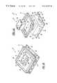
- FIG. 1Ais an exploded perspective view of the electrical block of the present invention
- FIG. 1Bis a perspective view of the present invention assembled
- FIG. 2is a partial perspective view of a mount of the present invention attached to an exterior surface to which siding is attached;
- FIG. 3is an enlarged perspective view of an electrical box of the present invention.
- an electrical block trim assembly 10for use on an exterior surface of a structure is shown.
- the assembly 10has three main components: a mount 12 , a decorative ring 14 , and an electrical box 16 .
- the mount 12has a base 18 , or lower portion, from which a flange 20 extends.
- the flange 20has a plurality of holes 22 adapted to accommodate fasteners which are used to attach the mount 12 to the exterior surface.
- a rectangular housing 24is defined by a plurality of side walls 26 that extend from the base 18 . Although using a rectangular shaped housing simplifies installation of siding around the assembly, it is to be understood that the housing 24 can be any desired shape.
- the housing 24has a top portion 28 disposed between the side walls 26 opposite from the base 18 .
- the top portion 28has an opening 30 and a ledge 32 formed about the opening 30 , which is best shown in FIG. 2 .
- the ledge 32forms a first interlocking member that is used to secure and retain the electrical box 16 to the mount 12 , as described in detail below.
- the housing 24has an outer surface 36 with opposing portions 38 located on opposite side walls 26 , only one of which can be seen in the Figures.
- Each of the portions 38has grooves 40 that are adjacent to one another and that run parallel to the base 18 .
- the decorative ring 14is secured to the mount 12 over the siding 13 to conceal the edges 15 , as best shown in FIG. 2 .
- the decorative ring 14has an rectangular inner perimeter 42 that corresponds to the contour of the housing 24 .
- the inner perimeter 42has opposing protrusions 44 , only one of which can be seen in the Figures, that are aligned with the grooves 40 so that the protrusions 44 interlock with the grooves 40 when the decorative ring 14 is installed over the mount 12 .
- the decorative ring 14may be installed closely to sidings 13 of varying thickness.
- the electrical box 16is secured to the mount 12 during installation of the assembly 10 .
- the electrical box 16has walls 46 with a bottom portion 48 disposed between lower portions of the walls 46 , which form a cavity 47 to accommodate wires and other electrical components.
- At least one knock-out 49is provided on the bottom portion 48 so that the knock-out 49 may be removed and wires may be passed through the resulting opening and into the electrical box cavity 47 .
- the electrical box 16has a second interlocking member that coacts with said first interlocking member and secures said electrical box to the mount 12 .
- the walls 46have an upper portion 52 with a lip 54 that is securely received and retained within the opening 30 and supported by the ledge 32 .
- the upper portion 52has attachment portions 53 with holes 55 to which electrical fixtures may be fastened.
- the upper portion 52has at least one tab 56 that is proximate to the lip 54 .
- the ledge 32forms the first interlocking member and the lip 54 and at least one tab 56 form the second interlocking member.
- the tabs 56secure the electrical box 16 to the mount 12 by receiving the ledge 32 between the lip 54 and the tabs 56 . In this manner, the electrical box 16 is snapped into the opening 30 in the mount 12 .
- the electrical box 16may be retained in the opening 30 using any suitable mechanism. For example, a different interlocking configuration may be used, or an interference fit between the electrical box 16 and opening 30 may be used.
- a hole 60is made in a surface 61 of a structure 62 through which electrical wires 64 are fed.
- the mount 12is secured to the surface 61 by a plurality of fasteners 66 disposed within holes 22 .
- Exterior covering, or siding 13is installed on the surface 61 surrounding a portion of the mount 12 .
- the decorative ring 14(not shown) is installed over the siding 13 and secured to the mount 12 by protrusions 44 and groves 40 .
- the electrical box 16is snapped into the opening 30 so that it is positioned between the exterior surface 61 and the top portion 28 .
- First and second interlocking memberssecure the electrical box 16 to the mount 12 .
- the wires 64are received in the cavity 47 through a removed knock-out 49 .
- the mount 12 and the electrical box 16are separate components of the assembly 10 , they may be constructed from different plastic materials. This enables plastic materials having different characteristics to be used. For example, a plastic suitable for electrical boxes may be used when constructing the electrical box, and a plastic suitable for molding in a wide variety of colors and which has good weatherability may be used for the mount 12 and decorative ring 14 . It is also contemplated by Applicants that the mount 12 and electrical box 16 be provided as a preassembled unit, securely snapped together.
Landscapes
- Engineering & Computer Science (AREA)
- Architecture (AREA)
- Civil Engineering (AREA)
- Structural Engineering (AREA)
- Casings For Electric Apparatus (AREA)
- Connection Or Junction Boxes (AREA)
Abstract
Description
Claims (17)
Priority Applications (3)
| Application Number | Priority Date | Filing Date | Title |
|---|---|---|---|
| US09/342,572US6310287B1 (en) | 1999-06-29 | 1999-06-29 | Electrical block |
| US09/789,695US6359220B2 (en) | 1999-06-29 | 2001-02-21 | Electrical block |
| US09/819,494US6429371B2 (en) | 1999-06-29 | 2001-03-28 | Electrical block |
Applications Claiming Priority (1)
| Application Number | Priority Date | Filing Date | Title |
|---|---|---|---|
| US09/342,572US6310287B1 (en) | 1999-06-29 | 1999-06-29 | Electrical block |
Related Child Applications (2)
| Application Number | Title | Priority Date | Filing Date |
|---|---|---|---|
| US09/789,695ContinuationUS6359220B2 (en) | 1999-06-29 | 2001-02-21 | Electrical block |
| US09/819,494Continuation-In-PartUS6429371B2 (en) | 1999-06-29 | 2001-03-28 | Electrical block |
Publications (1)
| Publication Number | Publication Date |
|---|---|
| US6310287B1true US6310287B1 (en) | 2001-10-30 |
Family
ID=23342405
Family Applications (2)
| Application Number | Title | Priority Date | Filing Date |
|---|---|---|---|
| US09/342,572Expired - LifetimeUS6310287B1 (en) | 1999-06-29 | 1999-06-29 | Electrical block |
| US09/789,695Expired - LifetimeUS6359220B2 (en) | 1999-06-29 | 2001-02-21 | Electrical block |
Family Applications After (1)
| Application Number | Title | Priority Date | Filing Date |
|---|---|---|---|
| US09/789,695Expired - LifetimeUS6359220B2 (en) | 1999-06-29 | 2001-02-21 | Electrical block |
Country Status (1)
| Country | Link |
|---|---|
| US (2) | US6310287B1 (en) |
Cited By (12)
| Publication number | Priority date | Publication date | Assignee | Title |
|---|---|---|---|---|
| US6509524B1 (en)* | 2001-11-07 | 2003-01-21 | Arlington Industries, Inc. | Prepackaged mounting assembly |
| US6723921B2 (en) | 2002-09-24 | 2004-04-20 | Bluegrass Products, Llc | Exterior mounting block for electrical fixtures |
| ES2206055A1 (en)* | 2002-10-25 | 2004-05-01 | Patricia Martin Maza | Base for electrical device has flexible and rigid tabs arranged halfway up to sides of box so that box is enclosed by base without projecting inferiorly from central opening of socket |
| US20040112622A1 (en)* | 2002-09-24 | 2004-06-17 | Michael Vagedes | Exterior mounting block for electrical fixtures |
| US20050055920A1 (en)* | 2003-09-02 | 2005-03-17 | Lajewski Todd M. | Adjustable housing assembly |
| US20050145409A1 (en)* | 2003-12-12 | 2005-07-07 | Yazaki Corporation | Fixing structure of box |
| US20080149792A1 (en)* | 2006-12-21 | 2008-06-26 | Aundrea Nurenberg | Wall mount assembly |
| US20080196938A1 (en)* | 2007-02-16 | 2008-08-21 | Anthony Isaac Funk | Rain shielded box for exiting through siding |
| US7946091B1 (en)* | 2009-04-20 | 2011-05-24 | Crestron Electronics Inc | Post construction wall mounting box |
| US20110312263A1 (en)* | 2010-06-18 | 2011-12-22 | Marc Grandmaison | Louvered vent cover |
| US8572910B2 (en) | 2003-05-09 | 2013-11-05 | Tapco International, Inc. | Cap-on-cap mounting block |
| US20140177148A1 (en)* | 2011-08-03 | 2014-06-26 | Pilz Gmbh & Co. Kg | Operator cabinet with operator terminal |
Families Citing this family (67)
| Publication number | Priority date | Publication date | Assignee | Title |
|---|---|---|---|---|
| US7510153B2 (en)* | 2003-05-09 | 2009-03-31 | Tapco International Corporation | Single piece mounting frame |
| US20070110223A1 (en)* | 2003-10-06 | 2007-05-17 | Pisczak Philip J | Fiber for the home demarcation enclosure |
| US7752814B2 (en)* | 2005-03-28 | 2010-07-13 | Tapco International Corporation | Water deflection apparatus for use with a wall mounting bracket |
| US7516578B2 (en)* | 2005-05-20 | 2009-04-14 | Tapco International Corporation | Exterior siding mounting brackets with a water diversion device |
| US7676993B2 (en)* | 2005-06-13 | 2010-03-16 | Tapco International Corporation | Exterior siding mounting bracket assembly and method of assembly |
| US7566034B2 (en)* | 2005-08-31 | 2009-07-28 | Tapco International Corporation | Bi-directional mounting bracket assembly for exterior siding |
| US7926770B2 (en)* | 2006-01-17 | 2011-04-19 | Tapco International Corporation | Multidirectional mounting bracket assembly for exterior siding |
| US7528322B1 (en)* | 2007-12-28 | 2009-05-05 | Arlington Industries, Inc. | Adjustable electrical box and flange member for installation on a brick or stone wall |
| US8713697B2 (en) | 2008-07-09 | 2014-04-29 | Lennox Manufacturing, Inc. | Apparatus and method for storing event information for an HVAC system |
| US8527096B2 (en) | 2008-10-24 | 2013-09-03 | Lennox Industries Inc. | Programmable controller and a user interface for same |
| US8874815B2 (en) | 2008-10-27 | 2014-10-28 | Lennox Industries, Inc. | Communication protocol system and method for a distributed architecture heating, ventilation and air conditioning network |
| US8560125B2 (en) | 2008-10-27 | 2013-10-15 | Lennox Industries | Communication protocol system and method for a distributed-architecture heating, ventilation and air conditioning network |
| US8655490B2 (en) | 2008-10-27 | 2014-02-18 | Lennox Industries, Inc. | System and method of use for a user interface dashboard of a heating, ventilation and air conditioning network |
| US8564400B2 (en) | 2008-10-27 | 2013-10-22 | Lennox Industries, Inc. | Communication protocol system and method for a distributed-architecture heating, ventilation and air conditioning network |
| US8600559B2 (en) | 2008-10-27 | 2013-12-03 | Lennox Industries Inc. | Method of controlling equipment in a heating, ventilation and air conditioning network |
| US8615326B2 (en) | 2008-10-27 | 2013-12-24 | Lennox Industries Inc. | System and method of use for a user interface dashboard of a heating, ventilation and air conditioning network |
| US8452456B2 (en) | 2008-10-27 | 2013-05-28 | Lennox Industries Inc. | System and method of use for a user interface dashboard of a heating, ventilation and air conditioning network |
| US8661165B2 (en) | 2008-10-27 | 2014-02-25 | Lennox Industries, Inc. | Device abstraction system and method for a distributed architecture heating, ventilation and air conditioning system |
| US8788100B2 (en) | 2008-10-27 | 2014-07-22 | Lennox Industries Inc. | System and method for zoning a distributed-architecture heating, ventilation and air conditioning network |
| US8463443B2 (en) | 2008-10-27 | 2013-06-11 | Lennox Industries, Inc. | Memory recovery scheme and data structure in a heating, ventilation and air conditioning network |
| US20100106329A1 (en)* | 2008-10-27 | 2010-04-29 | Lennox Manufacturing, Inc., A Corporation Of Delaware | Apparatus and method for controlling an environmental conditioning system |
| US8463442B2 (en) | 2008-10-27 | 2013-06-11 | Lennox Industries, Inc. | Alarm and diagnostics system and method for a distributed architecture heating, ventilation and air conditioning network |
| US9325517B2 (en) | 2008-10-27 | 2016-04-26 | Lennox Industries Inc. | Device abstraction system and method for a distributed-architecture heating, ventilation and air conditioning system |
| US8802981B2 (en)* | 2008-10-27 | 2014-08-12 | Lennox Industries Inc. | Flush wall mount thermostat and in-set mounting plate for a heating, ventilation and air conditioning system |
| US8442693B2 (en)* | 2008-10-27 | 2013-05-14 | Lennox Industries, Inc. | System and method of use for a user interface dashboard of a heating, ventilation and air conditioning network |
| US8655491B2 (en) | 2008-10-27 | 2014-02-18 | Lennox Industries Inc. | Alarm and diagnostics system and method for a distributed architecture heating, ventilation and air conditioning network |
| US8543243B2 (en) | 2008-10-27 | 2013-09-24 | Lennox Industries, Inc. | System and method of use for a user interface dashboard of a heating, ventilation and air conditioning network |
| US8798796B2 (en) | 2008-10-27 | 2014-08-05 | Lennox Industries Inc. | General control techniques in a heating, ventilation and air conditioning network |
| US8295981B2 (en) | 2008-10-27 | 2012-10-23 | Lennox Industries Inc. | Device commissioning in a heating, ventilation and air conditioning network |
| US8774210B2 (en) | 2008-10-27 | 2014-07-08 | Lennox Industries, Inc. | Communication protocol system and method for a distributed-architecture heating, ventilation and air conditioning network |
| US8977794B2 (en) | 2008-10-27 | 2015-03-10 | Lennox Industries, Inc. | Communication protocol system and method for a distributed-architecture heating, ventilation and air conditioning network |
| US8855825B2 (en) | 2008-10-27 | 2014-10-07 | Lennox Industries Inc. | Device abstraction system and method for a distributed-architecture heating, ventilation and air conditioning system |
| US9432208B2 (en)* | 2008-10-27 | 2016-08-30 | Lennox Industries Inc. | Device abstraction system and method for a distributed architecture heating, ventilation and air conditioning system |
| US9651925B2 (en) | 2008-10-27 | 2017-05-16 | Lennox Industries Inc. | System and method for zoning a distributed-architecture heating, ventilation and air conditioning network |
| US8548630B2 (en)* | 2008-10-27 | 2013-10-01 | Lennox Industries, Inc. | Alarm and diagnostics system and method for a distributed-architecture heating, ventilation and air conditioning network |
| US8452906B2 (en)* | 2008-10-27 | 2013-05-28 | Lennox Industries, Inc. | Communication protocol system and method for a distributed-architecture heating, ventilation and air conditioning network |
| US8994539B2 (en) | 2008-10-27 | 2015-03-31 | Lennox Industries, Inc. | Alarm and diagnostics system and method for a distributed-architecture heating, ventilation and air conditioning network |
| US8892797B2 (en) | 2008-10-27 | 2014-11-18 | Lennox Industries Inc. | Communication protocol system and method for a distributed-architecture heating, ventilation and air conditioning network |
| US8600558B2 (en) | 2008-10-27 | 2013-12-03 | Lennox Industries Inc. | System recovery in a heating, ventilation and air conditioning network |
| US9632490B2 (en) | 2008-10-27 | 2017-04-25 | Lennox Industries Inc. | System and method for zoning a distributed architecture heating, ventilation and air conditioning network |
| US8762666B2 (en) | 2008-10-27 | 2014-06-24 | Lennox Industries, Inc. | Backup and restoration of operation control data in a heating, ventilation and air conditioning network |
| US8744629B2 (en) | 2008-10-27 | 2014-06-03 | Lennox Industries Inc. | System and method of use for a user interface dashboard of a heating, ventilation and air conditioning network |
| US8694164B2 (en) | 2008-10-27 | 2014-04-08 | Lennox Industries, Inc. | Interactive user guidance interface for a heating, ventilation and air conditioning system |
| US8725298B2 (en) | 2008-10-27 | 2014-05-13 | Lennox Industries, Inc. | Alarm and diagnostics system and method for a distributed architecture heating, ventilation and conditioning network |
| US9678486B2 (en) | 2008-10-27 | 2017-06-13 | Lennox Industries Inc. | Device abstraction system and method for a distributed-architecture heating, ventilation and air conditioning system |
| DE102009046231A1 (en)* | 2009-10-30 | 2011-05-05 | Robert Bosch Gmbh | Electric Brake System, particularly electro-mechanical brake system for motor vehicle, has brake circuit, and control unit for implementation of driver braking demand |
| US8607514B2 (en)* | 2010-04-23 | 2013-12-17 | Andersen Corporation | Window trim system |
| US8963023B2 (en)* | 2010-09-29 | 2015-02-24 | Pakedge Device & Software, Inc. | Enclosure for electronics |
| FR3010110B1 (en) | 2013-09-02 | 2016-02-26 | Legrand France | MASONRY HOUSING AND METHOD FOR INSTALLING SUCH HOUSING |
| US10677484B2 (en) | 2015-05-04 | 2020-06-09 | Johnson Controls Technology Company | User control device and multi-function home control system |
| US11216020B2 (en) | 2015-05-04 | 2022-01-04 | Johnson Controls Tyco IP Holdings LLP | Mountable touch thermostat using transparent screen technology |
| AU2016257459B2 (en) | 2015-05-04 | 2019-04-04 | Johnson Controls Technology Company | Multi-function home control system with control system hub and remote sensors |
| US10760809B2 (en) | 2015-09-11 | 2020-09-01 | Johnson Controls Technology Company | Thermostat with mode settings for multiple zones |
| US10410300B2 (en) | 2015-09-11 | 2019-09-10 | Johnson Controls Technology Company | Thermostat with occupancy detection based on social media event data |
| US10546472B2 (en) | 2015-10-28 | 2020-01-28 | Johnson Controls Technology Company | Thermostat with direction handoff features |
| US10655881B2 (en) | 2015-10-28 | 2020-05-19 | Johnson Controls Technology Company | Thermostat with halo light system and emergency directions |
| US10345781B2 (en) | 2015-10-28 | 2019-07-09 | Johnson Controls Technology Company | Multi-function thermostat with health monitoring features |
| US11277893B2 (en) | 2015-10-28 | 2022-03-15 | Johnson Controls Technology Company | Thermostat with area light system and occupancy sensor |
| US10318266B2 (en) | 2015-11-25 | 2019-06-11 | Johnson Controls Technology Company | Modular multi-function thermostat |
| US10941951B2 (en) | 2016-07-27 | 2021-03-09 | Johnson Controls Technology Company | Systems and methods for temperature and humidity control |
| US10458669B2 (en) | 2017-03-29 | 2019-10-29 | Johnson Controls Technology Company | Thermostat with interactive installation features |
| WO2018191510A1 (en) | 2017-04-14 | 2018-10-18 | Johnson Controls Technology Company | Multi-function thermostat with air quality display |
| US11162698B2 (en) | 2017-04-14 | 2021-11-02 | Johnson Controls Tyco IP Holdings LLP | Thermostat with exhaust fan control for air quality and humidity control |
| US11131474B2 (en) | 2018-03-09 | 2021-09-28 | Johnson Controls Tyco IP Holdings LLP | Thermostat with user interface features |
| US11107390B2 (en) | 2018-12-21 | 2021-08-31 | Johnson Controls Technology Company | Display device with halo |
| USD1023043S1 (en) | 2021-12-02 | 2024-04-16 | PassiveLogic, Inc. | Display screen or portion thereof with a graphical user interface |
| USD1022924S1 (en)* | 2022-02-17 | 2024-04-16 | PassiveLogic, Inc. | Mountable enclosure for a controller device |
Citations (29)
| Publication number | Priority date | Publication date | Assignee | Title |
|---|---|---|---|---|
| US2202147A (en) | 1939-06-03 | 1940-05-28 | Gerriets Fred | Emplacement former |
| US3386606A (en)* | 1964-12-08 | 1968-06-04 | Michael A. Pastrick | Junction box |
| US3906145A (en) | 1973-08-30 | 1975-09-16 | Charles D Carmichael | Mounting system for electrical fixtures |
| US4229916A (en) | 1978-09-29 | 1980-10-28 | White Robert W | Building panel |
| US4327841A (en) | 1980-10-17 | 1982-05-04 | Joseph Wimberly | Insulated outlet cover |
| US4726152A (en) | 1986-11-24 | 1988-02-23 | Vagedes Industries, Inc. | Bracket for mounting a fixture on a wall |
| US4854093A (en) | 1988-09-02 | 1989-08-08 | Kellom Gary J | Fixture mount |
| US4874904A (en)* | 1988-04-14 | 1989-10-17 | Brintec Corporation | Fiber optic faceplate assembly |
| US4875318A (en) | 1988-05-10 | 1989-10-24 | Tapco Products Company, Inc. | Plastic building product |
| US5000409A (en) | 1989-12-04 | 1991-03-19 | Tapco Products Company, Inc. | One piece wall mounting bracket |
| US5042673A (en)* | 1989-06-22 | 1991-08-27 | Mcshane William J | Electric box extension |
| US5117996A (en)* | 1989-06-22 | 1992-06-02 | Mcshane William J | Electrical box extension |
| US5133165A (en) | 1991-03-22 | 1992-07-28 | Taurus Safety Products, Inc. | Outlet cover u-trim |
| USD343825S (en) | 1991-08-21 | 1994-02-01 | Timothy Enderby | Combined electrical box and mounting block therefor |
| US5326060A (en) | 1992-06-25 | 1994-07-05 | Mid-America Building Products Corporation | Plastic building wall mount assembly |
| US5397093A (en) | 1992-06-25 | 1995-03-14 | Mid-America Building Products Corporation | Wall mounting assembly |
| US5478032A (en)* | 1994-06-15 | 1995-12-26 | The Whitaker Corporation | Retrofit drywall mounting frame |
| US5522577A (en)* | 1994-06-13 | 1996-06-04 | The Lamson & Sessions Co. | Ceiling fan support arrangement |
| US5578791A (en) | 1994-05-12 | 1996-11-26 | Bosse, Jr.; John J. | Combined wall mount and electrical outlet box |
| US5598670A (en) | 1994-08-16 | 1997-02-04 | Thermo Plastic Works, Inc. | Wall mounting system for electrical devices |
| US5659151A (en)* | 1994-09-09 | 1997-08-19 | The Whitaker Corporation | Wire management knockout closure for electrical boxes |
| US5668350A (en)* | 1995-10-20 | 1997-09-16 | Yazaki Corporation | Electric connection box |
| US5722208A (en) | 1994-08-16 | 1998-03-03 | Thermo Plastic Works, Inc. | Wall mounting system for electrical devices |
| US5804764A (en)* | 1995-03-24 | 1998-09-08 | Arlington Industries, Inc. | Two-piece siding box |
| US5920033A (en) | 1994-05-12 | 1999-07-06 | Bosse, Jr.; John J. | Combined wall mount and electrical outlet box |
| US5952610A (en) | 1994-05-12 | 1999-09-14 | Bosse, Jr.; John J. | Combined wall mount and electrical outlet box |
| US6005188A (en)* | 1997-03-12 | 1999-12-21 | Krone Ag | Stationary housing with wall elements made of plastic |
| US6041956A (en)* | 1998-11-10 | 2000-03-28 | Kao; Ken | Network device case |
| USD422266S (en)* | 1999-07-13 | 2000-04-04 | The Lamson & Sessions Co. | Electrical box |
Family Cites Families (6)
| Publication number | Priority date | Publication date | Assignee | Title |
|---|---|---|---|---|
| US343825A (en) | 1886-06-15 | Stephen j | ||
| GB735240A (en)* | 1952-11-14 | 1955-08-17 | Simplex Electric Co Ltd | Improvements relating to mounting blocks for electrical accessories |
| US5084596A (en)* | 1990-06-04 | 1992-01-28 | The Lamson & Sessions Co. | Electrical box |
| US5831212A (en)* | 1995-06-12 | 1998-11-03 | Thomas & Betts Corporation | Electrical junction box for a poured concrete floor |
| FR2741755B1 (en)* | 1995-11-23 | 1998-02-06 | Legrand Sa | SUPPORT DEVICE FOR EQUIPMENT, IN PARTICULAR FOR ELECTRICAL EQUIPMENT, TO BE MOUNTED ON A CHUTE BODY |
| US6107567A (en)* | 1998-07-22 | 2000-08-22 | Reliance Electric Technologies, Llc | Water-resistant conduit box for large electric motor, mountable in a plurality of orientations |
- 1999
- 1999-06-29USUS09/342,572patent/US6310287B1/ennot_activeExpired - Lifetime
- 2001
- 2001-02-21USUS09/789,695patent/US6359220B2/ennot_activeExpired - Lifetime
Patent Citations (30)
| Publication number | Priority date | Publication date | Assignee | Title |
|---|---|---|---|---|
| US2202147A (en) | 1939-06-03 | 1940-05-28 | Gerriets Fred | Emplacement former |
| US3386606A (en)* | 1964-12-08 | 1968-06-04 | Michael A. Pastrick | Junction box |
| US3906145A (en) | 1973-08-30 | 1975-09-16 | Charles D Carmichael | Mounting system for electrical fixtures |
| US4229916A (en) | 1978-09-29 | 1980-10-28 | White Robert W | Building panel |
| US4327841A (en) | 1980-10-17 | 1982-05-04 | Joseph Wimberly | Insulated outlet cover |
| US4726152A (en) | 1986-11-24 | 1988-02-23 | Vagedes Industries, Inc. | Bracket for mounting a fixture on a wall |
| US4874904A (en)* | 1988-04-14 | 1989-10-17 | Brintec Corporation | Fiber optic faceplate assembly |
| US4920708A (en) | 1988-05-10 | 1990-05-01 | Tapco Products Company, Inc. | Wall mounting assembly |
| US4875318A (en) | 1988-05-10 | 1989-10-24 | Tapco Products Company, Inc. | Plastic building product |
| US4854093A (en) | 1988-09-02 | 1989-08-08 | Kellom Gary J | Fixture mount |
| US5042673A (en)* | 1989-06-22 | 1991-08-27 | Mcshane William J | Electric box extension |
| US5117996A (en)* | 1989-06-22 | 1992-06-02 | Mcshane William J | Electrical box extension |
| US5000409A (en) | 1989-12-04 | 1991-03-19 | Tapco Products Company, Inc. | One piece wall mounting bracket |
| US5133165A (en) | 1991-03-22 | 1992-07-28 | Taurus Safety Products, Inc. | Outlet cover u-trim |
| USD343825S (en) | 1991-08-21 | 1994-02-01 | Timothy Enderby | Combined electrical box and mounting block therefor |
| US5397093A (en) | 1992-06-25 | 1995-03-14 | Mid-America Building Products Corporation | Wall mounting assembly |
| US5326060A (en) | 1992-06-25 | 1994-07-05 | Mid-America Building Products Corporation | Plastic building wall mount assembly |
| US5920033A (en) | 1994-05-12 | 1999-07-06 | Bosse, Jr.; John J. | Combined wall mount and electrical outlet box |
| US5578791A (en) | 1994-05-12 | 1996-11-26 | Bosse, Jr.; John J. | Combined wall mount and electrical outlet box |
| US5952610A (en) | 1994-05-12 | 1999-09-14 | Bosse, Jr.; John J. | Combined wall mount and electrical outlet box |
| US5522577A (en)* | 1994-06-13 | 1996-06-04 | The Lamson & Sessions Co. | Ceiling fan support arrangement |
| US5478032A (en)* | 1994-06-15 | 1995-12-26 | The Whitaker Corporation | Retrofit drywall mounting frame |
| US5598670A (en) | 1994-08-16 | 1997-02-04 | Thermo Plastic Works, Inc. | Wall mounting system for electrical devices |
| US5722208A (en) | 1994-08-16 | 1998-03-03 | Thermo Plastic Works, Inc. | Wall mounting system for electrical devices |
| US5659151A (en)* | 1994-09-09 | 1997-08-19 | The Whitaker Corporation | Wire management knockout closure for electrical boxes |
| US5804764A (en)* | 1995-03-24 | 1998-09-08 | Arlington Industries, Inc. | Two-piece siding box |
| US5668350A (en)* | 1995-10-20 | 1997-09-16 | Yazaki Corporation | Electric connection box |
| US6005188A (en)* | 1997-03-12 | 1999-12-21 | Krone Ag | Stationary housing with wall elements made of plastic |
| US6041956A (en)* | 1998-11-10 | 2000-03-28 | Kao; Ken | Network device case |
| USD422266S (en)* | 1999-07-13 | 2000-04-04 | The Lamson & Sessions Co. | Electrical box |
Cited By (24)
| Publication number | Priority date | Publication date | Assignee | Title |
|---|---|---|---|---|
| US6509524B1 (en)* | 2001-11-07 | 2003-01-21 | Arlington Industries, Inc. | Prepackaged mounting assembly |
| US6723921B2 (en) | 2002-09-24 | 2004-04-20 | Bluegrass Products, Llc | Exterior mounting block for electrical fixtures |
| US20040112622A1 (en)* | 2002-09-24 | 2004-06-17 | Michael Vagedes | Exterior mounting block for electrical fixtures |
| US6825414B2 (en) | 2002-09-24 | 2004-11-30 | Bluegrass Products, L.L.C. | Exterior mounting block for electrical fixtures |
| ES2206055A1 (en)* | 2002-10-25 | 2004-05-01 | Patricia Martin Maza | Base for electrical device has flexible and rigid tabs arranged halfway up to sides of box so that box is enclosed by base without projecting inferiorly from central opening of socket |
| ES2206055B1 (en)* | 2002-10-25 | 2005-03-01 | Patricia Martin Maza | BASE FOR ELECTRICAL DEVICES. |
| US8572910B2 (en) | 2003-05-09 | 2013-11-05 | Tapco International, Inc. | Cap-on-cap mounting block |
| US20090255191A1 (en)* | 2003-09-02 | 2009-10-15 | Tapco International Corporation | Adjustable housing assembly |
| US20050055920A1 (en)* | 2003-09-02 | 2005-03-17 | Lajewski Todd M. | Adjustable housing assembly |
| US8225563B2 (en) | 2003-09-02 | 2012-07-24 | Tapco International Corporation | Adjustable housing assembly |
| US20110225900A1 (en)* | 2003-09-02 | 2011-09-22 | Tapco International Corporation | Adjustable housing assembly |
| US7549258B2 (en) | 2003-09-02 | 2009-06-23 | Tapco International Corporation | Adjustable housing assembly |
| US7950195B2 (en) | 2003-09-02 | 2011-05-31 | Tapco International Corporation | Adjustable housing assembly |
| US20050145409A1 (en)* | 2003-12-12 | 2005-07-07 | Yazaki Corporation | Fixing structure of box |
| US7049509B2 (en)* | 2003-12-12 | 2006-05-23 | Yazaki Corporation | Fixing structure of box |
| US7946545B2 (en)* | 2006-12-21 | 2011-05-24 | Tapco International Corporation | Wall mount assembly |
| US20080149792A1 (en)* | 2006-12-21 | 2008-06-26 | Aundrea Nurenberg | Wall mount assembly |
| US7875798B2 (en) | 2007-02-16 | 2011-01-25 | Anthony Isaac Funk | Rain shielded box for exiting through siding |
| US20080196938A1 (en)* | 2007-02-16 | 2008-08-21 | Anthony Isaac Funk | Rain shielded box for exiting through siding |
| US7946091B1 (en)* | 2009-04-20 | 2011-05-24 | Crestron Electronics Inc | Post construction wall mounting box |
| US20110312263A1 (en)* | 2010-06-18 | 2011-12-22 | Marc Grandmaison | Louvered vent cover |
| US8784168B2 (en)* | 2010-06-18 | 2014-07-22 | Imperial Sheet Metal Ltd. | Louvered vent cover |
| US20140177148A1 (en)* | 2011-08-03 | 2014-06-26 | Pilz Gmbh & Co. Kg | Operator cabinet with operator terminal |
| US9232675B2 (en)* | 2011-08-03 | 2016-01-05 | Pilz Gmbh & Co. Kg | Operator cabinet with operator terminal |
Also Published As
| Publication number | Publication date |
|---|---|
| US6359220B2 (en) | 2002-03-19 |
| US20010015281A1 (en) | 2001-08-23 |
Similar Documents
| Publication | Publication Date | Title |
|---|---|---|
| US6310287B1 (en) | Electrical block | |
| US6429371B2 (en) | Electrical block | |
| US5073681A (en) | Two-piece wall plate for electrical device | |
| US6723921B2 (en) | Exterior mounting block for electrical fixtures | |
| CA1062169A (en) | Speaker mounting | |
| US6123438A (en) | Insulation shield for recessed downlighting fixtures | |
| USRE38881E1 (en) | Plastic building wall mount assembly | |
| US5375728A (en) | Assembly for covering a wall-mounted electrical outlet | |
| US5918431A (en) | Split-block recess mount apparatus | |
| US4726152A (en) | Bracket for mounting a fixture on a wall | |
| US20050086736A1 (en) | Shower surround structure | |
| CA2442238C (en) | Exterior mounting block for electrical fixtures | |
| US5939671A (en) | Ceiling medallion assembly | |
| US5689924A (en) | Construction of modular office panel systems | |
| CA2129595A1 (en) | Plastic Electrical Box for Installation in Poured Concrete | |
| US5356311A (en) | Network wall plate | |
| US5975853A (en) | Cover for a ceiling aperture | |
| US6774304B1 (en) | Siding box assembly | |
| US20090126968A1 (en) | Screwless wall-plate | |
| EP0890796B1 (en) | Cooktop | |
| US6168285B1 (en) | Universal, light fixture/ceiling fan recessed mounting device | |
| US20090194312A1 (en) | Convertible cover plate for a floor box | |
| US20060278775A1 (en) | Adjustable mount assembly | |
| US4842155A (en) | Mounting apparatus for electrical devices | |
| JP3459555B2 (en) | How to attach the chair leg base cover |
Legal Events
| Date | Code | Title | Description |
|---|---|---|---|
| AS | Assignment | Owner name:TAPCO INTERNATIONAL CORPORATION, MICHIGAN Free format text:ASSIGNMENT OF ASSIGNORS INTEREST;ASSIGNORS:SCHIEDEGGER, CHARLES E.;NURENBERG, AUNDREA;ALLEN, CLYDE G.;AND OTHERS;REEL/FRAME:010093/0373 Effective date:19990624 | |
| STCF | Information on status: patent grant | Free format text:PATENTED CASE | |
| AS | Assignment | Owner name:MORGAN STANLEY & CO. INCORPORATED, NEW YORK Free format text:SECURITY AGREEMENT;ASSIGNORS:HEADWATERS INCORPORATED;ACM BLOCK & BRICK GENERAL, INC.;ACM BLOCK & BRICK PARTNER, LLC,;AND OTHERS;REEL/FRAME:015896/0667 Effective date:20040908 | |
| AS | Assignment | Owner name:MORGAN STANLEY & CO. INCORPORATED, NEW YORK Free format text:SECOND LIEN IP SECURITY AGREEMENT;ASSIGNORS:HEADWATERS INCORPORATED;ACM BLOCK & BRICK GENERAL, INC.;ACM BLOCK & BRICK PARTNER, LLC;AND OTHERS;REEL/FRAME:015908/0816 Effective date:20040908 | |
| FPAY | Fee payment | Year of fee payment:4 | |
| FPAY | Fee payment | Year of fee payment:8 | |
| AS | Assignment | Owner name:HEADWATER RESOURCES, INC. (SUCCESSOR TO JTM INDUST Free format text:RELEASE OF SECURITY AGREEMENT;ASSIGNOR:MORGAN STANLEY & CO. INCORPORATED;REEL/FRAME:023449/0740 Effective date:20091027 Owner name:HEADWATERS INCORPORATED, UTAH Free format text:RELEASE OF SECURITY AGREEMENT;ASSIGNOR:MORGAN STANLEY & CO. INCORPORATED;REEL/FRAME:023438/0778 Effective date:20091027 Owner name:TAPCO INTERNATIONAL CORPORATION (SUCCESSOR TO MID Free format text:RELEASE OF SECURITY AGREEMENT;ASSIGNOR:MORGAN STANLEY & CO. INCORPORATED;REEL/FRAME:023449/0740 Effective date:20091027 Owner name:TAPCO INTERNATIONAL CORPORATION, MICHIGAN Free format text:RELEASE OF SECURITY AGREEMENT;ASSIGNOR:MORGAN STANLEY & CO. INCORPORATED;REEL/FRAME:023449/0740 Effective date:20091027 Owner name:CROZZOLI, GUALTIERO, ITALY Free format text:RELEASE OF SECURITY AGREEMENT;ASSIGNOR:MORGAN STANLEY & CO. INCORPORATED;REEL/FRAME:023449/0740 Effective date:20091027 Owner name:HEADWATERS RESOURCES, INC., UTAH Free format text:RELEASE OF SECURITY AGREEMENT;ASSIGNOR:MORGAN STANLEY & CO. INCORPORATED;REEL/FRAME:023438/0778 Effective date:20091027 Owner name:TAPCO INTERNATIONAL CORPORATION, MICHIGAN Free format text:RELEASE OF SECURITY AGREEMENT;ASSIGNOR:MORGAN STANLEY & CO. INCORPORATED;REEL/FRAME:023438/0778 Effective date:20091027 Owner name:HEADWATERS CTL., LLC (SUCCESSOR TO HYDROCARBON TEC Free format text:RELEASE OF SECURITY AGREEMENT;ASSIGNOR:MORGAN STANLEY & CO. INCORPORATED;REEL/FRAME:023449/0740 Effective date:20091027 Owner name:CURTIS-WRIGHT FLOW CONTROL CORPORATION, NEW JERSEY Free format text:RELEASE OF SECURITY AGREEMENT;ASSIGNOR:MORGAN STANLEY & CO. INCORPORATED;REEL/FRAME:023449/0740 Effective date:20091027 Owner name:CURTIS-WRIGHT FLOW CONTROL CORPORATION, NEW JERSEY Free format text:RELEASE OF SECURITY AGREEMENT;ASSIGNOR:MORGAN STANLEY & CO. INCORPORATED;REEL/FRAME:023438/0778 Effective date:20091027 Owner name:TAPCO INTERNATIONAL CORPORATION (SUCCESSOR TO TAPC Free format text:RELEASE OF SECURITY AGREEMENT;ASSIGNOR:MORGAN STANLEY & CO. INCORPORATED;REEL/FRAME:023438/0778 Effective date:20091027 Owner name:TAPCO INTERNATIONAL CORPORATON (SUCCESSOR TO TAPCO Free format text:RELEASE OF SECURITY AGREEMENT;ASSIGNOR:MORGAN STANLEY & CO. INCORPORATED;REEL/FRAME:023449/0740 Effective date:20091027 Owner name:HEADWATERS RESOURCES, INC. (SUCCESSOR TO JTM INDUS Free format text:RELEASE OF SECURITY AGREEMENT;ASSIGNOR:MORGAN STANLEY & CO. INCORPORATED;REEL/FRAME:023438/0778 Effective date:20091027 Owner name:CROZZOLI, GUALTIERO, ITALY Free format text:RELEASE OF SECURITY AGREEMENT;ASSIGNOR:MORGAN STANLEY & CO. INCORPORATED;REEL/FRAME:023438/0778 Effective date:20091027 Owner name:HEADWATERS CTL, LLC (SUCCESSOR TO HYDROCARBON TECH Free format text:RELEASE OF SECURITY AGREEMENT;ASSIGNOR:MORGAN STANLEY & CO. INCORPORATED;REEL/FRAME:023438/0778 Effective date:20091027 Owner name:HEADWATERS TECHNOLOGY INNOVATION GROUP, INC. (SUCC Free format text:RELEASE OF SECURITY AGREEMENT;ASSIGNOR:MORGAN STANLEY & CO. INCORPORATED;REEL/FRAME:023438/0778 Effective date:20091027 Owner name:HEADWATERS INCORPORATED, UTAH Free format text:RELEASE OF SECURITY AGREEMENT;ASSIGNOR:MORGAN STANLEY & CO. INCORPORATED;REEL/FRAME:023449/0740 Effective date:20091027 Owner name:HEADWATERS RESOURCES, INC., UTAH Free format text:RELEASE OF SECURITY AGREEMENT;ASSIGNOR:MORGAN STANLEY & CO. INCORPORATED;REEL/FRAME:023449/0740 Effective date:20091027 Owner name:TAPCO INTERNATIONAL CORPORATION (SUCCESSOR TO MID Free format text:RELEASE OF SECURITY AGREEMENT;ASSIGNOR:MORGAN STANLEY & CO. INCORPORATED;REEL/FRAME:023438/0778 Effective date:20091027 Owner name:HEADWATERS TECHNOLOGY INNOVATION GROUP, INC. (SUCC Free format text:RELEASE OF SECURITY AGREEMENT;ASSIGNOR:MORGAN STANLEY & CO. INCORPORATED;REEL/FRAME:023449/0740 Effective date:20091027 | |
| AS | Assignment | Owner name:BANK OF AMERICA, N.A., CALIFORNIA Free format text:SECURITY AGREEMENT;ASSIGNORS:HEADWATERS INCORPORATED;TAPCO INTERNATIONAL CORPORATION;HEADWATERS RESOURCES, INC.;REEL/FRAME:023449/0470 Effective date:20091027 Owner name:BANK OF AMERICA, N.A.,CALIFORNIA Free format text:SECURITY AGREEMENT;ASSIGNORS:HEADWATERS INCORPORATED;TAPCO INTERNATIONAL CORPORATION;HEADWATERS RESOURCES, INC.;REEL/FRAME:023449/0470 Effective date:20091027 | |
| AS | Assignment | Owner name:WILMINGTON TRUST FSB, AS COLLATERAL AGENT,MINNESOT Free format text:SECURITY AGREEMENT;ASSIGNORS:HEADWATERS INCORPORATED, A DELAWARE CORPORATION;HEADWATERS CTL, LLC, A UTAH LIMITED LIABILITY COMPANY, USA;HEADWATERS HEAVY OIL, LLC, A UTAH LIMITED LIABILITY COMPANY, USA;AND OTHERS;REEL/FRAME:023699/0452 Effective date:20091027 Owner name:WILMINGTON TRUST FSB, AS COLLATERAL AGENT, MINNESO Free format text:SECURITY AGREEMENT;ASSIGNORS:HEADWATERS INCORPORATED, A DELAWARE CORPORATION;HEADWATERS CTL, LLC, A UTAH LIMITED LIABILITY COMPANY, USA;HEADWATERS HEAVY OIL, LLC, A UTAH LIMITED LIABILITY COMPANY, USA;AND OTHERS;REEL/FRAME:023699/0452 Effective date:20091027 Owner name:WILMINGTON TRUST FSB, AS COLLATERAL AGENT, MINNESOTA Free format text:SECURITY AGREEMENT;ASSIGNORS:HEADWATERS INCORPORATED, A DELAWARE CORPORATION;HEADWATERS CTL, LLC, A UTAH LIMITED LIABILITY COMPANY, USA;HEADWATERS HEAVY OIL, LLC, A UTAH LIMITED LIABILITY COMPANY, USA;AND OTHERS;REEL/FRAME:023699/0452 Effective date:20091027 | |
| FPAY | Fee payment | Year of fee payment:12 | |
| AS | Assignment | Owner name:HEADWATERS HEAVY OIL, LLC, A UTAH CORPORATION, UTAH Free format text:PATENT RELEASE (REEL:23699/FRAME:0452);ASSIGNOR:WILMINGTON TRUST, NATIONAL ASSOCIATION, AS COLLATERAL AGENT;REEL/FRAME:035306/0558 Effective date:20150324 Owner name:HEADWATERS TECHNOLOGY INNOVATION GROUP, INC., A UTAH CORPORATION, UTAH Free format text:PATENT RELEASE (REEL:23699/FRAME:0452);ASSIGNOR:WILMINGTON TRUST, NATIONAL ASSOCIATION, AS COLLATERAL AGENT;REEL/FRAME:035306/0558 Effective date:20150324 Owner name:TAPCO INTERNATIONAL CORPORATION, A MICHIGAN CORPORATION, UTAH Free format text:PATENT RELEASE (REEL:23699/FRAME:0452);ASSIGNOR:WILMINGTON TRUST, NATIONAL ASSOCIATION, AS COLLATERAL AGENT;REEL/FRAME:035306/0558 Effective date:20150324 Owner name:HEADWATERS RESOURCES, INC., A UTAH CORPORATION, UTAH Free format text:PATENT RELEASE (REEL:23699/FRAME:0452);ASSIGNOR:WILMINGTON TRUST, NATIONAL ASSOCIATION, AS COLLATERAL AGENT;REEL/FRAME:035306/0558 Effective date:20150324 Owner name:HEADWATERS TECHNOLOGY INNOVATION GROUP, INC., A UT Free format text:PATENT RELEASE (REEL:23699/FRAME:0452);ASSIGNOR:WILMINGTON TRUST, NATIONAL ASSOCIATION, AS COLLATERAL AGENT;REEL/FRAME:035306/0558 Effective date:20150324 Owner name:HEADWATERS HEAVY OIL, LLC, A UTAH CORPORATION, UTA Free format text:PATENT RELEASE (REEL:23699/FRAME:0452);ASSIGNOR:WILMINGTON TRUST, NATIONAL ASSOCIATION, AS COLLATERAL AGENT;REEL/FRAME:035306/0558 Effective date:20150324 Owner name:HEADWATERS RESOURCES, INC., A UTAH CORPORATION, UT Free format text:PATENT RELEASE (REEL:23699/FRAME:0452);ASSIGNOR:WILMINGTON TRUST, NATIONAL ASSOCIATION, AS COLLATERAL AGENT;REEL/FRAME:035306/0558 Effective date:20150324 Owner name:HEADWATERS INCORPORATED, AS GRANTOR, UTAH Free format text:PATENT RELEASE (REEL:23699/FRAME:0452);ASSIGNOR:WILMINGTON TRUST, NATIONAL ASSOCIATION, AS COLLATERAL AGENT;REEL/FRAME:035306/0558 Effective date:20150324 Owner name:TAPCO INTERNATIONAL CORPORATION, A MICHIGAN CORPOR Free format text:PATENT RELEASE (REEL:23699/FRAME:0452);ASSIGNOR:WILMINGTON TRUST, NATIONAL ASSOCIATION, AS COLLATERAL AGENT;REEL/FRAME:035306/0558 Effective date:20150324 | |
| AS | Assignment | Owner name:DEUTSCHE BANK AG NEW YORK BRANCH, AS ADMINISTRATIV Free format text:SECURITY AGREEMENT;ASSIGNORS:HEADWATERS INCORPORATED, AS GRANTOR;TAPCO INTERNATIONAL CORPORATION, A MICHIGAN CORPORATION;HEADWATERS HEAVY OIL, LLC, A UTAH CORPORATION;AND OTHERS;REEL/FRAME:035327/0462 Effective date:20150324 Owner name:DEUTSCHE BANK AG NEW YORK BRANCH, AS ADMINISTRATIVE AGENT, NEW YORK Free format text:SECURITY AGREEMENT;ASSIGNORS:HEADWATERS INCORPORATED, AS GRANTOR;TAPCO INTERNATIONAL CORPORATION, A MICHIGAN CORPORATION;HEADWATERS HEAVY OIL, LLC, A UTAH CORPORATION;AND OTHERS;REEL/FRAME:035327/0462 Effective date:20150324 | |
| AS | Assignment | Owner name:HEADWATERS RESOURCES, INC., UTAH Free format text:RELEASE BY SECURED PARTY;ASSIGNOR:DEUTSCHE BANK AG NEW YORK BRANCH;REEL/FRAME:042422/0640 Effective date:20170508 Owner name:HEADWATERS HEAVY OIL, LLC, UTAH Free format text:RELEASE BY SECURED PARTY;ASSIGNOR:DEUTSCHE BANK AG NEW YORK BRANCH;REEL/FRAME:042422/0640 Effective date:20170508 Owner name:TAPCO INTERNATIONAL CORPORATION, UTAH Free format text:RELEASE BY SECURED PARTY;ASSIGNOR:DEUTSCHE BANK AG NEW YORK BRANCH;REEL/FRAME:042422/0640 Effective date:20170508 Owner name:HEADWATERS INCORPORATED, UTAH Free format text:RELEASE BY SECURED PARTY;ASSIGNOR:DEUTSCHE BANK AG NEW YORK BRANCH;REEL/FRAME:042422/0640 Effective date:20170508 | |
| AS | Assignment | Owner name:HEADWATERS RESOURCES, LLC (FKA HEADWATERS RESOURCE Free format text:RELEASE BY SECURED PARTY;ASSIGNOR:BANK OF AMERICA, N.A.;REEL/FRAME:042446/0199 Effective date:20170508 Owner name:TAPCO INTERNATIONAL CORPORATION, UTAH Free format text:RELEASE BY SECURED PARTY;ASSIGNOR:BANK OF AMERICA, N.A.;REEL/FRAME:042446/0199 Effective date:20170508 Owner name:HEADWATERS INCORPORATED, UTAH Free format text:RELEASE BY SECURED PARTY;ASSIGNOR:BANK OF AMERICA, N.A.;REEL/FRAME:042446/0199 Effective date:20170508 | |
| AS | Assignment | Owner name:BORAL BUILDING PRODUCTS INC., MICHIGAN Free format text:CHANGE OF NAME;ASSIGNOR:TAPCO INTERNATIONAL CORPORATION;REEL/FRAME:050261/0206 Effective date:20180701 |