US6308278B1 - Supplying standby voltage to memory and wakeup circuitry to wake a computer from a low power mode - Google Patents
Supplying standby voltage to memory and wakeup circuitry to wake a computer from a low power modeDownload PDFInfo
- Publication number
- US6308278B1 US6308278B1US09/001,102US110297AUS6308278B1US 6308278 B1US6308278 B1US 6308278B1US 110297 AUS110297 AUS 110297AUS 6308278 B1US6308278 B1US 6308278B1
- Authority
- US
- United States
- Prior art keywords
- computer
- power
- normal
- standby
- voltage
- Prior art date
- Legal status (The legal status is an assumption and is not a legal conclusion. Google has not performed a legal analysis and makes no representation as to the accuracy of the status listed.)
- Expired - Lifetime
Links
Images


Classifications
- G—PHYSICS
- G06—COMPUTING OR CALCULATING; COUNTING
- G06F—ELECTRIC DIGITAL DATA PROCESSING
- G06F1/00—Details not covered by groups G06F3/00 - G06F13/00 and G06F21/00
- G06F1/26—Power supply means, e.g. regulation thereof
- G06F1/263—Arrangements for using multiple switchable power supplies, e.g. battery and AC
- G—PHYSICS
- G06—COMPUTING OR CALCULATING; COUNTING
- G06F—ELECTRIC DIGITAL DATA PROCESSING
- G06F1/00—Details not covered by groups G06F3/00 - G06F13/00 and G06F21/00
- G06F1/26—Power supply means, e.g. regulation thereof
- G06F1/32—Means for saving power
- G06F1/3203—Power management, i.e. event-based initiation of a power-saving mode
- G06F1/3206—Monitoring of events, devices or parameters that trigger a change in power modality
- G06F1/3209—Monitoring remote activity, e.g. over telephone lines or network connections
- G—PHYSICS
- G06—COMPUTING OR CALCULATING; COUNTING
- G06F—ELECTRIC DIGITAL DATA PROCESSING
- G06F1/00—Details not covered by groups G06F3/00 - G06F13/00 and G06F21/00
- G06F1/26—Power supply means, e.g. regulation thereof
- G06F1/32—Means for saving power
- G06F1/3203—Power management, i.e. event-based initiation of a power-saving mode
- G06F1/3206—Monitoring of events, devices or parameters that trigger a change in power modality
- G06F1/3215—Monitoring of peripheral devices
Definitions
- the present inventionrelates to power conservation within a digital computer, and more particularly, to a power management system for a desktop computer.
- Reducing the power consumed by a computerhas two significant advantages: 1) less power must be supplied to the computer; and 2) less heat must be dissipated by the computer into the surrounding environment.
- a warm daymany businesses pay both for the electricity to power their computers and for the electricity for the air conditioning to cool their buildings.
- PCSdesktop personal computers
- FIG. 1illustrates a block diagram of a typical computer, such as a PC.
- PC 110includes a host processor 112 connected to a local bus 114 .
- Host processor 112may be, for example, a Pentium® processor available from Intel Corp. for executing instructions and controlling operation of the PC.
- DRAMdynamic random access memory
- a Peripheral Component Interface (PCI) bus 124is connected to a magnetic hard disk drive (HDD) 134 , a graphics card 136 , and one or more PCI expansion slots 128 .
- a local bus/PCI bridge 126operates as an interface or bridge for local bus signals and PCI bus signals.
- PC 110also includes an Industry Standard Architecture (ISA) bus 140 .
- the ISA bus 140is connected to the PCI bus via a PCI/ISA bridge 132 .
- PCI/ISA bridge 140is the 8237AB PCI-TO-ISA/IDE Xcelerator (PIIX4), available from Intel Corp.
- the ISA busis connected to an audio card 144 , one or more ISA expansion slots 138 , and a Super input/output (I/O) chip 146 .
- the Super I/O chipincludes a keyboard and mouse controller, a floppy drive controller, two serial ports, a parallel port, and an infra-red (IR) port.
- IRinfra-red
- Super I/O chip 146uses various I/O devices in the PC, such as a keyboard and mouse, floppy drives, printers, and the like.
- a Super I/O chipis the FDC37C67x 100 Pin Enhanced Super I/O Controller With Fast IR, available from Standard Microsystems Corp.
- the PIIX4 chip, the Super I/O chip and the system softwarecan operate to place the computer into a sleep or power saving mode in which power is conserved.
- a commandcan be provided to halt the host processor 112 to conserve power.
- the standard operating voltages(3.3V, 5.0V at 10-13 A) are still provided from the power supply to the motherboard and various peripheral components to allow the components to detect activity (e.g., keyboard or mouse movement, LAN activity) and then “wake” the computer to resume normal operation.
- activitye.g., keyboard or mouse movement, LAN activity
- a significant amount of powertypically 30-40 Watts
- the power supplyWhen the power supply is plugged in and the external mechanical power switch is not depressed, the power supply typically provides only about 0.1 A of trickle current only to a portion of the PIIX4 chip to allow the PIIX4 chip to detect the depression of the external mechanical power switch.
- the PIIX4 chip and the system softwareoperate to reestablish normal power and cold boot the computer when the PIIX4 chip detects the depression of the external power switch.
- poweris not applied to any other portion or component of the computer, it is impossible to “wake” the computer from this mechanical Off state. Therefore, a need exists for an improved power management system that allows a peripheral or component to wake the computer from a power saving mode while consuming less power.
- the power management system of the present inventionovercomes the disadvantages of the prior art by supplying only a standby voltage to a portion of the computer that may be involved in waking the computer. Computer activity is detected, and then a wake signal is generated in response to the computer activity. The normal voltage is supplied to the computer in response to the wake signal.
- FIG. 1illustrates a block diagram of a computer.
- FIG. 2illustrates a block diagram of a portion of a computer including an improved power management system according to an embodiment of the present invention.
- FIG. 3is a circuit diagram of a computer interface for a keyboard and a mouse according to an embodiment of the computer of FIG. 2 .
- FIG. 4is a circuit diagram of a computer interface for a keyboard and a mouse according to another embodiment of the computer of FIG. 2 .
- FIG. 5is a flow chart illustrating a method of waking the computer of FIG. 2 according to an embodiment of the present invention.
- FIG. 6illustrates a block diagram of a portion of a computer including an improved power management system according to an embodiment of the present invention.
- FIG. 7illustrates a block diagram of a portion of a computer including an improved power management system according to another embodiment of the present invention.
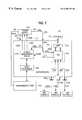
- FIG. 2illustrates a block diagram of a portion of a computer 200 including an improved power management system according to an embodiment of the present invention.
- a motherboard 212is illustrated that includes several components thereon, including a host processor 204 for decoding and executing software and controlling the operation of the computer.
- Host processor 204may be a Pentium® processor or the like available from Intel Corp.
- a dynamic random access memory (or DRAM) card 206is coupled to the motherboard 212 via line 207 .
- a dual mode power supply 210is coupled to motherboard 212 via line 230 , lines 232 A-C and line 234 and supplies multiple voltages.
- Computer 200includes a keyboard 220 and a mouse 222 .
- Computer 200may include additional peripheral devices, such as a local area network (LAN) controller 237 , a modem controller 239 , a monitor or display (not shown), etc.
- the keyboard 220 and mouse 222are connected to keyboard and mouse connectors 218 on motherboard 212 via cables 221 and 223 , respectively.
- a power management device 214is coupled to host processor 204 via line 205 for managing the different power saving modes for computer 200 .
- Power management device 214can be, for example, a PIIX4 device or the like, available from Intel Corp.
- I/O device 216is coupled to connectors 218 via interface lines 238 and to power management device 214 via control line 236 .
- I/O device 216interfaces various I/O devices (such as keyboard 220 , mouse 222 and other devices) to the host processor 204 .
- Interface lines 238include serial data lines and clock lines for both keyboard 220 and mouse 222 .
- the I/O device 216includes at least a keyboard and mouse controller.
- I/O device 216can be a Super I/O chip, available from Standard Microsystems Corp., or a similar I/O device.
- Computer 200may include additional conventional devices, as shown, for example, in FIG. 1
- Dual mode power supply 210provides one or more normal voltages (V CC ), one or more standby voltages (V STBY ), and a DRAM voltage (V DRAM ).
- V CCnormal voltages
- V STBYstandby voltages
- V DRAMDRAM voltage
- a trickle current of 0.1 Ais also provided from power supply 210 to a portion of the power management device 214 to detect the depression of the external mechanical power switch, not shown.
- this small trickle currentwas not used in past computers to wake the computer.
- this trickle current (0.1 A)is generally insufficient to power the various devices that may be involved in waking the computer.
- the normal voltagesinclude, for example, one or more of 3.3 Vdc, 5.0 Vdc, and 12.0 Vdc. Each normal voltage is provided at a current up to a maximum of 13 A (as an example). These normal voltages are applied to all devices of computer 200 during normal operation.
- the normal voltages (V CC )are provided from power supply 210 to motherboard 212 via line 230 .
- the normal voltagescan be selectively provided by power supply 210 to all peripheral devices and all components of the computer via a power-plane in motherboard 212 .
- the standby voltagescan include 3.3 Vdc, 5.0 Vdc and 12.0 Vdc (as examples), but up to a maximum current of 0.5 A (for example).
- the current of the standby voltagesshould be sufficient to allow various peripheral devices or other components to wake the computer upon detecting computer activity.
- the standby voltages(V STBY ), can also be selectively provided from power supply 210 to motherboard 212 via line 234 .
- the standby voltagesare provided only to selected devices of the computer that may be involved in waking the computer from a power saving mode upon detecting computer activity (e.g., upon detecting mouse or keyboard movement, LAN or modem activity, etc.).
- the standby voltagesare supplied via line 234 and the motherboard 212 only to connectors 218 (to allow keyboard 220 and mouse 222 to wake the computer), to I/O device 216 (to detect activity on keyboard 220 , mouse 222 and other peripherals), to power management device 214 (to manage the various power saving modes and wake the computer based on control signals received over line 236 from I/O device 216 during a power saving mode), modem controller 239 and LAN controller 237 .
- Other devices of computer 200(such as host computer 204 ) will not receive the normal voltages or the standby voltages during a power saving mode to conserve power.
- Power supply 210also provides a DRAM voltage to memory card 206 via line 231 during a suspend-to-RAM (STR) power saving mode, described in greater detail below.
- the DRAM voltageis sufficient to maintain the contents of DRAM memory card 206 .
- a standby voltagecan be used for the DRAM voltage (for example, a 3.3V standby voltage).
- a normal operating modethe normal voltages are provided from power supply 210 to all computer devices.
- computer 200can be placed in at least two power saving modes.
- a suspend-to-RAM (STR) modethe operating system, application software, data, graphics information and other information are stored in DRAM memory card 206 .
- the standby voltagesare applied to the devices that may be involved in waking the computer (wake devices), including connectors 218 , a LAN controller (not shown), a modem controller (not shown), I/O device 216 and power management device 214 .
- Power supply 210then ceases providing the normal voltages to computer 200 in order to conserve power. From this state, computer 200 can be warm-booted rapidly because it is unnecessary to re-load the operating system and the application software into DRAM memory card 206 .
- a suspend-to-disk (STD) modethe operating system, application software, data, graphics information and other information are stored in the magnetic hard disk drive (HDD), not shown.
- the standby voltagesare applied to the wake devices (which may be involved in waking the computer), and power supply 210 ceases providing the normal voltages to the computer to save power. Additional power savings can be obtained in the STD mode (as compared to the STR mode) because the DRAM voltage is not supplied.
- the operating system and application softwaremust be re-loaded into DRAM memory card 206 , the application and graphics data can be restored to place the computer in the same state as it was just prior to when the computer was placed in the STD mode.
- computer 200may be placed into other power saving modes.
- System power managementoperates under hardware and system software control.
- the system softwareincludes a Basic Input/Output System (BIOS) and an operating system (OS) that include power management features.
- BIOSBasic Input/Output System
- OSoperating system
- the system softwarecan be used to set up a desired power management mode.
- the hardwaremonitors the system for events which may require changing the system power mode.
- the power management device 214e.g., a PIIX4 chip
- informs the system software of the eventand the system software makes the decision to change power modes.
- the power management device 214then provides the proper power control signals via lines 232 A-C to power supply 210 to instruct power supply 210 to provide only required voltages during the selected power saving mode.
- the standby voltagesare provided to the wake devices only during a power saving mode.
- the standby voltagesare continuously provided to the wake devices (during both normal and power saving modes).
- Computer 200can be programmed to automatically enter into power saving modes in several different ways. In one embodiment, during power-up, the user accesses the BIOS set-up screen and selects “wake on keyboard.” By selecting the “wake on keyboard” option in the BIOS set-up, the computer will automatically be placed into a selected power saving mode when computer inactivity is detected.
- the standby voltagesare supplied to the keyboard and mouse connectors 218 (and other wake devices) to allow these wake devices to wake the computer 200 without supplying the normal operating voltages to conserve power.
- the BIOS and the host processor 204then program the power management device 214 to automatically place the computer into a power saving mode when the computer is inactive (or under other predefined conditions), and to wake the computer (resume normal operation) when computer activity is detected.
- the I/O device 216is programmed to detect computer activity (keyboard or mouse movement, LAN or modem activity, etc.), and then notify the power management device 214 of such activity.
- Host processor 204can program or initialize the power management device 214 and the I/O device 216 by writing predetermined words or codes to specific registers therein.
- power management device 214When the power management device 214 detects computer inactivity, power management device 214 then uses control signals 232 to instruct power supply 210 to enter one of the power saving modes.
- a timersuch as the Power Management Timer of the PIIX4 chip can be used to detect when a predetermined period of time has elapsed without any computer activity.
- the computeris then automatically placed in the power saving mode by outputting power control signals from power management device 214 over lines 232 A-C to control the power supply 210 .
- the power control signals provided over lines 232 A-Ccan be used to indicate which voltages (normal, standby and DRAM voltages) should be supplied to the computer.
- line 232 Acan be used as a normal_voltage_on signal to indicate to power supply 210 that the normal voltages should be supplied to the computer.
- Line 232 Bcan be used as a DRAM-voltage_on signal to indicate that the DRAM voltage should be supplied to DRAM memory card 206 (during STR mode only).
- line 232 Ccan be used as a stby_voltage_on signal to indicate that the standby voltage should be applied to the wake devices. Where the standby voltages are applied continuously (at all times) to the wake devices, line 232 C will not be used.
- the normal_voltage_on signal, the DRAM-voltage_on signal and the stby_voltage_on signalcan be implemented as the SUSA# (suspend plane A control) signal, the SUSB# (suspend plane B control) signal, and the SUSC# (suspend plane C control) signal, respectively, output from the PIIX4 device to control power supply 210 to selectively apply the different voltages to different power planes.
- I/O device 216will detect any computer activity, such as mouse movement, keyboard actuation, LAN activity. Keyboard or mouse activity will cause data to be received by I/O device 216 over the mouse or keyboard serial data line of line 238 . In response to detecting the mouse or keyboard or other computer activity, the I/O device 216 outputs a wake control signal over line 236 to power management device 214 . If the PIIX4 device is used as the power management device 214 , the wake control signal 236 can be received by the PIIX4 as a system management interrupt (SMI#) signal or a system control interrupt (SCI) signal.
- SMI#system management interrupt
- SCIsystem control interrupt
- the system softwareselects a power saving mode and the power management device 214 outputs the appropriate power control signals over lines 232 to power supply 210 . If either the STD mode or the STR mode is selected, the normal_voltage_on signal is unasserted to indicate that the normal voltages should not be supplied. If the STR mode is selected, the DRAM-voltage_on signal should be asserted to indicate that the DRAM voltage should be supplied to DRAM memory card 206 via line 231 .
- FIG. 3is a circuit diagram of an interface for a keyboard and mouse according to an embodiment of the computer of FIG. 2 .
- the I/O device 216receives the normal voltages (V CC input 230 ) and the standby voltages (V STBY input 234 A) from power supply 210 .
- the I/O device 216is connected to connector 218 via keyboard data line (KBDATA) 310 , keyboard clock (KBCLOCK) 315 , mouse data (MDATA) 320 and mouse clock (MCLOCK) 325 .
- Signals 310 , 315 , 320 , and 325are connected from I/O device 216 to connectors 218 via inductors I 1 -I 4 , are tied to ground via capacitors C 1 -C 4 , and are pulled up to V CC via resistors 316 A-D, respectively.
- Diodes 318 A and 318 Bare placed between V CC and the KBDATA line 310 and the KBCLOCK line 315 .
- Connector 218includes a keyboard connector 218 A and a mouse connector 218 B.
- the power supply 210outputs the normal voltage V CC 230 and the standby voltage (V STBY ) 234 to keyboard connector 218 A and mouse connector 218 B via diodes 302 , 304 and 306 , and capacitor C 6 .
- the system softwarenotifies the I/O device 216 when the computer is placed in a power saving mode.
- the I/O device 216then outputs the standby voltage to keyboard connector 218 A and mouse connector 218 B to allow the keyboard and mouse to wake the computer.
- the power supply 210ceases supplying the normal voltages (e.g., V CC ) to conserve power.
- I/O device 216outputs a wake control signal 236 upon detecting mouse or keyboard activity via data lines 310 or 320 . In response to the wake signal, the power management device 214 then controls the power supply 210 to provide the normal voltages to wake the computer.
- FIG. 4is a circuit diagram of an interface for a keyboard and mouse according to another embodiment of the computer of FIG. 2 .
- the circuit of FIG. 4is very similar to FIG. 3 .
- the standby voltageis supplied directly from the power supply 210 .
- I/O device 216controls the application of the standby voltages to wake devices, such as a keyboard and mouse.
- I/O device 216activates the standby voltage 234 when in the power saving mode. Therefore, in the power saving mode, the keyboard and mouse connectors 218 receive power via the standby voltage from I/O device 216 .
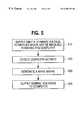
- FIG. 5is a flow chart illustrating a method of waking the computer of FIG. 2 from a power saving mode according to an embodiment of the present invention.
- the power supply 210supplies only the standby voltage when in the power saving mode.
- the I/O device 216detects computer activity from the keyboard 220 , mouse 222 , LAN controller 237 , modem controller 239 or other device.
- I/O device 216generates and outputs a wake signal in response to detecting computer activity.
- power management device 214In response to the wake signal, power management device 214 outputs power control signals to power supply 210 to supply the normal voltages to the computer.
- FIG. 6illustrates a block diagram of a portion of a computer 600 including an improved power management system according to an embodiment of the present invention.
- Computer 600includes many of the same components included in computer 200 , FIG. 2 .
- Computer 600also includes an infra-red (IR) transceiver 610 connected to an IR interface of I/O device 216 via control and data signals 605 .
- the IR transceiver 610transmits and receives IR signals.
- the IR transceiverconverts received IR signals to electrical signals for output to the I/O device 216 , and converts electrical signals to IR signals for transmission.
- the IR transceiver 610can be used to remotely control computer 600 , to download files from a laptop computer to computer 600 without using a cable, and for other applications.
- the host processor 204programs the IR interface of the I/O device 216 to detect a predetermined IR pattern.
- the power supply 210ceases supplying the normal voltages.
- the standby voltage output from power supply 210 over line 234is supplied to the I/O device 216 , the power management device 214 , and the IR transceiver 610 to allow IR transceiver 610 to wake computer 600 .
- the standby power signalallows the IR transceiver 610 to receive an IR signal and forward the IR signal to I/O device 216 for comparison. Because the I/O device 216 also receives the standby voltage via line 234 , I/O device 216 compares the received IR pattern to the predetermined IR pattern. If the received pattern matches the predetermined pattern, the I/O device 216 outputs a wake signal over line 236 to power management device 214 . As described above in connection with FIG. 2, power management device 214 then outputs the appropriate power control signals over lines 232 to power supply 210 . The normal voltages are then supplied from power supply 210 to wake the computer 600 .
- FIG. 7illustrates a block diagram of a portion of a computer 700 including an improved power management system according to an embodiment of the present invention.
- Computer 700includes many of the same components included in computer 200 , FIG. 2 .
- Computer 700also includes an interface 710 for the IEEE 1394-1995 High Speed Serial Bus Standard.
- the 1394 interface 710is connected to 1394 ports 725 A-C via lines 722 A-C, respectively.
- 1394 Ports 725 A-Care connected to 1394 devices A-C via cables 727 A-C, respectively.
- the 1394 interface 710is also connected to PCI bus 735 .
- the host processor 204can communicate with the 1394 devices via the PCI bus 735 .
- the 1394 busis a new standard for connecting a variety of audio and video products to a computer, including a VCR, a camcorder, a digital camera, a Musical Instrument Digital Interface (MIDI) device, set-top boxes, High Definition Television (HDTV) sets, local area networks (LANs), etc.
- VCRVideo Coding Control
- camcordera digital camera
- MIDIMusical Instrument Digital Interface
- HDTVHigh Definition Television
- LANslocal area networks
- the 1394 interface 710includes a PHY chip 720 and a Link chip 715 .
- the PHY chip 720implements the physical layer protocol, and can include drivers and receivers that send and receive data.
- the Link chip 715is the implementation of the link layer protocol and the transaction layer protocol.
- the Link chip 515sends and receives data by forming it into packets and adding headers. The packets are then sent to a specified 1394 device (or specified 1394 port).
- the Link chip 715wants to send a packet, the Link chip 715 asks the PHY chip 720 to obtain access to the 1394 serial bus.
- the link chip 715sends parallel data to the PHY for serialization and transmission over the cable 727 .
- power supply 210ceases supplying the normal voltages.
- the standby voltagesare supplied to the PHY chip 720 .
- the PHY chip 720operates to transfer data between any two 1394 ports. For example, a camcorder connected to 1394 port A may be outputting video to be recorded on a VCR, connected to 1394 port B. In such case, the PHY chip 720 transfers the camcorder data to the VCR. While transferring data between ports, the PHY chip 720 monitors the received data for a predetermined pattern. If the received data matches a predetermined pattern, the PHY chip outputs a wake signal over line 236 to power management device 214 . Power management device 214 then controls the power supply 210 to output the normal voltages, and thereby wake computer 700 .
- the improved power management system of the present inventionprovides a dual mode power supply 210 that supplies normal voltages, standby voltages and DRAM voltages.
- the power supply 210is controlled to cease supplying the normal voltages to conserve power.
- the standby poweris supplied to specific devices that may be involved in waking the computer. These specific wake devices can include, for example, a power management device 214 , an I/O device 216 , connectors 218 , an IR transceiver 610 , a PHY chip 720 for a 1394 interface, 1394 ports 725 , a LAN controller 237 , a modem controller 239 , other peripheral devices, and the like.
- a wake signalis generated and output to the power management device 214 .
- the power management device 214then controls the power supply to supply the normal voltages and thereby wake the computer.
Landscapes
- Engineering & Computer Science (AREA)
- Theoretical Computer Science (AREA)
- Physics & Mathematics (AREA)
- General Engineering & Computer Science (AREA)
- General Physics & Mathematics (AREA)
- Power Engineering (AREA)
- Power Sources (AREA)
Abstract
Description
Claims (17)
Priority Applications (1)
| Application Number | Priority Date | Filing Date | Title |
|---|---|---|---|
| US09/001,102US6308278B1 (en) | 1997-12-29 | 1997-12-30 | Supplying standby voltage to memory and wakeup circuitry to wake a computer from a low power mode |
Applications Claiming Priority (2)
| Application Number | Priority Date | Filing Date | Title |
|---|---|---|---|
| US08/999,492US6092207A (en) | 1997-12-29 | 1997-12-29 | Computer having a dual mode power supply for implementing a power saving mode |
| US09/001,102US6308278B1 (en) | 1997-12-29 | 1997-12-30 | Supplying standby voltage to memory and wakeup circuitry to wake a computer from a low power mode |
Related Parent Applications (1)
| Application Number | Title | Priority Date | Filing Date |
|---|---|---|---|
| US08/999,492Continuation-In-PartUS6092207A (en) | 1997-12-29 | 1997-12-29 | Computer having a dual mode power supply for implementing a power saving mode |
Publications (1)
| Publication Number | Publication Date |
|---|---|
| US6308278B1true US6308278B1 (en) | 2001-10-23 |
Family
ID=46255876
Family Applications (1)
| Application Number | Title | Priority Date | Filing Date |
|---|---|---|---|
| US09/001,102Expired - LifetimeUS6308278B1 (en) | 1997-12-29 | 1997-12-30 | Supplying standby voltage to memory and wakeup circuitry to wake a computer from a low power mode |
Country Status (1)
| Country | Link |
|---|---|
| US (1) | US6308278B1 (en) |
Cited By (51)
| Publication number | Priority date | Publication date | Assignee | Title |
|---|---|---|---|---|
| US20020023236A1 (en)* | 2000-08-18 | 2002-02-21 | Toshiro Obitsu | Information processing system and control method |
| US6438701B1 (en)* | 1999-07-21 | 2002-08-20 | Compaq Information Technologies Group, L.P. | Method and apparatus for externally generating system control interrupts as resume events from power-on suspend mode |
| US6460143B1 (en)* | 1999-05-13 | 2002-10-01 | Apple Computer, Inc. | Apparatus and method for awakening bus circuitry from a low power state |
| US20020144074A1 (en)* | 2001-03-28 | 2002-10-03 | Chung-Che Wu | Method and motherboard for automatically determining memory type |
| US20030070103A1 (en)* | 2001-09-15 | 2003-04-10 | Lg Electronics Inc. | Power supply controlling apparatus of a device connected to a serial bus |
| US6557107B1 (en)* | 1998-11-18 | 2003-04-29 | Samsung Electronics Co., Ltd. | Power-saving mode release error detection and recovery logic circuit for microcontroller devices |
| US6591368B1 (en)* | 1998-07-30 | 2003-07-08 | Samsung Electronics Co., Ltd. | Method and apparatus for controlling power of computer system using wake up LAN (local area network) signal |
| US20030135726A1 (en)* | 2001-12-26 | 2003-07-17 | International Business Machines Corporation | Computer apparatus, power supply control method and program for reducing the standby power requirement in a computer supporting a wake-up function |
| EP1338947A1 (en)* | 2002-02-22 | 2003-08-27 | Hewlett-Packard Company | A power state sub-system and a method of changing the power state of a selected computer system |
| US20030190949A1 (en)* | 2002-04-03 | 2003-10-09 | Williams Richard C. | Gaming apparatus with power saving feature |
| US6654896B1 (en)* | 2000-05-16 | 2003-11-25 | Hewlett-Packard Development Company, L.P. | Handling of multiple compliant and non-compliant wake-up sources in a computer system |
| US6708278B2 (en)* | 1999-06-28 | 2004-03-16 | Apple Computer, Inc. | Apparatus and method for awakening bus circuitry from a low power state |
| US20040053643A1 (en)* | 2002-09-13 | 2004-03-18 | Fujitsu Limited | Gateway card, gateway device, gateway control method, and computer product |
| US6711691B1 (en) | 1999-05-13 | 2004-03-23 | Apple Computer, Inc. | Power management for computer systems |
| US20040073824A1 (en)* | 2002-10-09 | 2004-04-15 | Toshiba Tec Kabushiki Kaisha | Information processing device with sleep mode function |
| US6727952B1 (en)* | 1999-02-02 | 2004-04-27 | Sanyo Electric Co., Ltd. | Electronic device having common connector |
| US6738915B1 (en)* | 2000-05-12 | 2004-05-18 | Sun Microsystems, Inc. | System for supplying multiple voltages to devices on circuit board through a sequencing in a predictable sequence |
| US6760851B2 (en)* | 2000-04-28 | 2004-07-06 | Kabushiki Kaisha Toshiba | Power savings information processing apparatus |
| US20040133818A1 (en)* | 2002-10-18 | 2004-07-08 | Nokia Corporation | Method for changing the mode of a card, a system, a card, and a device |
| US20040148533A1 (en)* | 2003-01-28 | 2004-07-29 | Ken Nicholas | Power management controller and method |
| US6772356B1 (en) | 2000-04-05 | 2004-08-03 | Advanced Micro Devices, Inc. | System for specifying core voltage for a microprocessor by selectively outputting one of a first, fixed and a second, variable voltage control settings from the microprocessor |
| US20050010828A1 (en)* | 2003-06-09 | 2005-01-13 | Lg Electronics Inc. | Device and method for managing power in computer system |
| US20050014480A1 (en)* | 2003-07-15 | 2005-01-20 | Clark Lawrence T. | Power supply delivery for leakage suppression modes |
| US20050086547A1 (en)* | 2003-10-06 | 2005-04-21 | Kobayashi Grant H. | Optimization of SMI handling and initialization |
| US6895515B1 (en)* | 1999-09-16 | 2005-05-17 | International Business Machines Corporation | Computer and power control method for executing predetermined process in said computer prior to turning off its power |
| US20050128345A1 (en)* | 2003-12-10 | 2005-06-16 | Larner Joel B. | Method for rapid power-on to first picture in a digital camera |
| US20050138441A1 (en)* | 2003-12-19 | 2005-06-23 | Huffman Amber D. | Power management without interrupt latency |
| US20060041611A1 (en)* | 2004-08-19 | 2006-02-23 | Shinichiro Fujita | Data transfer control system, electronic apparatus, and program |
| US20060101294A1 (en)* | 2004-11-10 | 2006-05-11 | Inca Solution Co., Ltd. | Apparatus for controlling standby power |
| US20060109384A1 (en)* | 2002-12-21 | 2006-05-25 | Koninkliklijke Philips Electronics N.V. | Power management in appliances |
| US20060184810A1 (en)* | 2005-02-15 | 2006-08-17 | Sharp Kabushiki Kaisha | Job processing apparatus |
| US20060236402A1 (en)* | 2005-04-15 | 2006-10-19 | Tekelec | Methods, systems, and computer program products for detecting and mitigating denial of service attacks in a telecommunications signaling network |
| US20060280005A1 (en)* | 2005-06-13 | 2006-12-14 | Hon Hai Precision Industry Co., Ltd. | Memory voltage generating circuit |
| US20070076747A1 (en)* | 2005-09-30 | 2007-04-05 | Amir Zinaty | Periodic network controller power-down |
| US20080034242A1 (en)* | 2006-08-01 | 2008-02-07 | Renesas Technology Corp. | Semiconductor integrated circuit |
| US20080065917A1 (en)* | 2006-09-13 | 2008-03-13 | Hajime Suzukawa | Information Processing Apparatus and Resume Control Method |
| US20100058081A1 (en)* | 2008-09-04 | 2010-03-04 | Mao Lihua | Mutual awakening system and method thereof between a handheld device and a wireless communication module |
| US20100262849A1 (en)* | 2009-04-10 | 2010-10-14 | Micro-Star International Co., Ltd. | Electronic device for reducing power consumption during sleep mode of computer motherboard and motherboard thereof |
| US20120096296A1 (en)* | 2008-10-14 | 2012-04-19 | Kum Cheong Adam Chan | System for reducing power consumption in an electronic chip |
| US20140289504A1 (en)* | 2013-03-20 | 2014-09-25 | Hon Hai Precision Industry Co., Ltd. | Computer with starting up keyboard |
| EP2673685A4 (en)* | 2011-02-07 | 2015-08-05 | Silicon Image Inc | MECHANISM FOR LOW POWER SLEEP MODE CONTROL CIRCUIT |
| US9264533B2 (en) | 2000-01-07 | 2016-02-16 | Tq Delta, Llc | Systems and methods for establishing a diagnostic transmission mode and communicating over the same |
| US9286251B2 (en) | 2004-10-12 | 2016-03-15 | Tq Delta, Llc | Resource sharing in a telecommunications environment |
| US9300324B2 (en) | 2004-09-25 | 2016-03-29 | Tq Delta, Llc | CRC counter normalization |
| US9300601B2 (en) | 2001-10-05 | 2016-03-29 | Tq Delta, Llc | Bonding device and method |
| US20160132101A1 (en)* | 2003-02-14 | 2016-05-12 | Intel Corporation | Non main cpu/os based operational environment |
| US9485128B2 (en) | 1999-11-09 | 2016-11-01 | Tq Delta, Llc | System and method for scrambling using a bit scrambler and a phase scrambler |
| US9485055B2 (en) | 2006-04-12 | 2016-11-01 | Tq Delta, Llc | Packet retransmission and memory sharing |
| US9521003B2 (en) | 1998-01-26 | 2016-12-13 | Tq Delta, Llc | Multicarrier transmission system with low power sleep mode and rapid-on capability |
| US9927855B2 (en) | 2014-01-27 | 2018-03-27 | Hewlett-Packard Development Company, L.P. | Power state control signal |
| US10567112B2 (en) | 2004-03-03 | 2020-02-18 | Tq Delta, Llc | Impulse noise management |
Citations (21)
| Publication number | Priority date | Publication date | Assignee | Title |
|---|---|---|---|---|
| US5167024A (en) | 1989-09-08 | 1992-11-24 | Apple Computer, Inc. | Power management for a laptop computer with slow and sleep modes |
| US5375247A (en)* | 1988-07-28 | 1994-12-20 | Robert Bosch Gmbh | Apparatus for controlled switching of a microcomputer to standby mode |
| US5396636A (en)* | 1991-10-21 | 1995-03-07 | International Business Machines Corporation | Remote power control via data link |
| US5404544A (en)* | 1992-06-05 | 1995-04-04 | Advanced Micro Devices | System for periodically transmitting signal to/from sleeping node identifying its existence to a network and awakening the sleeping node responding to received instruction |
| US5530879A (en) | 1994-09-07 | 1996-06-25 | International Business Machines Corporation | Computer system having power management processor for switching power supply from one state to another responsive to a closure of a switch, a detected ring or an expiration of a timer |
| US5548763A (en) | 1993-07-26 | 1996-08-20 | International Business Machines Corporation | Desk top computer system having multi-level power management |
| US5579524A (en)* | 1993-10-04 | 1996-11-26 | Elonex I.P. Holdings, Ltd. | Optimized power supply system for computer equipment |
| US5638541A (en) | 1995-08-25 | 1997-06-10 | Intel Corporation | System and method for managing power on desktop systems |
| US5652895A (en) | 1995-12-26 | 1997-07-29 | Intel Corporation | Computer system having a power conservation mode and utilizing a bus arbiter device which is operable to control the power conservation mode |
| US5652890A (en)* | 1991-05-17 | 1997-07-29 | Vantus Technologies, Inc. | Interrupt for a protected mode microprocessor which facilitates transparent entry to and exit from suspend mode |
| US5664203A (en)* | 1994-12-22 | 1997-09-02 | Samsung Electronics Co., Ltd. | Peripheral device input-initiated resume system for combined hibernation system and back-up power supply for computer |
| US5692197A (en)* | 1995-03-31 | 1997-11-25 | Sun Microsystems, Inc. | Method and apparatus for reducing power consumption in a computer network without sacrificing performance |
| US5708819A (en)* | 1995-10-10 | 1998-01-13 | Standard Microsystems Corporation | Process and apparatus for generating power management events in a computer system |
| US5721932A (en)* | 1992-01-08 | 1998-02-24 | Itoh; Hiromichi | Information processing apparatus with resume function and information processing system |
| US5742514A (en)* | 1992-10-20 | 1998-04-21 | Compaq Computer Corporation | Integrated remote asynchronous power switch |
| US5784628A (en)* | 1996-03-12 | 1998-07-21 | Microsoft Corporation | Method and system for controlling power consumption in a computer system |
| US5790873A (en)* | 1996-07-23 | 1998-08-04 | Standard Microsystems Corporation | Method and apparatus for power supply switching with logic integrity protection |
| US5799196A (en)* | 1996-07-02 | 1998-08-25 | Gateway 2000, Inc. | Method and apparatus of providing power management using a self-powered universal serial bus (USB) device |
| US5848281A (en)* | 1996-07-23 | 1998-12-08 | Smalley; Kenneth George | Method and apparatus for powder management in a multifunction controller with an embedded microprocessor |
| US5852737A (en)* | 1995-04-24 | 1998-12-22 | National Semiconductor Corporation | Method and apparatus for operating digital static CMOS components in a very low voltage mode during power-down |
| US6092207A (en)* | 1997-12-29 | 2000-07-18 | Intel Corporation | Computer having a dual mode power supply for implementing a power saving mode |
- 1997
- 1997-12-30USUS09/001,102patent/US6308278B1/ennot_activeExpired - Lifetime
Patent Citations (21)
| Publication number | Priority date | Publication date | Assignee | Title |
|---|---|---|---|---|
| US5375247A (en)* | 1988-07-28 | 1994-12-20 | Robert Bosch Gmbh | Apparatus for controlled switching of a microcomputer to standby mode |
| US5167024A (en) | 1989-09-08 | 1992-11-24 | Apple Computer, Inc. | Power management for a laptop computer with slow and sleep modes |
| US5652890A (en)* | 1991-05-17 | 1997-07-29 | Vantus Technologies, Inc. | Interrupt for a protected mode microprocessor which facilitates transparent entry to and exit from suspend mode |
| US5396636A (en)* | 1991-10-21 | 1995-03-07 | International Business Machines Corporation | Remote power control via data link |
| US5721932A (en)* | 1992-01-08 | 1998-02-24 | Itoh; Hiromichi | Information processing apparatus with resume function and information processing system |
| US5404544A (en)* | 1992-06-05 | 1995-04-04 | Advanced Micro Devices | System for periodically transmitting signal to/from sleeping node identifying its existence to a network and awakening the sleeping node responding to received instruction |
| US5742514A (en)* | 1992-10-20 | 1998-04-21 | Compaq Computer Corporation | Integrated remote asynchronous power switch |
| US5548763A (en) | 1993-07-26 | 1996-08-20 | International Business Machines Corporation | Desk top computer system having multi-level power management |
| US5579524A (en)* | 1993-10-04 | 1996-11-26 | Elonex I.P. Holdings, Ltd. | Optimized power supply system for computer equipment |
| US5530879A (en) | 1994-09-07 | 1996-06-25 | International Business Machines Corporation | Computer system having power management processor for switching power supply from one state to another responsive to a closure of a switch, a detected ring or an expiration of a timer |
| US5664203A (en)* | 1994-12-22 | 1997-09-02 | Samsung Electronics Co., Ltd. | Peripheral device input-initiated resume system for combined hibernation system and back-up power supply for computer |
| US5692197A (en)* | 1995-03-31 | 1997-11-25 | Sun Microsystems, Inc. | Method and apparatus for reducing power consumption in a computer network without sacrificing performance |
| US5852737A (en)* | 1995-04-24 | 1998-12-22 | National Semiconductor Corporation | Method and apparatus for operating digital static CMOS components in a very low voltage mode during power-down |
| US5638541A (en) | 1995-08-25 | 1997-06-10 | Intel Corporation | System and method for managing power on desktop systems |
| US5708819A (en)* | 1995-10-10 | 1998-01-13 | Standard Microsystems Corporation | Process and apparatus for generating power management events in a computer system |
| US5652895A (en) | 1995-12-26 | 1997-07-29 | Intel Corporation | Computer system having a power conservation mode and utilizing a bus arbiter device which is operable to control the power conservation mode |
| US5784628A (en)* | 1996-03-12 | 1998-07-21 | Microsoft Corporation | Method and system for controlling power consumption in a computer system |
| US5799196A (en)* | 1996-07-02 | 1998-08-25 | Gateway 2000, Inc. | Method and apparatus of providing power management using a self-powered universal serial bus (USB) device |
| US5790873A (en)* | 1996-07-23 | 1998-08-04 | Standard Microsystems Corporation | Method and apparatus for power supply switching with logic integrity protection |
| US5848281A (en)* | 1996-07-23 | 1998-12-08 | Smalley; Kenneth George | Method and apparatus for powder management in a multifunction controller with an embedded microprocessor |
| US6092207A (en)* | 1997-12-29 | 2000-07-18 | Intel Corporation | Computer having a dual mode power supply for implementing a power saving mode |
Non-Patent Citations (6)
| Title |
|---|
| 82371AB PCI-To-ISA/IDE Xcelerator (PIIx4), Apr. 1, 1997, Intel Corporation, pp. 1-225. |
| Advanced Configuration and Power Interface Specification (ACPI), Rev. 1.0, Dec. 22, 1996, pp. 1-1 to 16-260. |
| Bosker, J., & Kienzle, M., Oct. 10, 1997, Fast Infrared Technology for Cordless Connectivity, IBM MicroNews, pp. 1-6. |
| Mullgrave, Jr., A. Oct. 19, 1997, IBM Chips at 200Mbps Drive 1394 High-Speed Serial Bus, IBM MicroNews, pp. 1-6. |
| SMC's FDC37C67x, 100 Pin Enhanced Super I/O Controller with Fast IR, Jul. 10, 1997, Standard Microsystems Corporation, pp. 1-2. |
| SMC's PC Input/Output Products, Jul. 10, 1997, Standard Microsystems Corporation, pp. 1-4. |
Cited By (107)
| Publication number | Priority date | Publication date | Assignee | Title |
|---|---|---|---|---|
| US9521003B2 (en) | 1998-01-26 | 2016-12-13 | Tq Delta, Llc | Multicarrier transmission system with low power sleep mode and rapid-on capability |
| US6591368B1 (en)* | 1998-07-30 | 2003-07-08 | Samsung Electronics Co., Ltd. | Method and apparatus for controlling power of computer system using wake up LAN (local area network) signal |
| US6557107B1 (en)* | 1998-11-18 | 2003-04-29 | Samsung Electronics Co., Ltd. | Power-saving mode release error detection and recovery logic circuit for microcontroller devices |
| US6727952B1 (en)* | 1999-02-02 | 2004-04-27 | Sanyo Electric Co., Ltd. | Electronic device having common connector |
| US6460143B1 (en)* | 1999-05-13 | 2002-10-01 | Apple Computer, Inc. | Apparatus and method for awakening bus circuitry from a low power state |
| US6711691B1 (en) | 1999-05-13 | 2004-03-23 | Apple Computer, Inc. | Power management for computer systems |
| US6708278B2 (en)* | 1999-06-28 | 2004-03-16 | Apple Computer, Inc. | Apparatus and method for awakening bus circuitry from a low power state |
| US6438701B1 (en)* | 1999-07-21 | 2002-08-20 | Compaq Information Technologies Group, L.P. | Method and apparatus for externally generating system control interrupts as resume events from power-on suspend mode |
| US6895515B1 (en)* | 1999-09-16 | 2005-05-17 | International Business Machines Corporation | Computer and power control method for executing predetermined process in said computer prior to turning off its power |
| US9485128B2 (en) | 1999-11-09 | 2016-11-01 | Tq Delta, Llc | System and method for scrambling using a bit scrambler and a phase scrambler |
| US9755876B2 (en) | 1999-11-09 | 2017-09-05 | Tq Delta, Llc | System and method for scrambling the phase of the carriers in a multicarrier communications system |
| US10187240B2 (en) | 1999-11-09 | 2019-01-22 | Tq Delta, Llc | System and method for scrambling the phase of the carriers in a multicarrier communications system |
| US9838531B2 (en) | 2000-01-07 | 2017-12-05 | Tq Delta, Llc | Systems and methods for establishing a diagnostic transmission mode and communicating over the same |
| US9973624B2 (en) | 2000-01-07 | 2018-05-15 | Tq Delta, Llc | Systems and methods for establishing a diagnostic transmission mode and communicating over the same |
| US9264533B2 (en) | 2000-01-07 | 2016-02-16 | Tq Delta, Llc | Systems and methods for establishing a diagnostic transmission mode and communicating over the same |
| US10264119B2 (en) | 2000-01-07 | 2019-04-16 | Tq Delta, Llc | Systems and methods for establishing a diagnostic transmission mode and communicating over the same |
| US9479637B2 (en) | 2000-01-07 | 2016-10-25 | Tq Delta, Llc | Systems and methods for establishing a diagnostic transmission mode and communicating over the same |
| US10623559B2 (en) | 2000-01-07 | 2020-04-14 | Tq Delta, Llc | Systems and methods for establishing a diagnostic transmission mode and communicating over the same |
| US9319512B2 (en) | 2000-01-07 | 2016-04-19 | Tq Delta, Llc | Systems and methods for establishing a diagnostic transmission mode and communicating over the same |
| US6772356B1 (en) | 2000-04-05 | 2004-08-03 | Advanced Micro Devices, Inc. | System for specifying core voltage for a microprocessor by selectively outputting one of a first, fixed and a second, variable voltage control settings from the microprocessor |
| US6760851B2 (en)* | 2000-04-28 | 2004-07-06 | Kabushiki Kaisha Toshiba | Power savings information processing apparatus |
| US6738915B1 (en)* | 2000-05-12 | 2004-05-18 | Sun Microsystems, Inc. | System for supplying multiple voltages to devices on circuit board through a sequencing in a predictable sequence |
| US20040128571A1 (en)* | 2000-05-16 | 2004-07-01 | Saunders Scott P. | Handling of multiple compliant and non-compliant wake-up sources in a computer system |
| US6654896B1 (en)* | 2000-05-16 | 2003-11-25 | Hewlett-Packard Development Company, L.P. | Handling of multiple compliant and non-compliant wake-up sources in a computer system |
| US20020023236A1 (en)* | 2000-08-18 | 2002-02-21 | Toshiro Obitsu | Information processing system and control method |
| US6851066B2 (en)* | 2000-08-18 | 2005-02-01 | Fujitsu Limited | Information processing system and control method |
| US20020144074A1 (en)* | 2001-03-28 | 2002-10-03 | Chung-Che Wu | Method and motherboard for automatically determining memory type |
| US6904506B2 (en)* | 2001-03-28 | 2005-06-07 | Via Technologies, Inc. | Method and motherboard for automatically determining memory type |
| US20030070103A1 (en)* | 2001-09-15 | 2003-04-10 | Lg Electronics Inc. | Power supply controlling apparatus of a device connected to a serial bus |
| US7320077B2 (en)* | 2001-09-15 | 2008-01-15 | Lg Electronics Inc. | Power supply controlling apparatus of a device connected to a serial bus |
| US9300601B2 (en) | 2001-10-05 | 2016-03-29 | Tq Delta, Llc | Bonding device and method |
| US9894014B2 (en) | 2001-10-05 | 2018-02-13 | Tq Delta, Llc | Bonding device and method |
| US10341261B2 (en) | 2001-10-05 | 2019-07-02 | Tq Delta, Llc | Bonding device and method |
| US20030135726A1 (en)* | 2001-12-26 | 2003-07-17 | International Business Machines Corporation | Computer apparatus, power supply control method and program for reducing the standby power requirement in a computer supporting a wake-up function |
| US7117377B2 (en)* | 2001-12-26 | 2006-10-03 | Lenovo (Singapore) Pte Ltd. | Computer apparatus, power supply control method and program for reducing the standby power requirement in a computer supporting a wake-up function |
| EP1338947A1 (en)* | 2002-02-22 | 2003-08-27 | Hewlett-Packard Company | A power state sub-system and a method of changing the power state of a selected computer system |
| US20030233591A1 (en)* | 2002-02-22 | 2003-12-18 | Thierry Chiteboun | Power state sub-system and a method of changing the power state of a selected computer system |
| US7670224B2 (en)* | 2002-04-03 | 2010-03-02 | Igt | Gaming apparatus with power saving feature |
| US20030190949A1 (en)* | 2002-04-03 | 2003-10-09 | Williams Richard C. | Gaming apparatus with power saving feature |
| US20040053643A1 (en)* | 2002-09-13 | 2004-03-18 | Fujitsu Limited | Gateway card, gateway device, gateway control method, and computer product |
| US7966503B2 (en)* | 2002-09-13 | 2011-06-21 | Fujitsu Limited | Gateway card, gateway device, gateway control method, and computer product |
| US20040073824A1 (en)* | 2002-10-09 | 2004-04-15 | Toshiba Tec Kabushiki Kaisha | Information processing device with sleep mode function |
| US20040133818A1 (en)* | 2002-10-18 | 2004-07-08 | Nokia Corporation | Method for changing the mode of a card, a system, a card, and a device |
| US20060109384A1 (en)* | 2002-12-21 | 2006-05-25 | Koninkliklijke Philips Electronics N.V. | Power management in appliances |
| US20040148533A1 (en)* | 2003-01-28 | 2004-07-29 | Ken Nicholas | Power management controller and method |
| US7100062B2 (en) | 2003-01-28 | 2006-08-29 | Hewlett-Packard Development Company, L.P. | Power management controller and method |
| US10078363B2 (en)* | 2003-02-14 | 2018-09-18 | Intel Corporation | Non main CPU/OS based operational environment |
| US20160132101A1 (en)* | 2003-02-14 | 2016-05-12 | Intel Corporation | Non main cpu/os based operational environment |
| US7243247B2 (en)* | 2003-06-09 | 2007-07-10 | Lg Electronics Inc. | Method for rechecking whether a CPU enters a powr saving stat after a delay ad forcing the CPU to enter power saving state depending on the result |
| US20050010828A1 (en)* | 2003-06-09 | 2005-01-13 | Lg Electronics Inc. | Device and method for managing power in computer system |
| US7428649B2 (en)* | 2003-07-15 | 2008-09-23 | Marvell International Ltd. | Power supply delivery for leakage suppression modes |
| US8307232B1 (en) | 2003-07-15 | 2012-11-06 | Marvell International Ltd. | Power supply delivery for leakage suppression modes |
| US8589711B1 (en) | 2003-07-15 | 2013-11-19 | Marvell International Ltd. | Power supply delivery for leakage suppression modes |
| US7805625B1 (en) | 2003-07-15 | 2010-09-28 | Marvell International Ltd. | Power supply delivery for leakage suppression modes |
| US20050014480A1 (en)* | 2003-07-15 | 2005-01-20 | Clark Lawrence T. | Power supply delivery for leakage suppression modes |
| US7493435B2 (en)* | 2003-10-06 | 2009-02-17 | Intel Corporation | Optimization of SMI handling and initialization |
| US20050086547A1 (en)* | 2003-10-06 | 2005-04-21 | Kobayashi Grant H. | Optimization of SMI handling and initialization |
| US7342611B2 (en)* | 2003-12-10 | 2008-03-11 | Hewlett-Packard Development Company, L.P. | Method for rapid power-on to first picture in a digital camera |
| US20050128345A1 (en)* | 2003-12-10 | 2005-06-16 | Larner Joel B. | Method for rapid power-on to first picture in a digital camera |
| US20050138441A1 (en)* | 2003-12-19 | 2005-06-23 | Huffman Amber D. | Power management without interrupt latency |
| US10567112B2 (en) | 2004-03-03 | 2020-02-18 | Tq Delta, Llc | Impulse noise management |
| US10805040B2 (en) | 2004-03-03 | 2020-10-13 | Tq Delta, Llc | Impulse noise management |
| US11005591B2 (en) | 2004-03-03 | 2021-05-11 | Tq Delta, Llc | Impulse noise management |
| US20060041611A1 (en)* | 2004-08-19 | 2006-02-23 | Shinichiro Fujita | Data transfer control system, electronic apparatus, and program |
| US10049003B2 (en) | 2004-09-25 | 2018-08-14 | Tq Delta, Llc | CRC counter normalization |
| US10346243B2 (en) | 2004-09-25 | 2019-07-09 | Tq Delta, Llc | CRC counter normalization |
| US9300324B2 (en) | 2004-09-25 | 2016-03-29 | Tq Delta, Llc | CRC counter normalization |
| US9547608B2 (en) | 2004-10-12 | 2017-01-17 | Tq Delta, Llc | Resource sharing in a telecommunications environment |
| US10409510B2 (en) | 2004-10-12 | 2019-09-10 | Tq Delta, Llc | Resource sharing in a telecommunications environment |
| US11543979B2 (en) | 2004-10-12 | 2023-01-03 | Tq Delta, Llc | Resource sharing in a telecommunications environment |
| US11010073B2 (en) | 2004-10-12 | 2021-05-18 | Tq Delta, Llc | Resource sharing in a telecommunications environment |
| US9898220B2 (en) | 2004-10-12 | 2018-02-20 | Tq Delta, Llc | Resource sharing in a telecommunications environment |
| US9286251B2 (en) | 2004-10-12 | 2016-03-15 | Tq Delta, Llc | Resource sharing in a telecommunications environment |
| US10579291B2 (en) | 2004-10-12 | 2020-03-03 | Tq Delta, Llc | Resource sharing in a telecommunications environment |
| US20060101294A1 (en)* | 2004-11-10 | 2006-05-11 | Inca Solution Co., Ltd. | Apparatus for controlling standby power |
| US7380142B2 (en)* | 2004-11-10 | 2008-05-27 | Inca Solution Co., Ltd. | Apparatus for controlling standby power |
| US20060184810A1 (en)* | 2005-02-15 | 2006-08-17 | Sharp Kabushiki Kaisha | Job processing apparatus |
| US7523335B2 (en)* | 2005-02-15 | 2009-04-21 | Sharp Kabushiki Kaisha | Job processing apparatus with power sequence responsive to detecting external job data signal |
| US20060236402A1 (en)* | 2005-04-15 | 2006-10-19 | Tekelec | Methods, systems, and computer program products for detecting and mitigating denial of service attacks in a telecommunications signaling network |
| US20060280005A1 (en)* | 2005-06-13 | 2006-12-14 | Hon Hai Precision Industry Co., Ltd. | Memory voltage generating circuit |
| US7408816B2 (en)* | 2005-06-13 | 2008-08-05 | Hong Fu Jin Precision Industry (Shenzhen) Co., Ltd. | Memory voltage generating circuit |
| US20070076747A1 (en)* | 2005-09-30 | 2007-04-05 | Amir Zinaty | Periodic network controller power-down |
| US10498495B2 (en) | 2006-04-12 | 2019-12-03 | Tq Delta, Llc | Packet retransmission |
| US9749235B2 (en) | 2006-04-12 | 2017-08-29 | Tq Delta, Llc | Packet retransmission |
| US9485055B2 (en) | 2006-04-12 | 2016-11-01 | Tq Delta, Llc | Packet retransmission and memory sharing |
| US10044473B2 (en) | 2006-04-12 | 2018-08-07 | Tq Delta, Llc | Packet retransmission and memory sharing |
| US10833809B2 (en) | 2006-04-12 | 2020-11-10 | Tq Delta, Llc | Techniques for packet and message communication in a multicarrier transceiver environment |
| US12101188B2 (en) | 2006-04-12 | 2024-09-24 | Tq Delta, Llc | Multicarrier transceiver that includes a retransmission function and an interleaving function |
| US11362765B2 (en) | 2006-04-12 | 2022-06-14 | Tq Delta, Llc | Packet retransmission using one or more delay requirements |
| US10484140B2 (en) | 2006-04-12 | 2019-11-19 | Tq Delta, Llc | Packet retransmission and memory sharing |
| US11290216B2 (en) | 2006-04-12 | 2022-03-29 | Tq Delta, Llc | Packet retransmission and memory sharing |
| US7765415B2 (en)* | 2006-08-01 | 2010-07-27 | Renesas Technology Corp. | Semiconductor integrated circuit |
| US20080034242A1 (en)* | 2006-08-01 | 2008-02-07 | Renesas Technology Corp. | Semiconductor integrated circuit |
| US20100275048A1 (en)* | 2006-08-01 | 2010-10-28 | Renesas Technology Corp. | Semiconductor integrated circuit |
| US8214670B2 (en) | 2006-08-01 | 2012-07-03 | Renesas Electronics Corporation | Semiconductor integrated circuit device having internal circuit with plural power supply regions |
| US20080065917A1 (en)* | 2006-09-13 | 2008-03-13 | Hajime Suzukawa | Information Processing Apparatus and Resume Control Method |
| US8412146B2 (en)* | 2008-09-04 | 2013-04-02 | Inventec Appliances Corp. | Mutual awakening system and method thereof between a handheld device and a wireless communication module |
| US20100058081A1 (en)* | 2008-09-04 | 2010-03-04 | Mao Lihua | Mutual awakening system and method thereof between a handheld device and a wireless communication module |
| US20120096296A1 (en)* | 2008-10-14 | 2012-04-19 | Kum Cheong Adam Chan | System for reducing power consumption in an electronic chip |
| US8656200B2 (en)* | 2008-10-14 | 2014-02-18 | Hewlett-Packard Development Company, L.P. | System for reducing power consumption in an electronic chip |
| TWI464571B (en)* | 2009-04-10 | 2014-12-11 | Micro Star Int Co Ltd | A power saving electronic device for a computer motherboard in a standby dormant state and a computer motherboard |
| US8132032B2 (en)* | 2009-04-10 | 2012-03-06 | MSI Computer (Shenzhen) Co. Ltd. | Electronic device for reducing power consumption during sleep mode of computer motherboard and motherboard thereof |
| US20100262849A1 (en)* | 2009-04-10 | 2010-10-14 | Micro-Star International Co., Ltd. | Electronic device for reducing power consumption during sleep mode of computer motherboard and motherboard thereof |
| KR101912599B1 (en) | 2011-02-07 | 2018-10-29 | 래티스세미컨덕터코퍼레이션 | Mechanism for low power standby mode control circuit |
| EP2673685A4 (en)* | 2011-02-07 | 2015-08-05 | Silicon Image Inc | MECHANISM FOR LOW POWER SLEEP MODE CONTROL CIRCUIT |
| US20140289504A1 (en)* | 2013-03-20 | 2014-09-25 | Hon Hai Precision Industry Co., Ltd. | Computer with starting up keyboard |
| US9927855B2 (en) | 2014-01-27 | 2018-03-27 | Hewlett-Packard Development Company, L.P. | Power state control signal |
Similar Documents
| Publication | Publication Date | Title |
|---|---|---|
| US6308278B1 (en) | Supplying standby voltage to memory and wakeup circuitry to wake a computer from a low power mode | |
| US6092207A (en) | Computer having a dual mode power supply for implementing a power saving mode | |
| US5560022A (en) | Power management coordinator system and interface | |
| US5167024A (en) | Power management for a laptop computer with slow and sleep modes | |
| US6760850B1 (en) | Method and apparatus executing power on self test code to enable a wakeup device for a computer system responsive to detecting an AC power source | |
| US5590061A (en) | Method and apparatus for thermal management in a computer system | |
| US6121962A (en) | Computer system and method for controlling screen display of a monitor in a power management mode | |
| US6243831B1 (en) | Computer system with power loss protection mechanism | |
| US6920573B2 (en) | Energy-conserving apparatus and operating system having multiple operating functions stored in keep-alive memory | |
| US7437575B2 (en) | Low power mode for device power management | |
| US7219240B2 (en) | Monitor and method for controlling power-on and power-off of host computer | |
| US6421782B1 (en) | Expansion unit for differentiating wake-up packets received in an information processing system | |
| EP1508081B1 (en) | Method and apparatus for providing a decoupled power management state | |
| US20010014950A1 (en) | Computer and power saving control method thereof | |
| US7020786B2 (en) | System and method for selecting a voltage output reference | |
| EP0752637B1 (en) | Method and apparatus for powering-on a computer-based system via a network interface | |
| US20110231682A1 (en) | Power management method and related power management system | |
| CA2024552A1 (en) | Power management for a laptop computer | |
| WO2002086678A2 (en) | Power management system and method | |
| JPH10512382A (en) | Low power consumption monitor standby system for computer peripheral devices | |
| US7051144B2 (en) | Portable computer system and control method for reducing power consumption therein | |
| JPH07230347A (en) | Power-down device for scsi-disk-drive | |
| US5978924A (en) | Computer system with an advanced power saving function and an operating method therefor | |
| US20030131271A1 (en) | Pipeline module circuit structure with reduced power consumption and method for operating the same | |
| US7096299B2 (en) | Method and apparatus for transferring system context information between mobile computer and base station |
Legal Events
| Date | Code | Title | Description |
|---|---|---|---|
| AS | Assignment | Owner name:INTEL CORPORATION, CALIFORNIA Free format text:ASSIGNMENT OF ASSIGNORS INTEREST;ASSIGNORS:KHOULI, SAMI;MUGHIR, TAHA;NELSON, ALBERT RUDY;REEL/FRAME:009236/0465;SIGNING DATES FROM 19980501 TO 19980524 | |
| AS | Assignment | Owner name:INTEL CORPORATION, CALIFORNIA Free format text:ASSIGNMENT OF ASSIGNORS INTEREST;ASSIGNORS:KHOULI, SAMI;MUGHIR, TAHA;NELSON, ALBERT RUDY;REEL/FRAME:009247/0026;SIGNING DATES FROM 19980501 TO 19980524 | |
| STCF | Information on status: patent grant | Free format text:PATENTED CASE | |
| FPAY | Fee payment | Year of fee payment:4 | |
| FPAY | Fee payment | Year of fee payment:8 | |
| FPAY | Fee payment | Year of fee payment:12 | |
| AS | Assignment | Owner name:MICRON TECHNOLOGY, INC., IDAHO Free format text:ASSIGNMENT OF ASSIGNORS INTEREST;ASSIGNOR:INTEL CORPORATION;REEL/FRAME:030747/0001 Effective date:20111122 | |
| AS | Assignment | Owner name:U.S. BANK NATIONAL ASSOCIATION, AS COLLATERAL AGENT, CALIFORNIA Free format text:SECURITY INTEREST;ASSIGNOR:MICRON TECHNOLOGY, INC.;REEL/FRAME:038669/0001 Effective date:20160426 Owner name:U.S. BANK NATIONAL ASSOCIATION, AS COLLATERAL AGEN Free format text:SECURITY INTEREST;ASSIGNOR:MICRON TECHNOLOGY, INC.;REEL/FRAME:038669/0001 Effective date:20160426 | |
| AS | Assignment | Owner name:MORGAN STANLEY SENIOR FUNDING, INC., AS COLLATERAL AGENT, MARYLAND Free format text:PATENT SECURITY AGREEMENT;ASSIGNOR:MICRON TECHNOLOGY, INC.;REEL/FRAME:038954/0001 Effective date:20160426 Owner name:MORGAN STANLEY SENIOR FUNDING, INC., AS COLLATERAL Free format text:PATENT SECURITY AGREEMENT;ASSIGNOR:MICRON TECHNOLOGY, INC.;REEL/FRAME:038954/0001 Effective date:20160426 | |
| AS | Assignment | Owner name:U.S. BANK NATIONAL ASSOCIATION, AS COLLATERAL AGENT, CALIFORNIA Free format text:CORRECTIVE ASSIGNMENT TO CORRECT THE REPLACE ERRONEOUSLY FILED PATENT #7358718 WITH THE CORRECT PATENT #7358178 PREVIOUSLY RECORDED ON REEL 038669 FRAME 0001. ASSIGNOR(S) HEREBY CONFIRMS THE SECURITY INTEREST;ASSIGNOR:MICRON TECHNOLOGY, INC.;REEL/FRAME:043079/0001 Effective date:20160426 Owner name:U.S. BANK NATIONAL ASSOCIATION, AS COLLATERAL AGEN Free format text:CORRECTIVE ASSIGNMENT TO CORRECT THE REPLACE ERRONEOUSLY FILED PATENT #7358718 WITH THE CORRECT PATENT #7358178 PREVIOUSLY RECORDED ON REEL 038669 FRAME 0001. ASSIGNOR(S) HEREBY CONFIRMS THE SECURITY INTEREST;ASSIGNOR:MICRON TECHNOLOGY, INC.;REEL/FRAME:043079/0001 Effective date:20160426 | |
| AS | Assignment | Owner name:MICRON TECHNOLOGY, INC., IDAHO Free format text:RELEASE BY SECURED PARTY;ASSIGNOR:U.S. BANK NATIONAL ASSOCIATION, AS COLLATERAL AGENT;REEL/FRAME:047243/0001 Effective date:20180629 | |
| AS | Assignment | Owner name:MICRON TECHNOLOGY, INC., IDAHO Free format text:RELEASE BY SECURED PARTY;ASSIGNOR:MORGAN STANLEY SENIOR FUNDING, INC., AS COLLATERAL AGENT;REEL/FRAME:050937/0001 Effective date:20190731 |