US6308138B1 - Diagnostic rule base tool condition monitoring system - Google Patents
Diagnostic rule base tool condition monitoring systemDownload PDFInfo
- Publication number
- US6308138B1 US6308138B1US08/901,609US90160997AUS6308138B1US 6308138 B1US6308138 B1US 6308138B1US 90160997 AUS90160997 AUS 90160997AUS 6308138 B1US6308138 B1US 6308138B1
- Authority
- US
- United States
- Prior art keywords
- power consumption
- tool
- electric
- condition
- rule base
- Prior art date
- Legal status (The legal status is an assumption and is not a legal conclusion. Google has not performed a legal analysis and makes no representation as to the accuracy of the status listed.)
- Expired - Fee Related
Links
- 238000012544monitoring processMethods0.000titleclaimsabstractdescription56
- 238000000034methodMethods0.000claimsdescription24
- 125000004122cyclic groupChemical group0.000claims3
- 238000003745diagnosisMethods0.000abstractdescription22
- 238000003754machiningMethods0.000description7
- 230000006870functionEffects0.000description6
- 238000005520cutting processMethods0.000description3
- 238000004519manufacturing processMethods0.000description2
- 230000003287optical effectEffects0.000description2
- 230000003252repetitive effectEffects0.000description2
- 239000002826coolantSubstances0.000description1
- 230000007423decreaseEffects0.000description1
- 230000007547defectEffects0.000description1
- 238000001514detection methodMethods0.000description1
- 230000007613environmental effectEffects0.000description1
Images


Classifications
- G—PHYSICS
- G05—CONTROLLING; REGULATING
- G05B—CONTROL OR REGULATING SYSTEMS IN GENERAL; FUNCTIONAL ELEMENTS OF SUCH SYSTEMS; MONITORING OR TESTING ARRANGEMENTS FOR SUCH SYSTEMS OR ELEMENTS
- G05B19/00—Programme-control systems
- G05B19/02—Programme-control systems electric
- G05B19/18—Numerical control [NC], i.e. automatically operating machines, in particular machine tools, e.g. in a manufacturing environment, so as to execute positioning, movement or co-ordinated operations by means of programme data in numerical form
- G05B19/406—Numerical control [NC], i.e. automatically operating machines, in particular machine tools, e.g. in a manufacturing environment, so as to execute positioning, movement or co-ordinated operations by means of programme data in numerical form characterised by monitoring or safety
- G05B19/4065—Monitoring tool breakage, life or condition
- G—PHYSICS
- G05—CONTROLLING; REGULATING
- G05B—CONTROL OR REGULATING SYSTEMS IN GENERAL; FUNCTIONAL ELEMENTS OF SUCH SYSTEMS; MONITORING OR TESTING ARRANGEMENTS FOR SUCH SYSTEMS OR ELEMENTS
- G05B2219/00—Program-control systems
- G05B2219/30—Nc systems
- G05B2219/37—Measurements
- G05B2219/37252—Life of tool, service life, decay, wear estimation
Definitions
- the present inventionrelates to a tool monitoring system for monitoring the condition of an electric motor driven tool performing a cyclical operation.
- Tool condition monitoringis one of the major concerns in modem machining operations, especially in machining operations for mass production. Failure to detect tool failure and wear leads to poor product quality and can even damage machine tools. On the other hand, a false detection of tool failure or wear may cause an unnecessary interruption of an entire production. Both can result in significant monetary loss.
- Known tool monitoring systemsinclude systems for “on-line tool condition monitoring.” In on-line tool condition monitoring, the tool is monitored for defects after each cut or cycle. These tool monitoring systems typically use optical sensors or laser optical sensors which measure the geometry of the tool after each cut. However, on-line tool condition monitoring can only detect catastrophic failure of a tool after a cut and cannot monitor the gradual wear of a tool or predict the tool's failure. Further, these systems are vulnerable to chips, coolant, and environmental noises.
- Some monitoring systemsmonitor power consumption (or motor current) of the tool. As the tool wears (or if it fails) its power consumption changes. However, the power signals are complicated and the power signals to provide a reliable, accurate indication of it has proven difficult to use. The power signal does contain some “noise” due to factors other than tool condition. Typically, these systems sets a range of signal that a monitored signal should fall within. When the monitored signal is outside this range, a worn tool or failure is indicated.
- the inventors of the present inventionpreviously developed a tool monitoring system which operates generally in two modes: learning mode and monitoring mode.
- learning modethe tool monitoring system gathers statistical data on the power consumption of tools of the selected tool type during learning cycles.
- a power thresholdis generated based upon the statistical data.
- the tool monitoring systemthen counts the number of crossings by each of the learning cycles of the power threshold and generates statistical data regarding the number of crossings.
- the mathematical operation of wavelet packet transformis used to calculate the power threshold.
- Feature wavelet packets of the power consumption signal of the toolare calculated.
- the power consumption signalis then reconstructed from the feature wavelet packets and used to determine the power threshold.
- monitor modethe tool monitoring system counts the number of crossings of the power threshold by the power consumption signal of a tool in operation.
- the tool monitoring systemidentifies a worn tool when the number of crossings increases to a certain number relative to the crossings by the learning cycles.
- the present inventionprovides a real time tool monitoring system which continuously monitors a plurality of characteristics of the power consumption of the tool during operation in order to diagnose the condition of the tool and the likely cause of any problem.
- the tool monitoring system of the present inventionmonitors a plurality of characteristics of the power consumption of the tool during performance of the cyclical task.
- the systemdiagnoses the condition of the tool based upon the plurality of characteristics of the power consumption, including the existence or absence of each of the plurality of characteristics.
- the systemis first operated in a “learning mode,” in which one or more tools of a known condition are monitored for a plurality of cycles.
- a plurality of characteristics of the power consumption of the known toolsevaluated statistically in order to generate a plurality of threshold values.
- a power threshold having an upper limit and a lower limitis generated based upon the average power consumption.
- the power threshold and average power consumptionis a function of time over the cyclical task. During each cycle of the tool, the power consumption will cross the power threshold a plurality of times.
- Statistical information regarding the number of crossings by the power consumption of the upper and lower limits by the known toolsis gathered to establish a threshold number of crossings of the upper limit and a threshold number of crossings of the lower limit.
- extreme high and low values, i.e. “spikes,” in the power consumptionare also monitored in the known tools and evaluated statistically to generate maximum and minimum permissible values. Again, this threshold is a function of time over the cyclical task.
- the amount of time that the power consumption stays outside the power thresholdi.e. above the upper limit or below the lower limit, is also monitored statistically to generate a threshold time value.
- the values gathered in the learning modeare then utilized to generate a diagnostic rule base which includes every possible combination of the plurality of characteristics monitored, i.e. number of crossings, maximum & minimum instantaneous values, and time outside threshold. Further, for each characteristic, there are four possibilities. First, the characteristic may be absent, i.e. the number of crossings has not been exceeded, the maximum and minimum permissible values have not been crossed and the time outside the threshold has not been exceeded. When the characteristic exists there are three more possibilities: the characteristic is occurring below the lower limit of the power threshold, above the upper limit of the power threshold or both above and below the power threshold. Thus, for the three characteristics monitored in the preferred embodiment, there are sixty four possible combinations which are associated with different tool conditions in the rule base.
- FIG. 1illustrates a tool monitoring system according to the present invention, monitoring the power consumption of a machine tool machining a series of workpieces.
- FIG. 2illustrates the power signal from one cycle of the machine tool as received by the tool monitoring system of FIG. 1 .
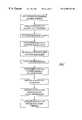
- FIG. 3is a flow chart of the tool monitoring system of FIG. 1 in its learning mode.
- FIG. 4is a reconstructed power consumption signal of FIG. 2, reconstructed from the feature wavelet packets selected from FIG. 4 .
- FIG. 5is a power threshold based upon several reconstructed power consumption signals of the learning cycles.
- FIG. 6Ais a flow chart of the tool monitoring system of FIG. 1 in monitor mode.
- FIG. 6Bis a flow chart of a control rule base for the tool monitoring system of FIG. 1 in monitor mode.
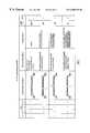
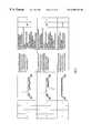
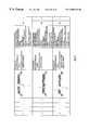
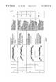
- FIG. 7is a chart showing the diagnosis rule base for rules 1 - 4 .
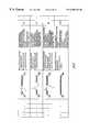
- FIG. 8is a chart of the diagnosis rule base of FIG. 7 for rules 5 - 8 .
- FIG. 9is a chart of the diagnosis rule base of FIG. 7 for rules 9 - 13 .
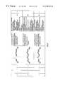
- FIG. 10is a chart of the diagnosis rule base of FIG. 7 for rules 14 - 17 .
- FIG. 11is a chart of the diagnosis rule base of FIG. 7 for rules 18 - 21 .
- FIG. 12is a chart of the diagnosis rule base of FIG. 7 for rules 22 - 24 .
- FIG. 13is a chart of the diagnosis rule base of FIG. 7 for rules 25 - 27 .
- FIG. 14is a chart of the diagnosis rule base of FIG. 7 for rules 28 - 30 .
- FIG. 15is a chart of the diagnosis rule base of FIG. 7 for rules 31 - 33 .
- FIG. 16is a chart of the diagnosis rule base of FIG. 7 for rules 34 - 37 .
- FIG. 17is a chart of the diagnosis rule base of FIG. 7 for rules 38 - 41 .
- FIG. 18is a chart of the diagnosis rule base of FIG. 7 for rules 42 - 45 .
- FIG. 19is a chart of the diagnosis rule base of FIG. 7 for rules 46 - 49 .
- FIG. 20is a chart of the diagnosis rule base of FIG. 7 for rules 50 - 53 .
- FIG. 21is a chart of the diagnosis rule base of FIG. 7 for rules 54 - 56 .
- FIG. 22is a chart of the diagnosis rule base of FIG. 7 for rules 57 - 60 .
- FIG. 23is a chart of the diagnosis rule base of FIG. 7 for rules 61 - 64 .
- FIG. 1shows a tool monitoring system 10 according to the present invention including a current transducer 12 connected to an analog-to-digital converter 14 and a CPU 16 .
- the CPU 16is also connected to a plurality of condition indicator lights 17 a-c , which are preferably green, yellow and red, respectively.
- the tool monitoring system 10is shown monitoring a machine tool 18 having an electric motor 20 driving a tool 22 .
- the machine tool 18is shown machining a series of workpieces 24 being moved along a conveyor system 26 .
- the tool monitoring system 10 of the present inventioncan be used with any selected tool type using an electric motor and performing a repetitive, cyclical task.
- the motor 20 and tool 22are repeatedly loaded to cut each workpiece 24 , and then the conveyor system 26 positions another workpiece 24 to the machine tool 18 .
- the current transducer 12continuously indicates the power consumption of the motor 20 by sending a power consumption signal to the analog-to-digital converter 14 , which converts the power consumption signal into a format readable by the CPU 16 .
- the analog-to-digital converter 14sends a digital signal representing the amplitude of the power consumption signal at a series of current time segments.
- the digitized power consumption signalis stored in the CPU 16 and associated with its particular time segment, relative to the machine tool cycle.
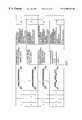
- FIG. 2shows one cycle of the power consumption signal 28 of the machine tool 18 of FIG. 1, as received by the CPU 16 .
- the machining operationis in the form of a cycle starting from tool engagement and ending with tool withdrawal.
- the tool 22is not engaging the workpiece 24 and the power consumption signal 28 is at idling power 30 .
- the power consumption signal 28rises.
- the power consumption signal 28reaches full engagement consumption 34 .
- the power consumption signal 28reaches a level and remains relatively unchanged, though there are fluctuations caused by various noise, such as cutting a hard spot in the workpiece 24 .
- the tool monitoring system 10generally operates in two modes: a learning mode and a monitoring mode.
- learning modethe tool monitoring system 10 preferably receives data from several sample cycles of machine tools 18 of the selected tool type. Information related to the power consumption during each cycle run by each machine tool 18 is stored to develop expected signal ranges, or thresholds, and other statistical values.
- monitoring modethe tool monitoring system 10 compares the power consumption signal of a machine tool 18 with data gathered in the learning mode and diagnoses the condition of the machine tool 18 for each cycle. The determination is made by comparing the signal to the expected learning cycle, signal ranges, or thresholds and other statistical data gathered from tools of a known condition. Since the thresholds are developed by samples, they are more accurate than prior art “selected” thresholds.
- FIG. 3shows a flow chart for the learning mode 40 of the tool monitoring system 10 of FIG. 1 .
- learning mode 40numerous learning cycles of a plurality of tools 22 of the selected tool type are run in 42 .
- the tool 22is selected to be a new tool or in normal condition.
- the power consumption signals 28 of the learning cycleare digitized by the analog-to-digital converter 14 and stored in the CPU 16 in 44 .
- the CPU 16selects feature components of the power consumption signal 28 in 46 .
- wavelet transformsare used to break the signal into components, as explained in U.S. Pat. No. 5,587,931 entitled “Tool Condition Monitoring System” which is assigned to the assignee of the present invention and which is hereby incorporated by reference.
- the samples of the learning cycleare decomposed into different time-frequency components.
- the feature wavelet packetsare selected from the components to represent the main information about the original power consumption signal 28 , thereby the unwanted components of the power consumption signal 28 , i.e. noise are filtered out from the signal.
- the CPU 16reconstructs the power consumption signal 28 of each learning cycle from the selected feature wavelet packets by the inverse of the function used to break the original power signal into components.
- the reconstructed power consumption signal 28then contains sufficient information from the original power consumption signal 28 , but with reduced noise.
- all of the learning cyclesare used to develop data at step 50 . The more cycles utilized, the more accurate the system.
- the CPU 16generates a power threshold based upon statistical data calculated at 50 from the learning cycles.
- the power thresholdis a function of time over the machine tool cycle and includes an upper limit and a lower limit.
- the upper and lower limitsare not the extremes of the signal, but rather some statistical function of the signal, preferably the average power consumption plus and minus five standard deviations, respectively.
- the learning cycle signalsare expected to occasionally fall outside these thresholds.
- the CPU 16compares the power threshold to the power consumption signals of the learning cycles.
- the CPU 16compares each power consumption signal to the power threshold at each time segment and counts the number of crossings by each power consumption signal.
- the crossings of the lower limit of the power thresholdare preferably counted separately from the crossings of the upper limit of the power threshold.
- the CPU 16calculates the statistical properties of crossings of the power consumption signals of the learning cycles. If the upper limit crossings are counted separately from lower limit crossings, two means & two standard deviations would also be calculated separately.
- step 57the CPU 16 calculates the statistical properties of occasional extreme high and low values of the power consumption.
- an instantaneous maximum valueis set at the average maximum value plus five standard deviations and an instantaneous minimum value is set at the average minimum value minus five standard deviations.
- the CPU 16calculates the statistical properties of the amounts of time that the power consumption signals in the learning mode spend outside the power threshold, i.e. above the upper limit or below the lower limit.
- a threshold time for the lower limitis calculated as the average time spent by power consumption signals below the lower limit plus five standard deviations.
- a threshold time for the upper limitis calculated as the average time spent by power consumption signals above the upper limit plus five standard deviations.
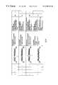
- the reconstructed signal 76 of one of the learning cycles, created in step 50is shown in FIG. 4 .
- the CPU 16performs the inverse wavelet packet transform on the feature wavelet packets, while setting the other packets to zero. Setting the other packets to zero eliminates noise from the signal.
- the reconstructed signal 76therefore comprises the principal components of the power consumption signal 28 , without the unwanted components such as various noises.
- the power threshold 78 created in step 52is shown in FIG. 5 .
- the power threshold 78is based upon statistical properties from the reconstructed power consumption signals 76 from the learning cycles.
- the power thresholdincludes an upper limit 80 and a lower limit 82 , which are both functions of time over the machine tool cycle.
- upper limit 80 and lower limit 82are preferably calculated as plus and minus five standard deviations, respectively, from the mean of the reconstructed power consumption signals 76 of the learning cycles.
- FIG. 5also shows one of the power consumption signals 76 from the learning cycles.
- the CPU 16compares the power consumption signal 76 from the learning cycles with the power threshold 78 to calculate means and standard deviations for number of crossings of the upper and lower limit 80 , 82 , time spent above the upper limit 80 , time spent below the lower limit 82 , and maximum and minimum instantaneous power consumption values.
- the power consumption signals from numerous learning cycleswould be compared with the power threshold 78 .
- the tool monitoring system 10After creating a power threshold 78 and threshold values, the tool monitoring system 10 enters the monitoring mode 90 , shown in FIG. 6 A.
- monitor mode 90the tool monitoring system 10 is again connected to a machine tool 18 of the selected tool type as shown in FIG. 1 .
- the same CPU 16is used in both the learning mode 40 and monitor mode 90 , however, it is recognized that the power threshold 78 data could be downloaded to a different CPU for the monitor mode.
- the learning modebe performed at the actual work station where the CPU will be monitoring. Using the actual A/D converter 14 for the learning mode signal acquisition will insure that any individual characteristics of the motor, tool mounts, etc. will be accounted for in the thresholds.
- step 92 of monitor mode 90the CPU 16 acquires and digitizes the power consumption signal of a machine tool 18 while the machine tool 18 performs its repetitive cyclical machining operations.
- step 96the power consumption signal is compared to the instantaneous maximum and minimum values calculated in the learning mode. If the power threshold signal falls between the minimum and maximum values, then the value _ma is set to equal 0. If the maximum value is exceeded, then _ma is set to equal 1. If the power consumption signal falls below the minimum value, _ma is set to 2. Finally, if the power consumption signal both exceeds the maximum value and falls below the minimum value, _ma is set to three.
- step 97the CPU 16 monitors the time that the power consumption signal is outside the power threshold, i.e. above the upper power threshold 80 and below the lower threshold 82 .
- step 98the CPU 16 counts the number of crossings by the power consumption signal of the upper and lower threshold limits 80 , 82 .
- step 100the values and numbers from steps 96 , 97 , 98 are compared to the threshold numbers. The times are compared to the threshold times. If the power consumption signal stays within the band, _cc is set to 0. If the power consumption signal stays below the lower limit of the power threshold 82 longer than the threshold time for the lower limit of the power threshold calculated in the learning mode, then _cc is set to 1. If the power consumption signal stays above the upper limit of the power threshold for time exceeding the threshold time for the upper limit of the power threshold calculated in the learning mode, then _cc is set to 2. If both times are exceeded, _cc is set to 3.
- step 100the numbers of crossings are compared to the threshold numbers. If the numbers of crossings is less than the threshold numbers of crossings calculated in the learning mode, then _cr is set to 0. If the number of crossings of the lower power threshold limit exceeds the threshold number of crossings of the lower threshold limit calculated in the learning mode, then _cr is set to 1. If the number of crossings of the upper threshold limit exceeds the threshold number of crossings of the upper power threshold limit, then _cr is set to 2. If both thresholds are exceeded, _cr is set to 3.
- a condition codeis calculated from the values for the three characteristics, _cr, _cc and _ma.
- step 103the control rule base is indexed based upon a weighting of the condition code values, which will be described in detail below with respect to FIG. 6 B. Based upon the condition code, the tool condition monitoring system 10 will turn on an appropriate condition indicator light 17 a-c , and may send a control command to stop the machine in step 104 .
- a different weightingis applied to the condition code utilizing an inference of tetradic and decimal transform.
- each of the characteristicssince each of the characteristics has one of four values, 0-3, each of the characteristics is multiplied by a different multiple of four.
- the value of _cris preferably multiplied by 4 2 , or 16.
- the value of _ccis preferably multiplied by 4 1 , or 4.
- the value of _mais preferably multiplied by 4 0 , or 1.
- the resultsare then added to provide a unique decimal number for each possible combination of values for the three characteristics. In the preferred embodiment illustrated here, one is added to the resulting number to eliminate a zero value. It should be apparent that if more characteristics are utilized, higher multiples of four would be utilized. Further, the base number, in this case four, is equal to the number of possible values. The base number could be increased to accommodate more possible values. This technique is illustrated below:
- diagnosis Rule 1is indexed.
- diagnosis Rule 21is indexed.
- the Rule calculated using above methodis then used to index a rule base in order to diagnose the condition of the machine tool 22 .
- the tool conditionis then indicated in step 108 , such by a display on CPU 16 of text indicating the condition of the tool 22 and possible problems.
- the rule basewill be described in detail below with respect to FIGS. 7-23.
- FIG. 6Bshows the control chart 110 for weighting the condition code to index a control rule base.
- the green light 17 a(of FIG. 1) is turned on and the “stop” command is turned off.
- _mais tested for a non-zero value. If the instantaneous maximum or minimum values are violated, the green light 17 a is immediately turned off, the red light 17 c is turned on and a stop command is sent to the machine to cease operation immediately in step 116 .
- _mais zero in step 114 , then _cr and _cc are tested for zero values. If both are zero, the CPU 16 returns to step 112 and the green light 17 a remains on. If _cc and _cr are not both zero, the sum of the squares is compared to 9. If the sum of the squares of _cc and _cr does not exceed 9, the green light is turned off and the yellow light 17 b is turned on in step 122 . If the sum of the squares of _cc and _cr exceeds 9, which can only occur if one of the values is three and the other is non-zero, the green light 17 a is turned off and the red light 17 c is turned on in step 124 . The CPU 16 returns to step 114 after step 122 or step 124 .
- the diagnosis rule base 130is shown in FIG. 7-23. As described above, the diagnosis rule base is indexed according to the possible values of the monitored characteristics _cr, _cc and _ma. As can be seen in FIG. 7, if _cr, _cc and _ma are all 0, Rule 1 is indexed, indicating that the tool is in a normal condition. If _cr equals 0, _cc equals 0, and _ma equals 1, Rule 2 of rule base 130 is indexed, thereby indicating that either the tool or the workpiece is loose and that the process should be stopped. The remaining Rules 3-64 are indexed in a similar manner according the weighting technique described above.
- the tool condition monitoring system 10 of the present inventionthus not only provides a warning of a worn or broken tool, but also diagnoses the present condition of the operation process based upon a plurality of characteristics of the power consumption signal.
Landscapes
- Engineering & Computer Science (AREA)
- Human Computer Interaction (AREA)
- Manufacturing & Machinery (AREA)
- Physics & Mathematics (AREA)
- General Physics & Mathematics (AREA)
- Automation & Control Theory (AREA)
- Testing And Monitoring For Control Systems (AREA)
- Numerical Control (AREA)
Abstract
Description
Claims (17)
Priority Applications (5)
| Application Number | Priority Date | Filing Date | Title |
|---|---|---|---|
| US08/901,609US6308138B1 (en) | 1997-07-28 | 1997-07-28 | Diagnostic rule base tool condition monitoring system |
| EP98934559AEP1004012A4 (en) | 1997-07-28 | 1998-07-15 | Diagnostic rule base tool condition monitoring system |
| CN98808722ACN1275198A (en) | 1997-07-28 | 1998-07-15 | Diagnosis Rule Base Tool Status Monitoring System |
| PCT/US1998/014623WO1999005501A1 (en) | 1997-07-28 | 1998-07-15 | Diagnostic rule base tool condition monitoring system |
| US09/200,017US6260427B1 (en) | 1997-07-28 | 1998-11-25 | Diagnostic rule tool condition monitoring system |
Applications Claiming Priority (1)
| Application Number | Priority Date | Filing Date | Title |
|---|---|---|---|
| US08/901,609US6308138B1 (en) | 1997-07-28 | 1997-07-28 | Diagnostic rule base tool condition monitoring system |
Related Child Applications (1)
| Application Number | Title | Priority Date | Filing Date |
|---|---|---|---|
| US09/200,017Continuation-In-PartUS6260427B1 (en) | 1997-07-28 | 1998-11-25 | Diagnostic rule tool condition monitoring system |
Publications (1)
| Publication Number | Publication Date |
|---|---|
| US6308138B1true US6308138B1 (en) | 2001-10-23 |
Family
ID=25414512
Family Applications (1)
| Application Number | Title | Priority Date | Filing Date |
|---|---|---|---|
| US08/901,609Expired - Fee RelatedUS6308138B1 (en) | 1997-07-28 | 1997-07-28 | Diagnostic rule base tool condition monitoring system |
Country Status (4)
| Country | Link |
|---|---|
| US (1) | US6308138B1 (en) |
| EP (1) | EP1004012A4 (en) |
| CN (1) | CN1275198A (en) |
| WO (1) | WO1999005501A1 (en) |
Cited By (30)
| Publication number | Priority date | Publication date | Assignee | Title |
|---|---|---|---|---|
| US6487506B1 (en)* | 1999-10-15 | 2002-11-26 | The Minster Machine Company | Thru-stroke tipping moment severity monitor |
| US6546814B1 (en) | 1999-03-13 | 2003-04-15 | Textron Systems Corporation | Method and apparatus for estimating torque in rotating machinery |
| US6594589B1 (en)* | 2001-05-23 | 2003-07-15 | Advanced Micro Devices, Inc. | Method and apparatus for monitoring tool health |
| US6604013B1 (en)* | 2000-10-11 | 2003-08-05 | Ford Motor Company | Tool failure detection utilizing frequency derived, pre-characterization templates |
| US6694285B1 (en)* | 1999-03-13 | 2004-02-17 | Textron System Corporation | Method and apparatus for monitoring rotating machinery |
| US6721675B1 (en)* | 2003-01-31 | 2004-04-13 | The Boeing Company | Machine capability verification and diagnostics (CAP/DIA) system, method and computer program product |
| US20040085193A1 (en)* | 2002-07-18 | 2004-05-06 | Crowell Brian R. | System and method for data retrieval in AC power tools via an AC line cord |
| US20040260514A1 (en)* | 2003-06-23 | 2004-12-23 | Benoit Beaudoin | System and software to monitor cyclic equipment efficiency and related methods |
| US20050011655A1 (en)* | 2003-07-16 | 2005-01-20 | Crowell Brian R. | System and method for data retrieval in AC power tools via an AC line cord |
| US20050043923A1 (en)* | 2003-08-19 | 2005-02-24 | Festo Corporation | Method and apparatus for diagnosing a cyclic system |
| US20050234660A1 (en)* | 2004-04-16 | 2005-10-20 | Festo Corporation | Method and apparatus for diagnosing leakage in a fluid power system |
| US20060047403A1 (en)* | 2004-08-26 | 2006-03-02 | Volponi Allan J | System for gas turbine health monitoring data fusion |
| US20060101897A1 (en)* | 2004-11-12 | 2006-05-18 | Fanuc Ltd | Impact detection device |
| US20060197841A1 (en)* | 2005-01-05 | 2006-09-07 | Jenn-Shoou Young | Self-diagnostic method and device for digital televicion |
| US20070291438A1 (en)* | 2006-06-16 | 2007-12-20 | Oliver Ahrens | Method and apparatus for monitoring and determining the functional status of an electromagnetic valve |
| US20100264867A1 (en)* | 2009-04-17 | 2010-10-21 | Fanuc Ltd | Control device for machine tool |
| US7970722B1 (en) | 1999-11-08 | 2011-06-28 | Aloft Media, Llc | System, method and computer program product for a collaborative decision platform |
| US20110316335A1 (en)* | 2009-12-17 | 2011-12-29 | Siemens Aktiengesellschaft | Method and device for operating an automation machine |
| US8374823B1 (en)* | 2004-02-19 | 2013-02-12 | Oracle America, Inc. | Method and apparatus for monitoring variations in a parameter over time |
| US20140107853A1 (en)* | 2012-06-26 | 2014-04-17 | Black & Decker Inc. | System for enhancing power tools |
| CN104076796A (en)* | 2014-07-07 | 2014-10-01 | 蓝星(北京)技术中心有限公司 | Method and device for evaluating health condition of dicing cutter in real time and dicing cutter |
| US20160253230A1 (en)* | 2015-02-26 | 2016-09-01 | Alibaba Group Holding Limited | Method and apparatus for predicting gpu malfunctions |
| US20180113447A1 (en)* | 2015-04-29 | 2018-04-26 | Packsize Llc | Profiling of packaging systems |
| US10195708B2 (en)* | 2016-09-28 | 2019-02-05 | The Boeing Company | Method and apparatus for centralized compliance, operations and setup of automated cutting tool machines |
| US11009431B2 (en)* | 2017-11-28 | 2021-05-18 | Hitachi, Ltd. | Failure mode specifying system, failure mode specifying method, and program |
| US20210339352A1 (en)* | 2018-12-27 | 2021-11-04 | Its Co., Ltd. | Method of detecting integrity index of machine tool |
| US11221611B2 (en) | 2018-01-24 | 2022-01-11 | Milwaukee Electric Tool Corporation | Power tool including a machine learning block |
| US12111621B2 (en) | 2019-07-23 | 2024-10-08 | Milwaukee Electric Tool Corporation | Power tool including a machine learning block for controlling a seating of a fastener |
| IT202300013071A1 (en)* | 2023-06-23 | 2024-12-23 | Machining Centers Mfg S P A Oppure Mcm S P A | METHOD FOR ESTIMATE THE STATE OF A TOOL DURING A CHIP REMOVAL OPERATION |
| US12434343B2 (en) | 2018-11-06 | 2025-10-07 | Rochester Institute Of Technology | Calibration-based tool condition monitoring system for repetitive machining operations |
Families Citing this family (8)
| Publication number | Priority date | Publication date | Assignee | Title |
|---|---|---|---|---|
| SE523087C2 (en) | 2002-05-08 | 2004-03-23 | Psd Insight Ab | Method and apparatus for diagnosing the function of moving mechanical parts with a power signature in a mechanical device |
| US10185304B2 (en) | 2012-03-21 | 2019-01-22 | Delcam Limited | Timing a machine tool using an accelerometer |
| GB201204908D0 (en)* | 2012-03-21 | 2012-05-02 | Delcam Plc | Method and system for testing a machine tool |
| JP6617474B2 (en)* | 2015-08-31 | 2019-12-11 | ブラザー工業株式会社 | Numerical control device and control method |
| CN105738137A (en)* | 2016-02-02 | 2016-07-06 | 安徽农业大学 | Farm machinery cutter energy consumption data acquiring and analyzing method |
| CN105867305B (en)* | 2016-05-13 | 2018-06-12 | 南京航空航天大学 | Complex structural member digital control processing realtime monitoring method based on machining feature |
| CN111122083B (en)* | 2019-12-16 | 2021-02-23 | 珠海格力电器股份有限公司 | Cutter detection method and device, electronic equipment and readable medium |
| SE544532C2 (en) | 2020-12-18 | 2022-07-05 | Husqvarna Ab | Improved fault detection methods for power tools |
Citations (14)
| Publication number | Priority date | Publication date | Assignee | Title |
|---|---|---|---|---|
| US3694637A (en) | 1970-10-22 | 1972-09-26 | Interactive Systems | Method and apparatus for detecting tool wear |
| US4351029A (en) | 1979-12-05 | 1982-09-21 | Westinghouse Electric Corp. | Tool life monitoring and tracking apparatus |
| US4471444A (en) | 1982-04-02 | 1984-09-11 | The United States Of America As Represented By The Secretary Of Commerce | Rotating tool wear monitoring apparatus |
| US4658245A (en)* | 1983-04-29 | 1987-04-14 | The Warner & Swasey Company | Tool condition and failure monitoring apparatus and method |
| US4748554A (en) | 1986-08-14 | 1988-05-31 | Gte Valeron Corporation | Machine monitoring system using motion detection for synchronization |
| US5070655A (en)* | 1990-11-30 | 1991-12-10 | Aggarwal Trilok R | Machining process monitor |
| US5210704A (en)* | 1990-10-02 | 1993-05-11 | Technology International Incorporated | System for prognosis and diagnostics of failure and wearout monitoring and for prediction of life expectancy of helicopter gearboxes and other rotating equipment |
| US5247452A (en) | 1990-05-31 | 1993-09-21 | Ntn Corporation | Controller for cutting machine |
| US5251144A (en)* | 1991-04-18 | 1993-10-05 | Texas Instruments Incorporated | System and method utilizing a real time expert system for tool life prediction and tool wear diagnosis |
| US5407265A (en) | 1992-07-06 | 1995-04-18 | Ford Motor Company | System and method for detecting cutting tool failure |
| US5566092A (en)* | 1993-12-30 | 1996-10-15 | Caterpillar Inc. | Machine fault diagnostics system and method |
| US5587931A (en) | 1995-10-20 | 1996-12-24 | Tri-Way Machine Ltd. | Tool condition monitoring system |
| US5857166A (en)* | 1996-08-30 | 1999-01-05 | Kim; Nam H. | Tool monitoring apparatus |
| US5921726A (en)* | 1996-04-23 | 1999-07-13 | Toshiba Kikai Kabushiki Kaisha | Machine tool with worn-detection function for tool |
Family Cites Families (5)
| Publication number | Priority date | Publication date | Assignee | Title |
|---|---|---|---|---|
| US4228514A (en)* | 1979-04-16 | 1980-10-14 | Bell Telephone Laboratories, Incorporated | Method and system for determining the wear of a drill bit in real time |
| JPS62281789A (en)* | 1986-05-30 | 1987-12-07 | Toshiba Corp | Equipment equipment diagnosis device |
| US5612601A (en)* | 1993-11-22 | 1997-03-18 | Martin Marietta Energy Systems, Inc. | Method for assessing motor insulation on operating motors |
| US5627759A (en)* | 1995-05-31 | 1997-05-06 | Process Systems, Inc. | Electrical energy meters having real-time power quality measurement and reporting capability |
| GB2302952A (en)* | 1995-07-06 | 1997-02-05 | C & C Technology Enterprises | Electrical power consumption control and evaluation system |
- 1997
- 1997-07-28USUS08/901,609patent/US6308138B1/ennot_activeExpired - Fee Related
- 1998
- 1998-07-15EPEP98934559Apatent/EP1004012A4/ennot_activeWithdrawn
- 1998-07-15CNCN98808722Apatent/CN1275198A/enactivePending
- 1998-07-15WOPCT/US1998/014623patent/WO1999005501A1/ennot_activeApplication Discontinuation
Patent Citations (14)
| Publication number | Priority date | Publication date | Assignee | Title |
|---|---|---|---|---|
| US3694637A (en) | 1970-10-22 | 1972-09-26 | Interactive Systems | Method and apparatus for detecting tool wear |
| US4351029A (en) | 1979-12-05 | 1982-09-21 | Westinghouse Electric Corp. | Tool life monitoring and tracking apparatus |
| US4471444A (en) | 1982-04-02 | 1984-09-11 | The United States Of America As Represented By The Secretary Of Commerce | Rotating tool wear monitoring apparatus |
| US4658245A (en)* | 1983-04-29 | 1987-04-14 | The Warner & Swasey Company | Tool condition and failure monitoring apparatus and method |
| US4748554A (en) | 1986-08-14 | 1988-05-31 | Gte Valeron Corporation | Machine monitoring system using motion detection for synchronization |
| US5247452A (en) | 1990-05-31 | 1993-09-21 | Ntn Corporation | Controller for cutting machine |
| US5210704A (en)* | 1990-10-02 | 1993-05-11 | Technology International Incorporated | System for prognosis and diagnostics of failure and wearout monitoring and for prediction of life expectancy of helicopter gearboxes and other rotating equipment |
| US5070655A (en)* | 1990-11-30 | 1991-12-10 | Aggarwal Trilok R | Machining process monitor |
| US5251144A (en)* | 1991-04-18 | 1993-10-05 | Texas Instruments Incorporated | System and method utilizing a real time expert system for tool life prediction and tool wear diagnosis |
| US5407265A (en) | 1992-07-06 | 1995-04-18 | Ford Motor Company | System and method for detecting cutting tool failure |
| US5566092A (en)* | 1993-12-30 | 1996-10-15 | Caterpillar Inc. | Machine fault diagnostics system and method |
| US5587931A (en) | 1995-10-20 | 1996-12-24 | Tri-Way Machine Ltd. | Tool condition monitoring system |
| US5921726A (en)* | 1996-04-23 | 1999-07-13 | Toshiba Kikai Kabushiki Kaisha | Machine tool with worn-detection function for tool |
| US5857166A (en)* | 1996-08-30 | 1999-01-05 | Kim; Nam H. | Tool monitoring apparatus |
Non-Patent Citations (1)
| Title |
|---|
| Feature Extraction and Assessment Using Wavelet Packets for Monitoring of MachIning Processes by Dr. Ya Wu and R. Du, (No Date). |
Cited By (51)
| Publication number | Priority date | Publication date | Assignee | Title |
|---|---|---|---|---|
| US6546814B1 (en) | 1999-03-13 | 2003-04-15 | Textron Systems Corporation | Method and apparatus for estimating torque in rotating machinery |
| US6694285B1 (en)* | 1999-03-13 | 2004-02-17 | Textron System Corporation | Method and apparatus for monitoring rotating machinery |
| US6487506B1 (en)* | 1999-10-15 | 2002-11-26 | The Minster Machine Company | Thru-stroke tipping moment severity monitor |
| US8160988B1 (en) | 1999-11-08 | 2012-04-17 | Aloft Media, Llc | System, method and computer program product for a collaborative decision platform |
| US7970722B1 (en) | 1999-11-08 | 2011-06-28 | Aloft Media, Llc | System, method and computer program product for a collaborative decision platform |
| US8005777B1 (en) | 1999-11-08 | 2011-08-23 | Aloft Media, Llc | System, method and computer program product for a collaborative decision platform |
| US6604013B1 (en)* | 2000-10-11 | 2003-08-05 | Ford Motor Company | Tool failure detection utilizing frequency derived, pre-characterization templates |
| US6594589B1 (en)* | 2001-05-23 | 2003-07-15 | Advanced Micro Devices, Inc. | Method and apparatus for monitoring tool health |
| US20060195202A1 (en)* | 2002-07-18 | 2006-08-31 | Brotto Daniele C | System and method for data retrieval in AC power tools via an AC line cord |
| US7346406B2 (en) | 2002-07-18 | 2008-03-18 | Black & Decker Inc. | System and method for data retrieval in AC power tools via an AC line cord |
| US20040085193A1 (en)* | 2002-07-18 | 2004-05-06 | Crowell Brian R. | System and method for data retrieval in AC power tools via an AC line cord |
| US7054696B2 (en) | 2002-07-18 | 2006-05-30 | Black & Decker Inc. | System and method for data retrieval in AC power tools via an AC line cord |
| US20040153273A1 (en)* | 2003-01-31 | 2004-08-05 | Chawla Mohinder P. | Machine capability verification and diagnostics (CAP/DIA) system, method and computer program product |
| US6847908B2 (en) | 2003-01-31 | 2005-01-25 | The Boeing Company | Machine capability verification and diagnostics (CAP/DIA) system, method and computer program product |
| US6721675B1 (en)* | 2003-01-31 | 2004-04-13 | The Boeing Company | Machine capability verification and diagnostics (CAP/DIA) system, method and computer program product |
| US6990431B2 (en) | 2003-06-23 | 2006-01-24 | Municipal And Industrial Data Labs, Inc. | System and software to monitor cyclic equipment efficiency and related methods |
| US20040260514A1 (en)* | 2003-06-23 | 2004-12-23 | Benoit Beaudoin | System and software to monitor cyclic equipment efficiency and related methods |
| US20050011655A1 (en)* | 2003-07-16 | 2005-01-20 | Crowell Brian R. | System and method for data retrieval in AC power tools via an AC line cord |
| US7330129B2 (en) | 2003-07-16 | 2008-02-12 | Black & Decker Inc. | System and method for data retrieval in AC power tools via an AC line cord |
| US20050043923A1 (en)* | 2003-08-19 | 2005-02-24 | Festo Corporation | Method and apparatus for diagnosing a cyclic system |
| US7124057B2 (en) | 2003-08-19 | 2006-10-17 | Festo Corporation | Method and apparatus for diagnosing a cyclic system |
| US8374823B1 (en)* | 2004-02-19 | 2013-02-12 | Oracle America, Inc. | Method and apparatus for monitoring variations in a parameter over time |
| US20050234660A1 (en)* | 2004-04-16 | 2005-10-20 | Festo Corporation | Method and apparatus for diagnosing leakage in a fluid power system |
| US7031850B2 (en) | 2004-04-16 | 2006-04-18 | Festo Ag & Co. Kg | Method and apparatus for diagnosing leakage in a fluid power system |
| US7769507B2 (en)* | 2004-08-26 | 2010-08-03 | United Technologies Corporation | System for gas turbine health monitoring data fusion |
| US20060047403A1 (en)* | 2004-08-26 | 2006-03-02 | Volponi Allan J | System for gas turbine health monitoring data fusion |
| US20060101897A1 (en)* | 2004-11-12 | 2006-05-18 | Fanuc Ltd | Impact detection device |
| US20060197841A1 (en)* | 2005-01-05 | 2006-09-07 | Jenn-Shoou Young | Self-diagnostic method and device for digital televicion |
| US7405917B2 (en) | 2006-06-16 | 2008-07-29 | Festo Ag & Co. | Method and apparatus for monitoring and determining the functional status of an electromagnetic valve |
| US20070291438A1 (en)* | 2006-06-16 | 2007-12-20 | Oliver Ahrens | Method and apparatus for monitoring and determining the functional status of an electromagnetic valve |
| US20100264867A1 (en)* | 2009-04-17 | 2010-10-21 | Fanuc Ltd | Control device for machine tool |
| US8026689B2 (en)* | 2009-04-17 | 2011-09-27 | Fanuc Ltd | Control device for machine tool |
| US20110316335A1 (en)* | 2009-12-17 | 2011-12-29 | Siemens Aktiengesellschaft | Method and device for operating an automation machine |
| US20140107853A1 (en)* | 2012-06-26 | 2014-04-17 | Black & Decker Inc. | System for enhancing power tools |
| CN104076796A (en)* | 2014-07-07 | 2014-10-01 | 蓝星(北京)技术中心有限公司 | Method and device for evaluating health condition of dicing cutter in real time and dicing cutter |
| CN104076796B (en)* | 2014-07-07 | 2017-01-11 | 蓝星(北京)技术中心有限公司 | Method and device for evaluating health condition of dicing cutter in real time and dicing cutter |
| CN105988918A (en)* | 2015-02-26 | 2016-10-05 | 阿里巴巴集团控股有限公司 | GPU fault prediction method and device |
| US20160253230A1 (en)* | 2015-02-26 | 2016-09-01 | Alibaba Group Holding Limited | Method and apparatus for predicting gpu malfunctions |
| US10031797B2 (en)* | 2015-02-26 | 2018-07-24 | Alibaba Group Holding Limited | Method and apparatus for predicting GPU malfunctions |
| CN105988918B (en)* | 2015-02-26 | 2019-03-08 | 阿里巴巴集团控股有限公司 | The method and apparatus for predicting GPU failure |
| WO2016138375A1 (en)* | 2015-02-26 | 2016-09-01 | Alibaba Group Holding Limited | Method and apparatus for predicting gpu malfunctions |
| US11194322B2 (en)* | 2015-04-29 | 2021-12-07 | Packsize Llc | Profiling of packaging systems |
| US20180113447A1 (en)* | 2015-04-29 | 2018-04-26 | Packsize Llc | Profiling of packaging systems |
| US10195708B2 (en)* | 2016-09-28 | 2019-02-05 | The Boeing Company | Method and apparatus for centralized compliance, operations and setup of automated cutting tool machines |
| US11009431B2 (en)* | 2017-11-28 | 2021-05-18 | Hitachi, Ltd. | Failure mode specifying system, failure mode specifying method, and program |
| US11221611B2 (en) | 2018-01-24 | 2022-01-11 | Milwaukee Electric Tool Corporation | Power tool including a machine learning block |
| US12153402B2 (en) | 2018-01-24 | 2024-11-26 | Milwaukee Electric Tool Corporation | Power tool including a machine learning block |
| US12434343B2 (en) | 2018-11-06 | 2025-10-07 | Rochester Institute Of Technology | Calibration-based tool condition monitoring system for repetitive machining operations |
| US20210339352A1 (en)* | 2018-12-27 | 2021-11-04 | Its Co., Ltd. | Method of detecting integrity index of machine tool |
| US12111621B2 (en) | 2019-07-23 | 2024-10-08 | Milwaukee Electric Tool Corporation | Power tool including a machine learning block for controlling a seating of a fastener |
| IT202300013071A1 (en)* | 2023-06-23 | 2024-12-23 | Machining Centers Mfg S P A Oppure Mcm S P A | METHOD FOR ESTIMATE THE STATE OF A TOOL DURING A CHIP REMOVAL OPERATION |
Also Published As
| Publication number | Publication date |
|---|---|
| EP1004012A4 (en) | 2001-01-24 |
| WO1999005501A1 (en) | 1999-02-04 |
| CN1275198A (en) | 2000-11-29 |
| EP1004012A1 (en) | 2000-05-31 |
Similar Documents
| Publication | Publication Date | Title |
|---|---|---|
| US6308138B1 (en) | Diagnostic rule base tool condition monitoring system | |
| US6260427B1 (en) | Diagnostic rule tool condition monitoring system | |
| US5587931A (en) | Tool condition monitoring system | |
| US5407265A (en) | System and method for detecting cutting tool failure | |
| FI112972B (en) | Assessment of stock condition | |
| US20150346066A1 (en) | Asset Condition Monitoring | |
| JPS58500605A (en) | Method and device for monitoring tool status of a machine tool that performs periodic machining | |
| KR102719373B1 (en) | Iot based intelligent monitoring and diagnosis method and device for machine tool | |
| EP1348296B1 (en) | Control embedded machine condition monitor | |
| CN118277939B (en) | Ship cutting machine operation fault diagnosis system based on machine vision | |
| Ginart et al. | Automated feature selection for embeddable prognostic and health monitoring (PHM) architectures | |
| CN112711850A (en) | Unit online monitoring method based on big data | |
| CN110696990B (en) | Ship generator component influence identification method and system based on data driving | |
| EP0842006B1 (en) | Tool condition monitoring system | |
| CN118466396A (en) | Machine tool equipment fault early warning method and system based on data analysis | |
| CN118629104A (en) | Engine status monitoring alarm system and method | |
| CA2162433C (en) | Tool condition monitoring system | |
| JPH11258381A (en) | Detector abnormality diagnostic method | |
| RU2826825C1 (en) | Device for monitoring the technical state of an electrical machine | |
| CN119738709B (en) | A post-use detection and early warning system and method for construction equipment | |
| CN120708655A (en) | Motor fault diagnosis method and system based on voiceprint feature and variable frequency parameter linkage | |
| CN117434360A (en) | Switch action current curve matching alarm method, system and medium | |
| CN119245747A (en) | A circular vibrating screen operation fault monitoring system and method | |
| CN118464445A (en) | Rotary machine fault diagnosis method based on multi-operation mode rule base diagnosis strategy | |
| Hancock et al. | A Hybrid Approach to Hydraulic Vane Pump Health Monitoring and Fault Detection |
Legal Events
| Date | Code | Title | Description |
|---|---|---|---|
| AS | Assignment | Owner name:TRI-WAY MACHINE LTD., CANADA Free format text:ASSIGNMENT OF ASSIGNORS INTEREST;ASSIGNORS:JONES, JOEL W.;WU, YA;REEL/FRAME:009087/0684 Effective date:19980217 | |
| AS | Assignment | Owner name:WILMINGTON TRUST COMPANY, AS TRUSTEE, DELAWARE Free format text:SECURITY INTEREST;ASSIGNOR:FEDERAL-MOGUL WORLD WIDE, INC. (MI CORPORATION);REEL/FRAME:011466/0001 Effective date:20001229 | |
| FEPP | Fee payment procedure | Free format text:PAYOR NUMBER ASSIGNED (ORIGINAL EVENT CODE: ASPN); ENTITY STATUS OF PATENT OWNER: LARGE ENTITY | |
| AS | Assignment | Owner name:3060367 NOVA SCOTIA COMPANY, CANADA Free format text:PATENT LICENSE AND ASSIGNMENT AGREEMENT;ASSIGNOR:FEDERAL-MOGUL TRI-WAY LTD.;REEL/FRAME:012754/0636 Effective date:20010921 | |
| AS | Assignment | Owner name:3060367 NOVA SCOTIA COMPANY, ONTARIO Free format text:SECURITY INTEREST;ASSIGNOR:FEDERAL-MOGUL TRI-WAY LTD.;REEL/FRAME:013056/0112 Effective date:20020520 | |
| CC | Certificate of correction | ||
| REMI | Maintenance fee reminder mailed | ||
| AS | Assignment | Owner name:TRI-WAY MANUFACTURING TECHNOLOGIES CORP., CANADA Free format text:CHANGE OF NAME;ASSIGNOR:NOVA SCOTIA COMPANY;REEL/FRAME:016651/0830 Effective date:20011024 | |
| LAPS | Lapse for failure to pay maintenance fees | ||
| STCH | Information on status: patent discontinuation | Free format text:PATENT EXPIRED DUE TO NONPAYMENT OF MAINTENANCE FEES UNDER 37 CFR 1.362 | |
| FP | Lapsed due to failure to pay maintenance fee | Effective date:20051023 |