US6307853B1 - Re-routing telephony communications traffic through a private branch exchange to a data network - Google Patents
Re-routing telephony communications traffic through a private branch exchange to a data networkDownload PDFInfo
- Publication number
- US6307853B1 US6307853B1US08/936,830US93683097AUS6307853B1US 6307853 B1US6307853 B1US 6307853B1US 93683097 AUS93683097 AUS 93683097AUS 6307853 B1US6307853 B1US 6307853B1
- Authority
- US
- United States
- Prior art keywords
- data
- telephony
- telephone
- tdr
- routing
- Prior art date
- Legal status (The legal status is an assumption and is not a legal conclusion. Google has not performed a legal analysis and makes no representation as to the accuracy of the status listed.)
- Expired - Lifetime
Links
- 238000004891communicationMethods0.000titleclaimsabstractdescription59
- 238000000034methodMethods0.000claimsabstractdescription34
- 230000005540biological transmissionEffects0.000claimsabstractdescription19
- 238000012384transportation and deliveryMethods0.000claimsabstractdescription11
- 230000006835compressionEffects0.000claimsdescription8
- 238000007906compressionMethods0.000claimsdescription8
- 230000008901benefitEffects0.000abstractdescription7
- 230000008569processEffects0.000abstractdescription4
- 230000004044responseEffects0.000abstractdescription2
- 230000008859changeEffects0.000description7
- 230000004048modificationEffects0.000description7
- 238000012986modificationMethods0.000description7
- 238000012546transferMethods0.000description4
- 238000006243chemical reactionMethods0.000description3
- 230000006870functionEffects0.000description3
- 230000000977initiatory effectEffects0.000description3
- 238000012423maintenanceMethods0.000description3
- 238000007726management methodMethods0.000description3
- 238000009434installationMethods0.000description2
- 238000013468resource allocationMethods0.000description2
- 241000277284Salvelinus fontinalisSpecies0.000description1
- 238000013475authorizationMethods0.000description1
- 230000003111delayed effectEffects0.000description1
- 230000000694effectsEffects0.000description1
- 239000000284extractSubstances0.000description1
- 230000006872improvementEffects0.000description1
- 238000005457optimizationMethods0.000description1
- 238000003825pressingMethods0.000description1
- 230000011664signalingEffects0.000description1
- 230000000153supplemental effectEffects0.000description1
- 230000001360synchronised effectEffects0.000description1
- 238000012549trainingMethods0.000description1
- 230000007723transport mechanismEffects0.000description1
Images


Classifications
- H—ELECTRICITY
- H04—ELECTRIC COMMUNICATION TECHNIQUE
- H04M—TELEPHONIC COMMUNICATION
- H04M7/00—Arrangements for interconnection between switching centres
- H04M7/0024—Services and arrangements where telephone services are combined with data services
- H04M7/0057—Services where the data services network provides a telephone service in addition or as an alternative, e.g. for backup purposes, to the telephone service provided by the telephone services network
- H—ELECTRICITY
- H04—ELECTRIC COMMUNICATION TECHNIQUE
- H04L—TRANSMISSION OF DIGITAL INFORMATION, e.g. TELEGRAPHIC COMMUNICATION
- H04L12/00—Data switching networks
- H04L12/54—Store-and-forward switching systems
- H04L12/56—Packet switching systems
- H04L12/5691—Access to open networks; Ingress point selection, e.g. ISP selection
- H04L12/5692—Selection among different networks
- H—ELECTRICITY
- H04—ELECTRIC COMMUNICATION TECHNIQUE
- H04M—TELEPHONIC COMMUNICATION
- H04M15/00—Arrangements for metering, time-control or time indication ; Metering, charging or billing arrangements for voice wireline or wireless communications, e.g. VoIP
- H—ELECTRICITY
- H04—ELECTRIC COMMUNICATION TECHNIQUE
- H04M—TELEPHONIC COMMUNICATION
- H04M15/00—Arrangements for metering, time-control or time indication ; Metering, charging or billing arrangements for voice wireline or wireless communications, e.g. VoIP
- H04M15/49—Connection to several service providers
- H—ELECTRICITY
- H04—ELECTRIC COMMUNICATION TECHNIQUE
- H04M—TELEPHONIC COMMUNICATION
- H04M15/00—Arrangements for metering, time-control or time indication ; Metering, charging or billing arrangements for voice wireline or wireless communications, e.g. VoIP
- H04M15/56—Arrangements for metering, time-control or time indication ; Metering, charging or billing arrangements for voice wireline or wireless communications, e.g. VoIP for VoIP communications
- H—ELECTRICITY
- H04—ELECTRIC COMMUNICATION TECHNIQUE
- H04M—TELEPHONIC COMMUNICATION
- H04M15/00—Arrangements for metering, time-control or time indication ; Metering, charging or billing arrangements for voice wireline or wireless communications, e.g. VoIP
- H04M15/80—Rating or billing plans; Tariff determination aspects
- H04M15/8044—Least cost routing
- H—ELECTRICITY
- H04—ELECTRIC COMMUNICATION TECHNIQUE
- H04Q—SELECTING
- H04Q3/00—Selecting arrangements
- H04Q3/64—Distributing or queueing
- H04Q3/66—Traffic distributors
- H—ELECTRICITY
- H04—ELECTRIC COMMUNICATION TECHNIQUE
- H04L—TRANSMISSION OF DIGITAL INFORMATION, e.g. TELEGRAPHIC COMMUNICATION
- H04L63/00—Network architectures or network communication protocols for network security
- H04L63/04—Network architectures or network communication protocols for network security for providing a confidential data exchange among entities communicating through data packet networks
- H04L63/0428—Network architectures or network communication protocols for network security for providing a confidential data exchange among entities communicating through data packet networks wherein the data content is protected, e.g. by encrypting or encapsulating the payload
- H—ELECTRICITY
- H04—ELECTRIC COMMUNICATION TECHNIQUE
- H04L—TRANSMISSION OF DIGITAL INFORMATION, e.g. TELEGRAPHIC COMMUNICATION
- H04L63/00—Network architectures or network communication protocols for network security
- H04L63/08—Network architectures or network communication protocols for network security for authentication of entities
- H—ELECTRICITY
- H04—ELECTRIC COMMUNICATION TECHNIQUE
- H04M—TELEPHONIC COMMUNICATION
- H04M2215/00—Metering arrangements; Time controlling arrangements; Time indicating arrangements
- H04M2215/20—Technology dependant metering
- H04M2215/202—VoIP; Packet switched telephony
- H—ELECTRICITY
- H04—ELECTRIC COMMUNICATION TECHNIQUE
- H04M—TELEPHONIC COMMUNICATION
- H04M2215/00—Metering arrangements; Time controlling arrangements; Time indicating arrangements
- H04M2215/42—Least cost routing, i.e. provision for selecting the lowest cost tariff
- H—ELECTRICITY
- H04—ELECTRIC COMMUNICATION TECHNIQUE
- H04M—TELEPHONIC COMMUNICATION
- H04M2215/00—Metering arrangements; Time controlling arrangements; Time indicating arrangements
- H04M2215/46—Connection to several service providers
- H—ELECTRICITY
- H04—ELECTRIC COMMUNICATION TECHNIQUE
- H04M—TELEPHONIC COMMUNICATION
- H04M2215/00—Metering arrangements; Time controlling arrangements; Time indicating arrangements
- H04M2215/74—Rating aspects, e.g. rating parameters or tariff determination apects
- H04M2215/745—Least cost routing, e.g. Automatic or manual, call by call or by preselection
- H—ELECTRICITY
- H04—ELECTRIC COMMUNICATION TECHNIQUE
- H04Q—SELECTING
- H04Q2213/00—Indexing scheme relating to selecting arrangements in general and for multiplex systems
- H04Q2213/13096—Digital apparatus individually associated with a subscriber line, digital line circuits
- H—ELECTRICITY
- H04—ELECTRIC COMMUNICATION TECHNIQUE
- H04Q—SELECTING
- H04Q2213/00—Indexing scheme relating to selecting arrangements in general and for multiplex systems
- H04Q2213/13138—Least cost routing, LCR
- H—ELECTRICITY
- H04—ELECTRIC COMMUNICATION TECHNIQUE
- H04Q—SELECTING
- H04Q2213/00—Indexing scheme relating to selecting arrangements in general and for multiplex systems
- H04Q2213/13141—Hunting for free outlet, circuit or channel
- H—ELECTRICITY
- H04—ELECTRIC COMMUNICATION TECHNIQUE
- H04Q—SELECTING
- H04Q2213/00—Indexing scheme relating to selecting arrangements in general and for multiplex systems
- H04Q2213/13179—Fax, still picture
- H—ELECTRICITY
- H04—ELECTRIC COMMUNICATION TECHNIQUE
- H04Q—SELECTING
- H04Q2213/00—Indexing scheme relating to selecting arrangements in general and for multiplex systems
- H04Q2213/13204—Protocols
- H—ELECTRICITY
- H04—ELECTRIC COMMUNICATION TECHNIQUE
- H04Q—SELECTING
- H04Q2213/00—Indexing scheme relating to selecting arrangements in general and for multiplex systems
- H04Q2213/1322—PBX
- H—ELECTRICITY
- H04—ELECTRIC COMMUNICATION TECHNIQUE
- H04Q—SELECTING
- H04Q2213/00—Indexing scheme relating to selecting arrangements in general and for multiplex systems
- H04Q2213/13298—Local loop systems, access network
- H—ELECTRICITY
- H04—ELECTRIC COMMUNICATION TECHNIQUE
- H04Q—SELECTING
- H04Q2213/00—Indexing scheme relating to selecting arrangements in general and for multiplex systems
- H04Q2213/13332—Broadband, CATV, dynamic bandwidth allocation
- H—ELECTRICITY
- H04—ELECTRIC COMMUNICATION TECHNIQUE
- H04Q—SELECTING
- H04Q2213/00—Indexing scheme relating to selecting arrangements in general and for multiplex systems
- H04Q2213/13336—Store & forward, messaging systems
- H—ELECTRICITY
- H04—ELECTRIC COMMUNICATION TECHNIQUE
- H04Q—SELECTING
- H04Q2213/00—Indexing scheme relating to selecting arrangements in general and for multiplex systems
- H04Q2213/13339—Ciphering, encryption, security
- H—ELECTRICITY
- H04—ELECTRIC COMMUNICATION TECHNIQUE
- H04Q—SELECTING
- H04Q2213/00—Indexing scheme relating to selecting arrangements in general and for multiplex systems
- H04Q2213/13352—Self-routing networks, real-time routing
- H—ELECTRICITY
- H04—ELECTRIC COMMUNICATION TECHNIQUE
- H04Q—SELECTING
- H04Q2213/00—Indexing scheme relating to selecting arrangements in general and for multiplex systems
- H04Q2213/13389—LAN, internet
Definitions
- the present inventionrelates to routing telephony communications. More specifically, the present invention relates to re-routing telephony communications over a data network or over a public switched telephone network (PSTN).
- PSTNpublic switched telephone network
- the first class of conventional routing systemsuses “re-dialers”.
- Re-dialersre-route specific calls through a separate transmission path, e.g., a data network, using a real-time or store-and-forward transport mechanism.
- the re-dialersare placed between an originating telephony device (most typically a fax machine) and a public switched telephone network (PSTN) or private branch exchange (PBX).
- PSTNpublic switched telephone network
- PBXprivate branch exchange
- FIG. 1illustrates a fax machine 101 connected to a re-dialer 102 .
- the re-dialeris connected to a PSTN point of presence (POP) 201 .
- the re-dialer 102is also connected to a wide area network (WAN) POP 301 .
- the PSTN POP 201serves as a gateway to the PSTN 200 .
- the WAN POP 301serves as a gateway to the WAN 300 .
- a fax machine 103can receive a fax transmission from fax machine 101 . It should be noted that, in the general sense, the fax machine 103 can transmit a fax as well as receive a fax.
- the fax machine 103receives the fax from either a PSTN POP 202 (if the fax is transmitted over the PSTN 200 ) or a WAN POP 302 (if the fax is transmitted over the WAN 300 ).
- the PSTN POP 202is similar in operation to PSTN POP 201 .
- the WAN POP 302is similar in operation to the WAN POP 301 .
- the re-dialer 102can re-route any fax call through a data network rather than through a PSTN 200 .
- a data networkcan be a private wide-area network, a shared wide-area network such as could be provided by a value-added network service provider, an intranet, the internet, or any combination of these.
- Such a data networkis showing in FIG. 1 as WAN 300 .
- Re-routingcan be based on the phone number dialed or other telephony condition (e.g., receiver busy). If re-routed, a fax machine 101 communicates with a fax machine 103 through the data network rather than through the PSTN 200 .
- the communicationcan be conducted in real-time or can be delayed, e.g., by store and forward delivery.
- this first class of conventional routing systemsrequires a re-dialer for each telephone device, which is a significant drawback.
- the second class of conventional routing systemsprovides real-time voice communications from and to computer systems which have analog-to-data hardware and appropriate software. Though currently popular on the Internet, the second class of conventional routing systems can be implemented on any data network.
- the second class of conventional routing systemsis shown schematically in FIG. 2.
- a workstation user 104communicates with a workstation user 105 through the WAN 300 .
- Recent modifications to the second class of conventional routing systemsallow the receiver of the phone call, the user 105 , to use a telephone rather than a computer workstation.
- the primary drawback to the second class of conventional routing systemsis that the call originator must change his or her telephony interface. In the case of voice calls, for example, the change requires that the call originator speak and listen through a computer system instead of through a telephone.
- a fairly straightforward modification of the second class of conventional routing systemsis to have the call originator dial directly into a WAN POP 301 from a telephone. This modification also requires the user to dial one number for connection, identify himself or herself for authorization purposes, and then identify the receiver's address (i.e., workstation identifier or telephone number.) i.e., Thus, the modification requires the user to change the user's interface.
- any solution that requires a modification of an existing user interfacepresents a training and acceptance challenge. Users have shown time and again that a drastic change in their communication interface is unacceptable, regardless of the cost-savings that may be realized.
- MCIwas unable to compete successfully against AT&T for long distance telephone traffic when a user had to (a) dial an MCI access number, (b) authenticate himself or herself, and then (c) identify the called party's phone number. MCI was finally able to compete successfully only after their long distance services were allowed to be accessed in the same way that AT&T's long distance services were accessed, i.e., through direct 1+dialing.
- a solution that involves using a data network based transport instead of PSTN-based transportmust similarly be implemented without modification to the user interface.
- the present inventionis directed to a system that overcomes the drawbacks of the aforementioned conventional routing systems.
- the present inventionincorporates a telephony-to-data re-routing system (TDR), located behind a PBX to re-route calls. Because of the location of the TDR, all call originators share the same re-routing system, thereby overcoming the most serious drawback associated with the first class of conventional routing systems in which the re-dialers are located ahead of the PBX, i.e., the requirement for one rerouting device for each telephone device. Moreover, the TDR system does not require either party to the telephone call to change its existing method of telephony communications, thereby overcoming the most serious drawback of the second class of conventional routing systems wherein callers must modify their user interface.
- TDRtelephony-to-data re-routing system
- variable timed charges for use of the PSTN for long-distance connectionsare replaced with the typically lower, and in some cases non-variable, bandwidth usage or character count charges incurred on a data network.
- Further cost savingcan be achieved in a real-time communications network, for example, by using compression, dynamic bandwidth allocation, and/or other bandwidth-saving means applied to the digital representation of the analog signal, converted for transmission over the data network.
- the TDR system, standard data network routing equipment, or bothcan plan for the use of data network bandwidth more efficiently. For example, both can take advantage of the variable nature of other applications' bandwidth requirement gaps.
- encryption and authentication of the communication content of the callcan be applied from the call originator's PBX point of presence to the point of presence closest to the call receiver.
- This virtually end-to-end securityrepresents a significant improvement over conventional routing systems. This is because conventional routing systems require security services with devices attached to or embedded in the originator's and receiver's telephone systems.
- bandwidth allocationi.e., resource allocation
- a PSTN provider with an underlying data network used for transportcan accomplish the same savings as a private or semi-private WAN.
- the WAN ownercan take advantage of his or her own usage characteristics rather than require the dedicated bandwidth that a PSTN operator needs to provide a publicly acceptable level of service.
- the PSTN operatormust provide a continuous and immediate stream of signaling from the call originator to the call receiver.
- the communication linkmust be dedicated to the conversation between the call originator and the call receiver.
- the PSTNreserves bandwidth even when there is no conversation taking place.
- the WAN operatorcan share bandwidth among multiple conversations.
- the WAN operatormay be able to predict moments of silence or minimal activity in any one conversation. Therefore, WAN user characteristics allow for the maintenance of multiple conversations whereby any one at any one time can be given more or less bandwidth depending on its needs.
- a PSTNallocates a 64 kb channel for a typical voice communication session, when most fax communication requires only a 9600 baud transfer rate.
- a WAN ownerknowing that a particular long-distance communication is facsimile transfer, can allocate a lower bandwidth to the long-distance communication.
- Such allocation and resource conservationis not easily achieved, if achieved at all, using conventional transmission over a PSTN path.
- the TDR system at the call originator's point of presencecan intercept the communication for later delivery to the intended recipient. By doing so, WAN bandwidth and other resources can again be allocated efficiently.
- one object of the present inventionis to provide an efficient interface for re-routing telephone calls over a data network.
- Another object of the present inventionis to provide re-routing without requiring one re-dialer device per originator telephone device.
- a further object of the present inventionis to preserve the user interface for the typical telephone caller.
- Another object of the present inventionis to provide for optimized resource allocation and transmission of calls over a data network.
- a further object of the present inventionis to provide data network-based call services, including encryption and authentication, to telephone users.
- Another object of the present inventionis to apply data network-based compression and other resource conservation techniques to telephone call transmissions.
- FIG. 1is a schematic of a prior art system using one re-dialer per originator telephone device.
- FIG. 2is a schematic of a prior art system requiring a changed user interface.
- FIG. 3is a schematic of a preferred embodiment of the present invention for a single originator telephone device.
- FIG. 4is a schematic of a PBX that can be used with a preferred embodiment of the present invention with one or more originator telephone devices.
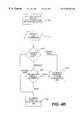
- FIG. 4Ais a flow chart representing the major decision points of a TDR according to a preferred embodiment of the present invention.
- FIG. 4Bis a flow chart representing the major decision points in a programming module.
- FIG. 5is a schematic of a TDR according to a preferred embodiment of the present invention.
- FIG. 6is a schematic of a preferred embodiment of the present invention for one or more originator telephone devices.
- FIG. 3illustrates a preferred embodiment of the present invention.
- a telephone device 150initiates and conducts a communications session with a similar telephone device 160 .
- the telephone device 150is also referred to herein as an originator telephone device 150 .
- the telephone device 160is also referred to herein as a receiver telephone device 160 .
- Telephone devices 150 and 160can be any telephone devices, including telephones, fax machines, and video workstations.
- a PBX 401provides normal telephony-bound connections for the communication session.
- the PBX 401routes a call originated by the telephone device 150 to a PSTN POP 201 .
- the PSTN POP 201is typically located at a phone company “Central Office” or C/O.
- a PSTN 200finds a PSTN POP 202 which provides a direct connection to the telephone device 160 .
- the PSTN 200finds the appropriate PSTN POP 202 , the communication session is established.
- the present inventionis not limited to PBX-based systems. Any telephone switching system can be used.
- a Centrex systemcan be used in place of PBX 401 .
- the switching systemis not limited to be co-located on the customer premises.
- the PBX 401is connected (logically or physically) to a telephony-to-data re-routing system (TDR) 402 .
- TDRtelephony-to-data re-routing system
- the PBX 401is programmed to route specific calls, or all calls generated by specific telephony devices, to the TDR 402 rather than to the PSTN POP 201 .
- the TDR 402preferably responds to calls routed to it in the same manner as the PSTN POP 201 , at least until such time as the connection through a WAN 300 can be established. So, for example, when using a PBX, users must typically enter an “escape digit” (e.g., dial “9” to get an outside line) to connect to the PSTN 200 . At this point, the PSTN POP 201 provides dial-tone to the user, and additional digits are subsequently entered. In the present invention, when the user enters the escape digit, the TDR 402 provides a dial-tone to inform the user that he or she can enter additional digits.
- an “escape digit”e.g., dial “9” to get an outside line
- the PBX 401can be configured to re-route calls based on the phone number entered, or based on a particular telephony condition. If not, as the additional digits are entered, TDR 402 can make this determination. For this reason, the communication link 403 between the PBX 401 and the TDR 402 is shown to have arrows pointing in both directions.
- the TDR 402determines that a particular phone call should be placed through the PSTN 200 , it re-directs the call back through the PBX 401 to the PSTN POP 201 to provide this re-routing.
- the present inventionencompasses three distinct components: (a) re-configuration of the PBX 401 to route calls through the TDR 402 upon the PBX 401 's determination that a call through the WAN 300 is preferable to routing through the PSTN 200 , (b) performance characteristics allowing the TDR 402 to act as a conversion module between the telephony requirements of an originator telephone device 150 and the data requirements of the WAN POP 301 , and (c) routing rules in the TDR 402 that allow it to act as a supplemental module to PSTN 200 .
- the foregoing disclosuredescribes a system directed to telephony call re-routing for a single call originator.
- the present inventionalso applies to environments where multiple telephone devices are connected to the PSTN 200 through a PBX 401 .
- Such telephony devicesinclude fax machines, telex devices, standard telephones, video conferencing equipment, or any other communication device relying on telephony for transport. Any number of users, using any combination of the above devices, can take advantage of the present invention to re-route calls through the WAN 300 instead of the PSTN 200 .
- the PBX 401is configured such that calls from a plurality of fax machines at the site are routed through the same TDR 402 to the WAN 300 .
- the present inventionallows a system administrator to enable any telephony device to use the TDR 402 . This is accomplished by configuring the PBX 401 to enable another telephony device to access the TDR 402 . Further, the system administrator can configure the TDR 402 to implement the least cost routing algorithm to take advantage of any combination of a data network as described above.
- FIG. 4illustrates a preferred configuration for a PBX 401 that can be used with the present invention.
- This configurationmaintains the interface to telephone devices 151 , 152 , and 153 .
- the telephone devices 151 , 152 , and 153are coupled to a PSTN Connection 491 through a programming module 480 .
- calls originated by users of these three devicesare routed to the nearest PSTN POP 201 to establish a telephony connection to a similar remote telephone device.
- users of these devicespress “9” on a telephone keypad, to signal the programming module 480 to create clear paths 256 , 257 , and 258 , respectively, to the PSTN POP 201 .
- the programming module 480is configured to re-route calls through the WAN 300 .
- paths 251 , 252 , and 253 , respectively,are made to hunt group 490 .
- the hunt group 490provides a surrogate path to the TDR 402 , through a TDR connection 494 .
- the hunt group 490is a series of telephone lines organized in such a way that if the first line is busy, the next line is hunted, and so on until a free line is found. Hunt groups are well known in the art and need not be described further.
- FIG. 4Ais a flow chart representing the major decision points and processes of TDR 402 on handling routing for a telephone call.
- the PBX 401initiates an off-hook event through its Hunt Group 490 , and a request is made for a TDR connection 494 into the TDR.
- TDR 402then assigns the call to one of the inbound ports available on one of the telephone boards 443 through 448 in step 424 .
- the assigned telephone boardplays a dial tone in step 426 , which triggers the call originator telephone device 151 , 142 , or 143 to enter the digits of the call receiver's phone number.
- the dialed digitsare collected by the assigned telephone board 443 - 448 in step 428 .
- Routing rulesstored on the TDR 402 , are applied in step 430 . These rules may reflect varying criteria depending on the phone number dialed and the identity of the call originator telephone device (if known). There are two alternate decision paths that can result from the application of the routing rules. The first decision is to re-route the call back to the PSTN in step 432 . In this case, TDR 402 invokes outbound interface 451 , and a connection is made through TDR connection 493 back into the PBX 401 . The second routing decision is to use the WAN for delivery. In this case, a second decision point is to determine whether the call should be made in real-time or in store-and-forward mode in step 434 .
- This decisionalso rests on varying criteria depending on the identity of the call originator telephone device, and that associated user's desired default delivery mode, and/or, typically, an additional “escape code” entered as part of the phone number dialed (e.g., users are instructed to enter “#” preceding any number that should be delivered real-time).
- real-time delivery modeis selected, an immediate WAN connection 495 is established in step 436 . If not, the message is collected and stored by the inbound interface 442 , and the connection to the call originator telephone device is dropped in step 438 . Then, the message is delivered through WAN connection 495 in store-and-forward mode in step 436 .
- the PBX 401There are various configurations or implementations for the PBX 401 .
- One configuration of the PBXallows the PBX to make an alternate routing decision, that is, route some calls toward the PSTN connection 491 and others toward the TDR connection 494 —depending on the telephone number dialed. For example, local calls may be routed directly to the PSTN 200 , while long distance calls are routed to the WAN 300 .
- More sophisticated configurations of the PBX 401allow the PBX 401 to attempt a call to the PSTN 200 , determine that the call receiver's telephone device 160 is not available (e.g., busy or no answer telephony condition), and only then re-route the call over the WAN 300 .
- paths 256 , 257 , and 258are still maintained in the preferred embodiment of the present invention. There are two primary reasons to maintain these paths.
- call originatorsmay desire to “bypass” WAN routing. That is, the call originator may know that a certain call will, by the rules of the programming module 480 , be re-routed to the WAN 300 , but have a desire that the call instead be routed to the PSTN 200 .
- the programming module 480can be configured so that pressing the digit “8”, for example, routes a call directly toward PSTN connection 491 over paths 256 , 257 , and 258 , thereby bypassing the WAN 300 .
- FIG. 4Bis a flow chart representing the major decision points and processes of programming module 480 .
- the user of call originator telephone device 151 , 152 , or 153attempts to place a phone call, initiating the “off-hook event” recognized by the PBX 401 .
- the PBX 401in step 454 , identifies the call originator and extracts the associated user detail information stored in the PBX 401 's memory.
- the PBX 401assesses the escape code digit used to gain access to the PBX.
- the PBX 401routes the call to PSTN connection 492 in step 458 . If the escape code digit indicates a request for forced delivery through the WAN 300 (e.g., using an alternative digit such as “7”), then the PBX 401 routes the call to Hunt Group 490 in step 460 . If the escape code digit is the “default” digit (e.g., “9”) for this particular call originator, then PBX 401 must re-route the call depending on the value, as provided in the user detail information, used “by default” for this call originator.
- the user default value for this call originatoris determined in step 462 . If the user default value is “PSTN” (i.e., entry of escape code digit “9” means connect via the PSTN 200 for this call originator), then the PBX 401 makes a connection to PSTN POP 201 through PSTN connection 492 in step 458 . If the user default value is “WAN” (i.e., entry of escape code digit “9” means connect via the WAN 300 for this call originator), then the PBX 401 makes a connection to TDR connection 494 through Hunt Group 490 in step 460 .
- PSTNi.e., entry of escape code digit “9” means connect via the PSTN 200 for this call originator
- WANi.e., entry of escape code digit “9” means connect via the WAN 300 for this call originator
- the second reason to maintain paths 256 , 257 and 258 in the preferred embodimentis for call reception.
- Each telephone device 151 , 152 , and 153remains available for incoming calls by maintaining the same paths from PSTN POP 201 to these devices that existed prior to the re-configuration of PBX 401 .
- the present inventiondoes not interfere with these incoming calls.
- Path 261can also be connected to any of the inbound paths 256 , 257 , or 258 for the completion of calls originated on another location of WAN 300 , where telephone device 151 , 152 , or 153 is the intended call receiver. This is described in further detail below.
- FIG. 5shows a preferred implementation of the TDR 402 .
- the TDR 402can be a separate computer unit, such as a standard Intel-based computer or a UNIX-based system, with appropriate storage for maintaining routing rules and, in the case of store-and-forward communications, providing temporary storage of messages.
- the TDR 402can be embedded in PC-based implementations of the PBX 401 .
- Other configurations for the TDR 402 incorporating the concepts of the present inventionare possible and would be within the skill of the those in the art.
- the TDR connection 494 from the PBX 401provides paths to telephone boards 443 through 448 .
- the telephone boards 443 through 448can be analog or digital telephony boards, such as those made by Dialogic and Dianatel, fax boards, such as those made by Brooktrout or GammaLink, or any other telephony or communications protocol equipment corresponding to the type of telephone device 151 , 152 , or 153 originating the call.
- TDR 402 equipmentAn important requirement of the TDR 402 equipment is that at least one of the boards be able to provide a dial-tone so that the call originators continue with digit entry (i.e., continue to dial the phone number or other address identifying the call receiver). This is the second step in maintaining a typical telephony interface for call originators.
- An inbound interface 452is a processor that either (a) determines that a real-time connection is called for; (b) determines that a store-and-forward message communication is called for; or (c) determines that the call should be re-routed back through the PBX 401 to the PSTN 200 .
- the terms “inbound” and “outbound”are used in this section with respect to the TDR, not the message. Thus, when the TDR receives a request, it is “inbound” to the TDR; when it sends a response or makes a request, it is “outbound” from the TDR.
- this inbound interface 452determines that a real-time connection is required, the inbound interface 452 enables a direct path to the WAN 300 through a WAN Connection 495 . If the inbound interface 452 determines that a store-and-forward message communication is required, the inbound interface 452 serves as the end-point for message delivery from telephone devices 151 , 152 , and 153 . If the inbound interface 452 determines that a call should be re-routed back through the PBX 401 to the PSTN 200 , the inbound interface 452 routes the call back through an outbound interface 451 , and through a telephone board 441 or 442 , to the TDR connection 493 .
- the inbound interface 452can use a priori knowledge about the particular originator telephone device initiating a call to provide for optimal use of the WAN 300 . For example, if the originator telephone device 151 is known to be a fax machine, its maximum communication speed will be 14,400 bits per second. Even without considering compression possibilities, the inbound interface 452 can request bandwidth services having sufficient capacity to process data at that data rate. This bandwidth requirement is smaller than a comparable fax call over the PSTN 200 , where a bandwidth of 64,000 bits per second is allocated for any analog call originated by any telephone device, including fax machines. Other bandwidth optimization methods are possible at this point as well.
- the communication bandwidth requirements between page transmissionsare generally lower than the communication bandwidth requirements for transmitting scanned lines representative of the pages themselves.
- the inbound interface 452can request a dynamic allocation of bandwidth over the WAN 300 that changes depending on what component of the data content is being transmitted.
- the inbound interface 452can also include communication content handling, in a real-time or a store-and-forward mode.
- Communication content handling functionsprovide additional value to the call originators and receivers.
- Communication content handling functionsare alternately referred to as value-added services.
- the digitization of the communication content(voice, fax, e-mail message, etc.) allows for two services optimized for data networks.
- the two servicesare compression and security services. Compression represents the content of the communication in the smallest number of bytes without loss of the meaning intended (or with minimal loss, such as with some voice compression techniques).
- Security servicesare typically separated into encryption and authentication components. Encryption renders the digitization in a format that cannot be interpreted by an unauthorized intermediary intercepting the communication. Authentication unequivocally identifies that the call originator is a specific individual, and no other.
- the content handling featurescan be applied at a centralized point in the communications flow, rather than in the telephone device itself.
- Centralized application of the content handling featuresprovides a significant advantage to both the call participants and the PBX administrator.
- the call participantsare not burdened by additional equipment connected to their telephone devices (if not embedded in the device itself), nor by the requirement to maintain their own private information for security services (i.e., “keys” for the control of encryption and authentication).
- the centralized encryption services allowed by the present inventionallow a PBX administrator to control key management, and any updates required to provide compression or security services.
- the TDR 402provides one centralized point in the system where such encryption services can be offered. As described above, therefore, the present invention removes the need for providing such services at the location of each telephone device 151 , 152 , and 153 .
- the preferred embodiment of the present inventionalso allows for incoming calls through the WAN 300 to the telephone devices 151 , 152 , and 153 through the path available through the outbound interface 451 .
- This feature of the preferred embodimentis provided via a telephone board 441 or 442 , and the TDR connection 493 .
- the WAN Connection 495is implemented through typical local or wide-area network connection equipment.
- such equipmentincludes an ethernet network interface card in the TDR 402 and an external router.
- a conversionis made by a device capable of converting the digital communication so as to provide a point-to-point connection between the call originator telephone device and a receiver telephone device 160 .
- the receiver telephone device 160is similar in type (e.g., telephone, fax machine, etc.) to the call originator's telephone device.
- the other devicecan be a PBX equipped with a TDR similar to TDR 402 to accept incoming calls from the WAN 300 .
- a telephone device 160is not available for call reception.
- the telephone device 160can be busy or does not answer.
- the TDR 402can serve as a surrogate call receiver.
- the TDR 402can serve as a voice message forwarding service for the call originator for an intended telephone conversation.
- the TDR 402can serve as a voice mail service for the call receiver.
- the TDR 402can also perform store-and-forward functionality under explicit instruction from the call originator or the call receiver, or both. That is, the call originator can originate the call with the desire that the TDR 402 will store-and-forward the message. One reason a call originator may desire such storing and forwarding of messages is to benefit from a lower cost for transmittal of the message at a later time. Also, the call receiver can configure the TDR 402 to act as its message receipt intermediary for all calls, such as with e-mail messages.
- the flexibility offered by the store-and-forward functionality of the present inventioncan be expanded by combining it with the content handling capabilities described above.
- the combinationallows the TDR 402 to commission store-and-forward functionality for a specific communication or for all communication meeting one or more criteria.
- the TDR 402can be instructed to send all messages to a particular user at a particular time.
- the call originating telephone devices 151 , 152 , and/or 153send instructions to the TDR 402 .
- a system operatorsends instructions to the TDR 402 .
- a receiver telephone devicee.g., fax 103
- the receiver telephone devicecan instruct the TDR 402 to store all calls destined for the receiver device for handling at a later time.
- the store-and-forward functionality of the present inventionapplies to both video data as well as voice data.
- video datacan be streamed for real-time transmission, or staged for transmission at a later time.
- FIG. 6illustrates a preferred embodiment of a complete system which incorporates a preferred embodiment of the present invention at the point of origination.
- the telephone devices 151 , 152 , and 153are positioned in the same relationship to PBX 401 as in conventional systems.
- the PBX 401has, though, been re-configured, as described above, to route call origination to the TDR 402 instead of to the PSTN 201 POP.
- the TDR 402thus acts as a conversion device, taking telephone-based call origination and providing data network-based call traffic to call receivers.
- the TDR 402can alternatively re-route calls through the PSTN POP 201 .
- FIG. 6also identifies an additional task that can be carried out by the present invention.
- This additional taskis the identification of the call originator, to properly track system usage.
- the PBX 401In the worst case, that is, where no additional identification of the call originator is passed to the TDR 402 , the PBX 401 must keep track of each call origination separately. In this case, a later correlation of time stamps on the PBX 401 and the TDR 402 can be used to connect call origination (the device or user originating the call) to call details kept by the TDR 402 .
- the call originatorcan be identified.
- the call originating fax machineidentifies itself with a terminal station identifier (TSI).
- TSIterminal station identifier
- at least one telephone board 443 - 448should be capable of fax communications, and of recording or at least forwarding the TSI value to the TDR 402 .
- each of the telephone devices 151 , 152 , and 153has unique TSI values set. If they do not, they can either be re-programmed so as to make them unique, or the correlation procedure can be used to identify the proper call originator where the TSI duplication makes this identification ambiguous.
- Charges for the use of the PSTN 200are generally variable and time based. That is, the PSTN 200 charges can change over time and are usually assessed for the time of use.
- the WAN 300 chargesare generally assessed either on a per character transmitted basis, or on a bandwidth required basis.
Landscapes
- Engineering & Computer Science (AREA)
- Signal Processing (AREA)
- Computer Networks & Wireless Communication (AREA)
- General Engineering & Computer Science (AREA)
- Telephonic Communication Services (AREA)
- Data Exchanges In Wide-Area Networks (AREA)
Abstract
Description
Claims (72)
Priority Applications (1)
| Application Number | Priority Date | Filing Date | Title |
|---|---|---|---|
| US08/936,830US6307853B1 (en) | 1996-11-21 | 1997-09-25 | Re-routing telephony communications traffic through a private branch exchange to a data network |
Applications Claiming Priority (2)
| Application Number | Priority Date | Filing Date | Title |
|---|---|---|---|
| US3144796P | 1996-11-21 | 1996-11-21 | |
| US08/936,830US6307853B1 (en) | 1996-11-21 | 1997-09-25 | Re-routing telephony communications traffic through a private branch exchange to a data network |
Publications (1)
| Publication Number | Publication Date |
|---|---|
| US6307853B1true US6307853B1 (en) | 2001-10-23 |
Family
ID=26707262
Family Applications (1)
| Application Number | Title | Priority Date | Filing Date |
|---|---|---|---|
| US08/936,830Expired - LifetimeUS6307853B1 (en) | 1996-11-21 | 1997-09-25 | Re-routing telephony communications traffic through a private branch exchange to a data network |
Country Status (1)
| Country | Link |
|---|---|
| US (1) | US6307853B1 (en) |
Cited By (35)
| Publication number | Priority date | Publication date | Assignee | Title |
|---|---|---|---|---|
| US20020001378A1 (en)* | 2000-06-30 | 2002-01-03 | Yoshikatsu Ooi | Communication apparatus |
| US20020057672A1 (en)* | 1997-10-16 | 2002-05-16 | Toshinao Komuro | Internet telephone system |
| WO2002078278A1 (en)* | 2001-03-20 | 2002-10-03 | Motorola, Inc., A Corporation Of The State Of Delaware | Optimizing voice-over-ip priority and bandwidth requirements |
| US6519251B1 (en)* | 1998-06-08 | 2003-02-11 | Samsung Electronics Co., Ltd. | Apparatus and method for interconnecting private exchange system to the internet |
| WO2002041571A3 (en)* | 2000-11-16 | 2003-05-22 | C D C S R L | Apparatus and method for integrating voice and data transmission on lans and automatic least cost routing |
| US6577621B1 (en)* | 1999-06-22 | 2003-06-10 | Ericsson Inc. | System and method for providing high-speed local telecommunications access |
| US20030214940A1 (en)* | 2002-05-16 | 2003-11-20 | Takken Todd E. | Internet telephony system for enabling internet telephone access from traditional telephone interface |
| US6728238B1 (en)* | 1998-05-06 | 2004-04-27 | Remote Switch Systems, Inc. | Dynamic allocation of voice and data channels in a time division multiplexed telecommunications system |
| WO2004023723A3 (en)* | 2002-09-09 | 2004-05-21 | Superclick Networks Inc | Diverting data call from a telephone network through a private branch exchange to a data network |
| US6763102B1 (en)* | 2001-04-05 | 2004-07-13 | At&T Corp. | Method for handling incoming calls directed to a virtual communication service subscriber via a guest PBX |
| US6785263B1 (en)* | 1999-01-20 | 2004-08-31 | Fujitsu Limited | Communication control method in complex switched network and gateway using the method |
| US20040205777A1 (en)* | 2002-07-05 | 2004-10-14 | Anthony Zalenski | System and method for using multiple communication protocols in memory limited processors |
| US20040234064A1 (en)* | 2003-05-19 | 2004-11-25 | John Melideo | Telephone call initiation through an on-line search |
| WO2004102941A1 (en)* | 2003-03-21 | 2004-11-25 | Easylink Networks Inc. | System and process for routing telephony communications from a conventional telephone set through a data network |
| US20040258048A1 (en)* | 2003-05-19 | 2004-12-23 | John Melideo | Application independent telephone call initiation |
| US20050002379A1 (en)* | 2003-05-22 | 2005-01-06 | Bye Richard A. | Dynamic real-time quality management of packetized communications in a network environment |
| US20050025134A1 (en)* | 1999-05-03 | 2005-02-03 | Cisco Technology, Inc. | Packet-switched telephony with circuit-switched backup |
| US20050078690A1 (en)* | 2003-10-14 | 2005-04-14 | Delangis Eric M. | Residential communications gateway (RCG) for broadband communications over a plurality of standard POTS lines, with dynamic allocation of said bandwidth, that requires no additional equipment or modifications to the associated class 5 offices or the PSTN at large |
| US6882640B1 (en)* | 2000-09-22 | 2005-04-19 | Siemens Communications, Inc. | System and method for utilizing circuit switched and packet switched resources |
| US6944151B1 (en)* | 1997-09-16 | 2005-09-13 | Mediatrix Telecom, Inc. | Apparatus and method to use a conventional telephone set to make telephone calls on a packet network |
| US20050201414A1 (en)* | 2004-03-11 | 2005-09-15 | Ali Awais | Dynamically adapting the transmission rate of packets in real-time VoIP communications to the available bandwidth |
| US20060031393A1 (en)* | 2004-01-28 | 2006-02-09 | Cooney John M | System and method of binding a client to a server |
| US20060034296A1 (en)* | 2004-08-16 | 2006-02-16 | I2 Telecom International, Inc. | System and method for sharing an IP address |
| US7019853B1 (en)* | 1998-04-10 | 2006-03-28 | Canon Kabushiki Kaisha | Image communication apparatus and method |
| EP1770967A1 (en)* | 2005-10-03 | 2007-04-04 | Lagunawave, Inc. | VOIP with local call access |
| US20070133396A1 (en)* | 1998-08-03 | 2007-06-14 | Siemens Aktiengesellschaft | Method for re-routing data packets onto an alternative network |
| US20070248081A1 (en)* | 2004-10-20 | 2007-10-25 | I2Telecom International, Inc. | Portable VoIP Service Access Module |
| US20080013702A1 (en)* | 2003-05-19 | 2008-01-17 | John Melideo | Telephone Call Initiation Through An On-Line Search |
| US20090097478A1 (en)* | 2007-10-10 | 2009-04-16 | Microsoft Corporation | Techniques to access messaging services for branch offices |
| US20090156222A1 (en)* | 2007-12-17 | 2009-06-18 | I2Telecom International, Inc. | Systems and methods of making a call |
| US7606217B2 (en)* | 2003-07-02 | 2009-10-20 | I2 Telecom International, Inc. | System and method for routing telephone calls over a voice and data network |
| US20120195303A1 (en)* | 2011-01-31 | 2012-08-02 | Avaya Inc. | System and method for integrating conventional enterprise communication systems into an ip multimedia subsystem-based services environment |
| US20130215457A1 (en)* | 2012-02-16 | 2013-08-22 | Fuji Xerox Co., Ltd. | Communication apparatus, communication control apparatus, communication system, and communication method |
| US8804758B2 (en) | 2004-03-11 | 2014-08-12 | Hipcricket, Inc. | System and method of media over an internet protocol communication |
| JP2019208163A (en)* | 2018-05-30 | 2019-12-05 | 日本電信電話株式会社 | Communication method, communication system, authentication device, and user terminal |
Citations (13)
| Publication number | Priority date | Publication date | Assignee | Title |
|---|---|---|---|---|
| US5341374A (en)* | 1991-03-01 | 1994-08-23 | Trilan Systems Corporation | Communication network integrating voice data and video with distributed call processing |
| US5369686A (en)* | 1993-02-12 | 1994-11-29 | Open Port Technology, Inc. | Method and apparatus for secondary-option message delivery through enhanced service message handlers |
| US5519770A (en)* | 1990-06-26 | 1996-05-21 | Australian And Overseas Telecommunications Corporation Limited | Enhanced telephony apparatus and system |
| US5521910A (en)* | 1994-01-28 | 1996-05-28 | Cabletron Systems, Inc. | Method for determining a best path between two nodes |
| US5673299A (en)* | 1984-09-14 | 1997-09-30 | Accessline Technologies, Inc. | Adjunct controller for a telephone system |
| US5712907A (en)* | 1995-09-18 | 1998-01-27 | Open Port Technology, Inc. | Pro-active message delivery system and method |
| US5726984A (en)* | 1989-01-31 | 1998-03-10 | Norand Corporation | Hierarchical data collection network supporting packetized voice communications among wireless terminals and telephones |
| US5742596A (en)* | 1995-11-12 | 1998-04-21 | Phonet Communication Ltd. | Network based distributed PBX system |
| US5751706A (en)* | 1996-06-05 | 1998-05-12 | Cignal Global Communications, Inc. | System and method for establishing a call telecommunications path |
| US5761417A (en)* | 1994-09-08 | 1998-06-02 | International Business Machines Corporation | Video data streamer having scheduler for scheduling read request for individual data buffers associated with output ports of communication node to one storage node |
| US5764741A (en)* | 1995-07-21 | 1998-06-09 | Callmanage Ltd. | Least cost rooting system |
| US5926535A (en)* | 1996-08-05 | 1999-07-20 | International Business Machines Corporation | Third party call control |
| US5940479A (en)* | 1996-10-01 | 1999-08-17 | Northern Telecom Limited | System and method for transmitting aural information between a computer and telephone equipment |
- 1997
- 1997-09-25USUS08/936,830patent/US6307853B1/ennot_activeExpired - Lifetime
Patent Citations (13)
| Publication number | Priority date | Publication date | Assignee | Title |
|---|---|---|---|---|
| US5673299A (en)* | 1984-09-14 | 1997-09-30 | Accessline Technologies, Inc. | Adjunct controller for a telephone system |
| US5726984A (en)* | 1989-01-31 | 1998-03-10 | Norand Corporation | Hierarchical data collection network supporting packetized voice communications among wireless terminals and telephones |
| US5519770A (en)* | 1990-06-26 | 1996-05-21 | Australian And Overseas Telecommunications Corporation Limited | Enhanced telephony apparatus and system |
| US5341374A (en)* | 1991-03-01 | 1994-08-23 | Trilan Systems Corporation | Communication network integrating voice data and video with distributed call processing |
| US5369686A (en)* | 1993-02-12 | 1994-11-29 | Open Port Technology, Inc. | Method and apparatus for secondary-option message delivery through enhanced service message handlers |
| US5521910A (en)* | 1994-01-28 | 1996-05-28 | Cabletron Systems, Inc. | Method for determining a best path between two nodes |
| US5761417A (en)* | 1994-09-08 | 1998-06-02 | International Business Machines Corporation | Video data streamer having scheduler for scheduling read request for individual data buffers associated with output ports of communication node to one storage node |
| US5764741A (en)* | 1995-07-21 | 1998-06-09 | Callmanage Ltd. | Least cost rooting system |
| US5712907A (en)* | 1995-09-18 | 1998-01-27 | Open Port Technology, Inc. | Pro-active message delivery system and method |
| US5742596A (en)* | 1995-11-12 | 1998-04-21 | Phonet Communication Ltd. | Network based distributed PBX system |
| US5751706A (en)* | 1996-06-05 | 1998-05-12 | Cignal Global Communications, Inc. | System and method for establishing a call telecommunications path |
| US5926535A (en)* | 1996-08-05 | 1999-07-20 | International Business Machines Corporation | Third party call control |
| US5940479A (en)* | 1996-10-01 | 1999-08-17 | Northern Telecom Limited | System and method for transmitting aural information between a computer and telephone equipment |
Cited By (70)
| Publication number | Priority date | Publication date | Assignee | Title |
|---|---|---|---|---|
| US6944151B1 (en)* | 1997-09-16 | 2005-09-13 | Mediatrix Telecom, Inc. | Apparatus and method to use a conventional telephone set to make telephone calls on a packet network |
| US20020057672A1 (en)* | 1997-10-16 | 2002-05-16 | Toshinao Komuro | Internet telephone system |
| US6819663B2 (en)* | 1997-10-16 | 2004-11-16 | Fujitsu Limited | Internet telephone system |
| US7019853B1 (en)* | 1998-04-10 | 2006-03-28 | Canon Kabushiki Kaisha | Image communication apparatus and method |
| US7453606B2 (en) | 1998-04-10 | 2008-11-18 | Canon Kabushiki Kaisha | Image communication apparatus and method |
| US6728238B1 (en)* | 1998-05-06 | 2004-04-27 | Remote Switch Systems, Inc. | Dynamic allocation of voice and data channels in a time division multiplexed telecommunications system |
| US6519251B1 (en)* | 1998-06-08 | 2003-02-11 | Samsung Electronics Co., Ltd. | Apparatus and method for interconnecting private exchange system to the internet |
| US20070133396A1 (en)* | 1998-08-03 | 2007-06-14 | Siemens Aktiengesellschaft | Method for re-routing data packets onto an alternative network |
| US7239631B1 (en)* | 1998-08-03 | 2007-07-03 | Siemens Aktiengesellschaft | Method for re-routing data packets onto an alternative network |
| US6785263B1 (en)* | 1999-01-20 | 2004-08-31 | Fujitsu Limited | Communication control method in complex switched network and gateway using the method |
| US20050025134A1 (en)* | 1999-05-03 | 2005-02-03 | Cisco Technology, Inc. | Packet-switched telephony with circuit-switched backup |
| US7668158B2 (en)* | 1999-05-03 | 2010-02-23 | Cisco Technology, Inc. | Packet-switched telephony with circuit-switched backup |
| US6577621B1 (en)* | 1999-06-22 | 2003-06-10 | Ericsson Inc. | System and method for providing high-speed local telecommunications access |
| US20020001378A1 (en)* | 2000-06-30 | 2002-01-03 | Yoshikatsu Ooi | Communication apparatus |
| US7912038B2 (en) | 2000-09-22 | 2011-03-22 | Berger H Stephen | System and method for utilizing circuit switched and packet switched resources |
| US20060023696A1 (en)* | 2000-09-22 | 2006-02-02 | Siemens Information And Communications Products, Inc. | System and method for utilizing circuit switched and packet switched resources |
| US6882640B1 (en)* | 2000-09-22 | 2005-04-19 | Siemens Communications, Inc. | System and method for utilizing circuit switched and packet switched resources |
| US20040023687A1 (en)* | 2000-11-16 | 2004-02-05 | Giuseppe Diomelli | Apparatus and method for integrating phone communications and data transmission on lans and for automatically selecting lowest-prices carrier and connection mode |
| WO2002041571A3 (en)* | 2000-11-16 | 2003-05-22 | C D C S R L | Apparatus and method for integrating voice and data transmission on lans and automatic least cost routing |
| US7239689B2 (en) | 2000-11-16 | 2007-07-03 | C.D.C. S.R.L. | Apparatus and method for integrating phone communications and data transmission on LANs and for automatically selecting lowest-prices carrier and connection mode |
| CN100358316C (en)* | 2000-11-16 | 2007-12-26 | C·D·C·公司 | A device and method |
| WO2002078278A1 (en)* | 2001-03-20 | 2002-10-03 | Motorola, Inc., A Corporation Of The State Of Delaware | Optimizing voice-over-ip priority and bandwidth requirements |
| US6763102B1 (en)* | 2001-04-05 | 2004-07-13 | At&T Corp. | Method for handling incoming calls directed to a virtual communication service subscriber via a guest PBX |
| US7961865B1 (en) | 2001-04-05 | 2011-06-14 | AT&T Intellectual Property II, L.P | Method for handling incoming calls directed to a virtual communication service subscriber via a guest PBX |
| US8295270B2 (en)* | 2002-05-16 | 2012-10-23 | International Business Machines Corporation | Internet telephony system for enabling internet telephone access from traditional telephone interface |
| US20030214940A1 (en)* | 2002-05-16 | 2003-11-20 | Takken Todd E. | Internet telephony system for enabling internet telephone access from traditional telephone interface |
| US9112953B2 (en) | 2002-05-16 | 2015-08-18 | International Business Machines Corporation | Internet telephony unit and software for enabling internet telephone access from traditional telephone interface |
| US20040205777A1 (en)* | 2002-07-05 | 2004-10-14 | Anthony Zalenski | System and method for using multiple communication protocols in memory limited processors |
| US7957401B2 (en) | 2002-07-05 | 2011-06-07 | Geos Communications, Inc. | System and method for using multiple communication protocols in memory limited processors |
| WO2004023723A3 (en)* | 2002-09-09 | 2004-05-21 | Superclick Networks Inc | Diverting data call from a telephone network through a private branch exchange to a data network |
| WO2004102941A1 (en)* | 2003-03-21 | 2004-11-25 | Easylink Networks Inc. | System and process for routing telephony communications from a conventional telephone set through a data network |
| US20040258048A1 (en)* | 2003-05-19 | 2004-12-23 | John Melideo | Application independent telephone call initiation |
| US20060182250A1 (en)* | 2003-05-19 | 2006-08-17 | John Melideo | Application Independent Call Initiation |
| US20040234064A1 (en)* | 2003-05-19 | 2004-11-25 | John Melideo | Telephone call initiation through an on-line search |
| US7240290B2 (en) | 2003-05-19 | 2007-07-03 | John Melideo | Telephone call initiation through an on-line search |
| US7496858B2 (en) | 2003-05-19 | 2009-02-24 | Jambo Acquisition, Llc | Telephone call initiation through an on-line search |
| US7103010B2 (en) | 2003-05-19 | 2006-09-05 | Jambotech, Llc | Application independent telephone call initiation |
| US20080013702A1 (en)* | 2003-05-19 | 2008-01-17 | John Melideo | Telephone Call Initiation Through An On-Line Search |
| US7664036B2 (en)* | 2003-05-22 | 2010-02-16 | Broadcom Corporation | Dynamic real-time quality management of packetized communications in a network environment |
| US20050002379A1 (en)* | 2003-05-22 | 2005-01-06 | Bye Richard A. | Dynamic real-time quality management of packetized communications in a network environment |
| US7606217B2 (en)* | 2003-07-02 | 2009-10-20 | I2 Telecom International, Inc. | System and method for routing telephone calls over a voice and data network |
| US7606156B2 (en)* | 2003-10-14 | 2009-10-20 | Delangis Eric M | Residential communications gateway (RCG) for broadband communications over a plurality of standard POTS lines, with dynamic allocation of said bandwidth, that requires no additional equipment or modifications to the associated class 5 offices or the PSTN at large |
| US20050078690A1 (en)* | 2003-10-14 | 2005-04-14 | Delangis Eric M. | Residential communications gateway (RCG) for broadband communications over a plurality of standard POTS lines, with dynamic allocation of said bandwidth, that requires no additional equipment or modifications to the associated class 5 offices or the PSTN at large |
| US7676599B2 (en) | 2004-01-28 | 2010-03-09 | I2 Telecom Ip Holdings, Inc. | System and method of binding a client to a server |
| US20060031393A1 (en)* | 2004-01-28 | 2006-02-09 | Cooney John M | System and method of binding a client to a server |
| US20090067341A1 (en)* | 2004-03-11 | 2009-03-12 | I2Telecom International, Inc. | System and method of voice over internet protocol communication |
| US8335232B2 (en) | 2004-03-11 | 2012-12-18 | Geos Communications IP Holdings, Inc., a wholly owned subsidiary of Augme Technologies, Inc. | Method and system of renegotiating end-to-end voice over internet protocol CODECs |
| US8804758B2 (en) | 2004-03-11 | 2014-08-12 | Hipcricket, Inc. | System and method of media over an internet protocol communication |
| US20050201414A1 (en)* | 2004-03-11 | 2005-09-15 | Ali Awais | Dynamically adapting the transmission rate of packets in real-time VoIP communications to the available bandwidth |
| US7460480B2 (en) | 2004-03-11 | 2008-12-02 | I2Telecom International, Inc. | Dynamically adapting the transmission rate of packets in real-time VoIP communications to the available bandwidth |
| US8842568B2 (en) | 2004-03-11 | 2014-09-23 | Hipcricket, Inc. | Method and system of renegotiating end-to-end voice over internet protocol CODECs |
| US20100238834A9 (en)* | 2004-03-11 | 2010-09-23 | I2Telecom International, Inc. | System and method of voice over internet protocol communication |
| US7782878B2 (en) | 2004-08-16 | 2010-08-24 | I2Telecom Ip Holdings, Inc. | System and method for sharing an IP address |
| US20060034296A1 (en)* | 2004-08-16 | 2006-02-16 | I2 Telecom International, Inc. | System and method for sharing an IP address |
| US20080025291A1 (en)* | 2004-10-20 | 2008-01-31 | I2 Telecom International, Inc. | Portable VoIP Service Access Module |
| US20070248081A1 (en)* | 2004-10-20 | 2007-10-25 | I2Telecom International, Inc. | Portable VoIP Service Access Module |
| EP1770967A1 (en)* | 2005-10-03 | 2007-04-04 | Lagunawave, Inc. | VOIP with local call access |
| US20070121592A1 (en)* | 2005-10-03 | 2007-05-31 | Sean Ryan | VOIP With Local Call Access |
| US10057411B2 (en) | 2007-10-10 | 2018-08-21 | Microsoft Technology Licensing, Llc | Techniques to access messaging services for branch offices |
| US20090097478A1 (en)* | 2007-10-10 | 2009-04-16 | Microsoft Corporation | Techniques to access messaging services for branch offices |
| US9049051B2 (en) | 2007-10-10 | 2015-06-02 | Microsoft Technology Licensing, Llc | Techniques to access messaging services for branch offices |
| US8504048B2 (en) | 2007-12-17 | 2013-08-06 | Geos Communications IP Holdings, Inc., a wholly owned subsidiary of Augme Technologies, Inc. | Systems and methods of making a call |
| US20090156222A1 (en)* | 2007-12-17 | 2009-06-18 | I2Telecom International, Inc. | Systems and methods of making a call |
| US9276965B2 (en) | 2007-12-17 | 2016-03-01 | Hipcricket, Inc. | Systems and methods of making a call |
| US20120195303A1 (en)* | 2011-01-31 | 2012-08-02 | Avaya Inc. | System and method for integrating conventional enterprise communication systems into an ip multimedia subsystem-based services environment |
| US8917720B2 (en)* | 2011-01-31 | 2014-12-23 | Avaya Inc. | System and method for integrating conventional enterprise communication systems into an IP multimedia subsystem-based services environment |
| US9282204B2 (en)* | 2012-02-16 | 2016-03-08 | Fuji Xerox Co., Ltd. | Communication apparatus, communication control apparatus, communication system, and communication method |
| US20130215457A1 (en)* | 2012-02-16 | 2013-08-22 | Fuji Xerox Co., Ltd. | Communication apparatus, communication control apparatus, communication system, and communication method |
| JP2019208163A (en)* | 2018-05-30 | 2019-12-05 | 日本電信電話株式会社 | Communication method, communication system, authentication device, and user terminal |
| WO2019230446A1 (en)* | 2018-05-30 | 2019-12-05 | 日本電信電話株式会社 | Communication method, communication system, authentication device and user terminal |
Similar Documents
| Publication | Publication Date | Title |
|---|---|---|
| US6307853B1 (en) | Re-routing telephony communications traffic through a private branch exchange to a data network | |
| US7596129B2 (en) | Home gateway systems and methods to establish communication sessions | |
| US6546003B1 (en) | Telecommunications system | |
| US7889722B2 (en) | System for interconnecting standard telephony communications equipment to internet protocol networks | |
| US6292479B1 (en) | Transport of caller identification information through diverse communication networks | |
| US6463051B1 (en) | Internet calling system | |
| US5625677A (en) | Simultaneous voice and data communications | |
| US6697357B2 (en) | Call management messaging system for integrating the internet with the public switched telephone network | |
| JP3940122B2 (en) | Method for forming usable features for alternate connections of primary connections | |
| US6069890A (en) | Internet telephone service | |
| US6128293A (en) | Multiservice access management system | |
| EP0905959A2 (en) | A packet-switched-network telephone system | |
| US20050180397A1 (en) | Call processing system and method in a voice and data integrated switching system | |
| US20040008670A1 (en) | System for interconnecting packet-switched and circuit-switched voice communications | |
| US6870905B2 (en) | Wiretap implemented by media gateway multicasting | |
| WO1997028628A9 (en) | Hybrid network for real-time phone-to-phone voice communications | |
| WO1997028628A1 (en) | Hybrid network for real-time phone-to-phone voice communications | |
| US6438218B1 (en) | Internet telephone service | |
| US8995434B2 (en) | System for interconnecting standard telephony communications equipment to internet | |
| EP0969689A1 (en) | Switching internet traffic through digital switches having a time slot interchange network | |
| EP0969689A2 (en) | Switching internet traffic through digital switches having a time slot interchange network | |
| US8565224B2 (en) | Telephone system, telephone exchange apparatus, and connection control method used in telephone exchange apparatus | |
| US20090285373A1 (en) | Method for using digital data networks for the transmission of data via voice connection paths | |
| US7436851B1 (en) | Destination call routing apparatus and method | |
| US6407995B1 (en) | Independently switched voice and data calls using a single PSTN line connection |
Legal Events
| Date | Code | Title | Description |
|---|---|---|---|
| AS | Assignment | Owner name:OPEN PORT TECHNOLOGY, INC., ILLINOIS Free format text:ASSIGNMENT OF ASSIGNORS INTEREST;ASSIGNORS:STORCH, RANDY S.;NANDYAL, OMPRASAD S.;DUTRA, ANTONIO;AND OTHERS;REEL/FRAME:008787/0248;SIGNING DATES FROM 19970826 TO 19970828 | |
| AS | Assignment | Owner name:SILICON VALLEY BANK, CALIFORNIA Free format text:SECURITY AGREEMENT;ASSIGNOR:OPEN PORT TECHNOLOGY, INC.;REEL/FRAME:009139/0652 Effective date:19980323 | |
| AS | Assignment | Owner name:CID MEZZANINE CAPITAL, L.P., INDIANA Free format text:SECURITY INTEREST;ASSIGNOR:OPEN PORT TECHNOLOGY, INC.;REEL/FRAME:009670/0883 Effective date:19980619 | |
| AS | Assignment | Owner name:SILICON VALLEY BANK, CALIFORNIA Free format text:RELEASE;ASSIGNOR:OPEN PORT TECHNOLOGY, INC.;REEL/FRAME:010478/0814 Effective date:19980323 | |
| AS | Assignment | Owner name:OPEN PORT TECHNOLOGY, INC., ILLINOIS Free format text:RELEASE OF SECURITY AGREEMENT;ASSIGNOR:SILICON VALLEY BANK;REEL/FRAME:010731/0799 Effective date:20000404 | |
| AS | Assignment | Owner name:NET2PHONE, INC., NEW JERSEY Free format text:ASSIGNMENT OF ASSIGNORS INTEREST;ASSIGNOR:OPEN PORT TECHNOLOGY, INC.;REEL/FRAME:011590/0917 Effective date:20010206 | |
| STCF | Information on status: patent grant | Free format text:PATENTED CASE | |
| FEPP | Fee payment procedure | Free format text:PAT HOLDER CLAIMS SMALL ENTITY STATUS, ENTITY STATUS SET TO SMALL (ORIGINAL EVENT CODE: LTOS); ENTITY STATUS OF PATENT OWNER: SMALL ENTITY | |
| REFU | Refund | Free format text:REFUND - PAYMENT OF MAINTENANCE FEE, 4TH YEAR, LARGE ENTITY (ORIGINAL EVENT CODE: R1551); ENTITY STATUS OF PATENT OWNER: SMALL ENTITY | |
| FPAY | Fee payment | Year of fee payment:4 | |
| FEPP | Fee payment procedure | Free format text:PAYER NUMBER DE-ASSIGNED (ORIGINAL EVENT CODE: RMPN); ENTITY STATUS OF PATENT OWNER: SMALL ENTITY Free format text:PAYOR NUMBER ASSIGNED (ORIGINAL EVENT CODE: ASPN); ENTITY STATUS OF PATENT OWNER: SMALL ENTITY | |
| FPAY | Fee payment | Year of fee payment:8 | |
| SULP | Surcharge for late payment | Year of fee payment:7 | |
| FEPP | Fee payment procedure | Free format text:PAYER NUMBER DE-ASSIGNED (ORIGINAL EVENT CODE: RMPN); ENTITY STATUS OF PATENT OWNER: SMALL ENTITY Free format text:PAYOR NUMBER ASSIGNED (ORIGINAL EVENT CODE: ASPN); ENTITY STATUS OF PATENT OWNER: SMALL ENTITY | |
| FPAY | Fee payment | Year of fee payment:12 |