US6307688B1 - Optical system, in particular projection-illumination unit used in microlithography - Google Patents
Optical system, in particular projection-illumination unit used in microlithographyDownload PDFInfo
- Publication number
- US6307688B1 US6307688B1US09/444,815US44481599AUS6307688B1US 6307688 B1US6307688 B1US 6307688B1US 44481599 AUS44481599 AUS 44481599AUS 6307688 B1US6307688 B1US 6307688B1
- Authority
- US
- United States
- Prior art keywords
- inner ring
- optical system
- lever
- mount
- tensile
- Prior art date
- Legal status (The legal status is an assumption and is not a legal conclusion. Google has not performed a legal analysis and makes no representation as to the accuracy of the status listed.)
- Expired - Lifetime
Links
Images

Classifications
- G—PHYSICS
- G03—PHOTOGRAPHY; CINEMATOGRAPHY; ANALOGOUS TECHNIQUES USING WAVES OTHER THAN OPTICAL WAVES; ELECTROGRAPHY; HOLOGRAPHY
- G03F—PHOTOMECHANICAL PRODUCTION OF TEXTURED OR PATTERNED SURFACES, e.g. FOR PRINTING, FOR PROCESSING OF SEMICONDUCTOR DEVICES; MATERIALS THEREFOR; ORIGINALS THEREFOR; APPARATUS SPECIALLY ADAPTED THEREFOR
- G03F7/00—Photomechanical, e.g. photolithographic, production of textured or patterned surfaces, e.g. printing surfaces; Materials therefor, e.g. comprising photoresists; Apparatus specially adapted therefor
- G03F7/20—Exposure; Apparatus therefor
- G—PHYSICS
- G03—PHOTOGRAPHY; CINEMATOGRAPHY; ANALOGOUS TECHNIQUES USING WAVES OTHER THAN OPTICAL WAVES; ELECTROGRAPHY; HOLOGRAPHY
- G03F—PHOTOMECHANICAL PRODUCTION OF TEXTURED OR PATTERNED SURFACES, e.g. FOR PRINTING, FOR PROCESSING OF SEMICONDUCTOR DEVICES; MATERIALS THEREFOR; ORIGINALS THEREFOR; APPARATUS SPECIALLY ADAPTED THEREFOR
- G03F7/00—Photomechanical, e.g. photolithographic, production of textured or patterned surfaces, e.g. printing surfaces; Materials therefor, e.g. comprising photoresists; Apparatus specially adapted therefor
- G03F7/70—Microphotolithographic exposure; Apparatus therefor
- G03F7/708—Construction of apparatus, e.g. environment aspects, hygiene aspects or materials
- G03F7/70908—Hygiene, e.g. preventing apparatus pollution, mitigating effect of pollution or removing pollutants from apparatus
- G03F7/70941—Stray fields and charges, e.g. stray light, scattered light, flare, transmission loss
- G—PHYSICS
- G02—OPTICS
- G02B—OPTICAL ELEMENTS, SYSTEMS OR APPARATUS
- G02B7/00—Mountings, adjusting means, or light-tight connections, for optical elements
- G02B7/008—Mountings, adjusting means, or light-tight connections, for optical elements with means for compensating for changes in temperature or for controlling the temperature; thermal stabilisation
- G—PHYSICS
- G02—OPTICS
- G02B—OPTICAL ELEMENTS, SYSTEMS OR APPARATUS
- G02B7/00—Mountings, adjusting means, or light-tight connections, for optical elements
- G02B7/02—Mountings, adjusting means, or light-tight connections, for optical elements for lenses
- G02B7/023—Mountings, adjusting means, or light-tight connections, for optical elements for lenses permitting adjustment
- G—PHYSICS
- G02—OPTICS
- G02B—OPTICAL ELEMENTS, SYSTEMS OR APPARATUS
- G02B7/00—Mountings, adjusting means, or light-tight connections, for optical elements
- G02B7/02—Mountings, adjusting means, or light-tight connections, for optical elements for lenses
- G02B7/028—Mountings, adjusting means, or light-tight connections, for optical elements for lenses with means for compensating for changes in temperature or for controlling the temperature; thermal stabilisation
- G—PHYSICS
- G02—OPTICS
- G02B—OPTICAL ELEMENTS, SYSTEMS OR APPARATUS
- G02B7/00—Mountings, adjusting means, or light-tight connections, for optical elements
- G02B7/18—Mountings, adjusting means, or light-tight connections, for optical elements for prisms; for mirrors
- G02B7/182—Mountings, adjusting means, or light-tight connections, for optical elements for prisms; for mirrors for mirrors
- G02B7/1822—Mountings, adjusting means, or light-tight connections, for optical elements for prisms; for mirrors for mirrors comprising means for aligning the optical axis
- G02B7/1827—Motorised alignment
- G—PHYSICS
- G03—PHOTOGRAPHY; CINEMATOGRAPHY; ANALOGOUS TECHNIQUES USING WAVES OTHER THAN OPTICAL WAVES; ELECTROGRAPHY; HOLOGRAPHY
- G03F—PHOTOMECHANICAL PRODUCTION OF TEXTURED OR PATTERNED SURFACES, e.g. FOR PRINTING, FOR PROCESSING OF SEMICONDUCTOR DEVICES; MATERIALS THEREFOR; ORIGINALS THEREFOR; APPARATUS SPECIALLY ADAPTED THEREFOR
- G03F7/00—Photomechanical, e.g. photolithographic, production of textured or patterned surfaces, e.g. printing surfaces; Materials therefor, e.g. comprising photoresists; Apparatus specially adapted therefor
- G03F7/70—Microphotolithographic exposure; Apparatus therefor
- G03F7/70216—Mask projection systems
- G03F7/70241—Optical aspects of refractive lens systems, i.e. comprising only refractive elements
- G—PHYSICS
- G03—PHOTOGRAPHY; CINEMATOGRAPHY; ANALOGOUS TECHNIQUES USING WAVES OTHER THAN OPTICAL WAVES; ELECTROGRAPHY; HOLOGRAPHY
- G03F—PHOTOMECHANICAL PRODUCTION OF TEXTURED OR PATTERNED SURFACES, e.g. FOR PRINTING, FOR PROCESSING OF SEMICONDUCTOR DEVICES; MATERIALS THEREFOR; ORIGINALS THEREFOR; APPARATUS SPECIALLY ADAPTED THEREFOR
- G03F7/00—Photomechanical, e.g. photolithographic, production of textured or patterned surfaces, e.g. printing surfaces; Materials therefor, e.g. comprising photoresists; Apparatus specially adapted therefor
- G03F7/70—Microphotolithographic exposure; Apparatus therefor
- G03F7/70216—Mask projection systems
- G03F7/70258—Projection system adjustments, e.g. adjustments during exposure or alignment during assembly of projection system
- G—PHYSICS
- G03—PHOTOGRAPHY; CINEMATOGRAPHY; ANALOGOUS TECHNIQUES USING WAVES OTHER THAN OPTICAL WAVES; ELECTROGRAPHY; HOLOGRAPHY
- G03F—PHOTOMECHANICAL PRODUCTION OF TEXTURED OR PATTERNED SURFACES, e.g. FOR PRINTING, FOR PROCESSING OF SEMICONDUCTOR DEVICES; MATERIALS THEREFOR; ORIGINALS THEREFOR; APPARATUS SPECIALLY ADAPTED THEREFOR
- G03F7/00—Photomechanical, e.g. photolithographic, production of textured or patterned surfaces, e.g. printing surfaces; Materials therefor, e.g. comprising photoresists; Apparatus specially adapted therefor
- G03F7/70—Microphotolithographic exposure; Apparatus therefor
- G03F7/708—Construction of apparatus, e.g. environment aspects, hygiene aspects or materials
- G03F7/70808—Construction details, e.g. housing, load-lock, seals or windows for passing light in or out of apparatus
- G03F7/70825—Mounting of individual elements, e.g. mounts, holders or supports
- G—PHYSICS
- G03—PHOTOGRAPHY; CINEMATOGRAPHY; ANALOGOUS TECHNIQUES USING WAVES OTHER THAN OPTICAL WAVES; ELECTROGRAPHY; HOLOGRAPHY
- G03F—PHOTOMECHANICAL PRODUCTION OF TEXTURED OR PATTERNED SURFACES, e.g. FOR PRINTING, FOR PROCESSING OF SEMICONDUCTOR DEVICES; MATERIALS THEREFOR; ORIGINALS THEREFOR; APPARATUS SPECIALLY ADAPTED THEREFOR
- G03F7/00—Photomechanical, e.g. photolithographic, production of textured or patterned surfaces, e.g. printing surfaces; Materials therefor, e.g. comprising photoresists; Apparatus specially adapted therefor
- G03F7/70—Microphotolithographic exposure; Apparatus therefor
- G03F7/708—Construction of apparatus, e.g. environment aspects, hygiene aspects or materials
- G03F7/70858—Environment aspects, e.g. pressure of beam-path gas, temperature
- G03F7/70883—Environment aspects, e.g. pressure of beam-path gas, temperature of optical system
- G03F7/70891—Temperature
Definitions
- the inventionrelates to an optical system, in particular a projection-illumination unit used in microlithography, of the type defined in more detail in the preamble of claim 1 .
- EP 0 678 768 A2has described an optical system of the type described in the introduction, in which stepping and scanning processes are employed and only a narrow, slot-like strip is transmitted from a mask to a waver. To illuminate the entire field, a reticle and the waver are displaced laterally (scanning).
- a drawback of the optical system according to this prior artis that the slot geometry results in a rotationally asymmetric illumination replication especially on lenses which are close to the waver. This means that the temperature distribution which results from the inevitable heating of the lens is likewise rotationally asymmetrical on the lens, and therefore, owing to the linear correlation between refractive index and temperature and owing to thermal expansion, image errors, such as for example astigmatism, arise on the optical axis.
- EP 0 678 768 A2it is proposed to use a lens as a “final control element”, in order to correct the image error which is produced by uneven heating of the lens.
- forces which act in the radial directionare allowed to act on the lens.
- a drawback of this solutionis that only compressive forces are generated, resulting in an asymmetric change in thickness.
- EP 0 660 169 A1has described a projection-illumination unit which is used in microlithography and in which objectives are provided with correction elements. These include a pair of lenses which can be rotated about the optical axis. In this case, the refractive power from the shape of the lens is altered by superimposing a cylindrical meniscus shape on a spherical lens.
- the present inventionis based on the object of providing an optical system of the type mentioned at the outset in which image errors, such as those which are formed, for example, by uneven temperature distribution and/or the compaction effect, can be corrected or at least significantly reduced by means of controlled astigmatism.
- this objectis achieved by means of the features listed in the defining part of claim 1 .
- the force-displacement transmissionit is possible, for the force-displacement transmission, to provide a lever transmission with a lever, at least one actuator acting on one end of the lever and the lever, at another end which is directed toward the inner ring, acting on the inner ring, in such a manner that a force which is parallel to the optical axis is generated on the inner ring.
- the optical elementsuch as for example a lens
- the optical elementassumes a saddle-like form with the deformation produced in this way.
- tensile and compressive force generatorsfor generating the tensile and compressive forces are possible; generally, in order to increase the accuracy or to provide an appropriate precision adjustment, a lever transmission will be employed.
- actuatorsin the form of piezo-units or of hydraulic units or, advantageously, mechanical tensile and compressive units which can be arranged in the mount in a simple structure. This measure allows the mount at the same time to be used to seal the hydraulics or to accommodate the tensile and compressive units.
- FIG. 1shows a perspective illustration of an optical system with an inner ring which is connected to a mount
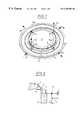
- FIG. 2shows an illustration of the functional principle for the generation of tensile and compressive forces on the deformable inner ring on which the optical element is mounted
- FIG. 3shows a diagrammatic illustration of a mechanical tensile unit for generating a tensile force
- FIG. 4shows a diagrammatic illustration of a mechanical compressive unit for generating a compressive force.
- the optical elemente.g. a lens 1 (only partially shown in FIG. 2, but illustrated in full in FIG. 1) is mounted on a multiplicity of bearing feet 3 which are of angular design and are distributed uniformly over the circumference of an inner ring 2 .
- Those parts 4 of the bearing feet 3which are in each case connected to the inner ring 2 lie parallel to the optical axis.
- Inwardly directed intermediate parts 5 of the bearing feet 3which have bearing surfaces 6 for the lens 1 , run at right angles to the optical axis.
- This design of the bearing feet 3on the one hand provides an accurate mounting and, on the other hand, also provides elasticity in order for deformations to be introduced onto the lens 1 as optical element.
- a mount 7which surrounds the inner ring 2 , there are two actuators which are 180° opposite one another and are in the form of tensile units 8 a and 8 b which generate tensile forces acting in the radial direction, i.e. perpendicular to the optical axis.
- Two further compressive units 9 a , 9 bwhich generate compressive forces, likewise in the radial direction, are also positioned 180° opposite one another, and offset through 90° with respect to the tensile units.
- the tensile and compressive unitsare only diagrammatically indicated in FIG. 1 and are described with regard to their broad functional principle in FIG. 3 and 4 below.
- connection 10by means of which the inner ring 2 is fixedly connected to the mount 7 , is located centrally between in each case two tensile and compressive units which are offset by 90° with respect to one another, i.e. this connection is in each case at 45° between said units.
- the connectionmay be of any desired form. In FIG. 1, these connections are likewise only diagrammatically depicted, and only three of the four connections 10 are visible, owing to the perspective illustration.
- the radial tensile/compressive forces applied by the tensile and compressive units 8 a , 8 b and 9 a , 9 b , corresponding to arrow direction 11 in FIG. 2,are converted in the following way into forces which act parallel to the Z-axis and product astigmatism.
- a lever transmission with elbow levers 12is provided, said levers being located between the inner ring 2 and the mount 7 .
- the elbow levers 12are each T-shaped in cross section, with the crossbar of the T extending at right angles to the optical axis.
- the elbow lever 12is connected in a resilient or articulated manner to the mount 7 , and at the other end, facing toward the inner ring 2 , is connected to the inner ring 2 in a corresponding articulated manner.
- lever arm 13which extends perpendicular to said crossbar and parallel to the Z-axis and on which the tensile and compressive forces 11 from the tensile and compressive units 8 a , 8 b and 9 a , 9 b act.
- elbow levers 12are provided, distributed at intervals of 90° over the circumference. This means that, together with the four connections 10 , the inner ring 2 is elastically connected to the mount 7 via a total of eight connection points. Pockets 14 between the inner ring 2 and the mount 7 can be seen in FIG. 1, in which pockets the elbow levers 12 are fitted.
- the tensile and compressive forces illustrated in FIGS. 3 and 4 at the same timealso produce a transmission in such a manner that a large displacement is converted into a sensitive adjustment of the lens 1 .
- Transmission ratioscan be varied easily, in part by selecting the lever lengths.
- the tensile and compressive units 8 a , 8 b and 9 a , 9 bwhich are illustrated in FIGS. 3 and 4, FIG. 3 showing a tensile unit and FIG. 4 showing a compressive unit, have a spindle drive 16 which is held in the mount 7 .
- the spindle nut 17 of the spindle drive 16is connected to a guide sleeve 18 which is likewise held in the mount 7 .
- One end of a tension spring 19is connected to the guide sleeve 18 , while its other end acts on the lever arm 13 of the elbow lever 12 .
- the spindle drive 16is rotated in such a manner that a translational movement in the direction of arrow 8 a , 8 b is produced via the spindle nut 17 and therefore also for the guide sleeve 18 .
- a suitably “soft” tension spring 19it is possible, by converting a large movement, i.e. with a plurality of spindle rotations, into a small movement, resulting in a slight or sensitive adjustment force in the direction of arrow 15 a.
- a prestressing spring 20may also be provided in order to balance the tension spring 19 .
- the way in which the spindle drive 16 is secured in the mount 7is illustrated diagrammatically by means of a wheel 21 and sliding bearings 22 for the guide sleeve 18 .
- the compressive unit illustrated in FIG. 4is of fundamentally similar structure and also contains the same components.
- a compression spring 23is provided instead of a tension spring 19 , which compression spring, when the spindle drive 16 is rotated, resulting in a translational movement of the spindle nut 17 with the guide sleeve 18 , generates a movement in the direction of arrow 9 a , 9 b .
- An upwardly directed force 15 b acting on the lens 1is the result, via the lever arm 13 of the elbow lever 12 on which a pressure rod 24 , which is connected to the compression spring 23 , acts.
- the compression spring 23 and the pressure rod 24require the provision of additional mounting or guidance 25 on the pressure rod 24 .
- hydraulic unitsmay also be used instead of the mechanical tensile and compressive units which have been described in principle in FIGS. 3 and 4 in order to generate the forces 15 a and 15 b .
- a piezo-driveis also conceivable.
Landscapes
- Physics & Mathematics (AREA)
- General Physics & Mathematics (AREA)
- Health & Medical Sciences (AREA)
- Epidemiology (AREA)
- Optics & Photonics (AREA)
- Public Health (AREA)
- Engineering & Computer Science (AREA)
- Environmental & Geological Engineering (AREA)
- Life Sciences & Earth Sciences (AREA)
- Atmospheric Sciences (AREA)
- Toxicology (AREA)
- Exposure And Positioning Against Photoresist Photosensitive Materials (AREA)
- Exposure Of Semiconductors, Excluding Electron Or Ion Beam Exposure (AREA)
- Mounting And Adjusting Of Optical Elements (AREA)
- Lens Barrels (AREA)
Abstract
Description
The invention relates to an optical system, in particular a projection-illumination unit used in microlithography, of the type defined in more detail in the preamble ofclaim 1.
EP 0 678 768 A2 has described an optical system of the type described in the introduction, in which stepping and scanning processes are employed and only a narrow, slot-like strip is transmitted from a mask to a waver. To illuminate the entire field, a reticle and the waver are displaced laterally (scanning).
However, a drawback of the optical system according to this prior art is that the slot geometry results in a rotationally asymmetric illumination replication especially on lenses which are close to the waver. This means that the temperature distribution which results from the inevitable heating of the lens is likewise rotationally asymmetrical on the lens, and therefore, owing to the linear correlation between refractive index and temperature and owing to thermal expansion, image errors, such as for example astigmatism, arise on the optical axis.
A further problem with an optical system of this nature is the so-called compaction effect, i.e. aging caused by the irradiation, and this effect likewise leads to image errors.
In EP 0 678 768 A2, it is proposed to use a lens as a “final control element”, in order to correct the image error which is produced by uneven heating of the lens. For this purpose, forces which act in the radial direction are allowed to act on the lens. However, a drawback of this solution is that only compressive forces are generated, resulting in an asymmetric change in thickness.
EP 0 660 169 A1 has described a projection-illumination unit which is used in microlithography and in which objectives are provided with correction elements. These include a pair of lenses which can be rotated about the optical axis. In this case, the refractive power from the shape of the lens is altered by superimposing a cylindrical meniscus shape on a spherical lens.
The present invention is based on the object of providing an optical system of the type mentioned at the outset in which image errors, such as those which are formed, for example, by uneven temperature distribution and/or the compaction effect, can be corrected or at least significantly reduced by means of controlled astigmatism.
According to the invention, this object is achieved by means of the features listed in the defining part ofclaim 1.
In contrast to the prior art, not only compressive forces, which result only in an asymmetric change in thickness, are produced, but also, by means of controlled tensile and/or compressive forces, the optical element, e.g. a lens, is deformed, this deformation being selected in such a way that image errors which arise can be compensated to a very substantial extent.
In one configuration according to the invention, it is possible, for the force-displacement transmission, to provide a lever transmission with a lever, at least one actuator acting on one end of the lever and the lever, at another end which is directed toward the inner ring, acting on the inner ring, in such a manner that a force which is parallel to the optical axis is generated on the inner ring.
By suitably arranging or distributing the tensile and compressive forces, which are accordingly distributed over the circumference, it is possible to produce, for example, a dual ripple for the inner ring which supports the lens, and therefore also for the lens. This is the case in particular if the tensile and compressive forces are in each case 180° opposite one another, with tensile and compressive forces in each case alternating at 90° intervals and the inner ring being fixedly connected to the mount by means of connections which are in each case located between these forces.
The astigmatism which is produced in this way makes it possible to substantially compensate for image errors. In practice, the optical element, such as for example a lens, assumes a saddle-like form with the deformation produced in this way.
If necessary, it is also possible to provide “over-compensation”, in order in this way to correct additional compensation for production defects or image errors from other optical elements in the system. In this way, it is possible, overall, to provide compensation for an entire objective or an illumination unit using simple means.
Various energy generators for generating the tensile and compressive forces are possible; generally, in order to increase the accuracy or to provide an appropriate precision adjustment, a lever transmission will be employed. As simple tensile and compressive force generators, it is possible to use actuators in the form of piezo-units or of hydraulic units or, advantageously, mechanical tensile and compressive units which can be arranged in the mount in a simple structure. This measure allows the mount at the same time to be used to seal the hydraulics or to accommodate the tensile and compressive units.
Advantageous refinements and configurations will emerge from the remaining subclaims and from the exemplary embodiment which is described in principle below with reference to the drawing, in which:
FIG. 1 shows a perspective illustration of an optical system with an inner ring which is connected to a mount,
FIG. 2 shows an illustration of the functional principle for the generation of tensile and compressive forces on the deformable inner ring on which the optical element is mounted,
FIG. 3 shows a diagrammatic illustration of a mechanical tensile unit for generating a tensile force, and
FIG. 4 shows a diagrammatic illustration of a mechanical compressive unit for generating a compressive force.
Since a projection-illumination unit is generally known in the field of microlithography, the following text only describes anoptical element 1 which is fitted in a unit of this nature and which, for this purpose, is mounted in or on an inner ring2 which is connected to amount 7.
The optical element, e.g. a lens1 (only partially shown in FIG. 2, but illustrated in full in FIG. 1) is mounted on a multiplicity of bearing feet3 which are of angular design and are distributed uniformly over the circumference of an inner ring2. Thoseparts 4 of the bearing feet3 which are in each case connected to the inner ring2 lie parallel to the optical axis. Inwardly directedintermediate parts 5 of the bearing feet3, which have bearingsurfaces 6 for thelens 1, run at right angles to the optical axis. This design of the bearing feet3 on the one hand provides an accurate mounting and, on the other hand, also provides elasticity in order for deformations to be introduced onto thelens 1 as optical element.
In amount 7 which surrounds the inner ring2, there are two actuators which are 180° opposite one another and are in the form oftensile units compressive units
Aconnection 10, by means of which the inner ring2 is fixedly connected to themount 7, is located centrally between in each case two tensile and compressive units which are offset by 90° with respect to one another, i.e. this connection is in each case at 45° between said units. The connection may be of any desired form. In FIG. 1, these connections are likewise only diagrammatically depicted, and only three of the fourconnections 10 are visible, owing to the perspective illustration.
The radial tensile/compressive forces applied by the tensile andcompressive units arrow direction 11 in FIG. 2, are converted in the following way into forces which act parallel to the Z-axis and product astigmatism.
As can be seen from FIG. 2, for this purpose a lever transmission withelbow levers 12 is provided, said levers being located between the inner ring2 and themount 7. Theelbow levers 12 are each T-shaped in cross section, with the crossbar of the T extending at right angles to the optical axis. At one end of the lever or of the crossbar of the T, theelbow lever 12 is connected in a resilient or articulated manner to themount 7, and at the other end, facing toward the inner ring2, is connected to the inner ring2 in a corresponding articulated manner. Between the two ends of the crossbar of the T, there is alever arm 13 which extends perpendicular to said crossbar and parallel to the Z-axis and on which the tensile andcompressive forces 11 from the tensile andcompressive units
In accordance with the number and arrangement of the tensile andcompressive units elbow levers 12 are provided, distributed at intervals of 90° over the circumference. This means that, together with the fourconnections 10, the inner ring2 is elastically connected to themount 7 via a total of eight connection points.Pockets 14 between the inner ring2 and themount 7 can be seen in FIG. 1, in which pockets theelbow levers 12 are fitted.
Depending on thearrow direction 11 in which the force acts, in the exemplary embodiment forces which are alternately directed downward or upward over the circumference are produced on the inner ring2, in accordance with thearrows 15a(directed downward) and15b(directed upward) which are illustrated in FIG.1.
In principle, it is also possible to generate astigmatism by means only of tensile or compressive forces, i.e. only upwardly or downwardly directed forces, but the selected design in alternating form, due to thefixed connection 10 located between each of these points of action for the forces, results in a dual ripple or saddle shape in thelens 1, with the advantage that there is then no displacement of thelens 1 in the Z-direction.
The tensile and compressive forces illustrated in FIGS. 3 and 4 at the same time also produce a transmission in such a manner that a large displacement is converted into a sensitive adjustment of thelens 1. Transmission ratios can be varied easily, in part by selecting the lever lengths.
The tensile andcompressive units spindle drive 16 which is held in themount 7. Thespindle nut 17 of thespindle drive 16 is connected to aguide sleeve 18 which is likewise held in themount 7. One end of atension spring 19 is connected to theguide sleeve 18, while its other end acts on thelever arm 13 of theelbow lever 12. To produce downwardly directedforces 15aon thelens 1, thespindle drive 16 is rotated in such a manner that a translational movement in the direction ofarrow spindle nut 17 and therefore also for theguide sleeve 18. If a suitably “soft”tension spring 19 is used, it is possible, by converting a large movement, i.e. with a plurality of spindle rotations, into a small movement, resulting in a slight or sensitive adjustment force in the direction ofarrow 15a.
If necessary, aprestressing spring 20 may also be provided in order to balance thetension spring 19. The way in which thespindle drive 16 is secured in themount 7 is illustrated diagrammatically by means of awheel 21 and slidingbearings 22 for theguide sleeve 18.
The compressive unit illustrated in FIG. 4 is of fundamentally similar structure and also contains the same components. In this case, however, acompression spring 23 is provided instead of atension spring 19, which compression spring, when thespindle drive 16 is rotated, resulting in a translational movement of thespindle nut 17 with theguide sleeve 18, generates a movement in the direction ofarrow force 15bacting on thelens 1 is the result, via thelever arm 13 of theelbow lever 12 on which apressure rod 24, which is connected to thecompression spring 23, acts. In addition to the mounting shown in FIG. 3, thecompression spring 23 and thepressure rod 24 require the provision of additional mounting orguidance 25 on thepressure rod 24.
Naturally, hydraulic units may also be used instead of the mechanical tensile and compressive units which have been described in principle in FIGS. 3 and 4 in order to generate theforces
Claims (9)
1. An optical system, in particular a projection-illumination unit used in microlithography, in particular with a slot-shaped filed of view or non-rotationally symmetrical illumination, which has an optical element, in particular a lens or a mirror, which is arranged in a mount or an inner ring, and actuators which act on the optical element and/or the inner ring, wherein a plurality of actuators act on the deformable inner ring via a radial force-displacement transmission to generate a force parallel to the optical axis on the inner ring.
2. The optical system as claimed in claim1, wherein a lever transmission with a lever is provided for the force-displacement transmission, at least one actuator acting on one end of the lever and the lever, at another end which is directed toward the inner ring, acting on the inner ring.
3. The optical system as claimed in claim1, wherein tensile or compressive forces which are in each case 180° opposite one another act on levers, tensile and compressive forces in each case alternating at 90° intervals, and the inner ring being fixedly connected to the mount by means of connections which are in each case located between these forces.
4. The optical system as claimed in claim2, wherein the levers are designed as elbow levers which are arranged at intervals of 90° between the inner ring and the mount, the elbow levers, on their outer circumference, being resiliently connected to the mount and, on their inner circumference, acting, in an articulated manner, on the inner ring, and the actuators each acting on a lever arm, which runs parallel to the optical axis, of the elbow levers.
5. The optical system as claimed in claim1, wherein angled bearing feet are distributed over the circumference of the inner ring, those parts of the feet which are connected to the inner ring being oriented parallel to the optical axis, and intermediate parts which run inward at right angels to this axis having bearing surfaces for the optical element.
6. The optical system as claimed in claim1, wherein the actuators are designed as mechanical tension and compression units.
7. The optical system as claimed in claim6, wherein the tension and compression units are provided with a spindle drive, it being possible to exert a tensile and compressive force, via the spindle nut, on a spring device which acts on the associated lever.
8. The optical system as claimed in claim7, wherein the spring device is used to convert a large adjustment displacement into a fine adjustment on the lever.
9. The optical system as claimed in claim8, characterized in that the tension and compression units are arranged in holes in the mount.
Applications Claiming Priority (2)
| Application Number | Priority Date | Filing Date | Title |
|---|---|---|---|
| DE19859634 | 1998-12-23 | ||
| DE19859634ADE19859634A1 (en) | 1998-12-23 | 1998-12-23 | Optical system, in particular projection exposure system for microlithography |
Publications (1)
| Publication Number | Publication Date |
|---|---|
| US6307688B1true US6307688B1 (en) | 2001-10-23 |
Family
ID=7892366
Family Applications (1)
| Application Number | Title | Priority Date | Filing Date |
|---|---|---|---|
| US09/444,815Expired - LifetimeUS6307688B1 (en) | 1998-12-23 | 1999-11-22 | Optical system, in particular projection-illumination unit used in microlithography |
Country Status (6)
| Country | Link |
|---|---|
| US (1) | US6307688B1 (en) |
| EP (1) | EP1014139B1 (en) |
| JP (1) | JP2000195788A (en) |
| KR (1) | KR100733935B1 (en) |
| DE (2) | DE19859634A1 (en) |
| TW (1) | TW518428B (en) |
Cited By (67)
| Publication number | Priority date | Publication date | Assignee | Title |
|---|---|---|---|---|
| US20020021507A1 (en)* | 2000-06-21 | 2002-02-21 | Frank Melzer | Method of connecting a multiplicity of optical elements to a basic body |
| US6441975B1 (en)* | 1999-12-10 | 2002-08-27 | Carl-Zeiss-Stiftung | Device for the low-deformation support of an optical element and method for the low-deformation support of the optical element |
| US20020149848A1 (en)* | 2001-04-10 | 2002-10-17 | Rainer Labus | Device and method for changing the stress-induced birefringence and/or the thickness of an optical component |
| US20020163741A1 (en)* | 2000-08-18 | 2002-11-07 | Yuichi Shibazaki | Optical element holding device |
| US20030058551A1 (en)* | 2001-09-22 | 2003-03-27 | Carl-Zeiss Semiconductor Manufacturing Technologies Ag | Mount for an optical element in an optical imaging device |
| US6560045B1 (en)* | 1999-10-06 | 2003-05-06 | Jenoptik Aktiengesellschaft | Elastic lens holder |
| US6580570B2 (en)* | 2000-10-18 | 2003-06-17 | Carl-Zeiss-Stiftung | Mounting apparatus for an optical element |
| US20030144702A1 (en)* | 1998-05-08 | 2003-07-31 | Yinghong Yu | Method and apparatus for optimizing stroke volume during DDD resynchronization therapy using adjustable atrio-ventricular delays |
| US20030169517A1 (en)* | 2002-03-05 | 2003-09-11 | Ulrich Weber | Objective, in particular a projection lens for microlithography |
| US20040008419A1 (en)* | 1995-05-12 | 2004-01-15 | Schachar Ronald A. | Variable focus lens by small changes of the equatorial lens diameter |
| US20040105177A1 (en)* | 2002-08-09 | 2004-06-03 | Ryuichi Ebinuma | Method of supporting and adjusting optical element in exposure apparatus |
| US20040105170A1 (en)* | 2001-05-15 | 2004-06-03 | Carl Zeiss Smt Ag | Objective with fluoride crystal lenses |
| WO2004057398A1 (en)* | 2002-12-23 | 2004-07-08 | Bae Systems Plc | Deformable-mirror holder |
| US20040150806A1 (en)* | 2001-05-15 | 2004-08-05 | Martin Brunotte | Projection lens and microlithographic projection exposure apparatus |
| US20040174619A1 (en)* | 2001-08-18 | 2004-09-09 | Carl Zeiss Smt Ag | Adjustment arrangement of an optical element |
| US20040201909A1 (en)* | 2001-07-26 | 2004-10-14 | Alexander Kohl | Objective, particularly a projection objective for use in semiconductor lithography |
| US20040214483A1 (en)* | 2003-04-25 | 2004-10-28 | Makoto Mizuno | Driving apparatus, optical system, exposure apparatus and device fabrication method |
| US20040212873A1 (en)* | 2002-09-18 | 2004-10-28 | Hwang Seong-Taek | Wideband optical fiber amplifier |
| US6816325B1 (en) | 2003-09-11 | 2004-11-09 | Carl Zeiss Smt Ag | Mounting apparatus for an optical element |
| US20050018311A1 (en)* | 2003-07-11 | 2005-01-27 | Ernst-Dieter Knohl | Method of producing aspherical optical surfaces |
| WO2004057406A3 (en)* | 2002-12-23 | 2005-03-24 | Bae Systems Plc | Deformable-mirror cooling |
| US20050134972A1 (en)* | 2003-12-23 | 2005-06-23 | Jens Kugler | Replacement apparatus for an optical element |
| US20050157401A1 (en)* | 2001-05-15 | 2005-07-21 | Aksel Goehnermeier | Objective with crystal lenses |
| US6930842B2 (en)* | 2000-03-31 | 2005-08-16 | Nikon Corporation | Optical element holding device for exposure apparatus |
| EP1378797A3 (en)* | 2002-06-21 | 2005-09-07 | Nikon Corporation | Wavefront aberration correction system |
| US20050237506A1 (en)* | 2004-04-09 | 2005-10-27 | Carl Zeiss Smt Ag | Method of optimizing imaging performance |
| US20060018045A1 (en)* | 2003-10-23 | 2006-01-26 | Carl Zeiss Smt Ag | Mirror arrangement and method of manufacturing thereof, optical system and lithographic method of manufacturing a miniaturized device |
| US20060077579A1 (en)* | 2004-10-12 | 2006-04-13 | Margeson Christopher S | Force actuator with clamp |
| US20060103956A1 (en)* | 2002-12-23 | 2006-05-18 | Bae Systems Plc | Deformable mirror |
| US20060139585A1 (en)* | 2004-12-28 | 2006-06-29 | Asml Netherlands B.V. | Lithographic apparatus and device manufacturing method |
| US20060139775A1 (en)* | 2003-06-06 | 2006-06-29 | Nikon Corporation | Optical element holding device, lens barrel, exposing device, and device producing method |
| US20060146427A1 (en)* | 2001-12-20 | 2006-07-06 | Birgit Kurz | Method for improving the imaging properties of at least two optical elements and photolithographic fabrication method |
| US20060158707A1 (en)* | 2004-12-28 | 2006-07-20 | Tilmann Schwertner | Mount for an optical element, method for fitting an optical element on a mount and method for manipulating an optical device |
| EP1720068A1 (en)* | 2004-05-04 | 2006-11-08 | Carl Zeiss SMT AG | Highly reproducible positioning low torque mirror-actuator interface |
| US20060279856A1 (en)* | 2005-05-16 | 2006-12-14 | Carl Zeiss Smt Ag | Optical apparatus comprising an optical component and an adjustment device and method for influencing a polarization state of the optical component |
| US20070036494A1 (en)* | 2004-02-20 | 2007-02-15 | Carl Zeiss Smt Ag | Projection objective of a microlithographic projection exposure apparatus |
| US7196841B2 (en) | 2002-04-30 | 2007-03-27 | Carl Zeiss Smt Ag | Lighting system, particularly for use in extreme ultraviolet (EUV) lithography |
| US20070183064A1 (en)* | 2003-12-25 | 2007-08-09 | Yuichi Shibazaki | Apparatus for holding optical element, barrel, exposure apparatus, and device producing method |
| US20080002170A1 (en)* | 2003-11-24 | 2008-01-03 | Bernhard Gellrich | Holding Device for an Optical Element in an Objective |
| US20080024729A1 (en)* | 2006-07-27 | 2008-01-31 | Young Optics Inc. | Projection apparatus |
| US20080170303A1 (en)* | 2005-01-26 | 2008-07-17 | Carl Zeiss Smt Ag | Optical Assembly |
| DE102007005203A1 (en) | 2007-01-29 | 2008-07-31 | Carl Zeiss Smt Ag | Holder for optical element and for use with lithography objective, has actuator for indirectly moving optical element, where actuator is formed as bimorphes, piezoelectric element, and optical element takes up inner ring and outer ring |
| US20080204682A1 (en)* | 2005-06-28 | 2008-08-28 | Nikon Corporation | Exposure method and exposure apparatus, and device manufacturing method |
| US20080246933A1 (en)* | 2004-02-13 | 2008-10-09 | Nikon Corporation | Exposure Method And Apparatus, And Device Production Method |
| US20080285002A1 (en)* | 2005-12-03 | 2008-11-20 | Carl Zeiss Smt Ag | Projection objective for semiconductor lithography |
| DE102007047109A1 (en) | 2007-10-01 | 2009-04-09 | Carl Zeiss Smt Ag | Optical system, in particular projection lens of microlithography |
| US20090122288A1 (en)* | 2003-03-26 | 2009-05-14 | Carl Zeiss Smt Ag | Device for the low-deformation replaceable mounting of an optical element |
| WO2009061578A1 (en)* | 2007-11-09 | 2009-05-14 | Nikon Corporation | Reflective optical elements exhibiting multimetallic-like self-correction of distortions caused by heating |
| US20090174876A1 (en)* | 2006-07-24 | 2009-07-09 | Carl Zeiss Smt Ag | Optical apparatus and method for modifying the imaging behavior of such apparatus |
| US20090257032A1 (en)* | 2006-09-21 | 2009-10-15 | Carl Zeiss Smt Ag | Optical element and method |
| US20090310107A1 (en)* | 2008-06-11 | 2009-12-17 | Canon Kabushiki Kaisha | Deforming mechanism, exposure apparatus, and device manufacturing method |
| US20100128367A1 (en)* | 2006-09-28 | 2010-05-27 | Carl Zeiss Smt Ag | Projection objective for a microlithography apparatus and method |
| US20100157246A1 (en)* | 2008-12-23 | 2010-06-24 | Carl Zeiss Surgical Gmbh | Ophthalmic surgical system |
| US20100201958A1 (en)* | 2007-08-24 | 2010-08-12 | Carl Zeiss Smt Ag | Optical correction device |
| US7791711B2 (en) | 2002-04-29 | 2010-09-07 | Carl Zeiss Smt Ag | Projection method including pupillary filtering and a projection lens therefor |
| US7817249B2 (en) | 2003-08-28 | 2010-10-19 | Nikon Corporation | Exposure method and apparatus, and device producing method using two light beams to correct non-rotationally symmetric aberration |
| KR101012998B1 (en)* | 2008-08-06 | 2011-02-10 | 경북대학교 산학협력단 | Biomimetic Robot Eye Assembly |
| US20110098991A1 (en)* | 2007-08-14 | 2011-04-28 | Moondog Optics, Inc. | System for reducing the effects of component misalignment in an optical system |
| US20110279802A1 (en)* | 2010-05-12 | 2011-11-17 | Carl Zeiss Smt Gmbh | Device for an optical arrangement and method for positioning an optical element of an optical arrangement |
| US8710471B2 (en) | 2008-04-03 | 2014-04-29 | Carl Zeiss Smt Gmbh | Projection illumination system for EUV microlithography |
| US9217936B2 (en) | 2008-07-14 | 2015-12-22 | Carl Zeiss Smt Gmbh | Optical device having a deformable optical element |
| US9366977B2 (en) | 2009-05-16 | 2016-06-14 | Carl Zeiss Smt Gmbh | Semiconductor microlithography projection exposure apparatus |
| US9366857B2 (en) | 2007-03-27 | 2016-06-14 | Carl Zeiss Smt Gmbh | Correction of optical elements by correction light irradiated in a flat manner |
| DE102015223520A1 (en) | 2015-11-27 | 2016-10-20 | Carl Zeiss Smt Gmbh | Projection exposure apparatus for semiconductor lithography |
| US10025200B2 (en) | 2014-05-14 | 2018-07-17 | Carl Zeiss Smt Gmbh | Optimum arrangement of actuator and sensor points on an optical element |
| US20190154948A1 (en)* | 2016-04-29 | 2019-05-23 | Shanghai Micro Electronics Equipment (Group) Co., Ltd. | Side vertical mirror group and installation method thereof |
| WO2025077081A1 (en)* | 2023-10-10 | 2025-04-17 | 北京国望光学科技有限公司 | Image quality compensation device |
Families Citing this family (21)
| Publication number | Priority date | Publication date | Assignee | Title |
|---|---|---|---|---|
| EP1277071B1 (en) | 2000-04-25 | 2008-01-09 | ASML Holding N.V. | Apparatus, system and method for precision positioning and alignment of a lens in an optical system |
| DE10151919B4 (en)* | 2001-10-20 | 2007-02-01 | Carl Zeiss Smt Ag | Exposure lens in semiconductor lithography |
| TWI454731B (en) | 2005-05-27 | 2014-10-01 | Zeiss Carl Smt Gmbh | Method for improving the imaging properties of a projection objective, and such a projection objective |
| WO2007017089A1 (en) | 2005-07-25 | 2007-02-15 | Carl Zeiss Smt Ag | Projection objective of a microlithographic projection exposure apparatus |
| JP2007266511A (en)* | 2006-03-29 | 2007-10-11 | Nikon Corp | Optical system, exposure apparatus, and method for adjusting optical characteristics |
| DE102006047665A1 (en)* | 2006-09-28 | 2008-04-03 | Carl Zeiss Smt Ag | Optical system e.g. lighting system, for microlithography system, has optical unit supported by retaining units, and actuator incorporating force and/or moment to trigger isotropy-stress voltages to produce voltage birefringence in unit |
| JP5171061B2 (en) | 2007-02-20 | 2013-03-27 | キヤノン株式会社 | Drive mechanism |
| DE102007014155A1 (en)* | 2007-03-20 | 2008-09-25 | Jenoptik Laser, Optik, Systeme Gmbh | Optics socket and optical component with such an optical socket |
| EP2189832A1 (en)* | 2008-11-20 | 2010-05-26 | BAE Systems PLC | Deformable Mirror Suspension |
| WO2010058204A1 (en)* | 2008-11-20 | 2010-05-27 | Bae Systems Plc | Deformable mirror suspension |
| JP2010219080A (en)* | 2009-03-13 | 2010-09-30 | Canon Inc | Optical device, stage device, optical system, and exposure apparatus |
| FR2963439B1 (en)* | 2010-07-30 | 2012-09-14 | Sagem Defense Securite | PASSIVE MECHANICAL ATHERENT DEVICE, OPTICAL SYSTEM THEREFOR |
| DE102011053566B4 (en)* | 2011-09-13 | 2022-06-23 | HELLA GmbH & Co. KGaA | lens device |
| JP5904749B2 (en)* | 2011-10-14 | 2016-04-20 | キヤノン株式会社 | Optical element holding device, lens device having the same, and imaging device |
| DE102014209147A1 (en) | 2014-05-14 | 2015-11-19 | Carl Zeiss Smt Gmbh | Optical module |
| DE102014209150A1 (en) | 2014-05-14 | 2015-07-02 | Carl Zeiss Smt Gmbh | Optical module |
| DE102014209151A1 (en) | 2014-05-14 | 2015-07-02 | Carl Zeiss Smt Gmbh | Optical module |
| DE102014209160A1 (en) | 2014-05-14 | 2015-11-19 | Carl Zeiss Smt Gmbh | Optical module |
| DE102014209149A1 (en) | 2014-05-14 | 2015-10-08 | Carl Zeiss Smt Gmbh | Optical module |
| DE102019112224A1 (en) | 2019-05-10 | 2020-11-12 | Carl Zeiss Smt Gmbh | Support of an optical element |
| CN110275271B (en)* | 2019-07-15 | 2021-09-14 | 北京遥感设备研究所 | Connecting structure of reflector and rotating shaft |
Citations (9)
| Publication number | Priority date | Publication date | Assignee | Title |
|---|---|---|---|---|
| US3957359A (en)* | 1975-01-23 | 1976-05-18 | Meginnis Charles E | Sight glass assembly |
| US4017878A (en) | 1974-07-05 | 1977-04-12 | Asahi Kogaku Kogyo Kabushiki Kaisha | Bayonet mount adapter for a camera |
| US4161120A (en) | 1978-05-08 | 1979-07-17 | Wabco Westinghouse | Equipment for the detection of rotation parameters in particular for a wheel-velocity sensor |
| US5249082A (en)* | 1991-05-08 | 1993-09-28 | Eastman Kodak Company | Exact constraint arrangement for and methods of mounting an element such as a lens |
| EP0660169A1 (en) | 1993-12-22 | 1995-06-28 | Nikon Corporation | Projection exposure apparatus |
| EP0678768A2 (en) | 1994-04-22 | 1995-10-25 | Canon Kabushiki Kaisha | Projection exposure apparatus and microdevice manufacturing method |
| US5521764A (en)* | 1994-01-14 | 1996-05-28 | Jenoptik Gmbh | Device for lateral adjustment of lenses in a high-performance lens system |
| US5774274A (en)* | 1995-05-12 | 1998-06-30 | Schachar; Ronald A. | Variable focus lens by small changes of the equatorial lens diameter |
| US5966248A (en)* | 1996-10-16 | 1999-10-12 | Nikon Corporation | Lens driving mechanism having an actuator |
Family Cites Families (29)
| Publication number | Priority date | Publication date | Assignee | Title |
|---|---|---|---|---|
| US4043644A (en)* | 1976-07-15 | 1977-08-23 | Humphrey Instruments, Inc. | Elastically compensated off-axis mirror |
| US4196972A (en)* | 1977-08-22 | 1980-04-08 | The Perkin-Elmer Corporation | Configuration control apparatus |
| JPS568101A (en)* | 1979-07-02 | 1981-01-27 | Hitachi Ltd | Electro-optical lens |
| US4540251A (en)* | 1983-12-01 | 1985-09-10 | International Business Machines Corporation | Thermo-mechanical overlay signature tuning for Perkin-Elmer mask aligner |
| JPS6235619A (en)* | 1985-08-09 | 1987-02-16 | Canon Inc | projection exposure equipment |
| US4647164A (en)* | 1985-11-21 | 1987-03-03 | The United States Of America As Represented By The United States Department Of Energy | Apparatus for and method of correcting for astigmatism in a light beam reflected off of a light reflecting surface |
| US4733945A (en)* | 1986-01-15 | 1988-03-29 | The Perkin-Elmer Corporation | Precision lens mounting |
| JPS62291920A (en)* | 1986-06-12 | 1987-12-18 | Nikon Corp | Projection optical device |
| JP2641331B2 (en)* | 1990-08-15 | 1997-08-13 | 三菱電機株式会社 | Reflector antenna method |
| EP0480616B1 (en)* | 1990-10-08 | 1997-08-20 | Canon Kabushiki Kaisha | Projection exposure apparatus with an aberration compensation device of a projection lens |
| US5210650A (en)* | 1992-03-31 | 1993-05-11 | Eastman Kodak Company | Compact, passively athermalized optical assembly |
| JP3259373B2 (en)* | 1992-11-27 | 2002-02-25 | 株式会社日立製作所 | Exposure method and exposure apparatus |
| JP3251362B2 (en)* | 1993-01-11 | 2002-01-28 | 三菱電機株式会社 | Exposure apparatus and exposure method |
| US5383168A (en)* | 1993-04-01 | 1995-01-17 | Eastman Kodak Company | Actively athermalized optical head assembly |
| JPH06313833A (en)* | 1993-04-30 | 1994-11-08 | Toshiba Corp | Optical device |
| JPH0786152A (en)* | 1993-09-14 | 1995-03-31 | Nikon Corp | Projection exposure device |
| US5557469A (en)* | 1994-10-28 | 1996-09-17 | Ultratech Stepper, Inc. | Beamsplitter in single fold optical system and optical variable magnification method and system |
| US5684566A (en)* | 1995-05-24 | 1997-11-04 | Svg Lithography Systems, Inc. | Illumination system and method employing a deformable mirror and diffractive optical elements |
| JP3894509B2 (en)* | 1995-08-07 | 2007-03-22 | キヤノン株式会社 | Optical apparatus, exposure apparatus, and device manufacturing method |
| JP3632264B2 (en)* | 1995-11-30 | 2005-03-23 | 株式会社ニコン | X-ray projection exposure apparatus |
| JPH1039208A (en)* | 1996-07-23 | 1998-02-13 | Nikon Corp | Projection optical system |
| JPH1054932A (en)* | 1996-08-08 | 1998-02-24 | Nikon Corp | Projection optical apparatus and projection exposure apparatus equipped with the same |
| DE19637563A1 (en)* | 1996-09-14 | 1998-03-19 | Zeiss Carl Fa | Birefringent faceplate arrangement and DUV quarter-wave plate |
| JPH10133150A (en)* | 1996-10-29 | 1998-05-22 | Canon Inc | Diffractive optical apparatus and exposure apparatus using the same |
| JPH10206714A (en)* | 1997-01-20 | 1998-08-07 | Canon Inc | Lens moving device |
| JP3445105B2 (en)* | 1997-07-25 | 2003-09-08 | キヤノン株式会社 | Optical element moving device |
| DE19825716A1 (en)* | 1998-06-09 | 1999-12-16 | Zeiss Carl Fa | Optical element and socket assembly |
| US5986827A (en)* | 1998-06-17 | 1999-11-16 | The Regents Of The University Of California | Precision tip-tilt-piston actuator that provides exact constraint |
| DE19827603A1 (en)* | 1998-06-20 | 1999-12-23 | Zeiss Carl Fa | Projection light exposure system for microlithography |
- 1998
- 1998-12-23DEDE19859634Apatent/DE19859634A1/ennot_activeWithdrawn
- 1999
- 1999-11-22USUS09/444,815patent/US6307688B1/ennot_activeExpired - Lifetime
- 1999-12-08JPJP11348922Apatent/JP2000195788A/enactivePending
- 1999-12-09EPEP99124503Apatent/EP1014139B1/ennot_activeExpired - Lifetime
- 1999-12-09DEDE59911798Tpatent/DE59911798D1/ennot_activeExpired - Lifetime
- 1999-12-11KRKR1019990056939Apatent/KR100733935B1/ennot_activeExpired - Fee Related
- 1999-12-15TWTW088122486Apatent/TW518428B/ennot_activeIP Right Cessation
Patent Citations (9)
| Publication number | Priority date | Publication date | Assignee | Title |
|---|---|---|---|---|
| US4017878A (en) | 1974-07-05 | 1977-04-12 | Asahi Kogaku Kogyo Kabushiki Kaisha | Bayonet mount adapter for a camera |
| US3957359A (en)* | 1975-01-23 | 1976-05-18 | Meginnis Charles E | Sight glass assembly |
| US4161120A (en) | 1978-05-08 | 1979-07-17 | Wabco Westinghouse | Equipment for the detection of rotation parameters in particular for a wheel-velocity sensor |
| US5249082A (en)* | 1991-05-08 | 1993-09-28 | Eastman Kodak Company | Exact constraint arrangement for and methods of mounting an element such as a lens |
| EP0660169A1 (en) | 1993-12-22 | 1995-06-28 | Nikon Corporation | Projection exposure apparatus |
| US5521764A (en)* | 1994-01-14 | 1996-05-28 | Jenoptik Gmbh | Device for lateral adjustment of lenses in a high-performance lens system |
| EP0678768A2 (en) | 1994-04-22 | 1995-10-25 | Canon Kabushiki Kaisha | Projection exposure apparatus and microdevice manufacturing method |
| US5774274A (en)* | 1995-05-12 | 1998-06-30 | Schachar; Ronald A. | Variable focus lens by small changes of the equatorial lens diameter |
| US5966248A (en)* | 1996-10-16 | 1999-10-12 | Nikon Corporation | Lens driving mechanism having an actuator |
Non-Patent Citations (1)
| Title |
|---|
| Opto-mechanical systems design/Paul R. Yoder, Jr., 2nd Edition, rev. and expanded, vol. 35, 1992. |
Cited By (152)
| Publication number | Priority date | Publication date | Assignee | Title |
|---|---|---|---|---|
| US6930838B2 (en)* | 1995-05-12 | 2005-08-16 | Pc Lens Corp. | Variable focus lens by small changes of the equatorial lens diameter |
| US20040008419A1 (en)* | 1995-05-12 | 2004-01-15 | Schachar Ronald A. | Variable focus lens by small changes of the equatorial lens diameter |
| US20030144702A1 (en)* | 1998-05-08 | 2003-07-31 | Yinghong Yu | Method and apparatus for optimizing stroke volume during DDD resynchronization therapy using adjustable atrio-ventricular delays |
| US6560045B1 (en)* | 1999-10-06 | 2003-05-06 | Jenoptik Aktiengesellschaft | Elastic lens holder |
| US6441975B1 (en)* | 1999-12-10 | 2002-08-27 | Carl-Zeiss-Stiftung | Device for the low-deformation support of an optical element and method for the low-deformation support of the optical element |
| US6930842B2 (en)* | 2000-03-31 | 2005-08-16 | Nikon Corporation | Optical element holding device for exposure apparatus |
| US7034998B2 (en) | 2000-06-21 | 2006-04-25 | Carl Zeiss Smt Ag | Method of connecting a multiplicity of optical elements to a basic body |
| US20020021507A1 (en)* | 2000-06-21 | 2002-02-21 | Frank Melzer | Method of connecting a multiplicity of optical elements to a basic body |
| US7154684B2 (en) | 2000-08-18 | 2006-12-26 | Nikon Corporation | Optical element holding apparatus |
| US7420752B2 (en) | 2000-08-18 | 2008-09-02 | Nikon Corporation | Holding apparatus |
| US20070121224A1 (en)* | 2000-08-18 | 2007-05-31 | Nikon Corporation | Optical element holding apparatus |
| US20020163741A1 (en)* | 2000-08-18 | 2002-11-07 | Yuichi Shibazaki | Optical element holding device |
| US6580570B2 (en)* | 2000-10-18 | 2003-06-17 | Carl-Zeiss-Stiftung | Mounting apparatus for an optical element |
| US20020149848A1 (en)* | 2001-04-10 | 2002-10-17 | Rainer Labus | Device and method for changing the stress-induced birefringence and/or the thickness of an optical component |
| US6937394B2 (en)* | 2001-04-10 | 2005-08-30 | Carl Zeiss Semiconductor Manufacturing Technologies Ag | Device and method for changing the stress-induced birefringence and/or the thickness of an optical component |
| US20050264786A1 (en)* | 2001-05-15 | 2005-12-01 | Martin Brunotte | Projection lens and microlithographic projection exposure apparatus |
| US20040150806A1 (en)* | 2001-05-15 | 2004-08-05 | Martin Brunotte | Projection lens and microlithographic projection exposure apparatus |
| US7145720B2 (en) | 2001-05-15 | 2006-12-05 | Carl Zeiss Smt Ag | Objective with fluoride crystal lenses |
| US20060171020A1 (en)* | 2001-05-15 | 2006-08-03 | Carl Zeiss Smt Ag | Objective with fluoride crystal lenses |
| US7170585B2 (en) | 2001-05-15 | 2007-01-30 | Carl Zeiss Smt Ag | Projection lens and microlithographic projection exposure apparatus |
| US20040105170A1 (en)* | 2001-05-15 | 2004-06-03 | Carl Zeiss Smt Ag | Objective with fluoride crystal lenses |
| US6879379B2 (en) | 2001-05-15 | 2005-04-12 | Carl Zeiss Smt Ag | Projection lens and microlithographic projection exposure apparatus |
| US7239447B2 (en) | 2001-05-15 | 2007-07-03 | Carl Zeiss Smt Ag | Objective with crystal lenses |
| US20050134967A1 (en)* | 2001-05-15 | 2005-06-23 | Carl Zeiss Smt Ag | Projection lens and microlithographic projection exposure apparatus |
| US20050157401A1 (en)* | 2001-05-15 | 2005-07-21 | Aksel Goehnermeier | Objective with crystal lenses |
| US7382536B2 (en) | 2001-05-15 | 2008-06-03 | Carl Zeiss Smt Ag | Objective with fluoride crystal lenses |
| US20040201909A1 (en)* | 2001-07-26 | 2004-10-14 | Alexander Kohl | Objective, particularly a projection objective for use in semiconductor lithography |
| US7123427B2 (en) | 2001-07-26 | 2006-10-17 | Carl Zeiss Smt Ag | Objective, particularly a projection objective for use in semiconductor lithography |
| US20070014038A1 (en)* | 2001-08-18 | 2007-01-18 | Klaus Beck | Adjustment arrangement of an optical element |
| US7457059B2 (en) | 2001-08-18 | 2008-11-25 | Carl Zeiss Smt Ag | Adjustment arrangement of an optical element |
| US7656595B2 (en) | 2001-08-18 | 2010-02-02 | Carl Zeiss Smt Ag | Adjustment arrangement of an optical element |
| US20040174619A1 (en)* | 2001-08-18 | 2004-09-09 | Carl Zeiss Smt Ag | Adjustment arrangement of an optical element |
| US7193794B2 (en) | 2001-08-18 | 2007-03-20 | Carl Zeiss Smt Ag | Adjustment arrangement of an optical element |
| US20090009892A1 (en)* | 2001-08-18 | 2009-01-08 | Carl Zeiss Smt Ag | Adjustment Arrangement of an Optical Element |
| US6744574B2 (en) | 2001-09-22 | 2004-06-01 | Carl Zeiss Semiconductor Manufacturing Technologies Ag | Mount for an optical element in an optical imaging device |
| US20030058551A1 (en)* | 2001-09-22 | 2003-03-27 | Carl-Zeiss Semiconductor Manufacturing Technologies Ag | Mount for an optical element in an optical imaging device |
| US20060146427A1 (en)* | 2001-12-20 | 2006-07-06 | Birgit Kurz | Method for improving the imaging properties of at least two optical elements and photolithographic fabrication method |
| US20030169517A1 (en)* | 2002-03-05 | 2003-09-11 | Ulrich Weber | Objective, in particular a projection lens for microlithography |
| US6724548B2 (en) | 2002-03-05 | 2004-04-20 | Carl Zeiss Smt Ag | Objective, in particular a projection lens for microlithography |
| US7791711B2 (en) | 2002-04-29 | 2010-09-07 | Carl Zeiss Smt Ag | Projection method including pupillary filtering and a projection lens therefor |
| US7196841B2 (en) | 2002-04-30 | 2007-03-27 | Carl Zeiss Smt Ag | Lighting system, particularly for use in extreme ultraviolet (EUV) lithography |
| EP1378797A3 (en)* | 2002-06-21 | 2005-09-07 | Nikon Corporation | Wavefront aberration correction system |
| US20040105177A1 (en)* | 2002-08-09 | 2004-06-03 | Ryuichi Ebinuma | Method of supporting and adjusting optical element in exposure apparatus |
| US7136238B2 (en)* | 2002-08-09 | 2006-11-14 | Canon Kabushiki Kaisha | Method of supporting and adjusting optical element in exposure apparatus |
| US20040212873A1 (en)* | 2002-09-18 | 2004-10-28 | Hwang Seong-Taek | Wideband optical fiber amplifier |
| US7068425B2 (en)* | 2002-09-18 | 2006-06-27 | Samsung Electronics Co., Ltd. | Wideband optical fiber amplifier |
| US20060103955A1 (en)* | 2002-12-23 | 2006-05-18 | Bae Systems Plc | Deformable-mirror cooling |
| WO2004057406A3 (en)* | 2002-12-23 | 2005-03-24 | Bae Systems Plc | Deformable-mirror cooling |
| US7264363B2 (en)* | 2002-12-23 | 2007-09-04 | Bae Systems Plc | Deformable-mirror cooling |
| US7740363B2 (en) | 2002-12-23 | 2010-06-22 | Bae Systems Plc | Deformable-mirror holder |
| US20060082909A1 (en)* | 2002-12-23 | 2006-04-20 | Griffith Michael S | Deformable-mirror holder |
| US7374302B2 (en)* | 2002-12-23 | 2008-05-20 | Bae Systems Plc | Deformable mirror |
| WO2004057398A1 (en)* | 2002-12-23 | 2004-07-08 | Bae Systems Plc | Deformable-mirror holder |
| US20060103956A1 (en)* | 2002-12-23 | 2006-05-18 | Bae Systems Plc | Deformable mirror |
| US20090122288A1 (en)* | 2003-03-26 | 2009-05-14 | Carl Zeiss Smt Ag | Device for the low-deformation replaceable mounting of an optical element |
| US8582081B2 (en)* | 2003-03-26 | 2013-11-12 | Carl Zeiss Smt Gmbh | Device for the low-deformation replaceable mounting of an optical element |
| US7760452B2 (en) | 2003-04-25 | 2010-07-20 | Canon Kabushiki Kaisha | Driving apparatus, optical system, exposure apparatus and device fabrication method |
| US20040214483A1 (en)* | 2003-04-25 | 2004-10-28 | Makoto Mizuno | Driving apparatus, optical system, exposure apparatus and device fabrication method |
| US20060139775A1 (en)* | 2003-06-06 | 2006-06-29 | Nikon Corporation | Optical element holding device, lens barrel, exposing device, and device producing method |
| US20070279768A1 (en)* | 2003-06-06 | 2007-12-06 | Nikon Corporation | Optical Element Holding Device, Lens Barrel, Exposing Device, and Device Producing Method |
| US7764447B2 (en) | 2003-06-06 | 2010-07-27 | Nikon Corporation | Optical element holding device, lens barrel, exposing device, and device producing method |
| US20050018311A1 (en)* | 2003-07-11 | 2005-01-27 | Ernst-Dieter Knohl | Method of producing aspherical optical surfaces |
| US7540983B2 (en) | 2003-07-11 | 2009-06-02 | Carl Zeiss Smt Ag | Method of producing aspherical optical surfaces |
| US7817249B2 (en) | 2003-08-28 | 2010-10-19 | Nikon Corporation | Exposure method and apparatus, and device producing method using two light beams to correct non-rotationally symmetric aberration |
| US6816325B1 (en) | 2003-09-11 | 2004-11-09 | Carl Zeiss Smt Ag | Mounting apparatus for an optical element |
| US20060018045A1 (en)* | 2003-10-23 | 2006-01-26 | Carl Zeiss Smt Ag | Mirror arrangement and method of manufacturing thereof, optical system and lithographic method of manufacturing a miniaturized device |
| US20080002170A1 (en)* | 2003-11-24 | 2008-01-03 | Bernhard Gellrich | Holding Device for an Optical Element in an Objective |
| US8854602B2 (en)* | 2003-11-24 | 2014-10-07 | Asml Netherlands B.V. | Holding device for an optical element in an objective |
| US7995296B2 (en) | 2003-12-23 | 2011-08-09 | Carl Zeiss Smt Gmbh | Replacement apparatus for an optical element |
| US7265917B2 (en) | 2003-12-23 | 2007-09-04 | Carl Zeiss Smt Ag | Replacement apparatus for an optical element |
| US20050134972A1 (en)* | 2003-12-23 | 2005-06-23 | Jens Kugler | Replacement apparatus for an optical element |
| US8488261B2 (en) | 2003-12-23 | 2013-07-16 | Carl Zeiss Smt Gmbh | Replacement apparatus for an optical element |
| US20070297074A1 (en)* | 2003-12-23 | 2007-12-27 | Jens Kugler | Replacement apparatus for an optical element |
| US7768723B2 (en) | 2003-12-23 | 2010-08-03 | Carl Zeiss Smt Ag | Replacement apparatus for an optical element |
| US8902519B2 (en) | 2003-12-23 | 2014-12-02 | Carl Zeiss Smt Gmbh | Replacement apparatus for an optical element |
| US20090168207A1 (en)* | 2003-12-23 | 2009-07-02 | Carl Zeiss Smt Ag | Replacement Apparatus for an Optical Element |
| US9081296B2 (en) | 2003-12-23 | 2015-07-14 | Carl Zeiss Smt Gmbh | Replacement apparatus for an optical element |
| US20100271716A1 (en)* | 2003-12-23 | 2010-10-28 | Carl Zeiss Smt Ag | Replacement apparatus for an optical element |
| US7515363B2 (en) | 2003-12-23 | 2009-04-07 | Carl Zeiss Smt Ag | Replacement apparatus for an optical element |
| US7697222B2 (en) | 2003-12-25 | 2010-04-13 | Nikon Corporation | Apparatus for holding optical element, barrel, exposure apparatus, and device producing method |
| US20070183064A1 (en)* | 2003-12-25 | 2007-08-09 | Yuichi Shibazaki | Apparatus for holding optical element, barrel, exposure apparatus, and device producing method |
| US8111378B2 (en) | 2004-02-13 | 2012-02-07 | Nikon Corporation | Exposure method and apparatus, and device production method |
| US20080246933A1 (en)* | 2004-02-13 | 2008-10-09 | Nikon Corporation | Exposure Method And Apparatus, And Device Production Method |
| US7545482B2 (en) | 2004-02-20 | 2009-06-09 | Carl Zeiss Smt Ag | Projection objective of a microlithographic projection exposure apparatus |
| US20090225296A1 (en)* | 2004-02-20 | 2009-09-10 | Carl Zeiss Smt Ag | Projection objective of a microlithographic projection exposure apparatus |
| US20070036494A1 (en)* | 2004-02-20 | 2007-02-15 | Carl Zeiss Smt Ag | Projection objective of a microlithographic projection exposure apparatus |
| US9715177B2 (en) | 2004-04-09 | 2017-07-25 | Carl Zeiss Smt Gmbh | Method for adjusting a projection objective |
| US10018918B2 (en) | 2004-04-09 | 2018-07-10 | Carl Zeiss Smt Gmbh | Method for adjusting a projection objective |
| US7570345B2 (en) | 2004-04-09 | 2009-08-04 | Carl Zeiss Smt Ag | Method of optimizing imaging performance |
| US20110216303A1 (en)* | 2004-04-09 | 2011-09-08 | Carl Zeiss Smt Gmbh | Method for adjusting a projection objective |
| US20050237506A1 (en)* | 2004-04-09 | 2005-10-27 | Carl Zeiss Smt Ag | Method of optimizing imaging performance |
| US7233386B2 (en) | 2004-04-09 | 2007-06-19 | Carl Zeiss Smt Ag | Method of optimizing imaging performance |
| US20080007706A1 (en)* | 2004-04-09 | 2008-01-10 | Carl Zeiss Smt Ag | Method of optimizing imaging performance |
| US20090103199A1 (en)* | 2004-05-04 | 2009-04-23 | Herman Soemers | High positioning reproducible low torque mirror - actuator interface |
| EP1720068A1 (en)* | 2004-05-04 | 2006-11-08 | Carl Zeiss SMT AG | Highly reproducible positioning low torque mirror-actuator interface |
| US7699480B2 (en) | 2004-05-04 | 2010-04-20 | Carl Zeiss Smt Ag | High positioning reproducible low torque mirror-actuator interface |
| US8256912B2 (en) | 2004-05-04 | 2012-09-04 | Carl Zeiss Smt Gmbh | High positioning reproducible low torque mirror-actuator interface |
| US20100149671A1 (en)* | 2004-05-04 | 2010-06-17 | Carl Zeiss Smt Ag | High positioning reproducible low torque mirror - actuator interface |
| US20110176234A1 (en)* | 2004-05-04 | 2011-07-21 | Carl Zeiss Smt Gmbh | High positioning reproducible low torque mirror - actuator interface |
| US20060077579A1 (en)* | 2004-10-12 | 2006-04-13 | Margeson Christopher S | Force actuator with clamp |
| US7436484B2 (en) | 2004-12-28 | 2008-10-14 | Asml Netherlands B.V. | Lithographic apparatus and device manufacturing method |
| US7999914B2 (en) | 2004-12-28 | 2011-08-16 | Asml Netherlands B.V. | Lithographic apparatus and device manufacturing method |
| US20060139585A1 (en)* | 2004-12-28 | 2006-06-29 | Asml Netherlands B.V. | Lithographic apparatus and device manufacturing method |
| US20060158707A1 (en)* | 2004-12-28 | 2006-07-20 | Tilmann Schwertner | Mount for an optical element, method for fitting an optical element on a mount and method for manipulating an optical device |
| US20080218722A1 (en)* | 2004-12-28 | 2008-09-11 | Asml Netherlands B.V. | Lithographic apparatus and device manufacturing method |
| US20100271607A1 (en)* | 2005-01-26 | 2010-10-28 | Carl Zeiss Smt Ag | Optical assembly |
| US7791826B2 (en) | 2005-01-26 | 2010-09-07 | Carl Zeiss Smt Ag | Optical assembly |
| US8570676B2 (en) | 2005-01-26 | 2013-10-29 | Carl Zeiss Smt Gmbh | Optical assembly |
| US20080170303A1 (en)* | 2005-01-26 | 2008-07-17 | Carl Zeiss Smt Ag | Optical Assembly |
| US7929227B2 (en) | 2005-01-26 | 2011-04-19 | Carl Zeiss Smt Gmbh | Optical assembly |
| US20110181857A1 (en)* | 2005-01-26 | 2011-07-28 | Carl Zeiss Smt Ag | Optical assembly |
| US7580207B2 (en) | 2005-05-16 | 2009-08-25 | Carl Zeiss Smt Ag | Optical apparatus comprising an optical component and an adjustment device and method for influencing a polarization state of the optical component |
| US20060279856A1 (en)* | 2005-05-16 | 2006-12-14 | Carl Zeiss Smt Ag | Optical apparatus comprising an optical component and an adjustment device and method for influencing a polarization state of the optical component |
| US20080204682A1 (en)* | 2005-06-28 | 2008-08-28 | Nikon Corporation | Exposure method and exposure apparatus, and device manufacturing method |
| US8199315B2 (en) | 2005-12-03 | 2012-06-12 | Carl Zeiss Smt Gmbh | Projection objective for semiconductor lithography |
| US20080285002A1 (en)* | 2005-12-03 | 2008-11-20 | Carl Zeiss Smt Ag | Projection objective for semiconductor lithography |
| US8169595B2 (en) | 2006-07-24 | 2012-05-01 | Carl Zeiss Smt Gmbh | Optical apparatus and method for modifying the imaging behavior of such apparatus |
| US20090174876A1 (en)* | 2006-07-24 | 2009-07-09 | Carl Zeiss Smt Ag | Optical apparatus and method for modifying the imaging behavior of such apparatus |
| US20080024729A1 (en)* | 2006-07-27 | 2008-01-31 | Young Optics Inc. | Projection apparatus |
| US7862178B2 (en) | 2006-07-27 | 2011-01-04 | Young Optics Inc. | Scanning projection apparatus |
| US20090257032A1 (en)* | 2006-09-21 | 2009-10-15 | Carl Zeiss Smt Ag | Optical element and method |
| US20110080569A1 (en)* | 2006-09-21 | 2011-04-07 | Carl Zeiss Smt Gmbh | Optical element and method |
| US8891172B2 (en) | 2006-09-21 | 2014-11-18 | Carl Zeiss Smt Gmbh | Optical element and method |
| US8508854B2 (en) | 2006-09-21 | 2013-08-13 | Carl Zeiss Smt Gmbh | Optical element and method |
| US20100128367A1 (en)* | 2006-09-28 | 2010-05-27 | Carl Zeiss Smt Ag | Projection objective for a microlithography apparatus and method |
| DE102007005203A1 (en) | 2007-01-29 | 2008-07-31 | Carl Zeiss Smt Ag | Holder for optical element and for use with lithography objective, has actuator for indirectly moving optical element, where actuator is formed as bimorphes, piezoelectric element, and optical element takes up inner ring and outer ring |
| US10054786B2 (en) | 2007-03-27 | 2018-08-21 | Carl Zeiss Smt Gmbh | Correction of optical elements by correction light irradiated in a flat manner |
| US9366857B2 (en) | 2007-03-27 | 2016-06-14 | Carl Zeiss Smt Gmbh | Correction of optical elements by correction light irradiated in a flat manner |
| US20110098991A1 (en)* | 2007-08-14 | 2011-04-28 | Moondog Optics, Inc. | System for reducing the effects of component misalignment in an optical system |
| US8773784B2 (en) | 2007-08-14 | 2014-07-08 | Moondog Optics, Inc. | System for reducing the effects of component misalignment in an optical system |
| US8325322B2 (en) | 2007-08-24 | 2012-12-04 | Carl Zeiss Smt Gmbh | Optical correction device |
| US20100201958A1 (en)* | 2007-08-24 | 2010-08-12 | Carl Zeiss Smt Ag | Optical correction device |
| US8553202B2 (en) | 2007-10-01 | 2013-10-08 | Carl Zeiss Smt Gmbh | Projection objective for microlithography |
| DE102007047109A1 (en) | 2007-10-01 | 2009-04-09 | Carl Zeiss Smt Ag | Optical system, in particular projection lens of microlithography |
| US20100201964A1 (en)* | 2007-10-01 | 2010-08-12 | Carl Zeiss Smt Ag | Projection objective for microlithography |
| WO2009061578A1 (en)* | 2007-11-09 | 2009-05-14 | Nikon Corporation | Reflective optical elements exhibiting multimetallic-like self-correction of distortions caused by heating |
| US8710471B2 (en) | 2008-04-03 | 2014-04-29 | Carl Zeiss Smt Gmbh | Projection illumination system for EUV microlithography |
| US8279398B2 (en) | 2008-06-11 | 2012-10-02 | Canon Kabushiki Kaisha | Deforming mechanism, exposure apparatus, and device manufacturing method |
| US20090310107A1 (en)* | 2008-06-11 | 2009-12-17 | Canon Kabushiki Kaisha | Deforming mechanism, exposure apparatus, and device manufacturing method |
| US9217936B2 (en) | 2008-07-14 | 2015-12-22 | Carl Zeiss Smt Gmbh | Optical device having a deformable optical element |
| US9798243B2 (en) | 2008-07-14 | 2017-10-24 | Carl Zeiss Smt Gmbh | Optical device having a deformable optical element |
| KR101012998B1 (en)* | 2008-08-06 | 2011-02-10 | 경북대학교 산학협력단 | Biomimetic Robot Eye Assembly |
| US20100157246A1 (en)* | 2008-12-23 | 2010-06-24 | Carl Zeiss Surgical Gmbh | Ophthalmic surgical system |
| US7845798B2 (en) | 2008-12-23 | 2010-12-07 | Carl Zeiss Surgical Gmbh | Ophthalmic surgical system |
| US9366977B2 (en) | 2009-05-16 | 2016-06-14 | Carl Zeiss Smt Gmbh | Semiconductor microlithography projection exposure apparatus |
| US20110279802A1 (en)* | 2010-05-12 | 2011-11-17 | Carl Zeiss Smt Gmbh | Device for an optical arrangement and method for positioning an optical element of an optical arrangement |
| US8665419B2 (en)* | 2010-05-12 | 2014-03-04 | Carl Zeiss Smt Gmbh | Device for an optical arrangement and method for positioning an optical element of an optical arrangement |
| US10025200B2 (en) | 2014-05-14 | 2018-07-17 | Carl Zeiss Smt Gmbh | Optimum arrangement of actuator and sensor points on an optical element |
| US10108094B2 (en) | 2014-05-14 | 2018-10-23 | Carl Zeiss Smt Gmbh | Projection exposure apparatus with near-field manipulator |
| DE102015223520A1 (en) | 2015-11-27 | 2016-10-20 | Carl Zeiss Smt Gmbh | Projection exposure apparatus for semiconductor lithography |
| US20190154948A1 (en)* | 2016-04-29 | 2019-05-23 | Shanghai Micro Electronics Equipment (Group) Co., Ltd. | Side vertical mirror group and installation method thereof |
| WO2025077081A1 (en)* | 2023-10-10 | 2025-04-17 | 北京国望光学科技有限公司 | Image quality compensation device |
Also Published As
| Publication number | Publication date |
|---|---|
| TW518428B (en) | 2003-01-21 |
| EP1014139B1 (en) | 2005-03-23 |
| KR100733935B1 (en) | 2007-07-02 |
| KR20000075435A (en) | 2000-12-15 |
| DE59911798D1 (en) | 2005-04-28 |
| JP2000195788A (en) | 2000-07-14 |
| EP1014139A3 (en) | 2003-07-09 |
| DE19859634A1 (en) | 2000-06-29 |
| EP1014139A2 (en) | 2000-06-28 |
Similar Documents
| Publication | Publication Date | Title |
|---|---|---|
| US6307688B1 (en) | Optical system, in particular projection-illumination unit used in microlithography | |
| US6388823B1 (en) | Optical system, especially a projection light facility for microlithography | |
| US8514371B2 (en) | Imaging device in a projection exposure facility | |
| JP4809987B2 (en) | Support structure for optical element, exposure apparatus using the same, and method for manufacturing semiconductor device | |
| US6398373B1 (en) | Pneumatic control system and method for shaping deformable mirrors in lithographic projection systems | |
| US11415894B2 (en) | Projection exposure system for semiconductor lithography having an optical arrangement | |
| KR101490191B1 (en) | Optical element module with minimized parasitic loads | |
| US10108094B2 (en) | Projection exposure apparatus with near-field manipulator | |
| US7448763B2 (en) | Optical subassembly and projection objective in semiconductor lithography | |
| US20080123203A1 (en) | Optical element holding apparatus and exposure apparatus | |
| CN116209939A (en) | Optical assembly, method of controlling an optical assembly and projection exposure apparatus | |
| CN105739248B (en) | Optical element support structure, unit microscope group, exposure optical system and litho machine | |
| US8528461B2 (en) | Force actuator | |
| US20210255554A1 (en) | Module for a projection exposure apparatus for semiconductor lithography with a semi-active spacer, and method for using the semi-active spacer | |
| US7486382B2 (en) | Imaging device in a projection exposure machine | |
| CN109387917B (en) | Device for variably influencing the wave front of a radiation beam | |
| JP4956680B2 (en) | Support structure for optical element, exposure apparatus using the same, and method for manufacturing semiconductor device | |
| KR20090129348A (en) | Deformation mechanism, exposure apparatus and device manufacturing method | |
| US7564636B2 (en) | Device for preventing the displacement of an optical element | |
| US7369332B2 (en) | Closing module for an optical arrangement | |
| AU2004211031B2 (en) | Deformable system comprising a parallelepiped-shaped part and an actuator. | |
| US20090219497A1 (en) | Optical device with stiff housing |
Legal Events
| Date | Code | Title | Description |
|---|---|---|---|
| AS | Assignment | Owner name:CARL-ZEISS-STIFTUNG, GERMANY Free format text:ASSIGNMENT OF ASSIGNORS INTEREST;ASSIGNORS:MERZ, ERICH;BECKER, JOCHEN;REEL/FRAME:010413/0004 Effective date:19991022 | |
| STCF | Information on status: patent grant | Free format text:PATENTED CASE | |
| CC | Certificate of correction | ||
| AS | Assignment | Owner name:CARL ZEISS SMT AG, GERMANY Free format text:CHANGE OF NAME;ASSIGNOR:CARL ZEISS SEMICONDUCTOR MANUFACTURING TECHNOLOGIES AKTIENGESELLSCHAFT;REEL/FRAME:015530/0437 Effective date:20031219 | |
| AS | Assignment | Owner name:CARL ZEISS SMT AG, GERMAN DEMOCRATIC REPUBLIC Free format text:ASSIGNMENT OF ASSIGNORS INTEREST;ASSIGNOR:CARL-ZEISS-STIFTUNG;REEL/FRAME:016059/0726 Effective date:20040630 | |
| FPAY | Fee payment | Year of fee payment:4 | |
| CC | Certificate of correction | ||
| FPAY | Fee payment | Year of fee payment:8 | |
| FPAY | Fee payment | Year of fee payment:12 |