US6307622B1 - Correlation based optical ranging and proximity detector - Google Patents
Correlation based optical ranging and proximity detectorDownload PDFInfo
- Publication number
- US6307622B1 US6307622B1US09/252,361US25236199AUS6307622B1US 6307622 B1US6307622 B1US 6307622B1US 25236199 AUS25236199 AUS 25236199AUS 6307622 B1US6307622 B1US 6307622B1
- Authority
- US
- United States
- Prior art keywords
- signal
- code
- signals
- autocorrelation
- correlation
- Prior art date
- Legal status (The legal status is an assumption and is not a legal conclusion. Google has not performed a legal analysis and makes no representation as to the accuracy of the status listed.)
- Expired - Lifetime
Links
- 230000003287optical effectEffects0.000titleclaimsabstractdescription109
- 238000005311autocorrelation functionMethods0.000claimsabstractdescription47
- 238000000034methodMethods0.000claimsabstractdescription21
- 230000005540biological transmissionEffects0.000claimsdescription25
- 238000012545processingMethods0.000claimsdescription10
- 230000004044responseEffects0.000claimsdescription9
- 239000004065semiconductorSubstances0.000claimsdescription2
- 230000001934delayEffects0.000claims1
- 230000006870functionEffects0.000abstractdescription45
- 230000003111delayed effectEffects0.000description25
- 238000001514detection methodMethods0.000description24
- 230000001052transient effectEffects0.000description10
- 230000000694effectsEffects0.000description7
- 230000008569processEffects0.000description7
- 230000006835compressionEffects0.000description5
- 238000007906compressionMethods0.000description5
- 230000002596correlated effectEffects0.000description5
- 230000002829reductive effectEffects0.000description5
- 230000010354integrationEffects0.000description4
- 230000000670limiting effectEffects0.000description4
- 230000036961partial effectEffects0.000description4
- 238000005070samplingMethods0.000description4
- 238000004088simulationMethods0.000description4
- 238000012546transferMethods0.000description4
- 238000013459approachMethods0.000description3
- 230000006399behaviorEffects0.000description3
- 230000008859changeEffects0.000description3
- 230000000875corresponding effectEffects0.000description3
- 238000001914filtrationMethods0.000description3
- 230000000007visual effectEffects0.000description3
- 230000008901benefitEffects0.000description2
- 238000010586diagramMethods0.000description2
- 238000002347injectionMethods0.000description2
- 239000007924injectionSubstances0.000description2
- 230000010363phase shiftEffects0.000description2
- 230000009467reductionEffects0.000description2
- 241000277331SalmonidaeSpecies0.000description1
- 230000003321amplificationEffects0.000description1
- 230000015556catabolic processEffects0.000description1
- 230000001427coherent effectEffects0.000description1
- 230000001276controlling effectEffects0.000description1
- 238000006731degradation reactionMethods0.000description1
- 230000001419dependent effectEffects0.000description1
- 238000009795derivationMethods0.000description1
- 230000000873masking effectEffects0.000description1
- 238000005259measurementMethods0.000description1
- 238000003199nucleic acid amplification methodMethods0.000description1
- 238000004806packaging method and processMethods0.000description1
- 230000002441reversible effectEffects0.000description1
- 230000035945sensitivityEffects0.000description1
- 238000000926separation methodMethods0.000description1
- 238000001228spectrumMethods0.000description1
Images


Classifications
- G—PHYSICS
- G01—MEASURING; TESTING
- G01S—RADIO DIRECTION-FINDING; RADIO NAVIGATION; DETERMINING DISTANCE OR VELOCITY BY USE OF RADIO WAVES; LOCATING OR PRESENCE-DETECTING BY USE OF THE REFLECTION OR RERADIATION OF RADIO WAVES; ANALOGOUS ARRANGEMENTS USING OTHER WAVES
- G01S17/00—Systems using the reflection or reradiation of electromagnetic waves other than radio waves, e.g. lidar systems
- G01S17/02—Systems using the reflection of electromagnetic waves other than radio waves
- G01S17/06—Systems determining position data of a target
- G01S17/08—Systems determining position data of a target for measuring distance only
- G—PHYSICS
- G01—MEASURING; TESTING
- G01S—RADIO DIRECTION-FINDING; RADIO NAVIGATION; DETERMINING DISTANCE OR VELOCITY BY USE OF RADIO WAVES; LOCATING OR PRESENCE-DETECTING BY USE OF THE REFLECTION OR RERADIATION OF RADIO WAVES; ANALOGOUS ARRANGEMENTS USING OTHER WAVES
- G01S17/00—Systems using the reflection or reradiation of electromagnetic waves other than radio waves, e.g. lidar systems
- G01S17/87—Combinations of systems using electromagnetic waves other than radio waves
- G—PHYSICS
- G01—MEASURING; TESTING
- G01S—RADIO DIRECTION-FINDING; RADIO NAVIGATION; DETERMINING DISTANCE OR VELOCITY BY USE OF RADIO WAVES; LOCATING OR PRESENCE-DETECTING BY USE OF THE REFLECTION OR RERADIATION OF RADIO WAVES; ANALOGOUS ARRANGEMENTS USING OTHER WAVES
- G01S17/00—Systems using the reflection or reradiation of electromagnetic waves other than radio waves, e.g. lidar systems
- G01S17/88—Lidar systems specially adapted for specific applications
- G01S17/93—Lidar systems specially adapted for specific applications for anti-collision purposes
- G01S17/931—Lidar systems specially adapted for specific applications for anti-collision purposes of land vehicles
- G—PHYSICS
- G01—MEASURING; TESTING
- G01S—RADIO DIRECTION-FINDING; RADIO NAVIGATION; DETERMINING DISTANCE OR VELOCITY BY USE OF RADIO WAVES; LOCATING OR PRESENCE-DETECTING BY USE OF THE REFLECTION OR RERADIATION OF RADIO WAVES; ANALOGOUS ARRANGEMENTS USING OTHER WAVES
- G01S17/00—Systems using the reflection or reradiation of electromagnetic waves other than radio waves, e.g. lidar systems
- G01S17/02—Systems using the reflection of electromagnetic waves other than radio waves
- G01S17/04—Systems determining the presence of a target
- G—PHYSICS
- G01—MEASURING; TESTING
- G01S—RADIO DIRECTION-FINDING; RADIO NAVIGATION; DETERMINING DISTANCE OR VELOCITY BY USE OF RADIO WAVES; LOCATING OR PRESENCE-DETECTING BY USE OF THE REFLECTION OR RERADIATION OF RADIO WAVES; ANALOGOUS ARRANGEMENTS USING OTHER WAVES
- G01S17/00—Systems using the reflection or reradiation of electromagnetic waves other than radio waves, e.g. lidar systems
- G01S17/02—Systems using the reflection of electromagnetic waves other than radio waves
- G01S17/06—Systems determining position data of a target
- G01S17/08—Systems determining position data of a target for measuring distance only
- G01S17/32—Systems determining position data of a target for measuring distance only using transmission of continuous waves, whether amplitude-, frequency-, or phase-modulated, or unmodulated
Definitions
- the inventionrelates generally to detection and ranging systems and more particularly to an optical detection and ranging system.
- Detection and ranging systems that utilize electromagnetic energyare referred to as (ra)dio (d)etecting (a)nd (r)anging systems, or “radar” systems.
- Applications of radar systemsvary from detecting and ranging of intercontinental ballistic nuclear missiles for national security to detecting and ranging of trout for sports fishing.
- a radar systemcan provide an operator with the ability to “see” objects that cannot be perceived though visual means due to limitations of human vision, such as distance, visual obstruction and darkness.
- a radar systemcan function as an extra “eye” to detect objects that breach a predetermined boundary from the location of the radar system.
- a radar systemcan be incorporated into a collision avoidance system in an automobile to prevent collisions by detecting any objects within a predetermined proximity of the automobile, allowing an operator to take appropriate steps to avoid the collision.
- a transmitter of the radar systememits an electromagnetic signal.
- the emitted signalis reflected if a target is present at some distance from the radar system.
- the reflected signalis received by a receiver of the radar system.
- the distance of the targetcan be determined.
- noise and interferenceare introduced into this process, the determination of whether a received signal is the reflected signal of the emitted signal or a signal caused by noise and/or interference becomes difficult.
- a radar systemtypically emits the signal with an embedded code using discernible differences within the signal, such as phase shifts or frequency changes. The code allows the radar system to correlate the received signal with the emitted signal in order to determine whether the received signal is an echo of the emitted signal, indicating a positive detection of a target.
- a common type of radar system that utilizes phase shifts to encode the signalis a pulse compression radar system with binary phase modulation.
- the transmitted signalis a pulse that is comprised of a number of subpulses.
- the subpulsesare of equal duration, and each has one of two predetermined phases, wherein the two phases represent digital “0” and “1”.
- the transmitted signalsare encoded in a sequence.
- an autocorrelation functioncan be plotted as relative amplitude over time.
- a typical autocorrelation functionincludes a central peak with sidelobe peaks on both sides of the central peak.
- the highest relative amplitude value of the central peakindicates a point on the autocorrelation function at which the correlation between the received signal and the transmitted signal is the greatest.
- the corresponding time of that pointis the round trip time required for an emitted pulse to propagate from a radar system to the target and back.
- a presence of the central peak in the autocorrelation functionequates to a positive detection of the target.
- a pulse compression techniqueis an attractive feature for a radar system, because generation of high peak power signals are avoided. Instead, the pulse compression technique utilizes a long pulse with lower power to efficiently apply the average power capability of the system. In the radar system, this long pulse is received and then multiplied by the time-delayed transmitted pulses to efficiently utilize the power of the entire pulse. After the multiplication, the received pulse is integrated and plotted on a display. The length of the pulse determines the ratio between the central peak and the sidelobe peaks. A longer pulse with a greater number of subpulses increases this ratio, which in turn increases the signal-to-noise ratio of the radar system. However, different sequences for the transmitted pulse exhibit different autocorrelation function characteristics.
- Barker codesgenerate low sidelobes in the autocorrelation function.
- the longest Barker code that exhibits the minimum sidelobes behavioris a thirteenth-order code sequence.
- the electromagnetic signals that are transmitted by radar systemsare radio frequency (RF) signals.
- RFradio frequency
- optical signalshave been utilized instead of RF signals in radar systems.
- U.S. Pat. No. 5,141,308 to Danckwerth et al.describes a radar system that employs laser beam pulses to detect the presence and range of objects.
- the radar system of Danckwerth et al.is a pulse compression type radar system that generates the laser beam pulse by a semiconductor laser diode.
- the laser beam pulse emitted by the laseris modulated in accordance with a selected code sequence. Portions of the emitted laser beam pulse are reflected back to the system by targets and are received by a photodiode.
- the photodiodeconverts light energy of the received pulse to electrical current.
- the currentis demodulated and correlated with the selected code sequence that has been time-delayed. Using the information from the correlation, the range of the target is displayed on a display and counter circuit.
- a method and a system for detecting and ranging objectsutilize summed and difference signals to determine whether a target is present at a predetermined distance from the system.
- the summed and difference signalsrepresent corresponding points on two discriminator functions that are derived by summing and subtracting two autocorrelation functions.
- the two autocorrelation functionsare identical functions, except that one has been shifted by a one-bit period.
- the systemis able to detect objects that cross a boundary zone located at the predetermined distance from the system.
- the inventioncan be incorporated into an automobile to detect objects, such as other vehicles, within a predefined region surrounding the automobile for back-up sensing, blind spot sensing, and pre-collision detection for vehicle safety systems.
- the systemincludes a transmitter that transmits a unique electromagnetic signal.
- the systemalso includes a receiver that is configured to receive the transmitted signal, if the transmitted signal is reflected by the target.
- the transmitterincludes a number of optical pulse emitters, such a unique electromagnetic signal is an optical signal.
- the optical pulse emittersmay be laser diodes or high frequency modulated light emitting diodes.
- the receiverpreferably includes a number of photodiodes to receive the reflected optical signal. Each of the optical pulse emitters may be uniquely associated with a particular photodiode.
- the transmitteralso emits a leader segment prior to transmitting the optical signal.
- the leader segmentis a signal that is utilized by the system to establish an amplitude reference prior to processing the reflected optical signal, thereby controlling any transient effect in the system.
- the leader segmentmay be a constant half-powered optical signal.
- the leader segmentmay be a series of full-powered pulses separated by spaces to yield an average power equal to half power to establish the amplitude reference.
- the transmitted optical signalis modulated by the transmitter in accordance with a binary code having an autocorrelation function with negative sidelobes.
- the binary codemay be a Barker-based code sequence.
- the binary codeis a double concatenated eleventh order Barker-based code.
- the signalis input to a pair of correlators that are connected to a code sequence generator.
- the correlatorconsists of a mixer driven by a bi-polar code sequence matching the transmitted sequence. Upon low pass filtering and with time delay between the sequences, the mixer output will follow the autocorrelation function.
- the received signalis correlated by the first correlator with a time-delayed version of the binary code that was used to modulate the transmitted optical signal.
- the first correlatoroutputs a first autocorrelation signal as a result of the correlation.
- the received signalis also correlated by a second correlator with another time-delayed version of the binary code.
- the time-delayed binary code utilized by the second correlatoris further delayed by a one-bit period to generate a second autocorrelation signal.
- the first and second autocorrelation signalsare routed to a summing device and a subtracting device.
- the summing deviceproduces a summed signal by adding the first and second autocorrelation signals, while the subtracting device produces a difference signal by subtracting the second autocorrelation signal from the first autocorrelation signal.
- a pair of comparatorsare utilized to threshold the summed and difference signals with the amplitude reference to determine whether the signals are positive or negative with respect to the reference.
- the thresholded signalsare processed by a microcontroller to determine the presence or absence of a target within the boundary zone.
- the pair of comparatorsare replaced by a pair of analog-to-digital (A/D) converters to digitize the summed and difference signals.
- A/Danalog-to-digital
- the summed and difference signals that are sampled by the microcontrollerare averaged signals.
- the initial summed and difference signals from the comparators or A/D convertersare temporarily stored in a latch/average unit.
- another optical signalis transmitted, received and cross-correlated.
- the correlated signalsare then summed and subtracted to produce another pair of summed and difference signals. This cycle is repeated until a desired number of summed and difference signals are stored in the latch/average unit.
- the summed and difference signalsare averaged by the latch/average unit for sampling by the microcontroller.
- the cyclesare defined by two types of correlation.
- the binary code that is utilized to modulate the transmission of the optical signals and correlate the received signalis not altered.
- the binary codeis inverted.
- the transmitted optical signalis modulated in accordance with the inverted binary code.
- the received signalis correlated with inverted binary codes that are time-delayed.
- the two types of correlationare performed in an alternating fashion to minimize any DC offset caused by the first and second correlators.
- a detectable perimeter or semi-perimeter around the systemcan be established by aiming each optical pulse emitter in a particular direction. Each optical pulse emitter will then have an associated boundary zone that is being monitored for targets. A number of boundary zones created by the optical pulse emitters can collectively define the detectable perimeter or semi-perimeter. By systemically transmitting an optical signal from each of the optical pulse emitters, the entire perimeter or semi-perimeter can be monitored for targets.
- the microcontrolleranalyzes subsequent summed and difference signals to determine the moving direction of a detected target.
- the targetcan be tracked by the system.
- the adjustment of the delayed binary codeis effectively varying the distance of a boundary zone from the system that is being monitored for targets in order to track the detected target.
- An advantage of the inventionis that the system is capable of operating against very weak target returns.
- the systemis insensitive to false detections due to strong signal interference from outside the boundary region.
- Signal interferencemay be due to internal signal cross-talk, scattering of the transmit beam or from strong signal returns from high gain retro-reflectors from outside the range measurement region.
- the use of the double concatenated eleventh order Barker code along with receiver signal processingprovide superior rejection of undesired signal interference through time delay selective signal amplification and noise reduction. Less sensitivity to interference sources reduce system cost and result a smaller package due to simplified packaging constraints to accommodate electronic shielding and optical backscatter.
- the double concatenated eleventh order Barker codeexhibits a strongly peaked autocorrelation function with minimal gain and ripple outside the peak, which allows the receiver signal processing to selectively match the received signal to the transmit sequence over a narrow region of range delay.
- FIG. 1is an illustration of an automobile embodying a number of proximity detectors in accordance with the present invention.
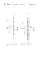
- FIG. 3is a partial autocorrelation function of a double concatenated eleventh order Barker-based code that has been one-bit delayed with respect to the autocorrelation function of FIG. 2 .
- FIG. 4is a sum discriminator function derived from summing of the autocorrelation functions of FIGS. 2 and 3.
- FIG. 5is a difference discriminator function derived from subtraction of the autocorrelation function of FIG. 2 from the autocorrelation function of FIG. 3 .
- FIGS. 6-13are illustrations of the sum and difference discriminator functions of FIGS. 4 and 5 as a target moves from outside of a semi-perimeter defined by the proximity detector to inside of the semi-perimeter.
- FIG. 14is a block diagram of the components of the proximity detector in accordance with the present invention.
- FIG. 15is an illustration of the effect of a start-up transient on a received waveform that does not include a leader segment.
- FIG. 16is a transmitted optical signal having a leader segment in accordance with a first embodiment of the invention.
- FIG. 17is a transmitted optical signal having a leader segment in accordance with a second embodiment of the invention.
- FIG. 18is an illustration of the effect of a start-up transient on a received optical signal of FIGS. 16 and 17.
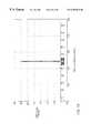
- FIGS. 19-26are illustrations showing results of simulations under various conditions.
- FIG. 27is a flow diagram of a method of detecting and ranging objects in accordance with the present invention.
- an automobile 10 embodying a number of proximity detectors 12 , 14 , 16 and 18 in accordance with one application of the inventionis shown.
- the proximity detectors 12 - 18can be incorporated into a variety of safety systems that can alert of, prepare for and/or prevent impending collisions with moving or stationary targets, such as other vehicles on the road.
- the proximity detectors 12 - 18are designed to detect targets that breach a particular virtual semi-perimeter established by one of more of the proximity detectors in order to take appropriate pre-collision measures.
- the proximity detectors 12 and 14concurrently operate to establish a virtual semi-perimeter 20 , while the proximity detectors 16 and 18 individually operate to establish virtual semi-perimeters 22 and 24 , respectively.
- the virtual semi-perimeter 20is established by optical paths 26 , 28 , 30 and 32 that extend from the proximity detector 12 and optical paths 34 , 36 and 38 that extend from the proximity detector 14 .
- the virtual semi-perimeter 22is established by optical paths 40 , 42 , 44 and 46 that extend from the proximity detector 16
- the virtual semi-perimeter 24is established by optical paths 48 , 50 and 52 that extend from the proximity detector 18 .
- Each of the optical paths 26 - 52includes a boundary zone 54 that defines a segment of the virtual semi-perimeters 20 , 22 and 24 .
- the boundary zones 54 that are associated with a particular semi-perimeter 20 , 22 and 24define that particular semi-perimeter.
- the boundary zones 54 of the optical paths 26 - 38define the virtual semi-perimeter 20 .
- the boundary zones 54 of the optical paths 40 - 46define the virtual semi-perimeter 22 , while the boundary zones 54 of the optical paths 48 - 52 define the virtual semi-perimeter 24 .
- the number of optical paths that are associated with the proximity detectors 12 - 18is not critical to the invention. However, each proximity detector 12 - 18 should utilize a sufficient number of optical paths such that a target cannot enter or leave the virtual semi-perimeters 20 - 24 without crossing one of the boundary zones 54 of the optical paths.
- a pre-collision side impact detection systemmay include the proximity detectors 12 and 14 to deploy or partially deploy side air bags to effectively protect persons riding in the automobile 10 in anticipation of a side impact collision, upon detection of a breach detection across the virtual semi-perimeter 20 by a fast moving target toward the automobile 10 .
- a back-up sensing systemmay include the proximity detector 16 to alert the driver of the automobile 10 of the close proximity of the automobile 10 to a stationary target during a reverse parking maneuver, upon detection of a breach across the virtual semi-perimeter 22 .
- a car separation systemmay include the proximity detector 18 to maintain a predetermined distance between the automobile 10 and a vehicle in front by utilizing the detection of a breach across the virtual semi-perimeter 24 by the front vehicle.
- Other applications of the proximity detectors 12 - 18are contemplated.
- the proximity detector 12may be utilized in a blind spot detection system.
- the proximity detector 12can be designed to detect a target that breach a portion of the virtual semi-perimeter 20 in a blind spot area 56 to prevent the driver of the automobile 10 from inadvertently, due to lack of visual assessment, colliding with the target when switching lanes.
- the automobile 10may include additional proximity detectors to increase the virtual semi-perimeters 20 - 24 and/or to incorporate supplementary safety systems in the automobile 10 .
- the automobile 10may additionally include two proximity detectors located on the right side of the automobile. These additional proximity detectors may establish a virtual semi-perimeter around the right side of the automobile to provide a pre-collision detection of an impending right side impact.
- the proximity detectors 12 - 18are identical devices which perform a common detecting function. Consequently, the breach detecting operation performed by the proximity detectors 12 - 18 are identically executed. Therefore, the components of the proximity detector 16 and the breach detecting operation performed by the proximity detector 16 will be described as an exemplary illustration of the proximity detectors 12 - 18 .
- the detection of the breach by the proximity detector 16is accomplished by sequentially emitting pulses of light in the optical paths 40 - 46 and analyzing received signals.
- Each of the optical paths 40 - 46is associated with an optical emitter (not shown), such as a high frequency modulated light emitting diode or a laser diode, and a photodiode (not shown).
- the optical emitterstransmit the pulses of light along the optical paths 40 - 46 , while the photodiodes receive optical signals, including reflected signals of the transmitted pulses.
- a received optical signalis determined to be an echo signal of the emitted light pulse from a target within one of the boundary zones 54 of the optical paths 40 - 46 , a breach of the semi-perimeter 22 is presumed.
- the proximity detector 16is able to discriminate the direction of the target. Since the proximity detector 16 only monitors for echo signals from one of the boundary zones 54 , rather than a large portion of the optical paths 40 - 46 , the complexity of the proximity detector 16 is significantly reduced.
- the proximity detector 16employs a pulse compression technique with binary phase modulation to determine whether a received optical signal is an echo signal from a target within the boundary zones 54 of the optical paths 40 - 46 .
- the pulses of light that are transmitted from the optical emittersare modulated in accordance with a selected binary sequence code.
- the selected codehas an autocorrelation function having negative sidelobe, as shown in FIG. 2 .
- the selected codeshould exhibit minimal sidelobe behavior that has equal ripple characteristics.
- the binary sequence code utilized by the proximity detector 16is a double concatenated eleventh order Barker-based code (hereinafter the “preferred code”) having 121 elements.
- An eleventh order Barker codeis “11100010010”.
- the preferred codeis formed by replacing a “1” of the eleventh order Barker code with another eleventh order Barker code and replacing a “0” with an inverted eleventh order Barker code to form a 121-element code.
- the proximity detector 16utilizes characteristics of two discriminator functions to determine if a target is within one of the boundary zones 54 of the optical paths 40 - 46 .
- two discriminator functionsare derived by either adding or subtracting the autocorrelation function with a one-bit delayed version of the autocorrelation function. The derivation of the two discriminator functions will be described with reference to FIGS. 2-5.
- a partial autocorrelation function 58 of the preferred codeis illustrated.
- the autocorrelation function 58is plotted with respect to relative amplitude (RA) over time (t).
- the sidelobes of the autocorrelation function 58have negative RA values.
- a partial autocorrelation function 62is shown.
- the autocorrelation function 62is a one-bit delayed version of the autocorrelation function 58 . Except for the one-bit delay, the autocorrelation function 62 is identical to the autocorrelation function 58 .
- the central peak 60 and the sidelobeshave been shifted one time increment to the right.
- the first discriminator functionis derived by adding the autocorrelation function 58 and the autocorrelation function 62 .
- the result of the summing of the two autocorrelation functions 58 and 62is a sum discriminator function 64 , shown in FIG. 4 .
- the second discriminator functionis derived by subtracting the autocorrelation function 60 from the autocorrelation function 58 .
- a difference discriminator function 68is shown.
- the difference discriminator function 68is the result of the subtraction of the autocorrelation functions 58 and 60 .
- the difference discriminator function 68also includes a number of sidelobes. The peaks of these sidelobes have positive RA values.
- the proximity detector 16is able to utilize the characteristics of the sum and difference discriminator functions 64 and 68 to determine whether a target has crossed one of the boundary zones 54 of the optical paths 40 - 46 .
- the proximity detector 16generates a sum signal that represents a point on the sum discriminator function 64 .
- the proximity detector 16generates a difference signal that represents a corresponding point on the difference discriminator function 68 .
- the pointsrepresent the distance between the proximity detector 16 and the intersection of the semi-perimeter 22 in one of the optical paths 40 - 46 .
- the components of the proximity detector 16 that generate the sum and difference signalswill be described below.
- the optical path 40is chosen to describe the detection of a target within the boundary zones 54 of the optical paths 40 - 46 .
- the sum and difference discriminator functions 64 and 68will shift along the t axis.
- the shapes of the functions 64 and 68will remain the same.
- the discriminator functions 64 and 68will move to the left. Conversely, when the target moves away from the proximity detector 16 , the discriminator functions 64 and 68 will move to the right.
- the discriminator functions 64 and 68are plotted as relative amplitude (RA) over distance (d).
- the targetis further away from the proximity detector 16 than the boundary zone 54 of the optical path 40 .
- the sum peak 66 of the discriminator function 64 and the major positive peak 70 of the discriminator function 68are to the right of the critical region on the d axis.
- the sum signal 74is negative, while the difference signal 76 is positive. Since the sum discriminator function 64 is negative outside the sum peak 66 , the sum signal 74 can be utilized to mask the fluctuating difference signal 76 due to sidelobes of the difference discriminator function 68 . Therefore, as long as the sum signal 74 is negative, the target can be assumed to be outside the boundary zone 54 of the optical path 40 .
- the sum signal 74 and the difference signal 76jump to high positive RA values, as shown in FIGS. 8 and 9.
- the sum signal 74remains positive, while the difference signal 76 dives to a large negative RA value, as shown in FIGS. 10 and 11.
- This change in the difference signal 76indicates that the target is approaching the proximity detector 16 .
- the sum signal 74returns to a negative RA value which masks the difference signal 76 , indicating that the target is not within the boundary zone 54 of the optical path 40 , as shown in FIGS. 12 and 13.
- the RA values of the sum and difference signals 74 and 76change in the opposite manner as when the target was approaching the proximity detector.
- the sum signal 74is negative, indicating that the target is not within the boundary zone 54 of the optical path 40 .
- the RA value of the sum signal 74jumps to a large positive value.
- the RA value of the difference signal 76dives to a large negative value.
- the difference signal 76inverts from a negative signal to a positive signal.
- the difference signal 76 changes from a positive signal to a negative signal while the sum signal 74 remains positivethis is an indication that the target is crossing the boundary zone 54 of the optical path 40 as the target is approaching the proximity detector 16 .
- the proximity detector 16is able to detect a target that enters the boundary zone 54 of the optical path 40 and to determine the moving direction of the target by using the characteristics of the two discriminator functions 64 and 68 .
- the proximity detector 16includes transmitter circuitry 78 , receiver circuitry 80 , a transmit/receive processor 82 and a microcontroller 84 .
- the transmitter circuitry 78contains a number of light emitters 86 , a power supply 88 and a transmit driver 90 .
- the light emitters 86may be laser diodes or high frequency modulated light emitting diodes (LEDs). The exact number of light emitters 86 is not critical to the invention.
- the transmit driver 90operates to select a light emitter 86 in response to a selected signal from the microcontroller 84 and to active the selected light emitter in accordance with a coded transmit signal from the transmit/receive processor 82 .
- the selected light emitter 86transmits an optical signal containing the coded transmit signal that will be utilized by the proximity detector 16 to detect and range a target.
- the receiver circuitry 80contains a number of photodiodes 92 , a photodiode selector 94 and a preamp 96 .
- the number of photodiodes 92should correspond to the number of light emitters 86 in which each photodiode 92 is operatively associated with a unique light emitter 86 .
- the photodiode selector 94operates to select an associated photodiode 92 in response to the select signal from the microcontroller 84 .
- the selected photodiode 92converts any received light signal into electrical current.
- the received light signalmay include a reflected version of the transmitted optical signal from the selected light emitter 86 .
- the photodiode-generated currenttravels to the transmit/receive processor 82 via the preamp 96 .
- the preamp 96transforms the small signal current from the selected photodiode 92 into a highly amplified voltage signal.
- the expected current-to-voltage gain (transimpedance)ranges from ten to twenty thousand, depending on the specifications of the photodiode 92 and preamp 96 .
- the transmit/receive processor 82includes a bandpass filter 98 and a limiting amplifier 100 that are connected in series to shape the amplified signal from the preamp 96 of the receiver circuitry 80 .
- the output of the limiting amplifier 100is connected to a pair of mixers 102 and 104 .
- the mixers 102 and 104are also connected to a receiver correlation sequence (RCS) generator 106 that provides delayed versions of the transmitted code, i.e., the preferred code.
- the preferred codeis stored in a read-only memory (not shown) within the RCS generator 106 .
- the mixer 104is configured to receive the transmitted code from the RCS generator 106 that is further delayed by a one-bit period as compared to the delayed transmitted code received by the mixer 102 .
- These two delayed codesare needed to generate signals that correspond to two different autocorrelation functions, similar to the functions 58 and 60 in FIGS. 2 and 3.
- the two delayed codesare transmitted to the mixers 102 and 104 as signals. These code signals are received by the mixers 102 and 104 and then multiplied by the output signal of the limiting amplifier 100 .
- the two multiplied signals from the mixers 102 and 104are transmitted to correlation filters 108 and 110 , respectively.
- the correlation filters 108 and 110integrate the multiplied signals from the mixers 102 and 104 .
- both integrated signals from the filters 108 and 110are relayed to a subtracting device 112 and a summing device 114 .
- the subtracting device 112determines the difference between the signal from the filter 108 and the signal from the filter 110 , while the summing device 114 determines the sum of the two signals.
- the subtracting device 112outputs a difference signal to an input of a comparator 116 .
- the comparator 116also receives a filtered difference signal from a low pass filter 118 .
- the low pass filter 118receives the difference signal from the subtracting device 112 and outputs the filtered signal to the comparator 116 .
- the filtered difference signalincludes low frequency noise caused by the mixers 102 and 104 during the multiplying operations.
- the summing device 114outputs a summed signal to a comparator 120 and a low pass filter 122 .
- the low pass filter 122filters the summed signal and provides a filtered summed signal to the comparator 120 .
- the comparators 116 and 120eliminate the low frequency noise by subtracting the noise from the summed and difference signals.
- the comparators 116 and 120then transmit the difference and summed signals that have been noise-compensated to a latch/average unit 124 .
- the latch/average unit 124receives the difference and summed signals and subsequent difference and summed signals from the following transmitted optical signals. These signals are then averaged by the latch/average unit 124 for a prescribed period.
- the averaged difference and summed signalsare sampled by the microcontroller 84 at the end of the prescribed period.
- the microcontroller 84is able to detect a target within one of the boundary zones 54 of the optical paths 40 - 46 .
- the low pass filter 118 and the comparator 116are replaced by a first analog-to-digital (A/D) converter and the low pass filter 122 and the comparator 120 are replaced by a second A/D converter.
- the A/D convertersare able to capture the strength of the summed and difference signals to provide additional information for processing by the microcontroller 84 .
- the microcontroller 84may utilize the strength of the signals to accurately determine the location of the detected target within the boundary zone.
- the transmit/receive processor 82also includes a transmit correlation sequence (TCS) generator 126 that is coupled to a master clock 128 and a state controller 130 that is coupled to the microcontroller 84 .
- TCStransmit correlation sequence
- the TCS generator 126provides either the preferred code, i.e., the double concatenated eleventh order Baker code, or an inverted version of the preferred code to the transmit driver 90 of the transmitter circuitry 78 in order to modulate the transmitting optical signal.
- the TCS generator 126includes a read-only memory (not shown) that is programmed with the preferred code.
- the master clock 128provides a clock signal to synchronize the transmission of the optical signal and the correlation process.
- the clock signalis utilized by the TCS generator 126 to transmit the normal or inverted preferred code to the transmit driver 90 .
- the RCS generator 106utilizes the clock signal to transmit delayed versions of the transmitted code to the mixers 102 and 104 .
- the time delay adjustment between the transmit and receive correlation sequencescan be accomplished by a programmable phase shifter to provide time delay adjustment over a single clock cycle and a delay counter to allow time adjustment over multiple cycles of the master clock.
- the delay of transmitted signals from the RCS generator 122 to the mixers 102 and 104are controlled by the microcontroller 84 to track a detected target by effectively varying a boundary zone within an optical path of the transmitted optical signal.
- the boundary zoneis moved further away from the proximity detector 16 , if the microcontroller 84 determines that the detected target is moving away from the detector 16 . Conversely, the boundary zone is moved closer to the proximity detector 16 , if the detected target is approaching the proximity detector 16 .
- the state controller 130operates to invert the transmitted signals from the TCS generator 126 and from the RCS generator 106 , as well as the summed and difference signals received by the latch/average unit 124 .
- the inversion of the signalsis desired to offset noise generated by the mixer 102 and 104 .
- the state controller 130is designed to activate the transmit driver 90 of the transmitter circuitry 78 to attach a leader segment to each optical signal generated by one of the light emitters 86 .
- the transmitted signalsare typically modulated using orthogonal two phase coding which multiplies the bipolar correlation codes by a higher frequency sinusoid. Typically, this modulation is at least twice the fundamental frequency of the code sequence.
- Thishas an advantage in radar systems, since the signal spectrum must be narrowed and moved away from DC to allow transmission.
- the bipolar wave shapecan be transmitted as long as coherent detection is performed.
- an optical radar systemsuch as the proximity detector 16
- using incoherent modulation and detectiononly uni-polar information can be transmitted.
- the approach of the proximity detector 16is to transmit the digital code, i.e., the transmitted optical signal, at baseband instead of up-converting the signal. This allows the reduction of LED and receiver bandwidth requirements.
- the low frequency cut-offmust be close to DC to minimize bias level shift during the convolution bit sequence. Based on the use of the eleventh order barker code with a bit period of approximately 30 nanoseconds, a low frequency cut-off of 200 Khz is necessary to maintain good pulse shape throughout the burst. Unfortunately, the low frequency cutoff also produces a significant start-up error in the waveform bias level, as shown in FIG. 15 .
- a start-up transient in a received waveform 132is shown. Since the portion of the waveform 132 that is affected contains a segment of the code sequence, the correlation of the received waveform 132 to a reference signal will be affected. To reduce the effect of the starting transient, the transmitter circuitry 110 operate to transmit an unmodulated half-amplitude signal in front of the modulated waveform, i.e., the preferred code, to establish a zero amplitude reference prior to the burst transmission.
- the unmodulated half-amplitude signalwill be referred to as the “leader segment.”
- a transmitted optical signal 134 having a leader segment 136 in accordance with a first embodimentis shown.
- the optical signal 134also includes a code sequence 138 that embodies the preferred code.
- the leader segment 136is a constant half-powered optical signal.
- another transmitted optical signal 140 having a leader segment 142 and the code sequence 138 in accordance with a second embodimentis shown.
- the leader segment 142is a series of full-powered optical pulses separated by spaces to yield an average power equal to half of the full-powered optical pulses to establish the amplitude reference.
- the required length of the leader segments 136 and 142is dependent on the low frequency cut-off of the bandpass filter 98 .
- FIG. 18shows a received optical signal 144 , i.e., one of the optical signals 134 and 140 .
- the code sequence 138 of the received optical signal 144is hardly affected by the start-up transient.
- the leader segments 136 and 142is able to reduce the effects of the start-up transient on the code sequence 138 .
- the microcontroller 84sends a select signal to the transmit driver 90 and the photodiode selector 94 to select a particular light emitter 86 and an associated photodiode 92 .
- the microcontrolleralso sends a start signal to the state controller 126 .
- the state controller 126transmits a control signal to the transmit driver 90 to send the leader segment of an optical signal.
- the transmit driver 90activates the selected light emitter 86 to optically send the leader segment.
- the TCS generator 126transmits the preferred code to the transmit driver 90 in response to the state controller 130 .
- the state controller 130will determine whether the preferred code is to be inverted prior to transmission of the preferred code to the transmit driver 90 . Assuming that the current cycle calls for a non-inverted, preferred code, the selected light emitter 86 is driven by the transmit driver 90 to optically transmit the preferred code.
- the optical signal from the selected light emitter 86propagates in a predetermined optical path away from the proximity detector 16 .
- the optical signalimpinges upon a target and is reflected back to the proximity detector 16 .
- the reflected optical signalalong with any optical noise is received by the associated photodiode 92 .
- the photodiode 92generates current in response to the received optical signal.
- the generated currentis then amplified by the preamp 96 and transmitted to the bandpass filter 98 of the transmit/receive processor 82 .
- the leader segment of the optical signalcauses a start-up transient. After the start-up transient, the zero amplitude reference is established.
- the coded segment of the optical signalis filtered by the bandpass filter 98 and then amplified by the limiting amplifier 100 .
- the filtered and amplified coded signalis inputted into the mixers 102 and 104 .
- the coded signalsare multiplied by delayed versions of the transmitted code that are provide by the RCS generator 106 .
- the RCS generator 106utilizes the clock signal from the master clock 128 to provide the delayed versions of the preferred code.
- the delayed code to the mixer 104is further delayed by a one-bit period as compared to the delay code to the mixer 102 .
- the mixers 102 and 104transmit multiplied signals to the correlation filters 108 and 110 , respectively, where the multiplied signals are integrated.
- the integrated signals from the correlation filters 108 and 110are then relayed to the subtracting device 112 and the summing device 114 .
- the two integrated signalsare summed by the summing device 114 , while the integrated signal from the correlation filter 108 is subtracted by the integrated signal from the correlation filter 110 by the subtracting device 112 .
- the summed signalis then transmitted to the low pass filter 122 and the comparator 120 , where the noise in the summed signal is reduced.
- the difference signalis transmitted to the low pass filter 118 and the comparator 116 , where the noise in the difference signal is also reduced.
- the noise-reduced summed and difference signalsare outputted to the latch/average unit 124 , completing one correlation process within a series of correlations.
- the state controller 130operates to invert the transmitted signal from the TCS generator 126 to the transmit driver.
- the delayed code transmitted from the RCS generator 106 to the mixers 102 and 104is inverted.
- the summed and difference signals from the comparators 116 and 120are inverted within the latch/average unit 124 .
- the state controller 130ensures that the transmitted signals from the TCS and RCS generators 126 and 106 and the summed and difference signals received by the latch/average unit 124 are again inverted.
- the correlation processesare performed in this alternating fashion until a sufficient amount of summed and difference signals are captured and averaged by the latch/average unit 124 , completing a single sampling period.
- the averaged difference and summed signalsare sampled by the microcontroller 84 at the end of this single sampling period.
- thirty correlation processesmay be performed during the single sampling period. Similar correlation processes are then repeated for each pair of light emitter 86 and photodiode 92 to detect any targets within other boundary zones being monitored by the proximity detector 16 .
- FIGS. 19-26show results of simulations under various conditions.
- FIG. 19is a superimposed result of the ideal autocorrelation functions of two double concatenated eleventh order Barker-based codes, i.e., the preferred codes, with and without a one code bit delay.
- the simulationwas made using Barker sequence without filtering and noise injection.
- This codeexhibited negative sidelobes for 13 bit cycles on either side of the central lobe as with the eleventh order sequence.
- the ratio between the autocorrelation peak and the sidelobe rippleis the same as the eleventh order case.
- FIG. 20shows the sum and difference of autocorrelation functions of FIG. 19 .
- FIG. 21shows the output of the receiver bandpass filter for the double concatenated eleventh order Barker sequence with a half value leader segment added.
- the transmit correlation sequenceis lowpass filtered with a 20 MHz cut-off frequency to simulate the effect of the LED's bandwidth limitation.
- the signalis bandpass filtered with a passband from 200 kHz to 50 MHz. No noise has been added.
- the leader segmentis sufficiently long to allow the decay of the leading transient response before the start of the correlation sequence.
- FIG. 22shows a superimposed result of the autocorrelation sequences in FIG. 19 with and without a 1 code bit delay.
- the simulationwas made using Barker sequences with filtering and without noise injection. This code exhibited a higher degree of sidelobe distortion near the central peak than in the ideal case.
- FIG. 23shows the sum and difference of autocorrelation functions of FIG. 22 .
- FIG. 24shows an autocorrelation channel difference signal over a range of delay values sufficient to observe the central discriminator function.
- the correlation sequenceconsisted of the double concatenated eleventh order Barker sequence.
- the received signal carrier-to-noise rationis 0.1:1, with the plot superimposing ten data set results.
- the relative response zero crossinghas an envelope representing the peak-to-peak ranging uncertainty.
- FIG. 25compares the difference signal transfer function using summed zero crossing thresholds with digital value signal integration at a low carrier-to-noise ratio of 0.1:1.
- the result of an analog integrationis shown as function 126 .
- the result of a digital integrationis shown as function 128 .
- the transfer function of the zero-crossing processingis very close to the performance of the ideal signal integration.
- the expected signal processing degradation due to digital zero-crossing processingis only 1-2 dB.
- FIG. 26shows the effect on the difference signal transfer function of signal crosstalk at zero range delay. In this case the crosstalk is five times the received signal.
- the masking of the sum signal channelcauses the edge of the central transfer function to collapse toward zero delay as interference increase.
- a leader segmentis transmitted by a transmitter of the proximity detector.
- the leader segmentis an optical signal that is utilized by the proximity detector to establish an amplitude reference, when the leader segment is reflected from a target and received by the proximity detector.
- the leader segmentmay be a constant half-powered optical signal.
- the leader segmentmay be a series of full-powered pulses separated by enough space to yield an average power equal to half power.
- an optical transmission signalthat has been modulated in accordance with the preferred code, i.e., the double concatenated eleventh order Barker-based code, is transmitted by the transmitter.
- a return signalis received by a receiver of the proximity detector at step 154 .
- the return signalmay include a portion of the leader segment and transmission signal that have been reflected from a target at a particular distance from the proximity detector.
- the proximity detectorcross-correlates the return signal with two delayed versions of the preferred code at step 156 .
- the first delayed codeis time-delayed to correspond to the particular distance from the proximity detector.
- the second delayed codeis further time-delayed by a one-bit period with respect to the first delayed code. Using the delayed codes, first and second autocorrelation signals are produced.
- the first autocorrelation signalis produced by correlating the return signal with the first delayed signal, while the second autocorrelation signals are produced by correlating the return signal with the second delayed signal.
- the first and second autocorrelation signalsare summed by the proximity detector to derive a summed signal.
- the second autocorrelation signalis subtracted from the first autocorrelation signal to derive a difference signal.
- steps 158 and 160are performed in a parallel manner.
- the summed and difference signalsare processed by a microcontroller of the proximity detector to determine whether a target is present at the particular distance from the proximity detector.
- the proximity detectormay be included in a safety system for other pre-collision detections, such as pre-collision detection during a back-up of an automobile.
- the proximity detectormay be installed in a security system on a premises to detect unauthorized intrusion within a set perimeter around the premises.
- the proximity detectormay be utilized for robotic vision.
- the proximity detectorcan be implemented in any number of systems in which detection and/or tracking of objects are/is desired.
Landscapes
- Physics & Mathematics (AREA)
- Engineering & Computer Science (AREA)
- Electromagnetism (AREA)
- Computer Networks & Wireless Communication (AREA)
- General Physics & Mathematics (AREA)
- Radar, Positioning & Navigation (AREA)
- Remote Sensing (AREA)
- Optical Radar Systems And Details Thereof (AREA)
Abstract
Description
Claims (20)
Priority Applications (3)
| Application Number | Priority Date | Filing Date | Title |
|---|---|---|---|
| US09/252,361US6307622B1 (en) | 1999-02-17 | 1999-02-17 | Correlation based optical ranging and proximity detector |
| DE60027066TDE60027066T2 (en) | 1999-02-17 | 2000-01-22 | Correlation based optical rangefinder and proximity sensor |
| EP00101323AEP1030192B1 (en) | 1999-02-17 | 2000-01-22 | Correlation based optical ranging and proximity detector |
Applications Claiming Priority (1)
| Application Number | Priority Date | Filing Date | Title |
|---|---|---|---|
| US09/252,361US6307622B1 (en) | 1999-02-17 | 1999-02-17 | Correlation based optical ranging and proximity detector |
Publications (1)
| Publication Number | Publication Date |
|---|---|
| US6307622B1true US6307622B1 (en) | 2001-10-23 |
Family
ID=22955702
Family Applications (1)
| Application Number | Title | Priority Date | Filing Date |
|---|---|---|---|
| US09/252,361Expired - LifetimeUS6307622B1 (en) | 1999-02-17 | 1999-02-17 | Correlation based optical ranging and proximity detector |
Country Status (3)
| Country | Link |
|---|---|
| US (1) | US6307622B1 (en) |
| EP (1) | EP1030192B1 (en) |
| DE (1) | DE60027066T2 (en) |
Cited By (70)
| Publication number | Priority date | Publication date | Assignee | Title |
|---|---|---|---|---|
| US20020075178A1 (en)* | 2000-08-16 | 2002-06-20 | Woodington Walter Gordon | Radar transmitter circuitry and techniques |
| US6443400B2 (en)* | 1999-12-20 | 2002-09-03 | Shinko Electric Co., Ltd. | Automatic transport system |
| US6611227B1 (en) | 2002-08-08 | 2003-08-26 | Raytheon Company | Automotive side object detection sensor blockage detection system and related techniques |
| US20030160717A1 (en)* | 2001-03-20 | 2003-08-28 | Bernhard Mattes | Radar sensor platform |
| US6642908B2 (en) | 2000-08-16 | 2003-11-04 | Raytheon Company | Switched beam antenna architecture |
| US20030229402A1 (en)* | 2001-12-14 | 2003-12-11 | Andreas Junger | Method and device for activating and/or deactivating distributed control units |
| US6675094B2 (en) | 2000-09-08 | 2004-01-06 | Raytheon Company | Path prediction system and method |
| US6683557B2 (en) | 2000-08-16 | 2004-01-27 | Raytheon Company | Technique for changing a range gate and radar for coverage |
| US6708100B2 (en) | 2001-03-14 | 2004-03-16 | Raytheon Company | Safe distance algorithm for adaptive cruise control |
| US20040090316A1 (en)* | 2002-11-07 | 2004-05-13 | Shih-Hsiung Li | Method and apparatus for reducing blind sptos in obstacle detection |
| US6748312B2 (en) | 2000-08-16 | 2004-06-08 | Raytheon Company | Safe distance algorithm for adaptive cruise control |
| US6784828B2 (en) | 2000-08-16 | 2004-08-31 | Raytheon Company | Near object detection system |
| US20040169840A1 (en)* | 2002-11-28 | 2004-09-02 | Yoshiaki Hoashi | Vehicle radar device |
| US20040178952A1 (en)* | 2003-03-11 | 2004-09-16 | M/A Com, Inc. | Adding error correction and coding to a radar system |
| US20040233414A1 (en)* | 2003-05-19 | 2004-11-25 | Jamieson James R. | Laser perimeter awareness system |
| US6903679B2 (en) | 2000-08-16 | 2005-06-07 | Raytheon Company | Video amplifier for a radar receiver |
| US6970142B1 (en) | 2001-08-16 | 2005-11-29 | Raytheon Company | Antenna configurations for reduced radar complexity |
| US20060002485A1 (en)* | 2004-07-01 | 2006-01-05 | Icefyre Semiconductor Corporation | Systems and methods for rapid signal detection and identification |
| US6995730B2 (en) | 2001-08-16 | 2006-02-07 | Raytheon Company | Antenna configurations for reduced radar complexity |
| US20060072099A1 (en)* | 2004-10-01 | 2006-04-06 | Denso Corporation | Vehicular radar system |
| US20060221662A1 (en)* | 2005-03-16 | 2006-10-05 | Samsung Electronics Co., Ltd. | Display device and driving method thereof |
| US7183995B2 (en) | 2001-08-16 | 2007-02-27 | Raytheon Company | Antenna configurations for reduced radar complexity |
| US20070146684A1 (en)* | 2004-10-01 | 2007-06-28 | Denso Corporation | Vehicular radar system |
| US7243013B2 (en) | 2002-11-13 | 2007-07-10 | Ford Global Technologies, Llc | Vehicle radar-based side impact assessment method |
| US20090201489A1 (en)* | 2004-07-30 | 2009-08-13 | Avalon Innovation Ab | Monitoring device |
| US20100097216A1 (en)* | 2006-11-14 | 2010-04-22 | Christopher John Morcom | Intruder detection system |
| US20110018698A1 (en)* | 2009-07-27 | 2011-01-27 | Charlton Rodriguez | Electrical car sensor for blind spots |
| US7973701B2 (en) | 2008-03-31 | 2011-07-05 | Valeo Radar Systems, Inc. | Automotive radar sensor blockage detection system and related techniques |
| US20120176596A1 (en)* | 2006-01-24 | 2012-07-12 | Gerd Reime | Method for measuring the propagation time of light |
| US20130004157A1 (en)* | 2011-06-29 | 2013-01-03 | Christophe Jean Erez Hakim | Optical detector |
| US20130056622A1 (en)* | 2010-04-02 | 2013-03-07 | Centre Nationla De La Recherch Scientifique (C.N.R.S.) | Analog electronic circuit for processing a light signal, and corresponding processing system and method |
| DE102004059994B4 (en)* | 2003-12-17 | 2014-07-10 | Denso Corporation | Device for detecting a body |
| US20140290284A1 (en)* | 2013-04-01 | 2014-10-02 | Spinnaker Process Instruments | Proximity detection in networked freezer stocking management |
| US8994925B2 (en) | 2012-03-27 | 2015-03-31 | Pulsedlight, Inc. | Optical distance measurement device |
| JP2015135273A (en)* | 2014-01-17 | 2015-07-27 | オムロンオートモーティブエレクトロニクス株式会社 | laser radar device |
| DE102014118055A1 (en)* | 2014-12-08 | 2016-06-09 | Valeo Schalter Und Sensoren Gmbh | Transmitting device, receiving device and object detection device for a motor vehicle and method for this |
| US9829567B1 (en)* | 2016-06-20 | 2017-11-28 | Uhnder, Inc. | Power control for improved near-far performance of radar systems |
| US20170341579A1 (en)* | 2016-05-24 | 2017-11-30 | Andy Karuza | Proximity Warning Device |
| US9869762B1 (en) | 2016-09-16 | 2018-01-16 | Uhnder, Inc. | Virtual radar configuration for 2D array |
| WO2018013839A1 (en)* | 2016-07-13 | 2018-01-18 | Texas Instruments Incorporated | Method and apparatus for narrowband ranging systems |
| US9945943B2 (en) | 2016-04-07 | 2018-04-17 | Uhnder, Inc. | Adaptive transmission and interference cancellation for MIMO radar |
| US9954955B2 (en) | 2016-04-25 | 2018-04-24 | Uhnder, Inc. | Vehicle radar system with a shared radar and communication system |
| US9971020B1 (en) | 2017-02-10 | 2018-05-15 | Uhnder, Inc. | Radar data buffering |
| US9989638B2 (en) | 2016-04-25 | 2018-06-05 | Uhnder, Inc. | Adaptive filtering for FMCW interference mitigation in PMCW radar systems |
| US9989627B2 (en) | 2016-04-25 | 2018-06-05 | Uhnder, Inc. | Vehicular radar system with self-interference cancellation |
| US10142133B2 (en) | 2016-04-25 | 2018-11-27 | Uhnder, Inc. | Successive signal interference mitigation |
| US10145954B2 (en) | 2016-04-07 | 2018-12-04 | Uhnder, Inc. | Software defined automotive radar systems |
| US10191142B2 (en) | 2016-04-25 | 2019-01-29 | Uhnder, Inc. | Digital frequency modulated continuous wave radar using handcrafted constant envelope modulation |
| US10261179B2 (en) | 2016-04-07 | 2019-04-16 | Uhnder, Inc. | Software defined automotive radar |
| US10324165B2 (en) | 2016-04-25 | 2019-06-18 | Uhnder, Inc. | PMCW—PMCW interference mitigation |
| US10573959B2 (en) | 2016-04-25 | 2020-02-25 | Uhnder, Inc. | Vehicle radar system using shaped antenna patterns |
| US10908272B2 (en) | 2017-02-10 | 2021-02-02 | Uhnder, Inc. | Reduced complexity FFT-based correlation for automotive radar |
| US10969477B2 (en)* | 2015-10-01 | 2021-04-06 | Datalogic Ip Tech S.R.L. | Method to detect a signal and optoelectronic sensor |
| US11027927B2 (en)* | 2019-01-10 | 2021-06-08 | Daifuku Co., Ltd. | Article conveyance apparatus |
| US11105890B2 (en) | 2017-12-14 | 2021-08-31 | Uhnder, Inc. | Frequency modulated signal cancellation in variable power mode for radar applications |
| US11346941B2 (en)* | 2019-03-26 | 2022-05-31 | Texas Instruments Incorporated | Shaped ultrasonic transmission and echo processing with coding |
| US11454697B2 (en) | 2017-02-10 | 2022-09-27 | Uhnder, Inc. | Increasing performance of a receive pipeline of a radar with memory optimization |
| US11474225B2 (en) | 2018-11-09 | 2022-10-18 | Uhnder, Inc. | Pulse digital mimo radar system |
| US11545013B2 (en)* | 2016-10-26 | 2023-01-03 | A9.Com, Inc. | Customizable intrusion zones for audio/video recording and communication devices |
| JPWO2023007597A1 (en)* | 2021-07-28 | 2023-02-02 | ||
| US11635043B2 (en) | 2011-06-08 | 2023-04-25 | Raytheon Technologies Corporation | Geared architecture for high speed and small volume fan drive turbine |
| US11681017B2 (en) | 2019-03-12 | 2023-06-20 | Uhnder, Inc. | Method and apparatus for mitigation of low frequency noise in radar systems |
| US11698007B2 (en) | 2011-06-08 | 2023-07-11 | Raytheon Technologies Corporation | Flexible support structure for a geared architecture gas turbine engine |
| US11899126B2 (en) | 2020-01-13 | 2024-02-13 | Uhnder, Inc. | Method and system for multi-chip operation of radar systems |
| US11970984B2 (en) | 2012-04-02 | 2024-04-30 | Rtx Corporation | Gas turbine engine with power density range |
| FR3144308A1 (en)* | 2022-12-23 | 2024-06-28 | Valeo Vision | Optical system for a vehicle comprising means for emitting a coded light signal at very high frequency |
| US12096156B2 (en) | 2016-10-26 | 2024-09-17 | Amazon Technologies, Inc. | Customizable intrusion zones associated with security systems |
| US12163582B2 (en) | 2011-06-08 | 2024-12-10 | Rtx Corporation | Flexible support structure for a geared architecture gas turbine engine |
| US12366179B2 (en) | 2012-01-31 | 2025-07-22 | Rtx Corporation | Gas turbine engine with high speed low pressure turbine section and bearing support features |
| US12386029B2 (en) | 2018-01-29 | 2025-08-12 | Robert Bosch Gmbh | Millimeter wave automotive radar systems |
Families Citing this family (3)
| Publication number | Priority date | Publication date | Assignee | Title |
|---|---|---|---|---|
| GB2420238B (en)* | 2004-11-04 | 2007-03-21 | Instro Prec Ltd | Correlation apparatus and method |
| CN104931975B (en)* | 2015-06-17 | 2017-08-22 | 浙江理工大学 | Phase code laser imaging radar based on microwave photon signal transacting |
| CN116087918A (en)* | 2022-12-21 | 2023-05-09 | 武汉万集光电技术有限公司 | A distance measuring method, device, terminal equipment and computer-readable storage medium |
Citations (5)
| Publication number | Priority date | Publication date | Assignee | Title |
|---|---|---|---|---|
| US5141308A (en) | 1991-08-12 | 1992-08-25 | Danckwerth Thomas M | Semiconductor laser pulse compression radar system |
| US5189428A (en) | 1990-12-27 | 1993-02-23 | Thomson-Csf | Method for the processing of a digitally encoded pulse signal |
| US5417114A (en) | 1989-02-28 | 1995-05-23 | Mitsubishi Denki Kabushiki Kaisha | Echo based detecting apparatus employing signal generator and correlator |
| US5786788A (en)* | 1996-10-08 | 1998-07-28 | Raytheon Company | Radar system and method for reducing range sidelobes |
| US5903597A (en)* | 1996-05-20 | 1999-05-11 | Trimble Navigation Limited | Suppression on multipath signal effects |
Family Cites Families (5)
| Publication number | Priority date | Publication date | Assignee | Title |
|---|---|---|---|---|
| US3802780A (en)* | 1972-06-12 | 1974-04-09 | Us Army | Optical device for position location |
| FR2327553A1 (en)* | 1975-10-10 | 1977-05-06 | Thomson Csf | MEASUREMENT DEVICE BY ELECTRONIC CORRELATION OF THE DELAY BETWEEN TWO TIME SIGNALS AND SYSTEMS INCLUDING SUCH A DEVICE |
| CA2038818A1 (en)* | 1990-03-30 | 1991-10-01 | Akio Nagamune | Distance measuring method and apparatus therefor |
| US5077753A (en)* | 1990-04-09 | 1991-12-31 | Proxim, Inc. | Radio communication system using spread spectrum techniques |
| JP2669393B2 (en)* | 1995-04-11 | 1997-10-27 | 日本電気株式会社 | Interference wave canceller |
- 1999
- 1999-02-17USUS09/252,361patent/US6307622B1/ennot_activeExpired - Lifetime
- 2000
- 2000-01-22DEDE60027066Tpatent/DE60027066T2/ennot_activeExpired - Lifetime
- 2000-01-22EPEP00101323Apatent/EP1030192B1/ennot_activeExpired - Lifetime
Patent Citations (5)
| Publication number | Priority date | Publication date | Assignee | Title |
|---|---|---|---|---|
| US5417114A (en) | 1989-02-28 | 1995-05-23 | Mitsubishi Denki Kabushiki Kaisha | Echo based detecting apparatus employing signal generator and correlator |
| US5189428A (en) | 1990-12-27 | 1993-02-23 | Thomson-Csf | Method for the processing of a digitally encoded pulse signal |
| US5141308A (en) | 1991-08-12 | 1992-08-25 | Danckwerth Thomas M | Semiconductor laser pulse compression radar system |
| US5903597A (en)* | 1996-05-20 | 1999-05-11 | Trimble Navigation Limited | Suppression on multipath signal effects |
| US5786788A (en)* | 1996-10-08 | 1998-07-28 | Raytheon Company | Radar system and method for reducing range sidelobes |
Cited By (125)
| Publication number | Priority date | Publication date | Assignee | Title |
|---|---|---|---|---|
| US6592080B2 (en) | 1999-12-20 | 2003-07-15 | Shinko Electric Co., Ltd. | Automatic transport system |
| US6443400B2 (en)* | 1999-12-20 | 2002-09-03 | Shinko Electric Co., Ltd. | Automatic transport system |
| US7071868B2 (en) | 2000-08-16 | 2006-07-04 | Raytheon Company | Radar detection method and apparatus |
| US6784828B2 (en) | 2000-08-16 | 2004-08-31 | Raytheon Company | Near object detection system |
| US6707419B2 (en)* | 2000-08-16 | 2004-03-16 | Raytheon Company | Radar transmitter circuitry and techniques |
| US6577269B2 (en)* | 2000-08-16 | 2003-06-10 | Raytheon Company | Radar detection method and apparatus |
| US6642908B2 (en) | 2000-08-16 | 2003-11-04 | Raytheon Company | Switched beam antenna architecture |
| US6864831B2 (en) | 2000-08-16 | 2005-03-08 | Raytheon Company | Radar detection method and apparatus |
| US6977609B2 (en) | 2000-08-16 | 2005-12-20 | Raytheon Company | Technique for changing a range gate and radar coverage |
| US6683557B2 (en) | 2000-08-16 | 2004-01-27 | Raytheon Company | Technique for changing a range gate and radar for coverage |
| US6816107B2 (en) | 2000-08-16 | 2004-11-09 | Raytheon Company | Technique for changing a range gate and radar coverage |
| US20020075178A1 (en)* | 2000-08-16 | 2002-06-20 | Woodington Walter Gordon | Radar transmitter circuitry and techniques |
| US6903679B2 (en) | 2000-08-16 | 2005-06-07 | Raytheon Company | Video amplifier for a radar receiver |
| US6748312B2 (en) | 2000-08-16 | 2004-06-08 | Raytheon Company | Safe distance algorithm for adaptive cruise control |
| US6675094B2 (en) | 2000-09-08 | 2004-01-06 | Raytheon Company | Path prediction system and method |
| US6708100B2 (en) | 2001-03-14 | 2004-03-16 | Raytheon Company | Safe distance algorithm for adaptive cruise control |
| US7095361B2 (en)* | 2001-03-20 | 2006-08-22 | Robert Bosch Gmbh | Radar sensor platform |
| US20030160717A1 (en)* | 2001-03-20 | 2003-08-28 | Bernhard Mattes | Radar sensor platform |
| US7183995B2 (en) | 2001-08-16 | 2007-02-27 | Raytheon Company | Antenna configurations for reduced radar complexity |
| US6995730B2 (en) | 2001-08-16 | 2006-02-07 | Raytheon Company | Antenna configurations for reduced radar complexity |
| US6970142B1 (en) | 2001-08-16 | 2005-11-29 | Raytheon Company | Antenna configurations for reduced radar complexity |
| US20030229402A1 (en)* | 2001-12-14 | 2003-12-11 | Andreas Junger | Method and device for activating and/or deactivating distributed control units |
| US6907329B2 (en)* | 2001-12-14 | 2005-06-14 | Robert Bosch Gmbh | Method and device for activating and/or deactivating distributed control units |
| US6611227B1 (en) | 2002-08-08 | 2003-08-26 | Raytheon Company | Automotive side object detection sensor blockage detection system and related techniques |
| US20040090316A1 (en)* | 2002-11-07 | 2004-05-13 | Shih-Hsiung Li | Method and apparatus for reducing blind sptos in obstacle detection |
| US6982634B2 (en)* | 2002-11-07 | 2006-01-03 | Shih-Hsiung Li | Method and apparatus for reducing blind spots in obstacle detection |
| US7243013B2 (en) | 2002-11-13 | 2007-07-10 | Ford Global Technologies, Llc | Vehicle radar-based side impact assessment method |
| US20040169840A1 (en)* | 2002-11-28 | 2004-09-02 | Yoshiaki Hoashi | Vehicle radar device |
| US7158217B2 (en)* | 2002-11-28 | 2007-01-02 | Denso Corporation | Vehicle radar device |
| US6917327B2 (en)* | 2003-03-11 | 2005-07-12 | M/A Com, Inc. | Adding error correction and coding to a radar system |
| US20040178952A1 (en)* | 2003-03-11 | 2004-09-16 | M/A Com, Inc. | Adding error correction and coding to a radar system |
| US20040233414A1 (en)* | 2003-05-19 | 2004-11-25 | Jamieson James R. | Laser perimeter awareness system |
| US6985212B2 (en)* | 2003-05-19 | 2006-01-10 | Rosemount Aerospace Inc. | Laser perimeter awareness system |
| DE102004059994B4 (en)* | 2003-12-17 | 2014-07-10 | Denso Corporation | Device for detecting a body |
| US20080123763A1 (en)* | 2004-07-01 | 2008-05-29 | Zarbana Digital Fund Llc | Systems and methods for rapid signal detection and identification |
| US20060002485A1 (en)* | 2004-07-01 | 2006-01-05 | Icefyre Semiconductor Corporation | Systems and methods for rapid signal detection and identification |
| US7773701B2 (en) | 2004-07-01 | 2010-08-10 | Moher Michael L | Systems and methods for rapid signal detection and identification |
| US7346116B2 (en)* | 2004-07-01 | 2008-03-18 | Zarbana Digital Fund Llc | Systems and methods for rapid signal detection and identification |
| US8279414B2 (en)* | 2004-07-30 | 2012-10-02 | Avalon Innovation Ab | Monitoring device |
| US20090201489A1 (en)* | 2004-07-30 | 2009-08-13 | Avalon Innovation Ab | Monitoring device |
| US20070146684A1 (en)* | 2004-10-01 | 2007-06-28 | Denso Corporation | Vehicular radar system |
| US7242461B2 (en)* | 2004-10-01 | 2007-07-10 | Denso Corporation | Vehicular radar system |
| US7245359B1 (en)* | 2004-10-01 | 2007-07-17 | Denso Corporation | Vehicular radar system |
| US20060072099A1 (en)* | 2004-10-01 | 2006-04-06 | Denso Corporation | Vehicular radar system |
| US20060221662A1 (en)* | 2005-03-16 | 2006-10-05 | Samsung Electronics Co., Ltd. | Display device and driving method thereof |
| US7688292B2 (en) | 2005-03-16 | 2010-03-30 | Samsung Electronics Co., Ltd. | Organic light emitting diode display device and driving method thereof |
| US20120176596A1 (en)* | 2006-01-24 | 2012-07-12 | Gerd Reime | Method for measuring the propagation time of light |
| US8643827B2 (en)* | 2006-01-24 | 2014-02-04 | Mechaless Systems Gmbh | Method for measuring the propagation time of light |
| US20100097216A1 (en)* | 2006-11-14 | 2010-04-22 | Christopher John Morcom | Intruder detection system |
| US8354928B2 (en) | 2006-11-14 | 2013-01-15 | Instro Precision Limited | Intruder detection system |
| US7973701B2 (en) | 2008-03-31 | 2011-07-05 | Valeo Radar Systems, Inc. | Automotive radar sensor blockage detection system and related techniques |
| US20110018698A1 (en)* | 2009-07-27 | 2011-01-27 | Charlton Rodriguez | Electrical car sensor for blind spots |
| US20130056622A1 (en)* | 2010-04-02 | 2013-03-07 | Centre Nationla De La Recherch Scientifique (C.N.R.S.) | Analog electronic circuit for processing a light signal, and corresponding processing system and method |
| US9087223B2 (en)* | 2010-04-02 | 2015-07-21 | Centre National De La Rcherche Scientifique (C.N.R.S) | Analog electronic circuit for processing a light signal, and corresponding processing system and method |
| US11635043B2 (en) | 2011-06-08 | 2023-04-25 | Raytheon Technologies Corporation | Geared architecture for high speed and small volume fan drive turbine |
| US11698007B2 (en) | 2011-06-08 | 2023-07-11 | Raytheon Technologies Corporation | Flexible support structure for a geared architecture gas turbine engine |
| US12163582B2 (en) | 2011-06-08 | 2024-12-10 | Rtx Corporation | Flexible support structure for a geared architecture gas turbine engine |
| US20130004157A1 (en)* | 2011-06-29 | 2013-01-03 | Christophe Jean Erez Hakim | Optical detector |
| US8988660B2 (en)* | 2011-06-29 | 2015-03-24 | Silicon Laboratories Inc. | Optical detector |
| US12366179B2 (en) | 2012-01-31 | 2025-07-22 | Rtx Corporation | Gas turbine engine with high speed low pressure turbine section and bearing support features |
| US8994925B2 (en) | 2012-03-27 | 2015-03-31 | Pulsedlight, Inc. | Optical distance measurement device |
| US9581684B2 (en) | 2012-03-27 | 2017-02-28 | Garmin Switzerland Gmbh | Optical distance measurement device |
| US11970984B2 (en) | 2012-04-02 | 2024-04-30 | Rtx Corporation | Gas turbine engine with power density range |
| US20140290284A1 (en)* | 2013-04-01 | 2014-10-02 | Spinnaker Process Instruments | Proximity detection in networked freezer stocking management |
| JP2015135273A (en)* | 2014-01-17 | 2015-07-27 | オムロンオートモーティブエレクトロニクス株式会社 | laser radar device |
| DE102014118055A1 (en)* | 2014-12-08 | 2016-06-09 | Valeo Schalter Und Sensoren Gmbh | Transmitting device, receiving device and object detection device for a motor vehicle and method for this |
| US10969477B2 (en)* | 2015-10-01 | 2021-04-06 | Datalogic Ip Tech S.R.L. | Method to detect a signal and optoelectronic sensor |
| US11906620B2 (en) | 2016-04-07 | 2024-02-20 | Uhnder, Inc. | Software defined automotive radar systems |
| US11614538B2 (en) | 2016-04-07 | 2023-03-28 | Uhnder, Inc. | Software defined automotive radar |
| US11262448B2 (en) | 2016-04-07 | 2022-03-01 | Uhnder, Inc. | Software defined automotive radar |
| US10215853B2 (en) | 2016-04-07 | 2019-02-26 | Uhnder, Inc. | Adaptive transmission and interference cancellation for MIMO radar |
| US10145954B2 (en) | 2016-04-07 | 2018-12-04 | Uhnder, Inc. | Software defined automotive radar systems |
| US11086010B2 (en) | 2016-04-07 | 2021-08-10 | Uhnder, Inc. | Software defined automotive radar systems |
| US9945943B2 (en) | 2016-04-07 | 2018-04-17 | Uhnder, Inc. | Adaptive transmission and interference cancellation for MIMO radar |
| US10261179B2 (en) | 2016-04-07 | 2019-04-16 | Uhnder, Inc. | Software defined automotive radar |
| US11194016B2 (en) | 2016-04-25 | 2021-12-07 | Uhnder, Inc. | Digital frequency modulated continuous wave radar using handcrafted constant envelope modulation |
| US9989638B2 (en) | 2016-04-25 | 2018-06-05 | Uhnder, Inc. | Adaptive filtering for FMCW interference mitigation in PMCW radar systems |
| US10324165B2 (en) | 2016-04-25 | 2019-06-18 | Uhnder, Inc. | PMCW—PMCW interference mitigation |
| US10536529B2 (en) | 2016-04-25 | 2020-01-14 | Uhnder Inc. | Vehicle radar system with a shared radar and communication system |
| US10551482B2 (en) | 2016-04-25 | 2020-02-04 | Uhnder, Inc. | Vehicular radar system with self-interference cancellation |
| US10573959B2 (en) | 2016-04-25 | 2020-02-25 | Uhnder, Inc. | Vehicle radar system using shaped antenna patterns |
| US9954955B2 (en) | 2016-04-25 | 2018-04-24 | Uhnder, Inc. | Vehicle radar system with a shared radar and communication system |
| US11582305B2 (en) | 2016-04-25 | 2023-02-14 | Uhnder, Inc. | Vehicle radar system with a shared radar and communication system |
| US9989627B2 (en) | 2016-04-25 | 2018-06-05 | Uhnder, Inc. | Vehicular radar system with self-interference cancellation |
| US10142133B2 (en) | 2016-04-25 | 2018-11-27 | Uhnder, Inc. | Successive signal interference mitigation |
| US11175377B2 (en) | 2016-04-25 | 2021-11-16 | Uhnder, Inc. | PMCW-PMCW interference mitigation |
| US10191142B2 (en) | 2016-04-25 | 2019-01-29 | Uhnder, Inc. | Digital frequency modulated continuous wave radar using handcrafted constant envelope modulation |
| US10976431B2 (en) | 2016-04-25 | 2021-04-13 | Uhnder, Inc. | Adaptive filtering for FMCW interference mitigation in PMCW radar systems |
| US20170341579A1 (en)* | 2016-05-24 | 2017-11-30 | Andy Karuza | Proximity Warning Device |
| US11740323B2 (en) | 2016-06-20 | 2023-08-29 | Uhnder, Inc. | Power control for improved near-far performance of radar systems |
| US10775478B2 (en) | 2016-06-20 | 2020-09-15 | Uhnder, Inc. | Power control for improved near-far performance of radar systems |
| US9829567B1 (en)* | 2016-06-20 | 2017-11-28 | Uhnder, Inc. | Power control for improved near-far performance of radar systems |
| US10145948B2 (en) | 2016-07-13 | 2018-12-04 | Texas Instruments Incorporated | Methods and apparatus for narrowband ranging systems using coarse and fine delay estimation |
| US11231493B2 (en) | 2016-07-13 | 2022-01-25 | Texas Instruments Incorporated | Methods and apparatus for narrowband ranging systems using coarse and fine delay estimation |
| WO2018013839A1 (en)* | 2016-07-13 | 2018-01-18 | Texas Instruments Incorporated | Method and apparatus for narrowband ranging systems |
| US9869762B1 (en) | 2016-09-16 | 2018-01-16 | Uhnder, Inc. | Virtual radar configuration for 2D array |
| US10197671B2 (en) | 2016-09-16 | 2019-02-05 | Uhnder, Inc. | Virtual radar configuration for 2D array |
| US11545013B2 (en)* | 2016-10-26 | 2023-01-03 | A9.Com, Inc. | Customizable intrusion zones for audio/video recording and communication devices |
| US12096156B2 (en) | 2016-10-26 | 2024-09-17 | Amazon Technologies, Inc. | Customizable intrusion zones associated with security systems |
| US10866306B2 (en) | 2017-02-10 | 2020-12-15 | Uhnder, Inc. | Increasing performance of a receive pipeline of a radar with memory optimization |
| US11454697B2 (en) | 2017-02-10 | 2022-09-27 | Uhnder, Inc. | Increasing performance of a receive pipeline of a radar with memory optimization |
| US11340331B2 (en) | 2017-02-10 | 2022-05-24 | Uhnder, Inc. | Radar data buffering |
| US9971020B1 (en) | 2017-02-10 | 2018-05-15 | Uhnder, Inc. | Radar data buffering |
| US10908272B2 (en) | 2017-02-10 | 2021-02-02 | Uhnder, Inc. | Reduced complexity FFT-based correlation for automotive radar |
| US10670695B2 (en) | 2017-02-10 | 2020-06-02 | Uhnder, Inc. | Programmable code generation for radar sensing systems |
| US11726172B2 (en) | 2017-02-10 | 2023-08-15 | Uhnder, Inc | Programmable code generation for radar sensing systems |
| US10935633B2 (en) | 2017-02-10 | 2021-03-02 | Uhnder, Inc. | Programmable code generation for radar sensing systems |
| US11846696B2 (en) | 2017-02-10 | 2023-12-19 | Uhnder, Inc. | Reduced complexity FFT-based correlation for automotive radar |
| US11867828B2 (en) | 2017-12-14 | 2024-01-09 | Uhnder, Inc. | Frequency modulated signal cancellation in variable power mode for radar applications |
| US11105890B2 (en) | 2017-12-14 | 2021-08-31 | Uhnder, Inc. | Frequency modulated signal cancellation in variable power mode for radar applications |
| US12386029B2 (en) | 2018-01-29 | 2025-08-12 | Robert Bosch Gmbh | Millimeter wave automotive radar systems |
| US11474225B2 (en) | 2018-11-09 | 2022-10-18 | Uhnder, Inc. | Pulse digital mimo radar system |
| US11027927B2 (en)* | 2019-01-10 | 2021-06-08 | Daifuku Co., Ltd. | Article conveyance apparatus |
| US11977178B2 (en) | 2019-03-12 | 2024-05-07 | Uhnder, Inc. | Multi-chip synchronization for digital radars |
| US11681017B2 (en) | 2019-03-12 | 2023-06-20 | Uhnder, Inc. | Method and apparatus for mitigation of low frequency noise in radar systems |
| US12429555B2 (en) | 2019-03-12 | 2025-09-30 | Robert Bosch Gmbh | Multi-chip synchronization for digital radars |
| US11346941B2 (en)* | 2019-03-26 | 2022-05-31 | Texas Instruments Incorporated | Shaped ultrasonic transmission and echo processing with coding |
| US11953615B2 (en) | 2020-01-13 | 2024-04-09 | Uhnder Inc. | Method and system for antenna array calibration for cross-coupling and gain/phase variations in radar systems |
| US11899126B2 (en) | 2020-01-13 | 2024-02-13 | Uhnder, Inc. | Method and system for multi-chip operation of radar systems |
| US12078748B2 (en) | 2020-01-13 | 2024-09-03 | Uhnder, Inc. | Method and system for intefrence management for digital radars |
| US12332376B2 (en) | 2020-01-13 | 2025-06-17 | Uhnder, Inc. | Method and system for multi-chip operation of radar systems |
| US12386030B2 (en) | 2020-01-13 | 2025-08-12 | Robert Bosch Gmbh | Method and system for antenna array calibration for cross-coupling and gain/phase variations in radar systems |
| WO2023007597A1 (en)* | 2021-07-28 | 2023-02-02 | 日本電気株式会社 | Object detecting device, object detecting system, and object detecting method |
| JPWO2023007597A1 (en)* | 2021-07-28 | 2023-02-02 | ||
| FR3144308A1 (en)* | 2022-12-23 | 2024-06-28 | Valeo Vision | Optical system for a vehicle comprising means for emitting a coded light signal at very high frequency |
Also Published As
| Publication number | Publication date |
|---|---|
| EP1030192B1 (en) | 2006-04-05 |
| EP1030192A2 (en) | 2000-08-23 |
| DE60027066D1 (en) | 2006-05-18 |
| DE60027066T2 (en) | 2006-09-21 |
| EP1030192A3 (en) | 2003-10-08 |
Similar Documents
| Publication | Publication Date | Title |
|---|---|---|
| US6307622B1 (en) | Correlation based optical ranging and proximity detector | |
| US6657704B2 (en) | Distance measurement apparatus | |
| US6271786B1 (en) | Random noise radar target detection device | |
| US6618003B2 (en) | Method of detecting interference conditions of a radar device and a radar device | |
| US5347120A (en) | Method and apparatus for pulsed-laser detection | |
| US4656462A (en) | Object detecting apparatus including photosensors for restricted detection area | |
| KR100336866B1 (en) | Multi-frequency photoelectric detection system | |
| US20180095162A1 (en) | Apparatus and method for mitigating interference in an automotive radar system | |
| US11592561B2 (en) | LIDAR system | |
| US20070241955A1 (en) | System Having Two or More Sensors | |
| GB2342251A (en) | Proximity measuring apparatus | |
| WO2017069679A1 (en) | Radar apparatus and method with interference detection | |
| WO2008063367A2 (en) | System and method for generating an alert signal in a detection system | |
| US5504570A (en) | Distance measuring equipment | |
| US20180306911A1 (en) | Method and system for resolving range ambiguity | |
| GB2275841A (en) | Optoelectric distance measuring equipment | |
| EP0773453A1 (en) | An optical remote detection, anticollision system for vehicles | |
| US5109231A (en) | Radar arrangement | |
| US6628374B2 (en) | Distance measurement apparatus | |
| JP2955789B2 (en) | Automotive collision prevention radar system | |
| JP2008026239A (en) | Radar | |
| KR20200054657A (en) | Automotive pulse radar device | |
| US6804466B1 (en) | Optical coding system | |
| CN114089287A (en) | An Anti-Co-frequency Asynchronous Interference Method for FMCW Traffic Radar | |
| GB2242803A (en) | Microwave alarm sensor |
Legal Events
| Date | Code | Title | Description |
|---|---|---|---|
| AS | Assignment | Owner name:SIEMENS MICROELECTRONICS, INC., CALIFORNIA Free format text:ASSIGNMENT OF ASSIGNORS INTEREST;ASSIGNOR:LEWIS, ROBERT A.;REEL/FRAME:009782/0793 Effective date:19990210 | |
| AS | Assignment | Owner name:INFINEON TECHNOLOGIES CORPORATION, CALIFORNIA Free format text:CHANGE OF NAME;ASSIGNOR:SIEMENS DRAM SEMICONDUCTOR CORPORATION;REEL/FRAME:011405/0306 Effective date:19990401 Owner name:SIEMENS DRAM SEMICONDUCTOR CORPORATION, CALIFORNIA Free format text:ASSIGNMENT OF ASSIGNORS INTEREST;ASSIGNOR:SMI HOLDING LLC;REEL/FRAME:011405/0330 Effective date:19990330 Owner name:SMI HOLDING LLC, CALIFORNIA Free format text:MERGER;ASSIGNOR:SIEMENS MICROELECTRONICS, INC.;REEL/FRAME:011407/0833 Effective date:19990330 Owner name:INFINEON TECHNOLOGIES NORTH AMERICA CORP., CALIFOR Free format text:CERTIFICATE OF AMENDMENT;ASSIGNOR:INFINEON TECHNOLOGIES CORPORATION;REEL/FRAME:011407/0842 Effective date:19990930 | |
| STCF | Information on status: patent grant | Free format text:PATENTED CASE | |
| FPAY | Fee payment | Year of fee payment:4 | |
| FPAY | Fee payment | Year of fee payment:8 | |
| AS | Assignment | Owner name:INFINEON TECHNOLOGIES AG, GERMANY Free format text:ASSIGNMENT OF ASSIGNORS INTEREST;ASSIGNOR:INFINEON TECHNOLOGIES NORTH AMERICA CORP.;REEL/FRAME:029034/0824 Effective date:20120918 | |
| FPAY | Fee payment | Year of fee payment:12 |