US6307473B1 - Electronic article surveillance transmitter control using target range - Google Patents
Electronic article surveillance transmitter control using target rangeDownload PDFInfo
- Publication number
- US6307473B1 US6307473B1US09/382,066US38206699AUS6307473B1US 6307473 B1US6307473 B1US 6307473B1US 38206699 AUS38206699 AUS 38206699AUS 6307473 B1US6307473 B1US 6307473B1
- Authority
- US
- United States
- Prior art keywords
- target
- interrogation zone
- electromagnetic field
- distance
- level
- Prior art date
- Legal status (The legal status is an assumption and is not a legal conclusion. Google has not performed a legal analysis and makes no representation as to the accuracy of the status listed.)
- Expired - Lifetime
Links
- 239000003550markerSubstances0.000claimsabstractdescription64
- 230000005672electromagnetic fieldEffects0.000claimsabstractdescription59
- 238000001514detection methodMethods0.000claimsabstractdescription40
- 238000000034methodMethods0.000claims3
- 230000004913activationEffects0.000abstractdescription2
- 238000010586diagramMethods0.000description6
- 230000009471actionEffects0.000description5
- 230000010363phase shiftEffects0.000description3
- 230000008859changeEffects0.000description2
- 230000001419dependent effectEffects0.000description2
- 238000005516engineering processMethods0.000description2
- 239000006125LAS systemSubstances0.000description1
- 230000005540biological transmissionEffects0.000description1
- 239000006227byproductSubstances0.000description1
- 230000000694effectsEffects0.000description1
- 230000007774longtermEffects0.000description1
- 238000005259measurementMethods0.000description1
- 238000012986modificationMethods0.000description1
- 230000004048modificationEffects0.000description1
Images


Classifications
- G—PHYSICS
- G08—SIGNALLING
- G08B—SIGNALLING OR CALLING SYSTEMS; ORDER TELEGRAPHS; ALARM SYSTEMS
- G08B13/00—Burglar, theft or intruder alarms
- G08B13/22—Electrical actuation
- G08B13/24—Electrical actuation by interference with electromagnetic field distribution
- G08B13/2402—Electronic Article Surveillance [EAS], i.e. systems using tags for detecting removal of a tagged item from a secure area, e.g. tags for detecting shoplifting
- G08B13/2465—Aspects related to the EAS system, e.g. system components other than tags
- G08B13/248—EAS system combined with another detection technology, e.g. dual EAS and video or other presence detection system
- G—PHYSICS
- G08—SIGNALLING
- G08B—SIGNALLING OR CALLING SYSTEMS; ORDER TELEGRAPHS; ALARM SYSTEMS
- G08B13/00—Burglar, theft or intruder alarms
- G08B13/16—Actuation by interference with mechanical vibrations in air or other fluid
- G08B13/1609—Actuation by interference with mechanical vibrations in air or other fluid using active vibration detection systems
- G08B13/1645—Actuation by interference with mechanical vibrations in air or other fluid using active vibration detection systems using ultrasonic detection means and other detection means, e.g. microwave or infrared radiation
- G—PHYSICS
- G08—SIGNALLING
- G08B—SIGNALLING OR CALLING SYSTEMS; ORDER TELEGRAPHS; ALARM SYSTEMS
- G08B13/00—Burglar, theft or intruder alarms
- G08B13/18—Actuation by interference with heat, light, or radiation of shorter wavelength; Actuation by intruding sources of heat, light, or radiation of shorter wavelength
- G08B13/181—Actuation by interference with heat, light, or radiation of shorter wavelength; Actuation by intruding sources of heat, light, or radiation of shorter wavelength using active radiation detection systems
- G—PHYSICS
- G08—SIGNALLING
- G08B—SIGNALLING OR CALLING SYSTEMS; ORDER TELEGRAPHS; ALARM SYSTEMS
- G08B13/00—Burglar, theft or intruder alarms
- G08B13/22—Electrical actuation
- G08B13/24—Electrical actuation by interference with electromagnetic field distribution
- G08B13/2402—Electronic Article Surveillance [EAS], i.e. systems using tags for detecting removal of a tagged item from a secure area, e.g. tags for detecting shoplifting
- G08B13/2465—Aspects related to the EAS system, e.g. system components other than tags
- G08B13/2482—EAS methods, e.g. description of flow chart of the detection procedure
- G—PHYSICS
- G08—SIGNALLING
- G08B—SIGNALLING OR CALLING SYSTEMS; ORDER TELEGRAPHS; ALARM SYSTEMS
- G08B13/00—Burglar, theft or intruder alarms
- G08B13/22—Electrical actuation
- G08B13/24—Electrical actuation by interference with electromagnetic field distribution
- G08B13/2402—Electronic Article Surveillance [EAS], i.e. systems using tags for detecting removal of a tagged item from a secure area, e.g. tags for detecting shoplifting
- G08B13/2451—Specific applications combined with EAS
- G08B13/2462—Asset location systems combined with EAS
Definitions
- This inventionrelates to electronic article surveillance (EAS) systems, and more particularly to controlling the output power of an EAS transmitter using target range in an EAS interrogation zone.
- EASelectronic article surveillance
- EAS systemsare well known and are primarily used as a theft deterrent in retail establishments.
- U.S. Pat. No. 4,510,489discloses one example of an EAS system that utilizes a marker adapted to resonate at a particular frequency provided by an incident magnetic field applied in an interrogation zone.
- One or more interrogation coils or antennastransmit the magnetic field, which defines the interrogation zone.
- antennaswill be positioned at a store's exits to provide an interrogation zone through which customers must pass to exit the store.
- An active marker resonating in an interrogation zoneis detected by EAS receive antennas and electronics, which can then trigger an alarm and/or result in other appropriate action.
- EAS systemsdetect the presence of an active marker anywhere in the interrogation zone. It would be advantageous, especially in applications involving very wide exits of 6 feet or wider, to determine where in the interrogation zone an active marker is located. The location of an active marker can aide in the identification of a potential shoplifter.
- EAS interrogation antennastransmit at full power at all times to determine the presence of a marker.
- full poweris not necessary for detection, and needlessly causes excess power consumption. Constant operation at full power can also serve to reduce the long-term reliability of system components, causing increased service calls and failure rates.
- a marker placed outside, but close to the interrogation zonecan, in certain circumstances, cause unintended alarms.
- An unintended alarmis an alarm that is due to the unintended detection of an active marker.
- Store personneloften display merchandise, with EAS markers attached, near store exits in the fringes of the intended interrogation zone that can sometimes cause unintended detection of the attached markers.
- the proximity of the EAS markers to the intended interrogation zonemay cause an increased incidence of unintended alarms.
- Unintended alarmscan result in an increased number of service calls, which unnecessarily increases the overall system operating expense.
- Detection of an active marker combined with detection of a target in the interrogation zonecould eliminate the incidence of unintended alarms caused by markers being detected in areas adjacent to the intended interrogation zone.
- Targetrefers to people or other moving objects such as shopping carts capable of transporting an EAS marker into an interrogation zone.
- infrared beams and passive infrared (PIR) motion detectorshave been used to detect people or other moving targets in the interrogation zone.
- PIR detection zonesoften extended beyond the interrogation zone and result in detected motion when no one was actually in the interrogation zone.
- freznel lenseswere utilized that were difficult to set and control resulting in an expensive and less than ideal solution.
- Infrared detection of targetsdoes not provide the capability, other than on/off control, of controlling transmitter power levels because only the presence or lack of presence of a target is detected.
- the interrogation electromagnetic field of present EAS systemsis transmitted at full power.
- the present inventionprovides an electronic article surveillance system responsive to the distance to a target within an interrogation zone.
- the interrogation zoneis defined by an electromagnetic field generated with a known output level and transmitted by at least one antenna.
- a target within the interrogation zonecan be any object, such as a person or shopping cart, within the interrogation zone.
- the targetmay include an EAS marker securable to an article for passage through the interrogation zone.
- the EAS markeris adapted to be detectable at a selected frequency when in the interrogation electromagnetic field.
- the markeris detected by EAS detection equipment at the selected frequency, as known in the art.
- the target within the interrogation zoneis detected, and the distance from the antenna to the target is measured.
- the output level of the electromagnetic fieldis controlled according to the distance to the target within the interrogation zone.
- the output levelis adjusted to be proportional to the distance to the target. If the target is near to the antenna, the output level will be adjusted relatively low, and if the target is far from the antenna, the output level will be adjusted relatively high.
- Ultrasonic ranging equipmentincludes an ultrasonic transducer and associated ultrasonic ranging electronics.
- the ultrasonic transduceris mounted on or near the EAS antenna.
- the ultrasonic systemmeasures distance by transmitting a burst of energy at ultrasonic frequencies from the ultrasonic transducer.
- the transmitted ultrasonic energyimpinges upon the target and is reflected back to the transducer.
- the distance from the transducer to the targetis derived from the round trip travel time of the ultrasonic energy.
- a microwave radar motion sensorcan be utilized to determine the distance between the EAS antenna and the target within the interrogation zone. With microwave radar motion sensors, range is determined from the amplitude of a microwave transmission reflected back from the target.
- a microwave transduceris mounted on or near the EAS antenna in similar manner to the ultrasonic transducer described above.
- ultrasonic and radar ranging systemsIn addition to ultrasonic and radar ranging systems, other ranging systems can be utilized such as laser ranging.
- Laser rangingrequires the use of a scanning mirror, lens assembly, or other beam-spreading device to be implemented because of the narrow beam of the laser. Therefore, ultrasonic and radar ranging systems are preferred.
- An LAS systemoften includes multiple antennas.
- the resultant interrogation zonewill be defined by the combination of each electromagnetic field associated with each antenna.
- a transducer from a selected ranging system(ultrasonic, radar, or other suitable ranging system) is mounted on or near each antenna to measure the distance from that antenna to a target within the interrogation zone.
- the output level of each electromagnetic field transmitted by each antennacan be individually controlled according to the distance from that antenna to the target.
- a ranging transduceris mounted on or near each opposing end of the interrogation zone to measure the distance to a target within the interrogation zone.
- the measured distance from the ranging transducers to the targetcan be utilized to detect multiple targets within the interrogation zone.
- the power output level of each electromagnetic fieldis controlled accordingly.
- an object of the present inventionto provide an EAS interrogation electromagnetic field with the output level selected according to the distance to a target within the EAS interrogation zone.
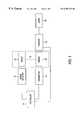
- FIG. 1is a block diagram of the present invention.
- FIG. 2is a block diagram illustrating a typical placement of antennas and the interrogation zone of the present invention.
- FIG. 3is a block diagram showing a second embodiment of that shown in FIG. 2 .
- FIG. 4is a block diagram illustrating an alternate embodiment for the antennas and the interrogation zone of the present invention.
- FIG. 5is a block diagram of an embodiment for detecting target direction.
- FIG. 6is a block diagram of an embodiment of that shown in FIG. 5 .
- the present inventionis shown comprising EAS transmitter 10 and range detector 12 connected to controller 14 , which is preferably a microprocessor.
- EAS receiver 16is connected to alarm 18 .
- Marker 20 and target 22are shown in interrogation zone 15 .
- Target 22which may pass through interrogation zone 15 without being associated with an active marker 20 , is illustrated connected to marker 20 by a dotted line.
- transmitter 10generates an electromagnetic field that is an interrogation electromagnetic field that substantially defines interrogation zone 15 .
- Controller 14controls the output power level of the electromagnetic field generated by transmitter 10 .
- Marker 20is adapted to resonate at a particular frequency when exposed to the electromagnetic field generated by transmitter 10 .
- Receiver 16detects the resonance of marker 20 and sends a signal to alarm 18 , which can be any type of indicator as known in the art.
- Transmitter 10 , marker 20 , receiver 16 and alarm 18are well known in the art.
- suitable EAS componentsis illustrated in U.S. Pat. No. 4,510,489, the disclosure of which is incorporated herein by reference.
- range detector 12For range detection using ultrasonic technology, range detector 12 generates a ranging pulse that impinges upon target 22 within interrogation zone 15 .
- Target 22is normally a person, but can be any other moving object such as a shopping cart. Target 22 may be carrying an article of merchandise to which marker 20 is attached.
- the ranging pulseis reflected off of target 22 back to detector 12 , which measures the time for the transmitted ranging pulse to travel round trip, as further described hereinbelow.
- Controller 14uses the round trip travel time of the ranging pulse to calculate the distance to target 22 and uses that distance to determine the desired output power level for transmitter 10 .
- a suitable ultrasonic range detectoris available from the Polaroid Company and is identified by product code number 604142.
- An alternate source for an ultrasonic range detectoris available from Murta Erie and is identified under the name MA40 series.
- EAS antennas, 30 and 32which transmit electromagnetic fields 34 and 36 , respectively.
- Two antennas 30 and 32are illustrated as many EAS systems utilize two antennas, however, systems having a single antenna or three or more antennas are contemplated herein.
- Antennas 30 and 32are each connected to one or more receivers 16 , for detecting an active marker 20 .
- One or more transmitters 10shown in FIG. 1, generate electromagnetic fields 34 and 36 that are transmitted by antennas 30 and 32 , respectively.
- Electromagnetic fields 34 and 36substantially define interrogation zone 38 .
- Interrogation zone 15is equivalent to interrogation zone 38 for the embodiment illustrated in FIG. 2 .
- Electromagnetic fields 34 and 36also define interrogation zones 40 and 42 , respectively.
- interrogation zones 40 and 42may be unintended interrogation zones of antennas 30 and 32 .
- Ranging transducer 44is mounted on or near antenna 30
- ranging transducer 46is mounted on or near antenna 32 . Ranging transducers 44 and 46 are adjusted to cover the interrogation zone 38 .
- a ranging detector 12shown in FIG. 1, generates ranging pulses that are transmitted by ranging transducers 44 and 46 . Alternately, a separate ranging detector 12 can be connected to each transducer 44 and 46 . If a target 22 is present in interrogation zone 38 , the ranging pulses will impinge upon target 22 and be reflected back to transducer 44 and 46 .
- the pulsesare timed so that if a target 22 is not present in interrogation zone 38 , transducer 46 (or 44 ) will not falsely detect pulses transmitted by transducer 44 (or 46 ).
- Timeis counted within detector 12 for each ranging pulse from the time a pulse is transmitted by either ranging transducer 44 or 46 , until it is reflected by a target 22 , and returns to the transmitting transducer to be detected by detector 12 .
- Controller 14uses the counted round trip travel time of the ranging pulses to calculate the distance between target 22 and ranging transducers 44 and 46 .
- Antennas 30 and 32are typically placed at the outer edges of a store exit, such that people must pass through interrogation zone 38 in order to exit the store.
- interrogation zones 40 and 42will be unintended interrogation zones and can result in unintended alarms by markers 20 inadvertently being placed within either of those zones.
- detection, within interrogation zone 38 , of target 22 , by ranging transducers 44 and 46 and range detector 12can be required before alarm 18 is activated by receiver 16 .
- controller 14When a target 22 (shown in FIG. 1) is detected within interrogation zone 38 by ranging detector 12 and ranging transducers 44 and 46 , the distance from target 22 to ranging transducers 44 and 46 is calculated by controller 14 .
- the distance calculated by controller 14 from the target 22 to ranging transducers 44 and 46will be equivalent to the distance from target 22 to antenna 30 and 32 , respectively, because ranging transducers 44 and 46 are mounted on or near antennas 30 and 32 , respectively.
- Controller 14according to the distances calculated to target 22 , will appropriately adjust the output power level of transmitter 10 .
- the power level associated with electromagnetic field 34will be reduced, and electromagnetic field 36 will be tuned off. If target 22 is detected within area 50 , the power level associated with electromagnetic field 36 will be reduced, and electromagnetic field 34 will be turned off.
- the determination of the proper power level associated with electromagnetic field 34 and 36will depend upon primarily two parameters, the first of which being the distance to target 22 from antenna 30 and 32 , respectively. Secondly, the output power level must be sufficient such that a marker 20 , which can be associated with an article carried by target 22 within interrogation zone 38 , will be in an electromagnetic field strong enough for detection of marker 20 by receiver 16 . Controller 14 can also simply turn on full output power when a target is anywhere within interrogation zone 38 , and turn the output power off when there is no target within interrogation zone 38 .
- one of the antennas, 30 and 32shown in FIG. 2, is configured to transmit only and the other antenna is configured to receive only.
- Antenna 31transmits only and antenna 33 receives only.
- the output power level associated with electromagnetic field 35will be controlled according to the distance calculated to target 22 from transducer 44 , and the minimum output power level required to insure detection of marker 20 by receiver 16 at the detected distance within interrogation zone 38 .
- Transducer 46can also be utilized to determine the distance to target 22 . While both are illustrated in FIG. 3, the distance to target 22 can be determined using only one transducer, 44 or 46 .
- FIG. 4an embodiment of the invention is illustrated for an EAS system having floor or ceiling mounted antennas 60 , 62 , and 64 .
- Ranging transducers 66 and 68are identical to transducers 44 and 46 discussed hereinabove.
- Floor or ceiling mounted antennasare typically used to cover very wide store exits. With floor or ceiling mounted antennas 60 , 62 , and 64 , areas 70 and 72 represent areas of uncertainty as to which antenna 60 or 62 , or 62 or 64 , respectively, may have detected a marker 20 . With wide exits it is often desirable to know where the marker 20 was detected in the interrogation zone so that an appropriate alarm can be activated.
- one or more controllers 14will determine the distance to a target 22 within interrogation zone 74 from both transducers 66 and 68 to determine which of areas 76 , 78 , or 80 the target is detected. The distance from transducers 66 and 68 to target 22 will thus be known. When a marker 20 associated with target 22 is detected, the areas of uncertainty, 70 and 72 , for the location of the detection of marker 20 , are eliminated because the position of target 22 will be known from the distances to transducers 66 and 68 . As described hereinabove for the embodiment illustrated in FIG. 2, the distance measurement to target 22 can be used to control the output power level associated with each antenna 60 , 62 , and 64 .
- the distance calculated from transducer 44 and 46may be to different targets.
- controller 14is programmed with the known distance between transducers 44 and 46 (or 66 and 68 ), and with an assumed size for the expected target, which is normally a person. If the distance calculated for the target 22 from transducer 44 (or 66 ) and from transducer 46 (or 68 ), plus the size of the expected target, does not equal the distance between transducers 44 and 46 (or 66 and 68 ), controller 14 determines that there must be multiple targets 22 in the interrogation zone.
- the output power levels of the electromagnetic fieldsare adjusted accordingly. For example, in the embodiment illustrated in FIG. 2 where both antennas 30 and 32 transmit and receive, if a target 22 is detected in area 49 by the distance calculated from transducer 44 , but simultaneously the distance calculated from transducer 46 indicates target 22 is in area 50 , then multiple targets are indicated.
- the output power levels for antenna 30 and antenna 32can thus be kept at maximum to be certain that a marker 20 anywhere within interrogation zone 38 is detected.
- An alternate selection for ranging detector 12is a microwave radar sensor, such as Siemens model KMY 24, sold by Infineon Technologies. As fully described hereinbelow, using a microwave radar sensor, the range to target 22 is determined differently than using the travel time of an ultrasonic pulse as described above.
- the preferred embodiment of the present invention, and selection of an ultrasonic detector or microwave radar sensordepends on the EAS system. Ultrasonic detection is preferred in microwave EAS systems operating at 2.45 GHz, which is the frequency of operation of the model KMY 24, and which may cause interference.
- Microwave radar sensorsare preferred in magnetomechanical EAS systems because the ultrasonic detector operates at about 50 KHz, which is near the frequency of operation of magnetomechanical EAS systems. However, ultrasonic detectors can operate during magnetomechanical EAS non-transmit periods and are useable.
- range detector 12transmits a microwave signal, which is reflected by target 22 .
- the amplitude change in the reflected signal, as compared to the transmitted signal,is detected by detector 12 and is supplied to controller 14 , which uses the amplitude change to determine range to target 22 .
- controller 14uses the amplitude change to determine range to target 22 .
- Range detector 12using a microwave radar sensor such as model KMY 24, can be used to determine the direction of motion of a target 22 as well as range. If a target 22 is moving within interrogation zone 15 , a Doppler effect or phase shift occurs in the transmitted microwave signal that is reflected off of target 22 . The reflected microwave signal from target 22 is compared to the transmitted microwave signal and the detected phase shift is positive or negative depending on whether target 22 is receding or approaching. Controller 14 uses the phase shift information to determine whether target 22 is entering or leaving a store having an interrogation zone 15 at the entrance/exit. Detection of an active marker 20 along with a target 22 exiting the store causes the activation of alarm 18 , which alerts appropriate store personnel that an article with an active marker 20 is being removed from the store.
- a microwave radar sensorsuch as model KMY 24
- EAS systemsare generally concerned with customers leaving a store with articles of merchandise.
- prior art EAS systemsif a customer tried to enter the store carrying an article having an active marker attached, when the active marker was detected in the interrogation zone an unintended alarm would be set off.
- the detection of marker 20is an unintended detection.
- appropriate store personnelcan be notified that the active marker 20 detected in interrogation zone 15 is an active marker 20 being carried into the store, and appropriate action can be taken.
- direction of motion of a moving target 22can be determined by controller 14 in the ultrasonic embodiment, described hereinabove, by using a plurality of ultrasonic transducers mounted on or near an antenna, or adjacent the intended interrogation zone.
- ultrasonic transducers 52 , 54 , and 56are mounted on or near antenna 50 .
- Three ultrasonic transducersare illustrated, but two, four or more ultrasonic transducers can be implemented and are contemplated herein.
- Ultrasonic transducers 52 , 54 , and 56are directed to ensonify regions 58 , 59 , and 60 , respectively.
- region 58is pointing within the store and region 60 is pointing out of the store
- detection of target 22 in region 60 prior to detection in region 59indicates a target entering the store. If an active marker 20 is detected within interrogation zone 51 along with detection of target 22 entering the store, detection of the marker 20 is unintended and appropriate store personnel can be notified that an active marker is being carried into the store.
- Detection of a target 22 in region 60 but not in region 59along with detection of an active marker 20 within interrogation zone 51 , indicates that someone is carrying an active marker 20 past the entrance of the store, but not entering, and no action need be taken.
- detection of a target 22 in region 58 but not in region 59along with detection of an active marker 20 within interrogation zone 51 , indicates that someone is carrying an active marker 20 past the exit of the store, but not exiting, and no action need be taken.
- direction information of target 22is obtainable by controller 14 from a single microwave sensor mounted at each antenna, 70 and 72 , or adjacent the intended interrogation zone.
- controller 14uses the microwave radar sensor embodiment described hereinabove direction information of target 22 to be obtainable by controller 14 from a single microwave sensor mounted at each antenna, 70 and 72 , or adjacent the intended interrogation zone.
- separate regions 58 , 59 , and 60would not need to be defined, as a single sensor ( 70 or 72 ) can detect directional information directly from the Doppler shift of the signal reflected from target 22 .
- Directional informationcan further be used by controller 14 to monitor the total number of people that enter and exit a store. Prior systems could count the number of people that passed through an entrance or exit, but without direction information, there was no way to determine whether a counted person was entering or exiting, only that the person was passing through the entrance or exit.
Landscapes
- Physics & Mathematics (AREA)
- General Physics & Mathematics (AREA)
- Engineering & Computer Science (AREA)
- Automation & Control Theory (AREA)
- Computer Security & Cryptography (AREA)
- Electromagnetism (AREA)
- Health & Medical Sciences (AREA)
- General Health & Medical Sciences (AREA)
- Toxicology (AREA)
- Multimedia (AREA)
- Radar Systems Or Details Thereof (AREA)
- Burglar Alarm Systems (AREA)
Abstract
Description
Claims (13)
Priority Applications (6)
| Application Number | Priority Date | Filing Date | Title |
|---|---|---|---|
| US09/382,066US6307473B1 (en) | 1999-08-24 | 1999-08-24 | Electronic article surveillance transmitter control using target range |
| CA002381248ACA2381248C (en) | 1999-08-24 | 2000-08-22 | Electronic article surveillance transmitter control using target range |
| AU67965/00AAU6796500A (en) | 1999-08-24 | 2000-08-22 | Electronic article surveillance transmitter control using target range |
| DE2000606143DE60006143T8 (en) | 1999-08-24 | 2000-08-22 | CONTROL OF THE TRANSMITTER OF AN ELECTRONIC GOODS SURVEILLANCE (EAS) BY TARGET DISTANCE |
| EP00955825AEP1216464B1 (en) | 1999-08-24 | 2000-08-22 | Electronic article surveillance transmitter control using target range |
| PCT/US2000/023027WO2001015103A1 (en) | 1999-08-24 | 2000-08-22 | Electronic article surveillance transmitter control using target range |
Applications Claiming Priority (1)
| Application Number | Priority Date | Filing Date | Title |
|---|---|---|---|
| US09/382,066US6307473B1 (en) | 1999-08-24 | 1999-08-24 | Electronic article surveillance transmitter control using target range |
Publications (1)
| Publication Number | Publication Date |
|---|---|
| US6307473B1true US6307473B1 (en) | 2001-10-23 |
Family
ID=23507402
Family Applications (1)
| Application Number | Title | Priority Date | Filing Date |
|---|---|---|---|
| US09/382,066Expired - LifetimeUS6307473B1 (en) | 1999-08-24 | 1999-08-24 | Electronic article surveillance transmitter control using target range |
Country Status (6)
| Country | Link |
|---|---|
| US (1) | US6307473B1 (en) |
| EP (1) | EP1216464B1 (en) |
| AU (1) | AU6796500A (en) |
| CA (1) | CA2381248C (en) |
| DE (1) | DE60006143T8 (en) |
| WO (1) | WO2001015103A1 (en) |
Cited By (61)
| Publication number | Priority date | Publication date | Assignee | Title |
|---|---|---|---|---|
| US6400273B1 (en)* | 2000-05-05 | 2002-06-04 | Sensormatic Electronics Corporation | EAS system with wide exit coverage and reduced over-range |
| US20020171545A1 (en)* | 2001-05-15 | 2002-11-21 | Hisashi Endo | Article care seal |
| US20020193685A1 (en)* | 2001-06-08 | 2002-12-19 | Calypso Medical, Inc. | Guided Radiation Therapy System |
| US20030171669A1 (en)* | 2002-03-11 | 2003-09-11 | Kopp Keith A. | MRI protector |
| US20030179127A1 (en)* | 2000-07-28 | 2003-09-25 | Hans-Theo Wienand | People counter |
| US6653940B2 (en) | 2000-12-15 | 2003-11-25 | Eastern Ribbon & Roll Corp. | Paper roll anti-theft protection |
| US20040041707A1 (en)* | 2002-09-03 | 2004-03-04 | Ricoh Company, Ltd. | Document security system |
| US20040041696A1 (en)* | 2002-09-03 | 2004-03-04 | Ricoh Company, Ltd. | Container for storing objects |
| US20040074961A1 (en)* | 2002-09-03 | 2004-04-22 | Ricoh Company, Ltd. | Method and apparatus for tracking documents in a workflow |
| US20040078749A1 (en)* | 2002-09-03 | 2004-04-22 | Ricoh Company, Ltd. | Techniques for determining electronic document information for paper documents |
| US20040079796A1 (en)* | 2002-09-03 | 2004-04-29 | Ricoh Company, Ltd. | Techniques for performing actions based upon physical locations of paper documents |
| US20040125916A1 (en)* | 2002-12-30 | 2004-07-01 | Herron Matthew A. | Panel-type sensor/source array assembly |
| US20040135687A1 (en)* | 2002-11-12 | 2004-07-15 | Qinetiq Limited | Ferromagnetic object detector |
| US20040207156A1 (en)* | 2003-04-17 | 2004-10-21 | Alliance Gaming Corporation | Wireless monitoring of playing cards and/or wagers in gaming |
| US20050028723A1 (en)* | 2002-02-19 | 2005-02-10 | Ancel Thomas A. | Loading dock traffic automation and inventory control system |
| US20050099299A1 (en)* | 2003-11-06 | 2005-05-12 | Honeywell International, Inc | Tracking, presence verification and locating features as part of a security system |
| US20050105724A1 (en)* | 2002-09-03 | 2005-05-19 | Ricoh Company, Ltd. | Techniques that facilitate tracking of physical locations of paper documents |
| US6911908B1 (en) | 1999-10-08 | 2005-06-28 | Activerf Limited | Security |
| US20050156723A1 (en)* | 2004-01-20 | 2005-07-21 | Masaki Fujii | Transponder startup control method and interrogator for tire pressure monitoring system |
| US20060111123A1 (en)* | 2002-08-19 | 2006-05-25 | Emerson Nerat | Wide area and large capacity intelligent object tracking system and method |
| US20060197652A1 (en)* | 2005-03-04 | 2006-09-07 | International Business Machines Corporation | Method and system for proximity tracking-based adaptive power control of radio frequency identification (RFID) interrogators |
| US20060276680A1 (en)* | 2002-12-30 | 2006-12-07 | Calypso Medical Technologies, Inc. | Apparatuses and methods for percutaneously implanting objects in patients |
| US20070030150A1 (en)* | 2005-08-02 | 2007-02-08 | International Business Machines Corporation | RFID reader having antenna with directional attenuation panels for determining RFID tag location |
| US20070040545A1 (en)* | 2003-06-05 | 2007-02-22 | Kiyoaki Takiguchi | Distance detection system |
| US20080001714A1 (en)* | 2004-12-08 | 2008-01-03 | Fujitsu Limited | Tag information selecting method, electronic apparatus and computer-readable storage medium |
| US20080061976A1 (en)* | 2006-09-01 | 2008-03-13 | Sensormatic Electronics Corporation | Radio frequency ID Doppler motion detector |
| US20090167307A1 (en)* | 2002-03-11 | 2009-07-02 | Keith Kopp | Ferromagnetic detection enhancer |
| US20090209804A1 (en)* | 2004-07-23 | 2009-08-20 | Calypso Medical Technologies, Inc. | Apparatuses and methods for percutaneously implanting objects in patients |
| US20090219189A1 (en)* | 2008-01-29 | 2009-09-03 | Honeywell International Inc. | Ground collision instrument for aircraft and marine vehicles |
| US20090299174A1 (en)* | 2004-01-12 | 2009-12-03 | Calypso Medical Technologies, Inc. | Instruments with location markers and methods for tracking instruments through anatomical passageways |
| US7684849B2 (en) | 2003-12-31 | 2010-03-23 | Calypso Medical Technologies, Inc. | Marker localization sensing system synchronized with radiation source |
| US7753779B2 (en) | 2006-06-16 | 2010-07-13 | Bally Gaming, Inc. | Gaming chip communication system and method |
| US7899513B2 (en) | 2004-07-23 | 2011-03-01 | Calypso Medical Technologies, Inc. | Modular software system for guided radiation therapy |
| US20110063086A1 (en)* | 2009-09-11 | 2011-03-17 | Toshiba Tec Kabushiki Kaisha | Rf tag reader and writer |
| US7926491B2 (en) | 2002-12-31 | 2011-04-19 | Calypso Medical Technologies, Inc. | Method and apparatus for sensing field strength signals to estimate location of a wireless implantable marker |
| CN102194268A (en)* | 2010-03-17 | 2011-09-21 | Ls产电株式会社 | Gate system |
| US8095203B2 (en) | 2004-07-23 | 2012-01-10 | Varian Medical Systems, Inc. | Data processing for real-time tracking of a target in radiation therapy |
| US8239005B2 (en) | 2004-07-23 | 2012-08-07 | Varian Medical Systems, Inc. | Systems and methods for real-time tracking of targets in radiation therapy and other medical applications |
| US8244330B2 (en) | 2004-07-23 | 2012-08-14 | Varian Medical Systems, Inc. | Integrated radiation therapy systems and methods for treating a target in a patient |
| US8272945B2 (en) | 2007-11-02 | 2012-09-25 | Bally Gaming, Inc. | Game related systems, methods, and articles that combine virtual and physical elements |
| US8325019B2 (en) | 2010-09-13 | 2012-12-04 | Ricoh Company, Ltd. | Motion tracking techniques for RFID tags |
| US20120321146A1 (en)* | 2011-06-06 | 2012-12-20 | Malay Kundu | Notification system and methods for use in retail environments |
| US8437449B2 (en) | 2004-07-23 | 2013-05-07 | Varian Medical Systems, Inc. | Dynamic/adaptive treatment planning for radiation therapy |
| US20130333483A1 (en)* | 2011-03-03 | 2013-12-19 | University Of Bradford | Methods and apparatus for detection of fluid interface fluctuations |
| US8647191B2 (en) | 2006-09-26 | 2014-02-11 | Bally Gaming, Inc. | Resonant gaming chip identification system and method |
| DE102014006978A1 (en) | 2014-05-14 | 2015-11-19 | ISW GmbH | A monitoring device and method for monitoring shopping carts when passing through a cash register |
| WO2015191395A1 (en)* | 2014-06-12 | 2015-12-17 | Tyco Fire & Security Gmbh | Systems and methods for adaptively controlling alarm issuance |
| US9237860B2 (en) | 2008-06-05 | 2016-01-19 | Varian Medical Systems, Inc. | Motion compensation for medical imaging and associated systems and methods |
| US9248003B2 (en) | 2002-12-30 | 2016-02-02 | Varian Medical Systems, Inc. | Receiver used in marker localization sensing system and tunable to marker frequency |
| US20160049058A1 (en)* | 2014-08-12 | 2016-02-18 | Tyco Fire & Security Gmbh | Electronic article surveillance systems implementing methods for determining security tag locations |
| US9311796B2 (en)* | 2014-08-22 | 2016-04-12 | Tyco Fire & Security Gmbh | Systems and methods for adaptively controlling a transmitter field |
| US9586059B2 (en) | 2004-07-23 | 2017-03-07 | Varian Medical Systems, Inc. | User interface for guided radiation therapy |
| US9919165B2 (en) | 2014-05-07 | 2018-03-20 | Varian Medical Systems, Inc. | Systems and methods for fiducial to plan association |
| US9943704B1 (en) | 2009-01-21 | 2018-04-17 | Varian Medical Systems, Inc. | Method and system for fiducials contained in removable device for radiation therapy |
| US10043284B2 (en) | 2014-05-07 | 2018-08-07 | Varian Medical Systems, Inc. | Systems and methods for real-time tumor tracking |
| US10182868B2 (en) | 2005-11-17 | 2019-01-22 | Varian Medical Systems, Inc. | Apparatus and methods for using an electromagnetic transponder in orthopedic procedures |
| US10195464B2 (en) | 2004-06-24 | 2019-02-05 | Varian Medical Systems, Inc. | Systems and methods for treating a lung of a patient using guided radiation therapy or surgery |
| US10293135B2 (en) | 2010-10-01 | 2019-05-21 | Varian Medical Systems, Inc. | Delivery catheter for and method of delivering implant, for example, bronchoscopically implanting a marker in a lung |
| US10653496B2 (en) | 2005-09-19 | 2020-05-19 | Varian Medical Systems, Inc. | Apparatus and methods for implanting objects, such as a bronchoscopically implanting markers in the lung of patients |
| WO2021076653A1 (en)* | 2019-10-14 | 2021-04-22 | Sensormatic Electronics, LLC | Validating radio frequency identification (rfid) tag alarm events |
| US12237076B2 (en) | 2019-08-30 | 2025-02-25 | Stryker Corporation | System and method for managing surgical articles during a surgical procedure |
Families Citing this family (3)
| Publication number | Priority date | Publication date | Assignee | Title |
|---|---|---|---|---|
| US20080284593A1 (en)* | 2007-05-17 | 2008-11-20 | Sensormatic Electronics Corporation | Method and system for power management of electronic article surveillance systems |
| ES2323928B1 (en)* | 2007-11-14 | 2010-05-13 | Jaime Perez Boils | PERFECTED ANTIHURT SYSTEM. |
| EP3809383B1 (en)* | 2014-08-05 | 2023-12-27 | Sensormatic Electronics, LLC | Systems and methods for adaptively controlling a transmitter field |
Citations (8)
| Publication number | Priority date | Publication date | Assignee | Title |
|---|---|---|---|---|
| DE2744317A1 (en) | 1977-10-01 | 1979-04-05 | Hartmut Ing Grad Unruh | Detection of unauthorised removal of objects - uses phased zone transmitters and time interval interpretation of responder signals |
| US4510489A (en) | 1982-04-29 | 1985-04-09 | Allied Corporation | Surveillance system having magnetomechanical marker |
| US4595915A (en)* | 1984-02-06 | 1986-06-17 | Mrs. Lawrence Israel | Electronic surveillance system employing the doppler effect |
| US5030941A (en)* | 1989-12-27 | 1991-07-09 | Checkpoint Systems, Inc. | Electronic article surveillance system incorporating an auxiliary sensor |
| US5661457A (en) | 1995-06-19 | 1997-08-26 | Sensormatic Electronics Corporation | Directional antenna configuration for asset tracking system |
| US6034604A (en) | 1999-01-14 | 2000-03-07 | Kaltner; George | Deactivation prevention for electronic article surveillance systems |
| US6084512A (en)* | 1998-10-02 | 2000-07-04 | Lucent Technologies, Inc. | Method and apparatus for electronic labeling and localizing |
| US6204765B1 (en)* | 1997-12-23 | 2001-03-20 | Inkrmec Ip Corp. | Method of detecting relative direction of motion of a radio frequency (RF) tag |
- 1999
- 1999-08-24USUS09/382,066patent/US6307473B1/ennot_activeExpired - Lifetime
- 2000
- 2000-08-22EPEP00955825Apatent/EP1216464B1/ennot_activeExpired - Lifetime
- 2000-08-22CACA002381248Apatent/CA2381248C/ennot_activeExpired - Lifetime
- 2000-08-22DEDE2000606143patent/DE60006143T8/enactiveActive
- 2000-08-22WOPCT/US2000/023027patent/WO2001015103A1/enactiveIP Right Grant
- 2000-08-22AUAU67965/00Apatent/AU6796500A/ennot_activeAbandoned
Patent Citations (8)
| Publication number | Priority date | Publication date | Assignee | Title |
|---|---|---|---|---|
| DE2744317A1 (en) | 1977-10-01 | 1979-04-05 | Hartmut Ing Grad Unruh | Detection of unauthorised removal of objects - uses phased zone transmitters and time interval interpretation of responder signals |
| US4510489A (en) | 1982-04-29 | 1985-04-09 | Allied Corporation | Surveillance system having magnetomechanical marker |
| US4595915A (en)* | 1984-02-06 | 1986-06-17 | Mrs. Lawrence Israel | Electronic surveillance system employing the doppler effect |
| US5030941A (en)* | 1989-12-27 | 1991-07-09 | Checkpoint Systems, Inc. | Electronic article surveillance system incorporating an auxiliary sensor |
| US5661457A (en) | 1995-06-19 | 1997-08-26 | Sensormatic Electronics Corporation | Directional antenna configuration for asset tracking system |
| US6204765B1 (en)* | 1997-12-23 | 2001-03-20 | Inkrmec Ip Corp. | Method of detecting relative direction of motion of a radio frequency (RF) tag |
| US6084512A (en)* | 1998-10-02 | 2000-07-04 | Lucent Technologies, Inc. | Method and apparatus for electronic labeling and localizing |
| US6034604A (en) | 1999-01-14 | 2000-03-07 | Kaltner; George | Deactivation prevention for electronic article surveillance systems |
Cited By (108)
| Publication number | Priority date | Publication date | Assignee | Title |
|---|---|---|---|---|
| US6911908B1 (en) | 1999-10-08 | 2005-06-28 | Activerf Limited | Security |
| US6400273B1 (en)* | 2000-05-05 | 2002-06-04 | Sensormatic Electronics Corporation | EAS system with wide exit coverage and reduced over-range |
| US20030179127A1 (en)* | 2000-07-28 | 2003-09-25 | Hans-Theo Wienand | People counter |
| US20040145479A1 (en)* | 2000-12-15 | 2004-07-29 | Collura Blaise J | Paper roll anti-theft protection |
| US6653940B2 (en) | 2000-12-15 | 2003-11-25 | Eastern Ribbon & Roll Corp. | Paper roll anti-theft protection |
| US20020171545A1 (en)* | 2001-05-15 | 2002-11-21 | Hisashi Endo | Article care seal |
| US7657301B2 (en) | 2001-06-08 | 2010-02-02 | Calypso Medical Technologies, Inc. | Guided radiation therapy system |
| US7657303B2 (en) | 2001-06-08 | 2010-02-02 | Calypso Medical Technologies, Inc. | Guided radiation therapy system |
| US7657302B2 (en) | 2001-06-08 | 2010-02-02 | Calypso Medical Technologies, Inc. | Guided radiation therapy system |
| US9072895B2 (en) | 2001-06-08 | 2015-07-07 | Varian Medical Systems, Inc. | Guided radiation therapy system |
| US20050261570A1 (en)* | 2001-06-08 | 2005-11-24 | Mate Timothy P | Guided radiation therapy system |
| US20040158146A1 (en)* | 2001-06-08 | 2004-08-12 | Mate Timothy P. | Guided radiation therapy system |
| US20040133101A1 (en)* | 2001-06-08 | 2004-07-08 | Mate Timothy P. | Guided radiation therapy system |
| US20020193685A1 (en)* | 2001-06-08 | 2002-12-19 | Calypso Medical, Inc. | Guided Radiation Therapy System |
| US20050028723A1 (en)* | 2002-02-19 | 2005-02-10 | Ancel Thomas A. | Loading dock traffic automation and inventory control system |
| US20090167307A1 (en)* | 2002-03-11 | 2009-07-02 | Keith Kopp | Ferromagnetic detection enhancer |
| US8148989B2 (en) | 2002-03-11 | 2012-04-03 | Keith Kopp | Ferromagnetic detection enhancer compatible with magnetic resonance |
| US20030171669A1 (en)* | 2002-03-11 | 2003-09-11 | Kopp Keith A. | MRI protector |
| US7489128B2 (en) | 2002-03-11 | 2009-02-10 | Kopp Keith A | MRI protector |
| US9616248B2 (en) | 2002-06-05 | 2017-04-11 | Varian Medical Systems, Inc. | Integrated radiation therapy systems and methods for treating a target in a patient |
| US9682253B2 (en) | 2002-06-05 | 2017-06-20 | Varian Medical Systems, Inc. | Integrated radiation therapy systems and methods for treating a target in a patient |
| US20060111123A1 (en)* | 2002-08-19 | 2006-05-25 | Emerson Nerat | Wide area and large capacity intelligent object tracking system and method |
| US7932812B2 (en) | 2002-08-19 | 2011-04-26 | Purelink Technology Inc. | Wide area and large capacity intelligent object tracking system and method |
| US7652555B2 (en) | 2002-09-03 | 2010-01-26 | Ricoh Company, Ltd. | Container for storing objects |
| US20040074961A1 (en)* | 2002-09-03 | 2004-04-22 | Ricoh Company, Ltd. | Method and apparatus for tracking documents in a workflow |
| US7506250B2 (en) | 2002-09-03 | 2009-03-17 | Ricoh Company, Ltd. | Techniques for determining electronic document information for paper documents |
| US6860422B2 (en) | 2002-09-03 | 2005-03-01 | Ricoh Company, Ltd. | Method and apparatus for tracking documents in a workflow |
| US20050105724A1 (en)* | 2002-09-03 | 2005-05-19 | Ricoh Company, Ltd. | Techniques that facilitate tracking of physical locations of paper documents |
| US7129840B2 (en) | 2002-09-03 | 2006-10-31 | Ricoh Company, Ltd. | Document security system |
| US7884955B2 (en) | 2002-09-03 | 2011-02-08 | Ricoh Company, Ltd. | Techniques for performing actions based upon physical locations of paper documents |
| US20040041707A1 (en)* | 2002-09-03 | 2004-03-04 | Ricoh Company, Ltd. | Document security system |
| US20040041696A1 (en)* | 2002-09-03 | 2004-03-04 | Ricoh Company, Ltd. | Container for storing objects |
| US20040079796A1 (en)* | 2002-09-03 | 2004-04-29 | Ricoh Company, Ltd. | Techniques for performing actions based upon physical locations of paper documents |
| US8493601B2 (en) | 2002-09-03 | 2013-07-23 | Ricoh Company Ltd. | Techniques for performing actions based upon physical locations of paper documents |
| US20040078749A1 (en)* | 2002-09-03 | 2004-04-22 | Ricoh Company, Ltd. | Techniques for determining electronic document information for paper documents |
| US20110140857A1 (en)* | 2002-09-03 | 2011-06-16 | Ricoh Company, Ltd. | Techniques for Performing Actions Based Upon Physical Locations of Paper Documents |
| US7357300B2 (en) | 2002-09-03 | 2008-04-15 | Ricoh Company, Ltd. | Method and apparatus for tracking documents in a workflow |
| US7424974B2 (en) | 2002-09-03 | 2008-09-16 | Ricoh Company, Ltd. | Techniques that facilitate tracking of physical locations of paper documents |
| US7113092B2 (en)* | 2002-11-12 | 2006-09-26 | Qinetiq Limited | Ferromagnetic object detector |
| US20040135687A1 (en)* | 2002-11-12 | 2004-07-15 | Qinetiq Limited | Ferromagnetic object detector |
| US9248003B2 (en) | 2002-12-30 | 2016-02-02 | Varian Medical Systems, Inc. | Receiver used in marker localization sensing system and tunable to marker frequency |
| US20060276680A1 (en)* | 2002-12-30 | 2006-12-07 | Calypso Medical Technologies, Inc. | Apparatuses and methods for percutaneously implanting objects in patients |
| US7912529B2 (en) | 2002-12-30 | 2011-03-22 | Calypso Medical Technologies, Inc. | Panel-type sensor/source array assembly |
| US20040125916A1 (en)* | 2002-12-30 | 2004-07-01 | Herron Matthew A. | Panel-type sensor/source array assembly |
| US7926491B2 (en) | 2002-12-31 | 2011-04-19 | Calypso Medical Technologies, Inc. | Method and apparatus for sensing field strength signals to estimate location of a wireless implantable marker |
| US7575234B2 (en) | 2003-04-17 | 2009-08-18 | Bally Gaming, Inc. | Wireless monitoring of playing cards and/or wagers in gaming |
| US20040207156A1 (en)* | 2003-04-17 | 2004-10-21 | Alliance Gaming Corporation | Wireless monitoring of playing cards and/or wagers in gaming |
| US20070040545A1 (en)* | 2003-06-05 | 2007-02-22 | Kiyoaki Takiguchi | Distance detection system |
| US8314619B2 (en)* | 2003-06-05 | 2012-11-20 | Sony Corporation | Distance detection system |
| US7113099B2 (en)* | 2003-11-06 | 2006-09-26 | Honeywell Internationakl, Inc. | Tracking, presence verification and locating features as part of a security system |
| US20050099299A1 (en)* | 2003-11-06 | 2005-05-12 | Honeywell International, Inc | Tracking, presence verification and locating features as part of a security system |
| US7684849B2 (en) | 2003-12-31 | 2010-03-23 | Calypso Medical Technologies, Inc. | Marker localization sensing system synchronized with radiation source |
| US20090299174A1 (en)* | 2004-01-12 | 2009-12-03 | Calypso Medical Technologies, Inc. | Instruments with location markers and methods for tracking instruments through anatomical passageways |
| US9623208B2 (en) | 2004-01-12 | 2017-04-18 | Varian Medical Systems, Inc. | Instruments with location markers and methods for tracking instruments through anatomical passageways |
| US20050156723A1 (en)* | 2004-01-20 | 2005-07-21 | Masaki Fujii | Transponder startup control method and interrogator for tire pressure monitoring system |
| US7336163B2 (en)* | 2004-01-20 | 2008-02-26 | Omron Corporation | Transponder startup control method and interrogator for tire pressure monitoring system |
| US10195464B2 (en) | 2004-06-24 | 2019-02-05 | Varian Medical Systems, Inc. | Systems and methods for treating a lung of a patient using guided radiation therapy or surgery |
| US11439847B2 (en) | 2004-06-24 | 2022-09-13 | Varian Medical Systems, Inc. | Systems and methods for treating a lung of a patient using guided radiation therapy or surgery |
| US7899513B2 (en) | 2004-07-23 | 2011-03-01 | Calypso Medical Technologies, Inc. | Modular software system for guided radiation therapy |
| US8340742B2 (en) | 2004-07-23 | 2012-12-25 | Varian Medical Systems, Inc. | Integrated radiation therapy systems and methods for treating a target in a patient |
| US8095203B2 (en) | 2004-07-23 | 2012-01-10 | Varian Medical Systems, Inc. | Data processing for real-time tracking of a target in radiation therapy |
| US9586059B2 (en) | 2004-07-23 | 2017-03-07 | Varian Medical Systems, Inc. | User interface for guided radiation therapy |
| US8239005B2 (en) | 2004-07-23 | 2012-08-07 | Varian Medical Systems, Inc. | Systems and methods for real-time tracking of targets in radiation therapy and other medical applications |
| US8244330B2 (en) | 2004-07-23 | 2012-08-14 | Varian Medical Systems, Inc. | Integrated radiation therapy systems and methods for treating a target in a patient |
| US9238151B2 (en) | 2004-07-23 | 2016-01-19 | Varian Medical Systems, Inc. | Dynamic/adaptive treatment planning for radiation therapy |
| US20090209804A1 (en)* | 2004-07-23 | 2009-08-20 | Calypso Medical Technologies, Inc. | Apparatuses and methods for percutaneously implanting objects in patients |
| US8437449B2 (en) | 2004-07-23 | 2013-05-07 | Varian Medical Systems, Inc. | Dynamic/adaptive treatment planning for radiation therapy |
| US20080001714A1 (en)* | 2004-12-08 | 2008-01-03 | Fujitsu Limited | Tag information selecting method, electronic apparatus and computer-readable storage medium |
| US20060197652A1 (en)* | 2005-03-04 | 2006-09-07 | International Business Machines Corporation | Method and system for proximity tracking-based adaptive power control of radio frequency identification (RFID) interrogators |
| US7518520B2 (en) | 2005-08-02 | 2009-04-14 | International Business Machines Corporation | RFID reader having antenna with directional attenuation panels for determining RFID tag location |
| US20070030150A1 (en)* | 2005-08-02 | 2007-02-08 | International Business Machines Corporation | RFID reader having antenna with directional attenuation panels for determining RFID tag location |
| US7323996B2 (en) | 2005-08-02 | 2008-01-29 | International Business Machines Corporation | RFID reader having antenna with directional attenuation panels for determining RFID tag location |
| US10653496B2 (en) | 2005-09-19 | 2020-05-19 | Varian Medical Systems, Inc. | Apparatus and methods for implanting objects, such as a bronchoscopically implanting markers in the lung of patients |
| US10182868B2 (en) | 2005-11-17 | 2019-01-22 | Varian Medical Systems, Inc. | Apparatus and methods for using an electromagnetic transponder in orthopedic procedures |
| US7753779B2 (en) | 2006-06-16 | 2010-07-13 | Bally Gaming, Inc. | Gaming chip communication system and method |
| US20080061976A1 (en)* | 2006-09-01 | 2008-03-13 | Sensormatic Electronics Corporation | Radio frequency ID Doppler motion detector |
| US8647191B2 (en) | 2006-09-26 | 2014-02-11 | Bally Gaming, Inc. | Resonant gaming chip identification system and method |
| US9514610B2 (en) | 2006-09-26 | 2016-12-06 | Bally Gaming, Inc. | Resonant gaming chip identification system and method |
| US8734245B2 (en) | 2007-11-02 | 2014-05-27 | Bally Gaming, Inc. | Game related systems, methods, and articles that combine virtual and physical elements |
| US8920236B2 (en) | 2007-11-02 | 2014-12-30 | Bally Gaming, Inc. | Game related systems, methods, and articles that combine virtual and physical elements |
| US8272945B2 (en) | 2007-11-02 | 2012-09-25 | Bally Gaming, Inc. | Game related systems, methods, and articles that combine virtual and physical elements |
| US9613487B2 (en) | 2007-11-02 | 2017-04-04 | Bally Gaming, Inc. | Game related systems, methods, and articles that combine virtual and physical elements |
| US8077081B2 (en)* | 2008-01-29 | 2011-12-13 | Honeywell International Inc. | Ground collision instrument for aircraft and marine vehicles |
| US20090219189A1 (en)* | 2008-01-29 | 2009-09-03 | Honeywell International Inc. | Ground collision instrument for aircraft and marine vehicles |
| US9237860B2 (en) | 2008-06-05 | 2016-01-19 | Varian Medical Systems, Inc. | Motion compensation for medical imaging and associated systems and methods |
| US9943704B1 (en) | 2009-01-21 | 2018-04-17 | Varian Medical Systems, Inc. | Method and system for fiducials contained in removable device for radiation therapy |
| US20110063086A1 (en)* | 2009-09-11 | 2011-03-17 | Toshiba Tec Kabushiki Kaisha | Rf tag reader and writer |
| US20110227701A1 (en)* | 2010-03-17 | 2011-09-22 | Ls Industrial Systems Co., Ltd. | Gate system |
| CN102194268A (en)* | 2010-03-17 | 2011-09-21 | Ls产电株式会社 | Gate system |
| US8742930B2 (en)* | 2010-03-17 | 2014-06-03 | Ls Industrial Systems Co., Ltd. | Gate system |
| US8325019B2 (en) | 2010-09-13 | 2012-12-04 | Ricoh Company, Ltd. | Motion tracking techniques for RFID tags |
| US10293135B2 (en) | 2010-10-01 | 2019-05-21 | Varian Medical Systems, Inc. | Delivery catheter for and method of delivering implant, for example, bronchoscopically implanting a marker in a lung |
| US20130333483A1 (en)* | 2011-03-03 | 2013-12-19 | University Of Bradford | Methods and apparatus for detection of fluid interface fluctuations |
| US20120321146A1 (en)* | 2011-06-06 | 2012-12-20 | Malay Kundu | Notification system and methods for use in retail environments |
| US10853856B2 (en)* | 2011-06-06 | 2020-12-01 | Ncr Corporation | Notification system and methods for use in retail environments |
| US9919165B2 (en) | 2014-05-07 | 2018-03-20 | Varian Medical Systems, Inc. | Systems and methods for fiducial to plan association |
| US10043284B2 (en) | 2014-05-07 | 2018-08-07 | Varian Medical Systems, Inc. | Systems and methods for real-time tumor tracking |
| DE102014006978A1 (en) | 2014-05-14 | 2015-11-19 | ISW GmbH | A monitoring device and method for monitoring shopping carts when passing through a cash register |
| AU2015275020B2 (en)* | 2014-06-12 | 2018-02-15 | Sensormatic Electronics Llc | Systems and methods for adaptively controlling alarm issuance |
| WO2015191395A1 (en)* | 2014-06-12 | 2015-12-17 | Tyco Fire & Security Gmbh | Systems and methods for adaptively controlling alarm issuance |
| KR20170032299A (en)* | 2014-06-12 | 2017-03-22 | 타이코 파이어 앤 시큐리티 게엠베하 | Systems and methods for adaptively controlling alarm issuance |
| US9275531B2 (en) | 2014-06-12 | 2016-03-01 | Tyco Fire & Security Gmbh | Systems and methods for adaptively controlling alarm issuance |
| US20160049058A1 (en)* | 2014-08-12 | 2016-02-18 | Tyco Fire & Security Gmbh | Electronic article surveillance systems implementing methods for determining security tag locations |
| US9342968B2 (en)* | 2014-08-12 | 2016-05-17 | Tyco Fire & Security Gmbh | Electronic article surveillance systems implementing methods for determining security tag locations |
| US9311796B2 (en)* | 2014-08-22 | 2016-04-12 | Tyco Fire & Security Gmbh | Systems and methods for adaptively controlling a transmitter field |
| US12237076B2 (en) | 2019-08-30 | 2025-02-25 | Stryker Corporation | System and method for managing surgical articles during a surgical procedure |
| WO2021076653A1 (en)* | 2019-10-14 | 2021-04-22 | Sensormatic Electronics, LLC | Validating radio frequency identification (rfid) tag alarm events |
| US11423751B2 (en) | 2019-10-14 | 2022-08-23 | Sensormatic Electronics, LLC | Validating radio frequency identification (RFID) tag alarm events |
Also Published As
| Publication number | Publication date |
|---|---|
| DE60006143D1 (en) | 2003-11-27 |
| EP1216464B1 (en) | 2003-10-22 |
| DE60006143T2 (en) | 2004-07-15 |
| AU6796500A (en) | 2001-03-19 |
| DE60006143T8 (en) | 2004-11-18 |
| WO2001015103A1 (en) | 2001-03-01 |
| EP1216464A1 (en) | 2002-06-26 |
| CA2381248C (en) | 2008-12-30 |
| CA2381248A1 (en) | 2001-03-01 |
Similar Documents
| Publication | Publication Date | Title |
|---|---|---|
| US6307473B1 (en) | Electronic article surveillance transmitter control using target range | |
| US8587432B2 (en) | Electronic article surveillance systems, apparatus, and methods | |
| CA2480628C (en) | System and method for optimizing range of an electronic article surveillance system | |
| US4595915A (en) | Electronic surveillance system employing the doppler effect | |
| KR100215984B1 (en) | Electronic Component Monitoring System Apparatus and Method Using Auxiliary Sensor | |
| AU2015324239B2 (en) | Systems and methods for intra-zone detection | |
| JP5371751B2 (en) | Method and system for controlling the interrogation area of a door-mounted antenna | |
| US6028518A (en) | System for verifying attachment of an EAS marker to an article after tagging | |
| JPH0798377A (en) | Collision-prevention alarm system and method for land vehicle | |
| US20080284593A1 (en) | Method and system for power management of electronic article surveillance systems | |
| EP1236188B1 (en) | Multi-technology in-line eas deactivation apparatus | |
| EP2153425A1 (en) | Method and system for reduction of electronic article surveillance system false alarms | |
| AU588159B2 (en) | Range limited coherent frequency doppler surveillance system | |
| EP1020829A2 (en) | Deactivation prevention for electronic article surveillance systems | |
| AU2001259460B2 (en) | EAS system with wide exit coverage and reduced over-range | |
| AU2001259460A1 (en) | EAS system with wide exit coverage and reduced over-range | |
| WO1997043741A1 (en) | Event detection device | |
| EP3347881B1 (en) | Systems and methods for variable detection based on traffic counter input | |
| HK1239935A1 (en) | Systems and methods for intra-zone detection | |
| HK1132573B (en) | Control for embedded and door-mounted antennas | |
| HK1139231A (en) | Method and system for power management of electronic article surveillance systems | |
| HK1169879A1 (en) | System and method for reducing cart alarms and increasing sensitivity in an eas system with metal shielding detection |
Legal Events
| Date | Code | Title | Description |
|---|---|---|---|
| AS | Assignment | Owner name:SENSORMATIC ELECTRONICS CORPORATION, FLORIDA Free format text:ASSIGNMENT OF ASSIGNORS INTEREST;ASSIGNORS:ZAMPINI, MICHAEL A.;TAYLOR, JOHN W.;REEL/FRAME:010198/0596 Effective date:19990824 | |
| STCF | Information on status: patent grant | Free format text:PATENTED CASE | |
| CC | Certificate of correction | ||
| AS | Assignment | Owner name:SENSORMATIC ELECTRONICS CORPORATION, FLORIDA Free format text:MERGER/CHANGE OF NAME;ASSIGNOR:SENSORMATIC ELECTRONICS CORPORATION;REEL/FRAME:012991/0641 Effective date:20011113 | |
| FPAY | Fee payment | Year of fee payment:4 | |
| FPAY | Fee payment | Year of fee payment:8 | |
| AS | Assignment | Owner name:SENSORMATIC ELECTRONICS, LLC,FLORIDA Free format text:MERGER;ASSIGNOR:SENSORMATIC ELECTRONICS CORPORATION;REEL/FRAME:024213/0049 Effective date:20090922 Owner name:SENSORMATIC ELECTRONICS, LLC, FLORIDA Free format text:MERGER;ASSIGNOR:SENSORMATIC ELECTRONICS CORPORATION;REEL/FRAME:024213/0049 Effective date:20090922 | |
| AS | Assignment | Owner name:ADT SERVICES GMBH, SWITZERLAND Free format text:ASSIGNMENT OF ASSIGNORS INTEREST;ASSIGNOR:SENSORMATIC ELECTRONICS, LLC;REEL/FRAME:029894/0856 Effective date:20130214 | |
| FPAY | Fee payment | Year of fee payment:12 | |
| AS | Assignment | Owner name:TYCO FIRE & SECURITY GMBH, SWITZERLAND Free format text:MERGER;ASSIGNOR:ADT SERVICES GMBH;REEL/FRAME:030290/0731 Effective date:20130326 | |
| AS | Assignment | Owner name:SENSORMATIC ELECTRONICS, LLC, FLORIDA Free format text:ASSIGNMENT OF ASSIGNORS INTEREST;ASSIGNOR:TYCO FIRE & SECURITY GMBH;REEL/FRAME:047182/0674 Effective date:20180927 | |
| AS | Assignment | Owner name:SENSORMATIC ELECTRONICS, LLC, FLORIDA Free format text:ASSIGNMENT OF ASSIGNORS INTEREST;ASSIGNOR:TYCO FIRE & SECURITY GMBH;REEL/FRAME:047188/0715 Effective date:20180927 |