US6307347B1 - Apparatus and method for recharging a vehicle - Google Patents
Apparatus and method for recharging a vehicleDownload PDFInfo
- Publication number
- US6307347B1 US6307347B1US09/630,925US63092500AUS6307347B1US 6307347 B1US6307347 B1US 6307347B1US 63092500 AUS63092500 AUS 63092500AUS 6307347 B1US6307347 B1US 6307347B1
- Authority
- US
- United States
- Prior art keywords
- relays
- relay
- vehicle
- signal
- contact
- Prior art date
- Legal status (The legal status is an assumption and is not a legal conclusion. Google has not performed a legal analysis and makes no representation as to the accuracy of the status listed.)
- Expired - Lifetime
Links
- 238000000034methodMethods0.000titleclaimsdescription6
- 238000004891communicationMethods0.000claimsdescription30
- 239000000463materialSubstances0.000claimsdescription3
- 230000004044responseEffects0.000claimsdescription2
- 230000008878couplingEffects0.000claims1
- 238000010168coupling processMethods0.000claims1
- 238000005859coupling reactionMethods0.000claims1
- 230000035772mutationEffects0.000claims1
- 239000012811non-conductive materialSubstances0.000claims1
- 241000237858GastropodaSpecies0.000description16
- XEEYBQQBJWHFJM-UHFFFAOYSA-NIronChemical compound[Fe]XEEYBQQBJWHFJM-UHFFFAOYSA-N0.000description2
- 230000005611electricityEffects0.000description2
- 241000878949Deroceras agresteSpecies0.000description1
- 230000006978adaptationEffects0.000description1
- 239000000853adhesiveSubstances0.000description1
- 230000001070adhesive effectEffects0.000description1
- 230000008859changeEffects0.000description1
- 238000002485combustion reactionMethods0.000description1
- 150000001875compoundsChemical class0.000description1
- 238000011161developmentMethods0.000description1
- 230000018109developmental processEffects0.000description1
- 230000007613environmental effectEffects0.000description1
- 238000010348incorporationMethods0.000description1
- 238000003780insertionMethods0.000description1
- 230000037431insertionEffects0.000description1
- 229910052742ironInorganic materials0.000description1
- 238000012986modificationMethods0.000description1
- 230000004048modificationEffects0.000description1
- 230000008569processEffects0.000description1
- 229910001220stainless steelInorganic materials0.000description1
- 239000010935stainless steelSubstances0.000description1
- 239000000126substanceSubstances0.000description1
Images


Classifications
- H—ELECTRICITY
- H02—GENERATION; CONVERSION OR DISTRIBUTION OF ELECTRIC POWER
- H02J—CIRCUIT ARRANGEMENTS OR SYSTEMS FOR SUPPLYING OR DISTRIBUTING ELECTRIC POWER; SYSTEMS FOR STORING ELECTRIC ENERGY
- H02J7/00—Circuit arrangements for charging or depolarising batteries or for supplying loads from batteries
- H02J7/0042—Circuit arrangements for charging or depolarising batteries or for supplying loads from batteries characterised by the mechanical construction
- B—PERFORMING OPERATIONS; TRANSPORTING
- B60—VEHICLES IN GENERAL
- B60L—PROPULSION OF ELECTRICALLY-PROPELLED VEHICLES; SUPPLYING ELECTRIC POWER FOR AUXILIARY EQUIPMENT OF ELECTRICALLY-PROPELLED VEHICLES; ELECTRODYNAMIC BRAKE SYSTEMS FOR VEHICLES IN GENERAL; MAGNETIC SUSPENSION OR LEVITATION FOR VEHICLES; MONITORING OPERATING VARIABLES OF ELECTRICALLY-PROPELLED VEHICLES; ELECTRIC SAFETY DEVICES FOR ELECTRICALLY-PROPELLED VEHICLES
- B60L53/00—Methods of charging batteries, specially adapted for electric vehicles; Charging stations or on-board charging equipment therefor; Exchange of energy storage elements in electric vehicles
- B60L53/10—Methods of charging batteries, specially adapted for electric vehicles; Charging stations or on-board charging equipment therefor; Exchange of energy storage elements in electric vehicles characterised by the energy transfer between the charging station and the vehicle
- B60L53/14—Conductive energy transfer
- B60L53/16—Connectors, e.g. plugs or sockets, specially adapted for charging electric vehicles
- B—PERFORMING OPERATIONS; TRANSPORTING
- B60—VEHICLES IN GENERAL
- B60L—PROPULSION OF ELECTRICALLY-PROPELLED VEHICLES; SUPPLYING ELECTRIC POWER FOR AUXILIARY EQUIPMENT OF ELECTRICALLY-PROPELLED VEHICLES; ELECTRODYNAMIC BRAKE SYSTEMS FOR VEHICLES IN GENERAL; MAGNETIC SUSPENSION OR LEVITATION FOR VEHICLES; MONITORING OPERATING VARIABLES OF ELECTRICALLY-PROPELLED VEHICLES; ELECTRIC SAFETY DEVICES FOR ELECTRICALLY-PROPELLED VEHICLES
- B60L53/00—Methods of charging batteries, specially adapted for electric vehicles; Charging stations or on-board charging equipment therefor; Exchange of energy storage elements in electric vehicles
- B60L53/30—Constructional details of charging stations
- B60L53/35—Means for automatic or assisted adjustment of the relative position of charging devices and vehicles
- B60L53/36—Means for automatic or assisted adjustment of the relative position of charging devices and vehicles by positioning the vehicle
- B—PERFORMING OPERATIONS; TRANSPORTING
- B60—VEHICLES IN GENERAL
- B60L—PROPULSION OF ELECTRICALLY-PROPELLED VEHICLES; SUPPLYING ELECTRIC POWER FOR AUXILIARY EQUIPMENT OF ELECTRICALLY-PROPELLED VEHICLES; ELECTRODYNAMIC BRAKE SYSTEMS FOR VEHICLES IN GENERAL; MAGNETIC SUSPENSION OR LEVITATION FOR VEHICLES; MONITORING OPERATING VARIABLES OF ELECTRICALLY-PROPELLED VEHICLES; ELECTRIC SAFETY DEVICES FOR ELECTRICALLY-PROPELLED VEHICLES
- B60L53/00—Methods of charging batteries, specially adapted for electric vehicles; Charging stations or on-board charging equipment therefor; Exchange of energy storage elements in electric vehicles
- B60L53/60—Monitoring or controlling charging stations
- B60L53/65—Monitoring or controlling charging stations involving identification of vehicles or their battery types
- Y—GENERAL TAGGING OF NEW TECHNOLOGICAL DEVELOPMENTS; GENERAL TAGGING OF CROSS-SECTIONAL TECHNOLOGIES SPANNING OVER SEVERAL SECTIONS OF THE IPC; TECHNICAL SUBJECTS COVERED BY FORMER USPC CROSS-REFERENCE ART COLLECTIONS [XRACs] AND DIGESTS
- Y02—TECHNOLOGIES OR APPLICATIONS FOR MITIGATION OR ADAPTATION AGAINST CLIMATE CHANGE
- Y02T—CLIMATE CHANGE MITIGATION TECHNOLOGIES RELATED TO TRANSPORTATION
- Y02T10/00—Road transport of goods or passengers
- Y02T10/60—Other road transportation technologies with climate change mitigation effect
- Y02T10/70—Energy storage systems for electromobility, e.g. batteries
- Y—GENERAL TAGGING OF NEW TECHNOLOGICAL DEVELOPMENTS; GENERAL TAGGING OF CROSS-SECTIONAL TECHNOLOGIES SPANNING OVER SEVERAL SECTIONS OF THE IPC; TECHNICAL SUBJECTS COVERED BY FORMER USPC CROSS-REFERENCE ART COLLECTIONS [XRACs] AND DIGESTS
- Y02—TECHNOLOGIES OR APPLICATIONS FOR MITIGATION OR ADAPTATION AGAINST CLIMATE CHANGE
- Y02T—CLIMATE CHANGE MITIGATION TECHNOLOGIES RELATED TO TRANSPORTATION
- Y02T10/00—Road transport of goods or passengers
- Y02T10/60—Other road transportation technologies with climate change mitigation effect
- Y02T10/7072—Electromobility specific charging systems or methods for batteries, ultracapacitors, supercapacitors or double-layer capacitors
- Y—GENERAL TAGGING OF NEW TECHNOLOGICAL DEVELOPMENTS; GENERAL TAGGING OF CROSS-SECTIONAL TECHNOLOGIES SPANNING OVER SEVERAL SECTIONS OF THE IPC; TECHNICAL SUBJECTS COVERED BY FORMER USPC CROSS-REFERENCE ART COLLECTIONS [XRACs] AND DIGESTS
- Y02—TECHNOLOGIES OR APPLICATIONS FOR MITIGATION OR ADAPTATION AGAINST CLIMATE CHANGE
- Y02T—CLIMATE CHANGE MITIGATION TECHNOLOGIES RELATED TO TRANSPORTATION
- Y02T90/00—Enabling technologies or technologies with a potential or indirect contribution to GHG emissions mitigation
- Y02T90/10—Technologies relating to charging of electric vehicles
- Y02T90/12—Electric charging stations
- Y—GENERAL TAGGING OF NEW TECHNOLOGICAL DEVELOPMENTS; GENERAL TAGGING OF CROSS-SECTIONAL TECHNOLOGIES SPANNING OVER SEVERAL SECTIONS OF THE IPC; TECHNICAL SUBJECTS COVERED BY FORMER USPC CROSS-REFERENCE ART COLLECTIONS [XRACs] AND DIGESTS
- Y02—TECHNOLOGIES OR APPLICATIONS FOR MITIGATION OR ADAPTATION AGAINST CLIMATE CHANGE
- Y02T—CLIMATE CHANGE MITIGATION TECHNOLOGIES RELATED TO TRANSPORTATION
- Y02T90/00—Enabling technologies or technologies with a potential or indirect contribution to GHG emissions mitigation
- Y02T90/10—Technologies relating to charging of electric vehicles
- Y02T90/14—Plug-in electric vehicles
- Y—GENERAL TAGGING OF NEW TECHNOLOGICAL DEVELOPMENTS; GENERAL TAGGING OF CROSS-SECTIONAL TECHNOLOGIES SPANNING OVER SEVERAL SECTIONS OF THE IPC; TECHNICAL SUBJECTS COVERED BY FORMER USPC CROSS-REFERENCE ART COLLECTIONS [XRACs] AND DIGESTS
- Y02—TECHNOLOGIES OR APPLICATIONS FOR MITIGATION OR ADAPTATION AGAINST CLIMATE CHANGE
- Y02T—CLIMATE CHANGE MITIGATION TECHNOLOGIES RELATED TO TRANSPORTATION
- Y02T90/00—Enabling technologies or technologies with a potential or indirect contribution to GHG emissions mitigation
- Y02T90/10—Technologies relating to charging of electric vehicles
- Y02T90/16—Information or communication technologies improving the operation of electric vehicles
- Y02T90/167—Systems integrating technologies related to power network operation and communication or information technologies for supporting the interoperability of electric or hybrid vehicles, i.e. smartgrids as interface for battery charging of electric vehicles [EV] or hybrid vehicles [HEV]
- Y—GENERAL TAGGING OF NEW TECHNOLOGICAL DEVELOPMENTS; GENERAL TAGGING OF CROSS-SECTIONAL TECHNOLOGIES SPANNING OVER SEVERAL SECTIONS OF THE IPC; TECHNICAL SUBJECTS COVERED BY FORMER USPC CROSS-REFERENCE ART COLLECTIONS [XRACs] AND DIGESTS
- Y04—INFORMATION OR COMMUNICATION TECHNOLOGIES HAVING AN IMPACT ON OTHER TECHNOLOGY AREAS
- Y04S—SYSTEMS INTEGRATING TECHNOLOGIES RELATED TO POWER NETWORK OPERATION, COMMUNICATION OR INFORMATION TECHNOLOGIES FOR IMPROVING THE ELECTRICAL POWER GENERATION, TRANSMISSION, DISTRIBUTION, MANAGEMENT OR USAGE, i.e. SMART GRIDS
- Y04S30/00—Systems supporting specific end-user applications in the sector of transportation
- Y04S30/10—Systems supporting the interoperability of electric or hybrid vehicles
- Y04S30/14—Details associated with the interoperability, e.g. vehicle recognition, authentication, identification or billing
Definitions
- the present inventionrelates to hybrid and electric vehicles.
- an apparatus for providing a source of current for rechargingis disclosed.
- Electric vehicleshave been available for many years. However, and due to certain limitations, the use of electric vehicles has been mainly in special applications. Recently, due to environmental considerations, as well as technological developments and advancements in the area of batteries, electric vehicles are gaining wider acceptance. In addition, and in certain regions of poor air quality, legislation has been adopted requiring that a percentage of new vehicles in these areas be electrically powered.
- Electric vehicleshave a number of advantages, including high efficiency, zero emissions, as well as being much quieter.
- the biggest drawback of an electric vehicleis that ultimately it must be recharged and accordingly it has a limited range. For many drivers, the range of an electric vehicle is sufficient and the vehicle's batteries can be recharged at the driver's residence or at a service location over night before the vehicle is driven again.
- a Hybrid Vehicleis a vehicle that has at least two sources of energy.
- a hybrid electric vehicle(HEV) is a vehicle wherein one of the sources of energy is electric and the other source of energy may be derived from a heat engine that burns diesel, gasoline or any other source of chemical energy. Accordingly, a hybrid electric vehicle may have a much greater range before its batteries need recharging.
- these vehiclesare also equipped with a means for charging the batteries through their onboard internal combustion engines.
- One contemplated means for recharging an electric or hybrid vehicleis an electric vehicle charging station wherein single plug devices having a system for metering time or power for billing the customer are used. These systems are expensive to install as well as operate. Another problem with current methods of charging electrical vehicles at charging stations is that the connector cables connecting the charging device to the vehicle are often exposed and difficult to handle.
- a further problem with charging stationsis that plug-in locations are often outdoors, exposed to the elements. Weather conditions, such as rain or snow, can impede the proper and safe operation of such electrical systems, which operate at high power levels.
- the buildings or housings associated with conventional charging stationsare constructed in a manner such that they are not convenient to install and to relocate in the event a change of location becomes necessary.
- the cost to build these structures, which are generally permanent structures,is high and most contemporary charging stations are single function units providing only charging services.
- a charging systemprovides a quick and efficient means for an operator to connect their vehicle to an electrical supply source in order to recharge their electric or hybrid electric vehicle.
- the charging systemcan be utilized at home and the vehicle operator does not have to manually connect the vehicle to a source of electric power. The operator simply positions their vehicle over the charging system of the instant application. There is no requirement for special connections or adaptations.
- systemis configured for use with a common household 120 volt AC supply.
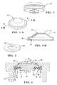
- FIG. 1is a top plan view of a charging mat constructed in accordance with the instant application
- FIG. 2is a diagrammatic view of portions of the apparatus of the instant application
- FIG. 3is a perspective view of component parts of the apparatus of the instant application.
- FIG. 4is a perspective view of component parts of the apparatus of the instant application.
- FIG. 5is a perspective view of component parts of the apparatus of the instant application.
- FIG. 6is a cross-section of view along lines 6 — 6 of FIG. 1;
- FIG. 7is a perspective view of component parts of the apparatus of the instant application.
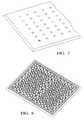
- FIG. 8is a perspective view of the lower portion of a charging mat of the instant application.
- FIG. 9is a perspective view of component parts of the apparatus of the instant application.
- FIG. 10is a side elevation of view illustrating operation of the instant application.
- FIG. 11is a cross-sectional view illustrating operation of the instant application.
- FIG. 12is a flowchart illustrating portions of a command sequence for the charging system of the present invention.
- charge mat 10constructed in accordance with the present invention is illustrated.
- Charge mat 10has a mat 12 that is constructed out of a durable rubber compound capable of withstanding the pressure on an accidental drive over by a vehicle operator.
- mat 12is also nonconductive to electricity and is able to conform to slight variations in the surface over which it is placed.
- mat 12is rectangular shaped and has the following dimensions, 100 cm ⁇ 80 cm. Of course, and as applications may require, these dimensions may vary. Charge mat 12 is also beveled along its periphery. This also prevents damage to mat 12 by accidental drive overs and, in addition, will reduce the likelihood of an individual tripping over mat 12 .
- Mat 12also includes a pair of relay fields 14 and 16 (illustrated by the dashed lines in FIG. 1 ).
- fields 14 and 16have the following dimensions, 40 cm ⁇ 50 cm. Of course, and as applications may require, these dimensions may vary.
- one of the relay fieldsperforms the function of electrical grounding while the other supplies household AC power.
- fields 14 and 16each have a plurality of highly magnetic permeable slugs 18 (FIG. 3 ).
- slugs 18are iron. Of course, other materials being magnetically permeable and having conductive qualities may be used for slugs 18 .
- mat 12has a plurality of openings 20 . Openings 20 are positioned to lie within fields 14 and 16 .
- a plurality of contact caps 22(FIG. 4) are inserted into openings 20 through the underside of mat 12 .
- contact caps 22are constructed out of magnetic stainless steel.
- slugs 18are configured to have a channel 24 disposed about the periphery of slugs 18 .
- Channel 24is configured to receive an elastomeric spring 26 (FIG. 5 ).
- Each opening 20is configured to tapered wall portion 28 and a receiving area 30 (FIG. 6 ).
- Each cap 22is configured to have an engagement surface 32 , an inclined portion 34 , a securement portion 36 and a receiving area 38 (FIG. 4 ).
- contact caps 22are inserted into openings 20 .
- the configuration of contact caps 22allows engagement surface 32 and a portion of inclined surface 34 to extend out through opening 20 .
- Securement portion 36is engaged and received within receiving area 30 , and the remaining portion of inclined surface 34 that does not extend through opening 20 makes contact with tapered wall portion 28 of opening 20 .
- contact caps 22are inserted into openings 20 and a retaining portion 39 is filled and behind contact cap 22 . Retaining portion 39 secures contact cap 22 in position.
- retaining portion 39is inserted and placed behind contact cap 22 .
- Retaining portion 39can be configured to have a snap fit with mat 12 .
- retaining portion 39may be secured to mat 12 with an adhesive.
- retaining portion 39may be configured to be part of mat 12 and flexible enough to allow for the insertion of contact cap 22 within opening 20 .
- contact caps 22may also be flexible enough to allow for the securement of contact caps 22 within opening 20 .
- Each Elastomeric spring 26has an inner opening 40 which is sufficiently large enough to allow the bottom portion of slugs 18 to pass through (FIG. 5 ). Elastomeric spring 26 is engaged within channel 24 of slugs 18 . As slugs 18 are inserted into contact caps 22 , the outer periphery of elastomeric spring 26 is engaged within receiving area 38 of contact caps 22 .
- slugs 18are suspended beneath contact caps 22 and an insulating airgap 42 is maintained between slugs 18 and contact caps 22 .
- Each slugis configured to have a wire 44 connected to a slug terminal 46 .
- Wire 44connects slug 18 to either an AC power supply or an electrical ground depending upon which relay field slug 18 is positioned in.
- FIGS. 7-9illustrate the top and bottom of charge mat 12 including openings 20 and a perspective view of slug 18 inserted into opening 20 .
- contact pads 48descend downwardly from the vehicle and make contact with at least one contact cap 20 of each field.
- contact pads 48are configured and dimensioned to have a surface area large enough to make contact with at least one or a maximum of four contact caps of each field. This allows contact pads 48 to make contact with at least one contact cap regardless of the positioning of the contact pad with respect to charge mat 12 .
- the dimensions of contact pads 48are 100 mm ⁇ 120 mm. Of course, and as applications may require, pads 48 can be configured to make contact with a lesser or larger amount of caps 22 as long as pads 48 still make contact with at least one contact cap.
- each contact pad 48has an electromagnet 50 positioned on the lower surface of contact pads 48 . Once the electromagnets make contact with contact caps 20 , the electromagnets activate and generate a magnetic force which will draw slug relays 18 towards contact cap 20 so that a portion of relay slug 18 makes contact with contact cap 20 . In this configuration charge mat 10 is now ready to supply an electrical charge to the contact pads of a vehicle.
- field 14is connected to an AC current supply through a power cord 52 .
- Power cord 52has an AC supply line 54 and a ground line 56 .
- AC supply line 54is connected to field 14 and ground line 56 is connected to field 16 .
- a relay 58connects supply line 54 to field 14 .
- an optional relay 60can be positioned along ground line 56 to connect ground line 56 to field 16 . The incorporation of an optional relay will prevent field 16 from being electrically charged through the inadvertent reverse polarity connection of power cord 52 into an electrical outlet.
- power cord 52is configured to be plugged into a typical North American AC outlet supplying 110 - 120 .
- power cord 52 and charge mat 10can be configured to accept higher or even lower voltage electrical sources.
- charge mat 10 and power cord 52can be configured to accommodate variations in electrical supply systems.
- a radio frequency communications module 62is connected to supply line 54 and ground line 56 .
- module 62is configured to supply relays 58 and 60 with commands which will connect their respective lines to their respective fields.
- the vehiclesends out a radio frequency signal to connect relays 58 and 60 after the charging pads have descended and made contact with at least one charging cap 22 to each field.
- the moduleinstructs relays 58 and 60 to close, and thus charging commences.
- the vehiclesends out a radio frequency signal to instruct module 62 to disconnect relays 58 and 60 . Accordingly, and through the use of module 62 and relays 58 and 60 , no electrical power is supplied to charge mat 10 until the contact pads of a vehicle are in place.
- the contact pads of the vehicledraw the relay slugs upwardly until a portion of the relay slug makes contact with the contact cap prior to the supply of an electrical current to the slugs.
- the process of drawing up the relay slugs and the contact of the contact pads to the contact cap prior to the connection of an electrical supply to charge mat 10prevents any arcing at the point of contact. This will prevent damage to contact caps 22 and relay slugs 18 .
- a pair of flowcharts 70illustrates portions of a command sequence for the charge mat operation protocol.
- the flow chartsillustrate the command sequence and operation protocol for the vehicle and the charge mat.
- a computer algorithm resident upon a microprocessor within the vehiclewill perform portions of the command sequence illustrated in FIG. 12 .
- Communications module 62in response to commands from the vehicle interface system also performs portions of the command sequence illustrated in FIG. 12 .
- a computer algorithm and a microprocessormay also be located within communications module 62 in order to perform portions of the command sequence illustrated in FIG. 12 .
- Communications module 62 of charge mat 10sends out a signal A which searches for a vehicle interface system.
- Signal Ais preferably sent out in five second intervals. Of course, this time limit or parameter may vary.
- a decision node 74evaluates the vehicle's charge condition and determines whether a charge is necessary. If so, step 76 instructs contact pads 48 to be lowered until electromagnets 50 make contact with at least one contact cap 20 of each field. Once contact has been made, a step 78 engages the electromagnets of the vehicle interface system and the magnetic field at contact pad 48 will draw local relay slugs 18 upward until a portion of slugs 18 makes contact with contact cap 22 .
- a step 80instructs the vehicle interface system to send out an enable AC signal (signal B).
- Signal Bis received by communications module 62 of charge mat 10 , and communication module 62 instructs relay 58 and, if installed, relay 60 to close, effectively completing the circuit of charge mat 10 wherein electrical power is now supplied to the vehicle interface system.
- a step 81instructs the vehicle interface system to send out an enable AC signal (signal B).
- Signal Bis received by communications module 62 of charge mat 10 , and communication module 62 instructs relay 58 and, if installed, relay 60 to close, effectively completing the circuit of charge mat 10 wherein electrical power is now supplied to the vehicle interface system.
- a decision node 82determines whether the charging sequence is complete. This is accomplished by accessing the current state charge of the vehicle's battery system. If the charge is complete, a step 84 sends out a charge complete signal (signal C). Signal C is received by communications module 62 of charge mat 10 and relays 58 and 60 are opened. This is illustrated by a step 85 . Once relays 58 and 60 are opened, communication module 62 sends out a retract signal D and once signal D is received by the vehicle interface system, a step 86 instructs the pads to retract.
- the vehicle interface systemis equipped with a charge tapering system wherein the charging current is tapered off as the completion of a charge is approached to ensure battery cell voltage uniformity.
- the charge mat of the instant applicationallows a vehicle operator to recharge an electric or hybrid electric vehicle by performing no unnecessary tasks other than parking their vehicle in a garage or other place of overnight storage.
- the usersimply locates the charge mat in an area where the vehicle is parked for extended periods such as overnight parking.
- the charge matis normally kept plugged into a conventional 110-120 volt AC outlet and the user simply aligns the vehicle and its retractable charging pads (located in the front, midsection or rear portion of the vehicle) and places the automobile in park.
Landscapes
- Engineering & Computer Science (AREA)
- Power Engineering (AREA)
- Transportation (AREA)
- Mechanical Engineering (AREA)
- Electric Propulsion And Braking For Vehicles (AREA)
- Charge And Discharge Circuits For Batteries Or The Like (AREA)
Abstract
Description
Claims (33)
Priority Applications (2)
| Application Number | Priority Date | Filing Date | Title |
|---|---|---|---|
| US09/630,925US6307347B1 (en) | 2000-08-02 | 2000-08-02 | Apparatus and method for recharging a vehicle |
| DE10137526ADE10137526A1 (en) | 2000-08-02 | 2001-08-01 | Device and method for recharging a vehicle |
Applications Claiming Priority (1)
| Application Number | Priority Date | Filing Date | Title |
|---|---|---|---|
| US09/630,925US6307347B1 (en) | 2000-08-02 | 2000-08-02 | Apparatus and method for recharging a vehicle |
Publications (1)
| Publication Number | Publication Date |
|---|---|
| US6307347B1true US6307347B1 (en) | 2001-10-23 |
Family
ID=24529132
Family Applications (1)
| Application Number | Title | Priority Date | Filing Date |
|---|---|---|---|
| US09/630,925Expired - LifetimeUS6307347B1 (en) | 2000-08-02 | 2000-08-02 | Apparatus and method for recharging a vehicle |
Country Status (2)
| Country | Link |
|---|---|
| US (1) | US6307347B1 (en) |
| DE (1) | DE10137526A1 (en) |
Cited By (15)
| Publication number | Priority date | Publication date | Assignee | Title |
|---|---|---|---|---|
| US6774602B2 (en) | 2002-06-14 | 2004-08-10 | Delphi Technologies, Inc. | Apparatus and method for providing temporary power |
| US20100201309A1 (en)* | 2009-02-10 | 2010-08-12 | Meek Ivan C | Systems and methods for coupling a vehicle to an external grid and/or network |
| US20100237985A1 (en)* | 2009-03-18 | 2010-09-23 | Greenit!, Inc. | Method, system, and apparatus for distributing electricity to electric vehicles, monitoring the distribution thereof, and/or controlling the distribution thereof |
| US8307967B2 (en) | 2007-07-04 | 2012-11-13 | Satyajit Patwardhan | Widely deployable charging system for vehicles |
| US8725330B2 (en) | 2010-06-02 | 2014-05-13 | Bryan Marc Failing | Increasing vehicle security |
| JP2014150642A (en)* | 2013-01-31 | 2014-08-21 | Toshiba Corp | Charging system |
| CN104627016A (en)* | 2014-12-22 | 2015-05-20 | 北京新能源汽车股份有限公司 | Extended range electric vehicle control method based on state management |
| US10286799B2 (en)* | 2016-08-23 | 2019-05-14 | GM Global Technology Operations LLC | Hands-free conductive battery charger for an electric vehicle |
| US20200269714A1 (en)* | 2017-09-12 | 2020-08-27 | easE-Link GmbH | Vehicle connection device, ground contact unit, vehicle coupling system and method for automatically conductively connecting a vehicle contact unit with a ground contact unit |
| US10840636B2 (en) | 2016-03-25 | 2020-11-17 | easE-Link GmbH | Contacting system for producing an electrical connection between a primary device and a secondary device |
| WO2021089309A1 (en)* | 2019-11-04 | 2021-05-14 | Contitech Antriebssysteme Gmbh | System for generating a charging voltage for charging a battery of a vehicle |
| US20220072970A1 (en)* | 2020-09-09 | 2022-03-10 | Audi Ag | Energy storage device for electric energy, charging arrangement and method for installing an energy storage device or charging arrangement |
| US20220144107A1 (en)* | 2020-11-12 | 2022-05-12 | Rivian Ip Holdings, Llc | Automated plug-in system and method |
| US11524594B2 (en) | 2016-03-25 | 2022-12-13 | Easelink Gmbh | Contact system for establishing an electric connection between a vehicle and a power supply |
| US20220402383A1 (en)* | 2021-06-21 | 2022-12-22 | Toyota Jidosha Kabushiki Kaisha | Method for providing vehicle charging service, and vehicle charging system |
Families Citing this family (3)
| Publication number | Priority date | Publication date | Assignee | Title |
|---|---|---|---|---|
| DE102008009166A1 (en)* | 2008-02-14 | 2009-08-20 | Jungheinrich Aktiengesellschaft | Contacting system for battery-powered industrial trucks |
| DE102009001080A1 (en) | 2009-02-23 | 2010-08-26 | Robert Bosch Gmbh | Autonomous charging device for Plugln hybrid vehicles |
| DE102010063665A1 (en)* | 2010-12-21 | 2012-06-21 | Siemens Aktiengesellschaft | Method for guiding electric car to charging position, involves determining position data of car from measured distance and measured angles based on charging position, where position data serve as basis for starting electric car |
Citations (4)
| Publication number | Priority date | Publication date | Assignee | Title |
|---|---|---|---|---|
| US5583418A (en) | 1991-05-31 | 1996-12-10 | Honda Giken Kogyo Kabushiki Kaisha | Battery charging station for electric vehicles and electric vehicle usable therewith |
| US5696367A (en)* | 1993-04-19 | 1997-12-09 | Keith; Arlie L. | Charging batteries of electric vehicles |
| US5821728A (en)* | 1996-07-22 | 1998-10-13 | Schwind; John P. | Armature induction charging of moving electric vehicle batteries |
| US5847537A (en) | 1996-10-19 | 1998-12-08 | Parmley, Sr.; Daniel W. | Electric vehicle charging station system |
- 2000
- 2000-08-02USUS09/630,925patent/US6307347B1/ennot_activeExpired - Lifetime
- 2001
- 2001-08-01DEDE10137526Apatent/DE10137526A1/ennot_activeWithdrawn
Patent Citations (4)
| Publication number | Priority date | Publication date | Assignee | Title |
|---|---|---|---|---|
| US5583418A (en) | 1991-05-31 | 1996-12-10 | Honda Giken Kogyo Kabushiki Kaisha | Battery charging station for electric vehicles and electric vehicle usable therewith |
| US5696367A (en)* | 1993-04-19 | 1997-12-09 | Keith; Arlie L. | Charging batteries of electric vehicles |
| US5821728A (en)* | 1996-07-22 | 1998-10-13 | Schwind; John P. | Armature induction charging of moving electric vehicle batteries |
| US5847537A (en) | 1996-10-19 | 1998-12-08 | Parmley, Sr.; Daniel W. | Electric vehicle charging station system |
Cited By (30)
| Publication number | Priority date | Publication date | Assignee | Title |
|---|---|---|---|---|
| US6774602B2 (en) | 2002-06-14 | 2004-08-10 | Delphi Technologies, Inc. | Apparatus and method for providing temporary power |
| US8307967B2 (en) | 2007-07-04 | 2012-11-13 | Satyajit Patwardhan | Widely deployable charging system for vehicles |
| US20100201309A1 (en)* | 2009-02-10 | 2010-08-12 | Meek Ivan C | Systems and methods for coupling a vehicle to an external grid and/or network |
| US20100237985A1 (en)* | 2009-03-18 | 2010-09-23 | Greenit!, Inc. | Method, system, and apparatus for distributing electricity to electric vehicles, monitoring the distribution thereof, and/or controlling the distribution thereof |
| US20100241560A1 (en)* | 2009-03-18 | 2010-09-23 | Greenit!, Inc. | Method, system, and apparatus for distributing electricity to electric vehicles, monitoring the distribution thereof, and/or providing automated billing |
| US8564403B2 (en) | 2009-03-18 | 2013-10-22 | Mario Landau-Holdsworth | Method, system, and apparatus for distributing electricity to electric vehicles, monitoring the distribution thereof, and/or controlling the distribution thereof |
| US9751417B2 (en) | 2009-03-18 | 2017-09-05 | Evercharge, Inc. | Method, system, and apparatus for distributing electricity to electric vehicles, monitoring the distribution thereof, and/or providing automated billing |
| US8725330B2 (en) | 2010-06-02 | 2014-05-13 | Bryan Marc Failing | Increasing vehicle security |
| US8841881B2 (en) | 2010-06-02 | 2014-09-23 | Bryan Marc Failing | Energy transfer with vehicles |
| US11186192B1 (en) | 2010-06-02 | 2021-11-30 | Bryan Marc Failing | Improving energy transfer with vehicles |
| US9114719B1 (en) | 2010-06-02 | 2015-08-25 | Bryan Marc Failing | Increasing vehicle security |
| US9393878B1 (en) | 2010-06-02 | 2016-07-19 | Bryan Marc Failing | Energy transfer with vehicles |
| US10124691B1 (en) | 2010-06-02 | 2018-11-13 | Bryan Marc Failing | Energy transfer with vehicles |
| JP2014150642A (en)* | 2013-01-31 | 2014-08-21 | Toshiba Corp | Charging system |
| CN104627016B (en)* | 2014-12-22 | 2017-10-20 | 北京新能源汽车股份有限公司 | Extended range electric vehicle control method based on state management |
| CN104627016A (en)* | 2014-12-22 | 2015-05-20 | 北京新能源汽车股份有限公司 | Extended range electric vehicle control method based on state management |
| US10840636B2 (en) | 2016-03-25 | 2020-11-17 | easE-Link GmbH | Contacting system for producing an electrical connection between a primary device and a secondary device |
| US11524594B2 (en) | 2016-03-25 | 2022-12-13 | Easelink Gmbh | Contact system for establishing an electric connection between a vehicle and a power supply |
| US10286799B2 (en)* | 2016-08-23 | 2019-05-14 | GM Global Technology Operations LLC | Hands-free conductive battery charger for an electric vehicle |
| US11634040B2 (en)* | 2017-09-12 | 2023-04-25 | Easelink Gmbh | Vehicle connection device, ground contact unit, vehicle coupling system and method for automatically conductively connecting a vehicle contact unit with a ground contact unit |
| US20200269714A1 (en)* | 2017-09-12 | 2020-08-27 | easE-Link GmbH | Vehicle connection device, ground contact unit, vehicle coupling system and method for automatically conductively connecting a vehicle contact unit with a ground contact unit |
| US12005791B2 (en)* | 2017-09-12 | 2024-06-11 | Easelink Gmbh | Vehicle connection device, ground contact unit, vehicle coupling system and method for automatically conductively connecting a vehicle contact unit with a ground contact unit |
| US20230356608A1 (en)* | 2017-09-12 | 2023-11-09 | Easelink Gmbh | Vehicle connection device, ground contact unit, vehicle coupling system and method for automatically conductively connecting a vehicle contact unit with a ground contact unit |
| WO2021089309A1 (en)* | 2019-11-04 | 2021-05-14 | Contitech Antriebssysteme Gmbh | System for generating a charging voltage for charging a battery of a vehicle |
| US20220072970A1 (en)* | 2020-09-09 | 2022-03-10 | Audi Ag | Energy storage device for electric energy, charging arrangement and method for installing an energy storage device or charging arrangement |
| US12311791B2 (en)* | 2020-09-09 | 2025-05-27 | Audi Ag | Energy storage device for electric energy, charging arrangement and method for installing an energy storage device or charging arrangement |
| US20220144107A1 (en)* | 2020-11-12 | 2022-05-12 | Rivian Ip Holdings, Llc | Automated plug-in system and method |
| US11904715B2 (en)* | 2020-11-12 | 2024-02-20 | Rivian Ip Holdings, Llc | Automated plug-in system and method |
| US20220402383A1 (en)* | 2021-06-21 | 2022-12-22 | Toyota Jidosha Kabushiki Kaisha | Method for providing vehicle charging service, and vehicle charging system |
| US12344106B2 (en)* | 2021-06-21 | 2025-07-01 | Toyota Jidosha Kabushiki Kaisha | Method for providing vehicle charging service, and vehicle charging system |
Also Published As
| Publication number | Publication date |
|---|---|
| DE10137526A1 (en) | 2002-06-06 |
Similar Documents
| Publication | Publication Date | Title |
|---|---|---|
| US6307347B1 (en) | Apparatus and method for recharging a vehicle | |
| US10442301B2 (en) | Multi-protocol charge port for an electric vehicle | |
| KR101764496B1 (en) | Active rectifier for wireless power transfer system and vehicle assembly using same and operating method thereof | |
| CN101292408B (en) | Recharging station and related electric vehicle | |
| WO2019010375A1 (en) | An apparatus that automates the connecting process between a primary connector and a secondary connector for charging an electric vehicle | |
| CN103915866A (en) | Method and apparatus for high-voltage DC charging of battery-electric and plug-in hybrid electric vehicles | |
| US20170291498A1 (en) | Electric vehicle charger connections made by vehicle motion only | |
| CN114559849B (en) | Mobile charging control method and system | |
| CN208343949U (en) | A kind of charging system applied based on electric vehicle in field | |
| CN108482177A (en) | It is a kind of can autopatching connector | |
| JP4204184B2 (en) | Inductive charging connector for electric vehicles | |
| CN105119355A (en) | Intelligent wireless charging device used for electric automobile | |
| CN112158085A (en) | Multifunctional charging gun for electric automobile | |
| KR102184000B1 (en) | Charge system and interface apparatus | |
| CN216783299U (en) | Car-to-car charging circuit, charging harness, charging system and electric vehicle | |
| CN106026280A (en) | Wireless intelligent charging system | |
| US20170291496A1 (en) | Automatic, dual power, inductive and conductive charger for electric cars. | |
| CN212604553U (en) | Charging device for electric automobile | |
| CN208069426U (en) | Road type mobile charging system | |
| CN210137207U (en) | Dual-purpose vehicle charging pile | |
| CN208813013U (en) | It is a kind of to draw the direct-current charging post connect convenient for cabling | |
| CN217804347U (en) | Charging equipment for connecting charging of new energy automobile | |
| US20230079648A1 (en) | Ev charging system & method | |
| CN109050343A (en) | It is a kind of to draw the direct-current charging post connect convenient for cabling | |
| CN211869170U (en) | Electric bow device for electric automobile, charging pile and electric automobile |
Legal Events
| Date | Code | Title | Description |
|---|---|---|---|
| AS | Assignment | Owner name:DELPHI TECHNOLOGIES, INC., MICHIGAN Free format text:ASSIGNMENT OF ASSIGNORS INTEREST;ASSIGNOR:RONNING, JEFFREY J.;REEL/FRAME:011017/0745 Effective date:20000717 | |
| STCF | Information on status: patent grant | Free format text:PATENTED CASE | |
| FPAY | Fee payment | Year of fee payment:4 | |
| REMI | Maintenance fee reminder mailed | ||
| FPAY | Fee payment | Year of fee payment:8 | |
| SULP | Surcharge for late payment | Year of fee payment:7 | |
| FPAY | Fee payment | Year of fee payment:12 | |
| AS | Assignment | Owner name:DYNAVAIR, LLC, TEXAS Free format text:ASSIGNMENT OF ASSIGNORS INTEREST;ASSIGNOR:POWER IP, LLC;REEL/FRAME:039020/0288 Effective date:20140407 | |
| AS | Assignment | Owner name:POWER IP, LLC, TEXAS Free format text:ASSIGNMENT OF ASSIGNORS INTEREST;ASSIGNOR:DELPHI TECHNOLOGIES, INC;REEL/FRAME:039034/0807 Effective date:20111111 | |
| AS | Assignment | Owner name:POWER IP, LLC, TEXAS Free format text:CORRECTIVE ASSIGNMENT TO CORRECT THE 3 APPLICATION NUMBER 10105508, 10146556, AND 10158062 PREVIOUSLY RECORDED ON REEL 039034 FRAME 0807. ASSIGNOR(S) HEREBY CONFIRMS THE ASSIGNMENT;ASSIGNOR:DELPHI TECHNOLOGIES, INC;REEL/FRAME:046425/0136 Effective date:20111111 |