US6306531B1 - Combustor air flow control method for fuel cell apparatus - Google Patents
Combustor air flow control method for fuel cell apparatusDownload PDFInfo
- Publication number
- US6306531B1 US6306531B1US09/565,781US56578100AUS6306531B1US 6306531 B1US6306531 B1US 6306531B1US 56578100 AUS56578100 AUS 56578100AUS 6306531 B1US6306531 B1US 6306531B1
- Authority
- US
- United States
- Prior art keywords
- combustor
- air flow
- fuel
- air
- fuel cell
- Prior art date
- Legal status (The legal status is an assumption and is not a legal conclusion. Google has not performed a legal analysis and makes no representation as to the accuracy of the status listed.)
- Expired - Lifetime
Links
- 239000000446fuelSubstances0.000titleclaimsabstractdescription285
- 238000000034methodMethods0.000titleclaimsabstractdescription41
- QVGXLLKOCUKJST-UHFFFAOYSA-Natomic oxygenChemical compound[O]QVGXLLKOCUKJST-UHFFFAOYSA-N0.000claimsabstractdescription26
- 239000001301oxygenSubstances0.000claimsabstractdescription26
- 229910052760oxygenInorganic materials0.000claimsabstractdescription26
- 230000001105regulatory effectEffects0.000claimsabstractdescription15
- 230000004044responseEffects0.000claimsabstractdescription15
- 239000000470constituentSubstances0.000claimsabstractdescription14
- 230000008859changeEffects0.000claimsabstractdescription11
- 230000001276controlling effectEffects0.000claimsabstractdescription11
- 239000001257hydrogenSubstances0.000claimsdescription39
- 229910052739hydrogenInorganic materials0.000claimsdescription39
- UFHFLCQGNIYNRP-UHFFFAOYSA-NHydrogenChemical compound[H][H]UFHFLCQGNIYNRP-UHFFFAOYSA-N0.000claimsdescription33
- 229930195733hydrocarbonNatural products0.000claimsdescription5
- 150000002430hydrocarbonsChemical class0.000claimsdescription5
- 239000004215Carbon black (E152)Substances0.000claimsdescription4
- 238000007599dischargingMethods0.000claimsdescription4
- 230000000740bleeding effectEffects0.000claims2
- 230000009977dual effectEffects0.000abstract1
- OKKJLVBELUTLKV-UHFFFAOYSA-NMethanolChemical compoundOCOKKJLVBELUTLKV-UHFFFAOYSA-N0.000description148
- 150000002431hydrogenChemical class0.000description54
- 229910001868waterInorganic materials0.000description35
- 239000000203mixtureSubstances0.000description25
- 239000006200vaporizerSubstances0.000description24
- 238000006243chemical reactionMethods0.000description22
- 239000003054catalystSubstances0.000description20
- 239000007788liquidSubstances0.000description20
- 239000007789gasSubstances0.000description16
- CURLTUGMZLYLDI-UHFFFAOYSA-NCarbon dioxideChemical compoundO=C=OCURLTUGMZLYLDI-UHFFFAOYSA-N0.000description15
- 230000007423decreaseEffects0.000description15
- 239000012895dilutionSubstances0.000description15
- 238000010790dilutionMethods0.000description15
- XLYOFNOQVPJJNP-UHFFFAOYSA-NwaterSubstancesOXLYOFNOQVPJJNP-UHFFFAOYSA-N0.000description15
- 229910002092carbon dioxideInorganic materials0.000description12
- IJGRMHOSHXDMSA-UHFFFAOYSA-NAtomic nitrogenChemical compoundN#NIJGRMHOSHXDMSA-UHFFFAOYSA-N0.000description11
- 230000001590oxidative effectEffects0.000description8
- 238000002485combustion reactionMethods0.000description7
- 238000010586diagramMethods0.000description7
- 239000007800oxidant agentSubstances0.000description7
- 230000003197catalytic effectEffects0.000description6
- LFQSCWFLJHTTHZ-UHFFFAOYSA-NEthanolChemical compoundCCOLFQSCWFLJHTTHZ-UHFFFAOYSA-N0.000description5
- 230000003247decreasing effectEffects0.000description5
- 229910052757nitrogenInorganic materials0.000description5
- 238000011144upstream manufacturingMethods0.000description5
- 238000010438heat treatmentMethods0.000description4
- UGFAIRIUMAVXCW-UHFFFAOYSA-NCarbon monoxideChemical compound[O+]#[C-]UGFAIRIUMAVXCW-UHFFFAOYSA-N0.000description3
- 239000001569carbon dioxideSubstances0.000description3
- 229910002091carbon monoxideInorganic materials0.000description3
- 230000000153supplemental effectEffects0.000description3
- 230000008901benefitEffects0.000description2
- 238000004364calculation methodMethods0.000description2
- 230000001419dependent effectEffects0.000description2
- 238000013461designMethods0.000description2
- 230000000694effectsEffects0.000description2
- 239000003502gasolineSubstances0.000description2
- 238000002347injectionMethods0.000description2
- 239000007924injectionSubstances0.000description2
- 238000004519manufacturing processMethods0.000description2
- 239000012528membraneSubstances0.000description2
- 229910052751metalInorganic materials0.000description2
- 239000002184metalSubstances0.000description2
- -1methanol or ethanol)Chemical compound0.000description2
- 230000003647oxidationEffects0.000description2
- 238000007254oxidation reactionMethods0.000description2
- 230000008569processEffects0.000description2
- 230000003134recirculating effectEffects0.000description2
- 238000003860storageMethods0.000description2
- OKTJSMMVPCPJKN-UHFFFAOYSA-NCarbonChemical compound[C]OKTJSMMVPCPJKN-UHFFFAOYSA-N0.000description1
- 239000003570airSubstances0.000description1
- 230000033228biological regulationEffects0.000description1
- 229910052799carbonInorganic materials0.000description1
- 238000010276constructionMethods0.000description1
- 230000002939deleterious effectEffects0.000description1
- 239000003085diluting agentSubstances0.000description1
- 238000010494dissociation reactionMethods0.000description1
- 208000018459dissociative diseaseDiseases0.000description1
- 238000009826distributionMethods0.000description1
- 238000005485electric heatingMethods0.000description1
- 230000005611electricityEffects0.000description1
- 239000003792electrolyteSubstances0.000description1
- 239000000284extractSubstances0.000description1
- 239000002828fuel tankSubstances0.000description1
- 230000006870functionEffects0.000description1
- 230000010354integrationEffects0.000description1
- 230000007774longtermEffects0.000description1
- 238000005259measurementMethods0.000description1
- VUZPPFZMUPKLLV-UHFFFAOYSA-Nmethane;hydrateChemical compoundC.OVUZPPFZMUPKLLV-UHFFFAOYSA-N0.000description1
- GBMDVOWEEQVZKZ-UHFFFAOYSA-Nmethanol;hydrateChemical compoundO.OCGBMDVOWEEQVZKZ-UHFFFAOYSA-N0.000description1
- 229920000642polymerPolymers0.000description1
- 238000012545processingMethods0.000description1
- 238000003908quality control methodMethods0.000description1
- 239000000376reactantSubstances0.000description1
- 238000006057reforming reactionMethods0.000description1
- 239000007787solidSubstances0.000description1
- 239000000243solutionSubstances0.000description1
- 239000000126substanceSubstances0.000description1
- 239000013589supplementSubstances0.000description1
- 238000012546transferMethods0.000description1
- 230000001052transient effectEffects0.000description1
- 238000010792warmingMethods0.000description1
Images


Classifications
- C—CHEMISTRY; METALLURGY
- C01—INORGANIC CHEMISTRY
- C01B—NON-METALLIC ELEMENTS; COMPOUNDS THEREOF; METALLOIDS OR COMPOUNDS THEREOF NOT COVERED BY SUBCLASS C01C
- C01B3/00—Hydrogen; Gaseous mixtures containing hydrogen; Separation of hydrogen from mixtures containing it; Purification of hydrogen
- C01B3/02—Production of hydrogen or of gaseous mixtures containing a substantial proportion of hydrogen
- C01B3/32—Production of hydrogen or of gaseous mixtures containing a substantial proportion of hydrogen by reaction of gaseous or liquid organic compounds with gasifying agents, e.g. water, carbon dioxide, air
- C01B3/323—Catalytic reaction of gaseous or liquid organic compounds other than hydrocarbons with gasifying agents
- H—ELECTRICITY
- H01—ELECTRIC ELEMENTS
- H01M—PROCESSES OR MEANS, e.g. BATTERIES, FOR THE DIRECT CONVERSION OF CHEMICAL ENERGY INTO ELECTRICAL ENERGY
- H01M8/00—Fuel cells; Manufacture thereof
- H01M8/06—Combination of fuel cells with means for production of reactants or for treatment of residues
- H01M8/0606—Combination of fuel cells with means for production of reactants or for treatment of residues with means for production of gaseous reactants
- H01M8/0612—Combination of fuel cells with means for production of reactants or for treatment of residues with means for production of gaseous reactants from carbon-containing material
- H01M8/0625—Combination of fuel cells with means for production of reactants or for treatment of residues with means for production of gaseous reactants from carbon-containing material in a modular combined reactor/fuel cell structure
- C—CHEMISTRY; METALLURGY
- C01—INORGANIC CHEMISTRY
- C01B—NON-METALLIC ELEMENTS; COMPOUNDS THEREOF; METALLOIDS OR COMPOUNDS THEREOF NOT COVERED BY SUBCLASS C01C
- C01B2203/00—Integrated processes for the production of hydrogen or synthesis gas
- C01B2203/02—Processes for making hydrogen or synthesis gas
- C01B2203/0205—Processes for making hydrogen or synthesis gas containing a reforming step
- C01B2203/0227—Processes for making hydrogen or synthesis gas containing a reforming step containing a catalytic reforming step
- C01B2203/0233—Processes for making hydrogen or synthesis gas containing a reforming step containing a catalytic reforming step the reforming step being a steam reforming step
- C—CHEMISTRY; METALLURGY
- C01—INORGANIC CHEMISTRY
- C01B—NON-METALLIC ELEMENTS; COMPOUNDS THEREOF; METALLOIDS OR COMPOUNDS THEREOF NOT COVERED BY SUBCLASS C01C
- C01B2203/00—Integrated processes for the production of hydrogen or synthesis gas
- C01B2203/04—Integrated processes for the production of hydrogen or synthesis gas containing a purification step for the hydrogen or the synthesis gas
- C01B2203/0435—Catalytic purification
- C01B2203/044—Selective oxidation of carbon monoxide
- C—CHEMISTRY; METALLURGY
- C01—INORGANIC CHEMISTRY
- C01B—NON-METALLIC ELEMENTS; COMPOUNDS THEREOF; METALLOIDS OR COMPOUNDS THEREOF NOT COVERED BY SUBCLASS C01C
- C01B2203/00—Integrated processes for the production of hydrogen or synthesis gas
- C01B2203/04—Integrated processes for the production of hydrogen or synthesis gas containing a purification step for the hydrogen or the synthesis gas
- C01B2203/0465—Composition of the impurity
- C01B2203/047—Composition of the impurity the impurity being carbon monoxide
- C—CHEMISTRY; METALLURGY
- C01—INORGANIC CHEMISTRY
- C01B—NON-METALLIC ELEMENTS; COMPOUNDS THEREOF; METALLOIDS OR COMPOUNDS THEREOF NOT COVERED BY SUBCLASS C01C
- C01B2203/00—Integrated processes for the production of hydrogen or synthesis gas
- C01B2203/06—Integration with other chemical processes
- C01B2203/066—Integration with other chemical processes with fuel cells
- C—CHEMISTRY; METALLURGY
- C01—INORGANIC CHEMISTRY
- C01B—NON-METALLIC ELEMENTS; COMPOUNDS THEREOF; METALLOIDS OR COMPOUNDS THEREOF NOT COVERED BY SUBCLASS C01C
- C01B2203/00—Integrated processes for the production of hydrogen or synthesis gas
- C01B2203/08—Methods of heating or cooling
- C01B2203/0805—Methods of heating the process for making hydrogen or synthesis gas
- C01B2203/0811—Methods of heating the process for making hydrogen or synthesis gas by combustion of fuel
- C01B2203/0822—Methods of heating the process for making hydrogen or synthesis gas by combustion of fuel the fuel containing hydrogen
- C—CHEMISTRY; METALLURGY
- C01—INORGANIC CHEMISTRY
- C01B—NON-METALLIC ELEMENTS; COMPOUNDS THEREOF; METALLOIDS OR COMPOUNDS THEREOF NOT COVERED BY SUBCLASS C01C
- C01B2203/00—Integrated processes for the production of hydrogen or synthesis gas
- C01B2203/08—Methods of heating or cooling
- C01B2203/0805—Methods of heating the process for making hydrogen or synthesis gas
- C01B2203/0811—Methods of heating the process for making hydrogen or synthesis gas by combustion of fuel
- C01B2203/0827—Methods of heating the process for making hydrogen or synthesis gas by combustion of fuel at least part of the fuel being a recycle stream
- C—CHEMISTRY; METALLURGY
- C01—INORGANIC CHEMISTRY
- C01B—NON-METALLIC ELEMENTS; COMPOUNDS THEREOF; METALLOIDS OR COMPOUNDS THEREOF NOT COVERED BY SUBCLASS C01C
- C01B2203/00—Integrated processes for the production of hydrogen or synthesis gas
- C01B2203/12—Feeding the process for making hydrogen or synthesis gas
- C01B2203/1205—Composition of the feed
- C01B2203/1211—Organic compounds or organic mixtures used in the process for making hydrogen or synthesis gas
- C01B2203/1217—Alcohols
- C01B2203/1223—Methanol
- C—CHEMISTRY; METALLURGY
- C01—INORGANIC CHEMISTRY
- C01B—NON-METALLIC ELEMENTS; COMPOUNDS THEREOF; METALLOIDS OR COMPOUNDS THEREOF NOT COVERED BY SUBCLASS C01C
- C01B2203/00—Integrated processes for the production of hydrogen or synthesis gas
- C01B2203/12—Feeding the process for making hydrogen or synthesis gas
- C01B2203/1288—Evaporation of one or more of the different feed components
- C—CHEMISTRY; METALLURGY
- C01—INORGANIC CHEMISTRY
- C01B—NON-METALLIC ELEMENTS; COMPOUNDS THEREOF; METALLOIDS OR COMPOUNDS THEREOF NOT COVERED BY SUBCLASS C01C
- C01B2203/00—Integrated processes for the production of hydrogen or synthesis gas
- C01B2203/16—Controlling the process
- C01B2203/1604—Starting up the process
- C—CHEMISTRY; METALLURGY
- C01—INORGANIC CHEMISTRY
- C01B—NON-METALLIC ELEMENTS; COMPOUNDS THEREOF; METALLOIDS OR COMPOUNDS THEREOF NOT COVERED BY SUBCLASS C01C
- C01B2203/00—Integrated processes for the production of hydrogen or synthesis gas
- C01B2203/16—Controlling the process
- C01B2203/1609—Shutting down the process
- C—CHEMISTRY; METALLURGY
- C01—INORGANIC CHEMISTRY
- C01B—NON-METALLIC ELEMENTS; COMPOUNDS THEREOF; METALLOIDS OR COMPOUNDS THEREOF NOT COVERED BY SUBCLASS C01C
- C01B2203/00—Integrated processes for the production of hydrogen or synthesis gas
- C01B2203/16—Controlling the process
- C01B2203/1614—Controlling the temperature
- C01B2203/1619—Measuring the temperature
- C—CHEMISTRY; METALLURGY
- C01—INORGANIC CHEMISTRY
- C01B—NON-METALLIC ELEMENTS; COMPOUNDS THEREOF; METALLOIDS OR COMPOUNDS THEREOF NOT COVERED BY SUBCLASS C01C
- C01B2203/00—Integrated processes for the production of hydrogen or synthesis gas
- C01B2203/16—Controlling the process
- C01B2203/1695—Adjusting the feed of the combustion
- Y—GENERAL TAGGING OF NEW TECHNOLOGICAL DEVELOPMENTS; GENERAL TAGGING OF CROSS-SECTIONAL TECHNOLOGIES SPANNING OVER SEVERAL SECTIONS OF THE IPC; TECHNICAL SUBJECTS COVERED BY FORMER USPC CROSS-REFERENCE ART COLLECTIONS [XRACs] AND DIGESTS
- Y02—TECHNOLOGIES OR APPLICATIONS FOR MITIGATION OR ADAPTATION AGAINST CLIMATE CHANGE
- Y02E—REDUCTION OF GREENHOUSE GAS [GHG] EMISSIONS, RELATED TO ENERGY GENERATION, TRANSMISSION OR DISTRIBUTION
- Y02E60/00—Enabling technologies; Technologies with a potential or indirect contribution to GHG emissions mitigation
- Y02E60/30—Hydrogen technology
- Y02E60/50—Fuel cells
- Y—GENERAL TAGGING OF NEW TECHNOLOGICAL DEVELOPMENTS; GENERAL TAGGING OF CROSS-SECTIONAL TECHNOLOGIES SPANNING OVER SEVERAL SECTIONS OF THE IPC; TECHNICAL SUBJECTS COVERED BY FORMER USPC CROSS-REFERENCE ART COLLECTIONS [XRACs] AND DIGESTS
- Y02—TECHNOLOGIES OR APPLICATIONS FOR MITIGATION OR ADAPTATION AGAINST CLIMATE CHANGE
- Y02P—CLIMATE CHANGE MITIGATION TECHNOLOGIES IN THE PRODUCTION OR PROCESSING OF GOODS
- Y02P20/00—Technologies relating to chemical industry
- Y02P20/10—Process efficiency
Definitions
- the present inventionrelates, in general, to electrochemical fuel cells and, more specifically, to combustors for heating a fuel processor.
- Fuel cellshave been used as a power source in many applications. Fuel cells have also been proposed for use as a vehicular power plant to replace the internal combustion engine.
- PEMproton exchange membrane
- hydrogenis supplied to the anode side of the fuel cell and air or oxygen is supplied as the oxidant to the cathode side.
- PEM fuel cellsinclude a “membrane electrode assembly” (a.k.a. MEA) comprising a thin, proton transmissive, solid polymer membrane-electrolyte having the anode on one of its faces and the cathode on the opposite face.
- the MEAis sandwiched between a pair of electrically conductive elements which (1) serve as current collectors for the anode and cathode, and (2) contain appropriate channels and/or openings therein for distribution the fuel cell's gaseous reactants over the surfaces of the respective anode and cathode catalysts.
- a plurality of individual cellsare commonly bundled together to form a PEM fuel cell stack.
- a liquid fuelsuch as an alcohol (e.g., methanol or ethanol), or hydrocarbons (e.g., gasoline) as the fuel for the vehicle owing to the ease of on-board storage of liquid fuels and the existence of a nationwide infrastructure for supplying liquid fuels.
- a fuel processorthat provides thermal energy throughout a catalyst mass and yields a reformate gas comprising primarily hydrogen and carbon dioxide.
- methanol and wateras steam are ideally reacted to generate hydrogen and carbon dioxide according to this reaction:
- the reforming reactionis an endothermic reaction that requires external heat for the reaction to occur.
- the heat required to produce enough hydrogenvaries with the demand put on the fuel cell system at any given point in time. Accordingly, the heating means for the fuel processor must be capable of operating over a wide range of heat outputs. Heating the fuel processor with heat generated externally from either a flame combustor or a catalytic combustor is known.
- 08/975,422 and 08/980,087 filed in the name of William Pettit in November, 1997, and assigned to the assignee of the present invention,disclose an improved catalytic combustor, and the integration thereof with a fuel cell system which fuels the combustor with unreformed liquid fuel, hydrogen-containing anode exhaust gas from the fuel cell, or both.
- the operating cycledepends on many factors, such as anode stoichiometry, steam/carbon ratio, electrical demand placed on the system, etc.
- the combustorsince the combustor generates whatever heat input is required to sustain the chemical reactions within the fuel processor, the combustor likewise must generate more or less heat to maintain the required reaction temperatures within the fuel processor.
- the temperature control of the combustoris dependent upon several parameters, an important one being the air flow to the combustor.
- cathode effluentas an air source to the combustor.
- cathode effluentis typically oxygen depleted after exiting the fuel cell such that the actual constituent makeup of the cathode effluent, in terms of water, nitrogen and oxygen differs from that found in normal air.
- the air to the combustoris taken from two different sources depending upon the mode of operation of the fuel cell apparatus, i.e., start-up, warm-up, normal operating run mode, etc., conventional sensors which merely measure air or mass flow rates do not take into account the constituent makeup of such air which may have a deleterious effect on the temperature in the combustor.
- an air flow control method for a fuel cell apparatuswhich has a fast response to load changes, utilizes closed loop control with conventional automotive sensors and actuators and automatically compensates for molar fraction deviations of oxygen depleted air in the air flow stream to the combustor.
- the air flow streamincluding at least one of a first air source and cathode effluent from the fuel cell;
- the regulation stepcomprises controlling the direction of air flow. Preferably, this is accomplished by directing the air either primarily through the cathode portion of the stack and to the combustor, or primarily directing the air in a path directly to the combustor.
- the lateris referred to as stack-bypass.
- the regulating stepcomprises the step of controlling the cross sectional area of an orifice of an air flow regulator or valve in the air stream in response to the constituent makeup of the air stream.
- the control methodalso includes the step of limiting the cross sectional area of an air flow regulator orifice to a maximum or a minimum cross sectional area.
- the regulating stepincludes connecting an air flow valve to an external exhaust to bleed air from the air stream input to the combustor.
- the air flow regulator or valveis an air flow device having a variable cross sectional orifice which can be varied in a discrete number of steps by a stepper motor operator between full valve open and full valve closed positions.
- the orificehas a known cross sectional area at each discrete step.
- the inventive methoddetermines the desired air flow through the valve based on certain input parameters, sensors and empirically obtained daita, to adjust the orifice to the cross sectional area which is capable of supplying the desired air flow.
- the methodalso includes the step of summing the first cross-sectional area of the orifice of the air flow regulator with an error signal representing the difference between the measured actual air flow to the combustor and the predetermined air flow.
- the error signalis generated by a PID controller.
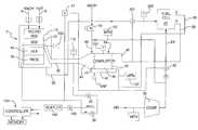
- FIG. 1is a schematic diagram of a fuel cell apparatus according to the present invention
- FIG. 2is a flow diagram depicting the combustor start-up control sequence according to the present invention
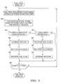
- FIG. 3is a flow diagram depicting the fuel processor warm-up combustor control sequence according to the present invention
- FIG. 4is a flow diagram depicting the fuel processor start-up combustor control sequence according to the present invention.
- FIG. 5is a flow diagram depicting the run mode combustor control sequence of the present invention.
- FIG. 6is a flow diagram of the combustor control shut down sequence according to the present invention.
- FIG. 7is a block flow diagram of a flow method according to the present inventionw
- the inventionis hereafter described in the context of a fuel cell fueled by a methanol (MeOH) fuel processor.
- MeOHmethanol
- the principles embodied hereinare equally applicable to fuel cells fueled by other fuels, such as ethanol or gasoline, which utilize a fuel processor for conversion into a hydrogen rich stream.
- a fuel cell apparatusincludes a fuel processor 2 for catalytically reacting methanol from a methanol stream 6 and water or steam from a water stream 8 in a recirculating bed 10 and a catalytic bed 12 to form a hydrogen-rich reformate gas stream.
- a heat exchanger 14is interposed between the catalytic bed 12 and a preferential oxidation (PROX) reactor 16 .
- the reformate output gas streamcomprises primarily H 2 and CO 2 , but also includes N 2 , CO and water.
- the reformate streampasses through the preferential oxidation (PrOx) reactor 16 to reduce the CO-levels therein to acceptable levels (i.e., below 20 ppm).
- the H 2 rich reformate 20is then fed into the anode chamber of a fuel cell 22 .
- oxygene.g., air
- the hydrogen from the reformate stream 20 and the oxygen from the oxidant stream 24react in the fuel cell 22 to produce electricity.
- Exhaust or effluent 26 from the anode side of the fuel cell 22contains some unreacted hydrogen.
- the exhaust or effluent 28 from the cathode side of the fuel cell 22contains some unreacted oxygen.
- the terms effluent and exhaustare used herein interchangeably.
- Air for the oxidant stream 24is provided by a compressor 30 and is directed to the fuel cell 22 by a valve 32 under normal operating conditions. During start-up, however, the valve 32 is actuated to provide air to the input of a combustor 34 used to heat the fuel processor 2 , as will be described in more detail hereinafter.
- Heat from the heat exchanger 14heats the catalyst bed(s) 10 and 12 in the fuel processor 2 and also heats the PROX 16 .
- the H 2 O—MeOH mixture supplied to the fuel processor 2will be vaporized and preferably be recirculated/refluxed several times (e.g., 20 ⁇ ) through the recirculating bed 10 in the fuel processor 2 , the heat exchanger side of the bed 12 , the PROX 16 and the heat exchanger 14 such that the mixture also functions as a heat transfer medium for carrying heat from the heat exchanger 14 into the beds 10 and 12 of the fuel processor 2 and to the PROX 16 .
- the heat exchanger 14itself is heated from exhaust gases 36 exiting the catalytic combustor 34 .
- the gases 36 exiting the heat exchanger 14are still hot and could be passed through an expander, not shown, which could drive the compressor 30 or utilized in another manner.
- the exhaust gases from the combustor 34are used to heat the fuel processor 2 pass through a regulator 38 , a shutoff valve 140 and a muffler 142 before being dumped to atmosphere.
- MeOH vapor 40emanates from a vaporizer 41 nested in the exhaust end 44 of the combustor 34 .
- the vaporizer 41is a heat exchanger that extracts heat from the combustor 34 exhaust to vaporize a first fuel stream, such as liquid MeOH 46 provided o the vaporizer 41 by fuel metering device 43 from the vehicle's fuel tank.
- the MeOH vapor 40 exiting the vaporizer 41 and the anode effluent 26are reacted in a catalyst section 48 of the combustor 34 lying intermediate the inlet and exhaust ends 42 and 44 respectively of the combustor 34 .
- Oxygenis provided to the combustor 34 either from the compressor 30 (i.e., via valve 32 ) or from a second air flow stream, such as a cathode effluent stream 28 depending on system operating conditions.
- a valve 50permits dumping of the combustor exhaust 36 to atmosphere when it is not needed in the fuel processor 2 .
- An electric heating element (EHC) 52is provided upstream of the catalyst bed 48 in the combustor 34 and serves to vaporize the liquid fuel 46 entering the combustor 34 , heat the gas entering the bed 48 as well as preheating the bed 48 during start-up of the combustor 34 .
- the heating element 52may or ray not be catalyzed. After start-up, as described hereafter, the electric heater 52 is no longer required since the fuel will be vaporized by the exhaust gases emanating from the exhaust end 44 of the combustor 34 .
- a preferred electric heater 52comprises a commercially available, uncatalyzed extruded metal monolith resistance element such as is used to light off the catalyst of a catalytic converter used to treat IC engine exhaust gases.
- the exhaust end 44 of the combustor 34includes a chamber that houses the vaporizer 41 which is a coil of metal tubing which is used to vaporize liquid fuel to fuel the combustor 34 . More specifically, under normal post-start-up conditions, air or cathode effluent 28 may be introduced into the inlet end of the coil and mixed with liquid fuel sprayed into the inlet end via a conventional automotive type fuel injector. The airborne atomized fuel passes through the several turns of the heated coil tube, and therein vaporizes and exits the tube at an outlet which is located in the cathode effluent supply conduit.
- This vaporized first fuel streamsupplements a second fuel stream or anode effluent 26 as fuel for the combustor 34 as may be needed to meet the transient and steady state needs of the fuel cell apparatus.
- the vaporizer coilis sized to vaporize the maximum flow rate of fuel with the minimum combustor exhaust flow rate, and is designed to operate at temperatures exceeding the autoignition temperature of the MeOH-air mixture therein throughout its fuel operational range. Autoignition within the vaporizer is avoided, however, by insuring that the velocity of the mix flowing through the coil significantly exceeds the worst-case flame speed of the mixture which varies with the composition of the inlet streams.
- the amount of heat demanded by the fuel processor 2 which is to be supplied by the combustor 34is dependent upon the amount of fuel and water input to the fuel processor 2 .
- the combustor 34utilizes all anode exhaust or effluent and potentially some liquid fuel. Enthalpy equations are used to determine the amount of cathode exhaust or air to be supplied to the combustor 34 to meet the desired temperature requirements of the combustor 34 , and the combustor 34 ultimately satisfies the heat demanded by the fuel processor 2 .
- the oxygen, air, or air like stream provided to the combustor 34includes one or both of cathode effluent exhaust 28 which is typically a percentage of the total oxygen supplied to the cathode of the fuel cell 22 and a compressor output air stream depending on whether the apparatus is operating in a start-up mode wherein the compressor air stream is exclusively employed or in a run mode using the cathode effluent 28 and/or compressor air.
- the run modeany total air, oxygen or diluent demand required by the combustor 34 which is not met by the cathode effluent 28 is supplied by the compressor 30 in an amount to balance the enthalpy equations, and to satisfy the temperature and heat demanded by the combustor 34 and the fuel processor 2 , respectively.
- the air quality controlis implemented via an air dilution valve 47 which is a stepper motor driven valve having a variable orifice to control the amount of bleed-off of cathode exhaust supplied to the combustor 34 and potentially the system exhaust, which bled-off air is dumped to atmosphere through the regulator 38 , the valve 140 , and the muffler 142 .
- a further description of the air dilution valve 47will be presented hereafter in conjunction with the various modes or sequences of operation of the combustor 34 .
- the fuel cell apparatus of the present inventionoperates as follows. At the beginning of operations when the fuel cell apparatus is cold and starting up: (1) the compressor 30 is driven by an electric motor energized from an external source (e.g., a battery) to provide the necessary system air; (2) air is introduced into the combustor 34 as well as the input end of the vaporizer 41 ; (3) liquid fuel 46 (e.g., MeOH) is injected into the inlet end of the vaporizer 41 via a fuel injector, and atomized as fine droplets with the air flowing therein; (4) the air-MeOH droplet mix exits the vaporizer 41 and mixes with compressor air introduced into the combustor 34 , and is then introduced into the input end 42 of the combustor 34 ; (5) the mix passes through a flame arrestor in the front of the combustor 34 ; (6) the mix is then heated by the heater 52 to vaporize the liquid droplets and heat the mixture; (7) the preheated vaporous mix then enters a mixing-media bed for
- valve 32is activated Ho direct air to the cathode side of the fuel cell 22 ;
- MeOH and waterare fed to the fuel processor 2 to commence the reformation reaction;
- reformate exiting the fuel processor 2is fed to the anode side of the fuel cell 22 ;
- anode effluent 26 from the fuel cell 22is directed into the combustor 34 ;
- cathode effluent 28 from the fuel cell 22is directed into the combustor 34 ;
- airis introduced into the vaporizer 41 ;
- liquid methanolis sprayed into the vaporizer 41 ;
- the methanol-air mixcirculates through the heated vaporizer coil where the MeOH vaporizes;
- (9) the methanol-air mix along with the cathode effluent 28then mixes with the anode effluent 26 ; and
- the mixis burned on the catalyst bed of the combustor 34 .
- the heater 52is not used as the vaporizer 41 alone vaporizes the MeOH and preheats the MeOH-air mix.
- the combustor 34could operate solely on the anode and cathode effluents, without the need for additional MeOH fuel from the vaporizer 41 . Under such conditions, MeOH injection to the combustor 34 is discontinued. Under other conditions, e.g., increasing power demands, supplemental fuel is provided to the combustor 34 .
- the combustor 34receives multiple fuels, such as a methanol-air mix as well as anode effluent 26 from the anode of the fuel cell 22 .
- Oxygen depleted exhaust air 28 from the cathode of the fuel cell 22 and air from the compressor 30are also supplied to the combustor 34 .
- a controller 150 shown in FIG. 1controls the operation of the combustor 34 .
- An enthalpy balancemaintains the desired reaction temperature by controlling the amount of air and/or cathode exhaust supplied to the combustor 34 to meet all fuel processor heat requirements.
- the controller 150may comprise any suitable microprocessor, microcontroller, personal computer, etc., which has central processing unit capable of executing a control program and data stored in a memory.
- the controller 150may be a dedicated controller specific to the combustor 34 or implemented in software stored in the main vehicle electronic control module. Further, although the following description describes a software based control program for controlling the combustor 34 in various modes of operation or sequence, it will also be understood that the combustor control can also be implemented in part or whole by dedicated electronic circuitry.
- the controller 150controls the operation of the combustor 34 in six different modes or sequences of operation.
- the separate modes of operationinclude (1) combustor start-up, (2) combustor operation during fuel processor warm-up, (3) combustor operation during fuel processor start-up, with the fuel cell off-line, (4) combustor operation during fuel processor run mode with the fuel cell stack on-line, and (5) combustor shut down.
- Each of these control sequenceswill be described with reference to the figures and to the equations in Table 1.
- FIG. 2there is depicted the sequence of program steps performed by the controller 150 to control the combustor 34 during a start-up mode or sequence.
- the controller 150 in step 152selects the start-up combustor power level and reaction temperature. These values are base on a particular combustor performance and overall system requirements for warm-up times since, at this point in the operation of the engine, the fuel processor 2 and the fuel cell 22 are inactive and there is no hydrogen available at start-up of the combustor 34 from the fuel cell 22 or from the fuel processor 2 .
- Other methodsinclude a quick start fuel processor and stack or on-board hydrogen or reformate storage.
- the controller 150switches the air bypass valve 32 to a position diverting all air output flow from the compressor 30 to the combustor 34 .
- the controller 150regulates the compressor 30 to provide the desired air flow to the combustor 34 for the selected power level and reaction temperature in step 154 .
- the controller 150also controls the orifice size of the stepper motor, as described hereinafter, driven air dilution valve 47 to provide selected bleed-off of the air supplied to the combustor 34 in order to balance the enthalpy of the reaction in the combustor 34 by determining the amount of air flow required in the combustor 34 to create a desired reaction temperature within the combustor given the heat requirements demanded by the fuel processor 2 .
- controller 150uses equations 1, 2, and 16 in Table 1 to determine the desired methanol flow and air flow required to obtain the combustor reaction temperature calculated using equations 4-15 in Table 1.
- the controller 150 in step 156then compares the air flow to the compressor 30 as measured by a mass flow meter with a minimum combustor air flow. If the measured air flow is less than the preset minimum combustor air flow, the controller 150 enters a timeout loop in step 158 which sets a time limit for the combustor 34 to reach the desired air flow level. If time expires in the timeout loop in step 156 , the controller 150 switches to a combustor shutdown sequence described hereafter.
- the controller 150 in step 160checks a sensor or thermocouple 151 to determine the temperature of the catalyst bed 48 in the combustor 34 . If the temperature of the bed 48 exceeds the heater 52 preset turnoff temperature, the controller 150 turns off the heater 52 in step 162 . If the temperature of the bed in step 160 is less than the heater turnoff temperature, the controller 150 turns on the heater in step 164 .
- step 166the controller 150 determines the vaporizer air flow from the output of a mass flow meter 167 and compares the measured air flow with a minimum air flow set point. If the measured vaporizer air flow is less than the set point, the combustor shutdown sequence is executed. However, if the vaporizer air flow is above the minimum air flow set point, the controller 150 next determines if the temperature of the catalyst bed 48 in the combustor 34 , as measured by sensor 151 , exceeds a minimum temperature set point. If the temperature of the bed is less than the minimum temperature set point, a timeout loop in step 170 is executed which routes control back through steps 160 - 168 as long as time remains in the timeout period. Eventually, if the timeout period in the timeout loop in step 170 is exceeded and the temperature of the combustor bed has not reached the set point temperature, the controller 150 executes the combustor shutdown sequence.
- the controller 150When the measured temperature of the combustor bed 48 equals or exceeds the minimum set point temperature, the controller 150 turn the methanol fuel flow on via fuel injector 43 at a desired combustion power level as set in step 172 .
- the controller 150then measures the vaporizer 41 temperature in step 174 from sensor Tvap and compares the measured vaporizer temperature with a set point temperature for running the combustor 34 at full power. If the vaporizer temperature is less than the set point run temperature, a timeout loop 176 is entered to allow time for the vaporizer temperature to come up to set point. Eventually, if the timeout: period is exceeded without a temperature match, the combustor shutdown sequence is executed.
- step 180the controller 150 sets the combustor power level and reaction temperature based on the system requirements for warming up the fuel processor 2 to a preset temperature. If stored hydrogen is not available, all of the combustor power comes from the liquid fuel.
- the controller 150uses equations, 1, 2, and 16 to calculate the methanol flow.
- the air flow required to obtain the desired combustor reaction temperatureis calculated by the controller 150 in step 182 using equations 4-15 and controlled by the air dilution valve 47 .
- the controller 150uses feedback from the fuel processor 2 then determines in step 184 if the output power of the combustor 34 is desired to be increased. If not so desired, then in step 185 it is determined whether combustor power is decreasing. If not, the fuel processor is started at step 198 . If combustor power is decreasing, then proceed to step 192 .
- step 186the controller 150 increases the air flow to the combustor 34 in step 186 and then waits in step 188 for the air flow to increase as measured by a change in the combustor exhaust temperature from a sensor or thermocouple 116 .
- This wait periodcan be a programmed time delay, or a period based on feedback from either an air flow meter, a temperature decrease in the combustor catalyst bed, or a pressure increase in the combustor manifold.
- the controller 150then increases the methanol flow to the combustor 34 in step 190 .
- the controller 150determines that the combustor power is decreasing in step 185 , the controller 150 decreases the methanol flow to the combustor 34 in step 192 .
- Another await period 194is executed for the fuel flow to decrease to the set amount. This wait period can be a programmed time delay, or based on feedback from either a methanol flow meter, a temperature decrease in the combustor catalyst bed, or a pressure decrease in the combustor manifold.
- the controller 150 in step 196decreases the air flow to the combustor 34 for proper reaction power and temperature.
- step 185the controller 150 determines in step 108 if the fuel processor 2 is ready for start-up. If not, steps 180 through 196 are re-executed as described above until the fuel processor 2 is ready for start-up.
- a change in air flowleads a change in fuel flow when power is increasing and a change in fuel flow leads a change in air flow when power is decreasing.
- step 200the fuel processor requirements, such as the operating temperature of the fuel processor catalyst and the desired fuel processor output power (equivalent kilowatts of hydrogen production), are used to determine the combustor power and reaction temperature required to meet the system requirements to start-up the fuel processor 2 to a steady state run temperature.
- the fuel processor 2is operated at an output (hydrogen/effluent production) level that the combustor 34 can consume.
- the entire output of the fuel processor 2is recirculated to the combustor 34 as fuel through a fuel bypass valve 201 which supplies the fuel processor output gas stream to a second inlet on the combustor 34 .
- Bypass airis also supplied to the combustor 34 through air bypass valve 32 to cause combustion of the reformate from the fuel processor 2 .
- valve 32is a proportional air bypass valve.
- the total amount of air from the compressor 30 supplied to the combustor 34is regulated by one or more of the following: variable compressor speed; the position of the proportional air bypass valve 32 ; and the diameter of the air dilution valve 47 ; or the position of valve 47 .
- the output flow of valve 47is preferably adjusted by controlling the diameter of an output flow orifice of valve 47 .
- the air supplied to the combustoris also controllable by changing the position of valve 32 in the valve body from open to closed or to an intermediate position such as partially open or partially closed. In that regard, equations 1-16 are useful.
- the amount of hydrogen in the reformate stream which is supplied to the combustor 34is calculated by the controller 150 in step 202 based on a given amount of fuel and water injected into the fuel processor 2 which react to make a given amount of hydrogen, carbon monoxide, carbon dioxide and water.
- the controller 150also takes into account the injection of a certain amount of air into the PrOx reactor 16 and, based on the amount of air input to the PrOx reactor 16 , a determination is made of how much hydrogen generated by the fuel processor 2 is consumed by the PrOx 16 . From these calculations, the controller 150 determines the equivalent power (i.e., hydrogen) output from the fuel processor 2 .
- the controller 150compares the calculated or determined hydrogen quantity generated by the fuel processor 2 and supplied to the combustor 34 with the calculated fuel processor start-up power and reaction temperature requirements, taking into account heat generated by the PrOx 16 , and, in step 204 , calculates the supplemental amount of methanol and oxidant stream flow rates to the combustor using equations 1-16 in Table 1, with the diameter of the orifice of the air dilution valve 47 controlled to balance the enthalpy of the combustor reaction. For example, assuming that, on start-up, the fuel processor 2 produces 30 kilowatts equivalent of hydrogen which is supplied to the combustor 34 .
- Equations 1-16are solved to determine how much air is required to generate a desired gas stream temperature at this amount of power.
- the control programinsures that the maximum power possible is obtained first from the output of the fuel processor 2 , including any heat generated by the PrOx 16 , before additional quantities of methanol are used.
- the fuel processor warm-up and fuel processor start-up control sequences for the combustor 34can be utilized from an initial cold start of the fuel cell apparatus where the engine has been sitting idle for a long period of time and has reached ambient temperature or employed when the engine has been turned off only for a short period of time such that residual heat remains in the fuel processor and combustor catalyst beds.
- the fuel processor 2could generate acceptable levels of reformate, e.g., low amounts of carbon monoxide, from the start.
- step 206the controller 150 checks if the hydrogen level supply to the combustor 34 exceeds the fuel processor heat requirement or the combustor maximum design power output. If there is excess hydrogen, the controller 150 switches to the combustor shutdown sequence. Alternatively, the fuel processor power could be reduced. If there is not excess hydrogen in step 206 , a determination is made in step 208 if there is a sufficient quantity of hydrogen supplied from the fuel processor 2 to the combustor 34 . If there is insufficient hydrogen, the controller 150 in step 210 calculates the supplemental amount of methanol required to obtain the desired fuel processor temperature. Again, maximum power is obtained first from the output of the fuel processor 2 and then from methanol.
- the controllerexecutes equations 1-3 and 16 in Table 1. Based on the calculated values in step 210 , the controller 150 adjusts the air flow to the combustor 34 by changing the cross section of the orifice of the valve 47 in step 212 , waits for the desired air flow change, and then increases liquid methanol fuel flow in step 214 to the combustor 34 . The controller 150 adjusts the fuel flow rate in step 214 using the equations in Table 1 based on the fuel energy content.
- step 218the controller 150 determines if the combustor power output is greater than the fuel processor power requirement. If the answer is no, the controller 150 checks in step 220 if the system is ready to enter a run mode for fuel cell operation. If not, control switches back to step 200 and steps 200 - 220 are re-executed.
- step 222open s the combustion exhaust diverter valve 50 to divert or dump combustor exhaust to atmosphere.
- the controller in step 224determines if there is methanol fuel flow to the combustor 34 . If the answer is yes, the controller 150 in step 226 decreases the amount of the liquid fuel flow to the combustor 34 to a level required to meet fuel processor combustion power requirements.
- a wait periodis executed in step 228 for a fuel flow is change, which can be a programmed time delay, or based on feedback from a fuel flow meter, or a temperature decrease in the combustor catalyst bed, or a pressure decrease in the combustor manifold. Steps 216 - 222 are then executed as described above.
- FIG. 5depicts the run mode or sequence of operation of the combustor 34 when the fuel processor 2 is in a run mode.
- the system developed equationsare used to calculate the compositions of the anode exhaust streams and the cathode exhaust streams from the fuel cell 22 which are supplied to the combustor 34 as described above.
- the required fuel processor power and reaction temperaturesare used to calculate the methanol fuel flow rate and cathode exhaust flow rate to the combustor 34 using the anode exhaust flow rate and composition and the cathode stream composition. Equations 1-16 in Table 1 are used to maintain an enthalpy balance of the reaction by controlling the oxidant stream via regulating the orifice diameter of the air dilution valve 47 and/or the compressor speed.
- the fuel processor temperatureis checked in step 234 , via the output of a temperature sensor thermocouple 235 located between the output of the heat exchanger 14 and the plug flow bed 12 within the fuel processor 2 , to determine if it is below a steady state run temperature. If the fuel processor temperature is low, the controller 150 in step 236 increases the combustor output power and recalculates air and fuel flow to the combustor 34 to raise the fuel processor 2 temperature to the steady state set point. In order to increase the combustor power, the controller 150 in step 238 increases the air flow by adjusting the orifice diameter of valve 47 and waits in step 240 for the desired change in the air flow to take effect.
- the wait periodcan be a programmed time delay, or based on feedback from the air flow meter, a temperature decrease in the combustor catalyst bed, or a pressure increase in the combustor manifold.
- the controller 150increases the methanol fuel flow to the combustor 34 in step 242 .
- step 234determines if the fuel processor steady state temperature is high or exceeds the desired steady state temperature in step 244 . If the fuel processor temperature as determined in step 244 is higher than the set point, the controller 150 then determines in step 246 if the methanol fuel flow is turned on to the combustor 34 . If the liquid fuel flow is not on, the controller 150 activates the exhaust dump valve 50 .
- the controller 150decreases combustor power in step 248 and recalculates the desired methanol fuel flow and air flow to the combustor 34 using the enthalpy balance equations 1-16 in Table 1.
- the controller 150then decreases methanol fuel flow to the combustor 34 in step 250 and waits a predetermined time for a change in the fuel flow in step 252 .
- the wait periodcan be a programmed time delay, or based on feedback from the fuel flow meter, a temperature decrease in the combustor catalyst bed, or a pressure decrease in the combustor manifold.
- the controller 150then adjusts the air flow to the combustor 34 for the decreased liquid fuel flow rate.
- the controller 150determines if the system is to remain in a continuous run mode and, if so, control switches back to step 230 . If system operation is not to be continued, the controller 150 enters a shutdown sequence as described hereafter and shown in FIG. 6 .
- the control sequence for shutting down the combustor 34is initiated by a shutdown command or when the controller 150 reaches a shutdown sequence as shown in FIG. 6 .
- the sequencebegins at step 259 where the shutdown command initiates the turning off of liquid fuel to the combustor.
- step 260 shown in FIG. 6the controller 150 determines if the fuel processor fuel supply is turned off. If it is, the controller 150 in step 262 sets the air flow to the combustor 34 to a preset shutdown flow rate.
- step 264the controller 150 determines if the combustor 34 has reached a preset shutdown temperature. If not, the controller 150 executes a wait period 266 and loops through steps 264 and 266 until the combustor temperature has reached its desired shutdown temperature. The controller 150 then shuts off air flow to the combustor 34 in step 268 to complete the combustor shutdown sequence.
- step 270determines the remaining energy and composition by calculating the anode and cathode exhaust compositions from the fuel cell 22 .
- step 272the controller 150 calculates the cathode flow rate and oxidant flow rate from the fuel cell 22 required for the combustor 34 to consume all of the remaining fuel in the apparatus.
- the controller 150then adjusts the air flow rate to the combustor 34 in step 274 via air valve 47 as required by the results of step 272 and returns to step 260 until all of the fuel remaining in the apparatus has been consumed. It should be noted that if the energy content remaining in the apparatus is high, the controller 150 may cause the combustor 34 to exhaust the remaining fuel content energy through the system dump valve 50 .
- FIG. 7there is depicted a control method used to control the effective or cross sectional area of the orifice of the air valve 47 , as described above, to control the air flow rate and the oxygen quantity to the combustor 34 .
- control methodcan be implemented in either hardware elements or, preferably, software via a control program stored in the memory of the electronic control module of the fuel cell apparatus.
- control method of the present inventionutilizes a feed forward control which quickly sets the effective or cross sectional opening of the orifice of air dilution valve 47 for a predetermined air flow rate based on the nitrogen, oxygen and water molar constituents of the air, including atmospheric air and fuel cell cathode effluent which generally is depleted oxygen air, the partial pressures of the constituents of atmospheric air and the expected output of cathode effluent of the fuel cell, as well as a table of valve cross-sectional orifice area versus opening size in a number of discrete steps.
- a conventional PID feedback loopis used to implement the final setting of the orifice diameter of the air dilution control valve 47 .
- a combustor air valve math model 300is implemented by a control program executed by the ECM of the fuel cell apparatus.
- the math model 300receives inputs 302 , 304 and 306 representing the mole constituents of oxygen, nitrogen and water, respectively, in the cathode effluent of the fuel cell. These molar constituents can be calculated in a separate processor in the fuel cell apparatus or in the ECM which contains the math model 300 (FIG. 7) and by example are: 10% for O 2 , 75% for N 2 and 15% for H 2 O.
- Also input to the math model 300are the partial pressures of the mole fractions of oxygen 308 , nitrogen 310 and water 312 in the cathode effluent from the fuel cell. Again, these values are calculated based on the expected cathode effluent constituent make-up of the fuel cell during normal run mode and each other mode of operation of the fuel cell apparatus.
- Sensor inputs to the math model 300include the cathode effluent pressure 314 upstream of valve 47 , the pressure 316 downstream of the valve 47 and the cathode effluent temperature 318 upstream of valve 47 . These input values are measured by conventional pressure and temperature sensors placed at appropriate locations in the cathode effluent flow line.
- K_COMB_AIR_VLV_K_CONSTANT 322is input to the math model 300 to provide an indication of the flow characteristics of the orifice between full open and full closed. For the present example, this constant was 2.0.
- the K —COMB —AIR —VLV —K _CONSTANTcan also be obtained from a look-up table if the constant changes with valve position.
- the combustorreceives either atmospheric air from the compressor 30 or cathode effluent from the fuel cell 22 . Based in the particular fuel cell stoichiometry, excess air, typically on the order of double the amount normally required, is supplied to the fuel cell to support fuel cell operation. It is conceivable that different fuel cells may have different cathode stoichiometries such that the amount of oxygen contained in the cathode effluent may be so low as to require air from the compressor to support combustor operation in the run mode.
- the math model 300uses two sets of molar constituents and mole fraction partial pressures.
- One setis for normal atmospheric air supplied by the compressor during combustor start-up, fuel processor warm-up and fuel processor start-up modes described above.
- a second modelis used to determine values 302 to 312 and supply them to the model 300 , shown in FIG. 7 .
- a particular fuel processor outputwill be calculated.
- a combustor output heat requirementwill then be determined to support the required fuel processor operating temperature.
- Solution of enthalpy balance equationsprovides a desired air flow to the combustor 34 to support combustor operation in supplying the required fuel processor heat requirements.
- any conventional air dilution valve 47 having a variable cross section orificemay be employed in the present control method.
- a stepper motor controlled air dilution valve 47is preferred due to precise discrete steps of orifice cross section.
- the orifice shapemay be any conventional orifice shape, including a knife edge orifice, a tube orifice, or an orifice with round edges. etc.
- a v( ( A u 2 ) ⁇ ( k ) ⁇ ( m / 1000 ) 2 [ ( P u - P d ) ⁇ ( 1000 ) ] ⁇ ( 2 ) ⁇ ⁇ mix ) ⁇ ( A u ) 2 + ( 0.5 ) ⁇ ( m / 1000 ) 2 ) ⁇ ( 1 ⁇ 10 6 )
- a vValve ⁇ ⁇ Area ⁇ ⁇ Desired ⁇ ⁇ ( m 2 ⁇ / ⁇ 1 ⁇ 10 6 , for ⁇ ⁇ mm 2 )
- the math model 300generates an output 331 labeled COMB_AIR_VLV_POS_DES_VIRTUAL which is used to generate a command position signal 332 specifying a step number for the stepper motor of the air dilution valve 47 which adjusts the orifice cross section to provide the desired air flow rate to the combustor 34 .
- the manufacturer of each valve 47will supply orifice cross sectional area versus stepper motor steps as part of the design data of the stepper motor operated valve 47 .
- This datais stored in memory in the math model 300 as a lookup table wherein the desired valve area (Av), as calculated above, acts as an address to the lookup table, the output of which is the number of steps for the stepper motor to adjust the orifice of the valve for the desired air flow.
- the output 331 from the math model 300is the determined valve step number.
- the fast response of the math model 300results in a fast repositioning of the valve orifice cross section so as to make the valve orifice cross-sectional changes quickly in response to variable load changes on the fuel cell 22 , fuel processor 2 , and combustor 34 .
- command position signal 332 specifying a desired orifice cross-sectional area in the valve 47may be the exact cross-sectional area required to support a desired air flow to the combustor 34 , it is possible, and probably typical, due to valve tolerances, fuel cell operation variations, etc., for the actual air flow to the combustor 34 , as measured by the mass flow meter 157 , to vary from the desired or calculated predetermined air flow rate.
- the output 331 from the math model 300is considered an initial set point for the air dilution valve orifice cross section, but a set point which is quickly achieved due( to the feed forward structure of the math model 300 .
- any error between the actual flow rate and the predetermined or calculated air flow rateis determined in step 340 .
- This erroris supplied to a feedback loop 342 to generate signals to the stepper motor of the valve 47 to make fine changes in the cross-sectional area of the orifice to reduce the error to zero.
- any control feedbackmay be employed which compares a set point or actual desired air flow rate with a measured air flow rate to develop an error signal, with the error signal used to adjust the cross sectional area of the orifice of the valve 47 to reduce the error signal to zero
- a PID control loopshown in FIG. 7 is preferred.
- the PID loop 342includes proportional, integral and derivative terms 344 , 346 and 348 , respectively, which are added to or subtracted from the error signal to develop the desired output control signal. More specifically, the D term has two parts, 348 and 350 , which is designated as 349 .
- PID control loopsmay be implemented in either hardware or software.
- the PID terms 344 , 346 and 349may be provided by separate amplifier, integrator and differentiator circuits. Alternately, and preferred in the present invention, these terms are used in a software implementation of the ECM by a conventional algorithm to generate values for the control signal in response to applied values for measurement and set point inputs of the orifice cross-sectional area.
- the proportional term 344represents a linear gain factor related to the magnitude of the error signal and the magnitude of the control signal necessary to achieve the desired orifice cross-sectional area.
- the integral term 346is a long time constant linear gain term related to the integral of the error signal used to reduce to the residual error that would otherwise occur in a proportional only control loop between the set point and measured air flow values.
- the derivative term 349is the derivative of the error signal and enhances system response to short term transients without reducing the long term accuracy benefits of the integral term.
- the outputs of the multipliers 350 and 344 and the integral term 346are summed in a summing junction 352 along with a K_COMB MAF_TRIM_LOOP_BIAS gain term 354 .
- This calibration or gain term 354defines the default position of the valve 47 when no error exists between the actual air flow to the combustor 34 and the predetermined desired air flow to the combustor 34 .
- the calibration term 354inputs a number into the FID control loop 342 , preferably into the summing junction 352 . In one aspect, the calibration term 354 inputs a number into the PID control loop 342 when the outputs of the proportional, integral and derivative terms 344 , 346 and 349 are zero.
- the output of the summing junction 352is input to a scaler or divider 356 which divides the summer output by 100 .
- the output of the scaler 356is adjusted by K_COMB_MAF_TRIM_ADJ_MIN and K_COMB MAF_TRIM_ADJ_MAX constants which define the minimum and maximum limits for the error signal adjustment signal. In general, these limits stop the integrator 346 from Charging up or charging down too far.
- the output of the divider 356is summed in step 330 with the output 331 of the math model 300 .
- the cross-sectional area of the orifice of the air dilution valve 47will be quickly adjusted to the command position set by the output 331 of the math model 300 and then more slowly adjusted by the PID loop 342 to eliminate any error between the actual air flow to the combustor 34 as measured by the mass flow meter 157 and the desired or predetermined air flow to the combustor 34 as established by the enthalpy balance equations described above.
- a unique combustor air flow control methodwhich provides quick response in establishing a predetermined air flow to the combustor over varying power requirements imposed on the combustor.
- the control methodapplies a feed forward control output with a conventional FID control loop error output to precisely control the cross-sectional area of the orifice of the air dilution valve to control the air flow to the combustor.
- the present control methodologyalso compensates for molar fraction deviations of oxygen depleted air in the cathode effluent from the fuel cell to support the desired heat output of the combustor.
- dh(MeOH)H(MeOH, T MeOH ) ⁇ H(CO 2 , T CRT ) ⁇ 2 ⁇ H(H 2 O, T CRT ) + 1.5 ⁇ , H(O 2 ⁇ T CRT )
- H(X, T y )enthalpy of component X at temperature T y
- T MeOHtemperature of liquid MeOH supplied to vaporizer
- T CRTcombustor reaction temperature (combustion out temperature)
- dh(CO 2 )H(CO 2 , Tan) ⁇ H(CO 2 , T CRT )
- Tananode temperature into combustor (7)
- dh(H 2 )H(H 2 , Tan) + 0.5 ⁇ H(O 2 , T CRT ) ⁇ H(H 2 O, T CRT )
- dh(H 2 O)H(H 2 O, Tan) ⁇ H(H 2 O, T CRT ) (9)
- dh(CATH O 2 )H(O 2 , T CA ) ⁇ H(O 2 , T CRT )
- T CACathode Input Temperature
- dh(CATH N 2 )H(N 2 , T CA ) ⁇ H(N 2 , T CRT )
- dh(CATH H 2 O)H(H 2 O, T CA ) ⁇ H(H 2 O, T CRT )
Landscapes
- Chemical & Material Sciences (AREA)
- Engineering & Computer Science (AREA)
- Organic Chemistry (AREA)
- Chemical Kinetics & Catalysis (AREA)
- Sustainable Development (AREA)
- Sustainable Energy (AREA)
- Life Sciences & Earth Sciences (AREA)
- Electrochemistry (AREA)
- General Chemical & Material Sciences (AREA)
- Health & Medical Sciences (AREA)
- General Health & Medical Sciences (AREA)
- Combustion & Propulsion (AREA)
- Inorganic Chemistry (AREA)
- Manufacturing & Machinery (AREA)
- Fuel Cell (AREA)
Abstract
Description

| TABLE 1 |
| Operating Equations |
| (1) | PC= PMeOH+ PH2(KW) | ||
| where: PC= combustor power, PMeOH= | |||
| power from MeOH, PH2= power from hydrogen | |||
| (2) | PMeOH= 636 nMeOH | ||
| where: nMeOH= molar flow of MeOH | |||
| (3) | PH2= 242 nH2 | ||
| where: nH2= molar flow of hydrogen | |||
| (4) | nCATH= (nMeOH· dh(MeOH) + nCO2· | ||
| dh(CO2) + nH2· dh(H2) + | |||
| nH2O · dh(H2O) + nN2· | |||
| dh(N2))/dh(CATH) | |||
| where: nCATH= molar flow of cathode input to | |||
| combustor; nCO2, nH2, nH2O, nN2= molar | |||
| flows of CO2, H2, H2O, and N2, | |||
| respectively, in the anode input to the | |||
| combustor; dh(X) = difference of the | |||
| enthalpy for given component X from inlet | |||
| of combustor to outlet of combustor. | |||
| (5) | dh(MeOH) = H(MeOH, TMeOH) − H(CO2, TCRT) − | ||
| 2 · H(H2O, TCRT) + 1.5 · , | |||
| H(O2− TCRT) | |||
| where: H(X, Ty) = enthalpy of component X at | |||
| temperature Ty, TMeOH= temperature of | |||
| liquid MeOH supplied to vaporizer, TCRT= | |||
| combustor reaction temperature (combustion | |||
| out temperature) | |||
| (6) | dh(CO2) = H(CO2, Tan) − H(CO2, TCRT) | ||
| where: Tan = anode temperature into combustor | |||
| (7) | dh(H2) = H(H2, Tan) + 0.5 · H(O2, | ||
| TCRT) − H(H2O, TCRT) | |||
| (8) | dh(H2O) = H(H2O, Tan) − H(H2O, TCRT) | ||
| (9) | dh(N2) = H(N2, Tan) − H(N2, TCRT) | ||
| (10) | dh(CATH) = % O2· dh(CATH O2) + | ||
| % N2· dh(CATH N2) + | |||
| % H2O · dh(CATH H2O) | |||
| where: % O2, % N2and % H2O are mole fractions | |||
| (percentages) of oxygen, nitrogen and | |||
| water, respectively, in the cathode input. | |||
| (11) | dh(CATH O2) = H(O2, TCA) − | ||
| H(O2, TCRT) | |||
| where: TCA= Cathode Input Temperature | |||
| (12) | dh(CATH N2) = H(N2, TCA) − | ||
| H(N2, TCRT) | |||
| (13) | dh(CATH H2O) = H(H2O, TCA) − | ||
| H(H2O, TCRT) | |||
| (14) | mCATH= nCATH· mwCATH | ||
| where: mwCATH= molecular weight of cathode input | |||
| stream | |||
| (15) | mwCATH= % O2· mwO2+ % N2· mwN2+ | ||
| % H2O · mwH2O | |||
| (16) | mMeoH= nMe0H· mwMeoH | ||
Claims (14)
Priority Applications (4)
| Application Number | Priority Date | Filing Date | Title |
|---|---|---|---|
| US09/565,781US6306531B1 (en) | 1999-07-06 | 2000-05-05 | Combustor air flow control method for fuel cell apparatus |
| CA002310440ACA2310440A1 (en) | 1999-07-06 | 2000-06-01 | Combustor air flow control method for fuel cell apparatus |
| EP00112073AEP1069637A3 (en) | 1999-07-06 | 2000-06-05 | Combustor air flow control method for fuel cell apparatus |
| JP2000202313AJP2001023669A (en) | 1999-07-06 | 2000-07-04 | Combustor airflow control method for fuel cell device |
Applications Claiming Priority (2)
| Application Number | Priority Date | Filing Date | Title |
|---|---|---|---|
| US34512799A | 1999-07-06 | 1999-07-06 | |
| US09/565,781US6306531B1 (en) | 1999-07-06 | 2000-05-05 | Combustor air flow control method for fuel cell apparatus |
Related Parent Applications (1)
| Application Number | Title | Priority Date | Filing Date |
|---|---|---|---|
| US34512799AContinuation-In-Part | 1999-07-06 | 1999-07-06 |
Publications (1)
| Publication Number | Publication Date |
|---|---|
| US6306531B1true US6306531B1 (en) | 2001-10-23 |
Family
ID=26994266
Family Applications (1)
| Application Number | Title | Priority Date | Filing Date |
|---|---|---|---|
| US09/565,781Expired - LifetimeUS6306531B1 (en) | 1999-07-06 | 2000-05-05 | Combustor air flow control method for fuel cell apparatus |
Country Status (4)
| Country | Link |
|---|---|
| US (1) | US6306531B1 (en) |
| EP (1) | EP1069637A3 (en) |
| JP (1) | JP2001023669A (en) |
| CA (1) | CA2310440A1 (en) |
Cited By (37)
| Publication number | Priority date | Publication date | Assignee | Title |
|---|---|---|---|---|
| US20020106544A1 (en)* | 2001-02-07 | 2002-08-08 | Noetzel John G. | Solid oxide auxiliary power unit reformate control |
| US20030003332A1 (en)* | 2001-06-28 | 2003-01-02 | Ballard Power Systems Inc. | Self-inerting fuel processing system |
| US20030062205A1 (en)* | 2001-09-28 | 2003-04-03 | Daimlerchrysler Ag | Vehicle featuring a main drive engine, a compressor and a current source and method for operating the vehicle |
| US6572993B2 (en)* | 2000-12-20 | 2003-06-03 | Visteon Global Technologies, Inc. | Fuel cell systems with controlled anode exhaust |
| WO2003060380A1 (en)* | 2002-01-11 | 2003-07-24 | General Motors Corporation | Quick start large dynamic range combustor configuration |
| US6627340B1 (en)* | 1999-11-06 | 2003-09-30 | Energy Conversion Devices, Inc. | Fuel cell hydrogen supply systems using secondary fuel to release stored hydrogen |
| US6641944B2 (en)* | 2000-10-12 | 2003-11-04 | Nissan Motor Co., Ltd. | Fuel cell drive system |
| US6653004B1 (en)* | 1999-10-12 | 2003-11-25 | Jeffrey Lewis Barber | Process control for multiple air supplies |
| US20030226399A1 (en)* | 2002-06-06 | 2003-12-11 | Clingerman Bruce J. | Diagnostic system for identifying fuel injector failure in a fuel cell system |
| US20030235732A1 (en)* | 2002-06-24 | 2003-12-25 | Haltiner Karl J. | Solid-oxide fuel cell system having means for controlling tail gas combustion temperature |
| US6670061B2 (en)* | 2000-12-04 | 2003-12-30 | Nissan Motor Co., Ltd. | Fuel cell power plant |
| US20040013913A1 (en)* | 2002-07-16 | 2004-01-22 | Siemens Westinghouse Power Corporation | Method and system for controlling the operating temperature of a fuel cell |
| US6759156B1 (en)* | 2003-04-04 | 2004-07-06 | Texaco Inc. | Operating states for fuel processor subsystems |
| US6796332B1 (en)* | 2003-04-04 | 2004-09-28 | Texaco Inc | Fluid balance control system for use in a fuel processor |
| US20040229092A1 (en)* | 2002-11-11 | 2004-11-18 | Nippon Telegraph And Telephone Corporation | Fuel cell power generating system with two fuel cells of different types and method of controlling the same |
| US20050079462A1 (en)* | 2003-10-08 | 2005-04-14 | Sennoun Mohammed E. H. | Premixed prevaporized combustor |
| US20060292410A1 (en)* | 2005-06-28 | 2006-12-28 | Andreas Kaupert | Fuel cell system for a vehicle |
| WO2007021351A1 (en)* | 2005-08-09 | 2007-02-22 | Exxonmobil Upstream Research Company | Natural gas liquefaction process for lng |
| US20070128485A1 (en)* | 2005-12-02 | 2007-06-07 | General Electric Company | Fuel cell system |
| US20070248859A1 (en)* | 2006-04-21 | 2007-10-25 | Penev Michael M | Recuperative exhaust gas processor for a fuel cell system |
| US20080113232A1 (en)* | 2004-10-26 | 2008-05-15 | Masataka Ozeki | Fuel Cell System |
| US20100167098A1 (en)* | 2008-12-26 | 2010-07-01 | Yamaha Hatsudoki Kabushiki Kaisha | Fuel cell system and transportation equipment including the same |
| US20100221621A1 (en)* | 2007-10-23 | 2010-09-02 | Honda Motor Co., Ltd. | Operation method at the time of load reduction of fuel cell system |
| US20100239926A1 (en)* | 2006-06-22 | 2010-09-23 | Wärtsilä Finland Oy | Preheating arrangement in a fuel cell apparatus |
| US20110189573A1 (en)* | 2010-02-03 | 2011-08-04 | Gm Global Technology Operations, Inc. | Online anode pressure bias to maximize bleed velocity while meeting emission constraint |
| US8614023B2 (en) | 2009-02-06 | 2013-12-24 | Protonex Technology Corporation | Solid oxide fuel cell systems with hot zones having improved reactant distribution |
| CN104051756A (en)* | 2013-03-15 | 2014-09-17 | 通用汽车环球科技运作有限责任公司 | Fcs overall efficiency by using stored cathode oxygen during down-transients |
| EP2982644A4 (en)* | 2013-04-05 | 2016-04-20 | Panasonic Ip Man Co Ltd | HYDROGEN GENERATING DEVICE |
| CN104051756B (en)* | 2013-03-15 | 2016-11-30 | 通用汽车环球科技运作有限责任公司 | By using the cathode oxygen stored to improve the overall efficiency of fuel cell system during power temporarily declines |
| WO2018146172A1 (en)* | 2017-02-09 | 2018-08-16 | Avl List Gmbh | Ignition burner for a fuel cell system |
| US10109867B2 (en) | 2013-06-26 | 2018-10-23 | Upstart Power, Inc. | Solid oxide fuel cell with flexible fuel rod support structure |
| US10573911B2 (en) | 2015-10-20 | 2020-02-25 | Upstart Power, Inc. | SOFC system formed with multiple thermally conductive pathways |
| US10665885B2 (en)* | 2017-04-10 | 2020-05-26 | Toyota Jidosha Kabushiki Kaisha | Vehicle with fuel cell unit |
| US10790523B2 (en) | 2015-10-20 | 2020-09-29 | Upstart Power, Inc. | CPOX reactor control system and method |
| US11108072B2 (en) | 2016-08-11 | 2021-08-31 | Upstart Power, Inc. | Planar solid oxide fuel unit cell and stack |
| US11784331B2 (en) | 2014-10-07 | 2023-10-10 | Upstart Power, Inc. | SOFC-conduction |
| US12374709B2 (en) | 2019-08-14 | 2025-07-29 | Upstart Power, Inc. | Sofc-conduction |
Families Citing this family (13)
| Publication number | Priority date | Publication date | Assignee | Title |
|---|---|---|---|---|
| US6716400B2 (en)* | 2001-03-09 | 2004-04-06 | Honda Giken Kogyo Kabushiki Kaisha | Ignition system for a fuel cell hydrogen generator |
| JP3700603B2 (en) | 2001-04-06 | 2005-09-28 | 日産自動車株式会社 | Fuel cell system |
| JP3693291B2 (en)* | 2001-05-15 | 2005-09-07 | 本田技研工業株式会社 | Raw fuel evaporation apparatus, raw fuel evaporation method, and fuel cell system including raw fuel evaporation apparatus |
| FR2842355B1 (en)* | 2002-07-09 | 2008-04-04 | Renault Sa | ELECTRICITY GENERATING SYSTEM USING A FUEL CELL AND METHOD OF OPERATING A FUEL CELL |
| EP1466864A3 (en)* | 2003-04-09 | 2004-12-29 | Forni-Tecnica S.r.l. | Method, system and plant for regulating a gas generator |
| FR2858046A1 (en)* | 2003-07-25 | 2005-01-28 | Renault Sa | Device for controlling quantity of air injected to catalytic burner of fuel cell system mounted on motor vehicle to minimize fuel consumption and carbon monoxide emission |
| JP2005071636A (en)* | 2003-08-27 | 2005-03-17 | Nissan Motor Co Ltd | Stop control device for fuel cell system |
| JP4584564B2 (en)* | 2003-10-10 | 2010-11-24 | 日産自動車株式会社 | Fuel cell exhaust system |
| JP4649936B2 (en)* | 2004-10-04 | 2011-03-16 | 日産自動車株式会社 | Fuel cell system |
| CN111971127B (en)* | 2018-04-11 | 2022-06-24 | 株式会社岛津制作所 | Field flow separation device |
| CN113632269B (en)* | 2019-03-27 | 2024-02-27 | 日产自动车株式会社 | Fuel cell system and control method for fuel cell system |
| JP7549954B2 (en)* | 2019-03-28 | 2024-09-12 | 日産自動車株式会社 | Fuel Cell Systems |
| CN112505245B (en)* | 2020-11-11 | 2023-02-14 | 山西科致成科技有限公司 | Multi-path standard gas flow control device for detecting mine gas sensor |
Citations (29)
| Publication number | Priority date | Publication date | Assignee | Title |
|---|---|---|---|---|
| US4128700A (en) | 1977-11-26 | 1978-12-05 | United Technologies Corp. | Fuel cell power plant and method for operating the same |
| US4293315A (en) | 1979-03-16 | 1981-10-06 | United Technologies Corporation | Reaction apparatus for producing a hydrogen containing gas |
| US4555454A (en) | 1985-04-17 | 1985-11-26 | Gould, Inc. | Reinforced consumable electrode, electrochemical cell and method |
| US4642272A (en) | 1985-12-23 | 1987-02-10 | International Fuel Cells Corporation | Integrated fuel cell and fuel conversion apparatus |
| US4650727A (en) | 1986-01-28 | 1987-03-17 | The United States Of America As Represented By The United States Department Of Energy | Fuel processor for fuel cell power system |
| US4659634A (en) | 1984-12-18 | 1987-04-21 | Struthers Ralph C | Methanol hydrogen fuel cell system |
| US4670359A (en) | 1985-06-10 | 1987-06-02 | Engelhard Corporation | Fuel cell integrated with steam reformer |
| US4678723A (en) | 1986-11-03 | 1987-07-07 | International Fuel Cells Corporation | High pressure low heat rate phosphoric acid fuel cell stack |
| US4816353A (en) | 1986-05-14 | 1989-03-28 | International Fuel Cells Corporation | Integrated fuel cell and fuel conversion apparatus |
| US4923768A (en) | 1988-08-22 | 1990-05-08 | Fuji Electric Co., Ltd. | Fuel cell power generation system |
| US4943493A (en)* | 1989-04-21 | 1990-07-24 | International Fuel Cells Corporation | Fuel cell power plant |
| US4994331A (en) | 1989-08-28 | 1991-02-19 | International Fuel Cells Corporation | Fuel cell evaporative cooling using fuel as a carrier gas |
| US5006425A (en)* | 1988-10-07 | 1991-04-09 | Fuji Electric Co., Ltd. | Method and apparatus for controlling the temperature of a reforming reaction catalyst |
| US5059494A (en)* | 1990-05-10 | 1991-10-22 | International Fuel Cells | Fuel cell power plant |
| US5248567A (en) | 1991-12-24 | 1993-09-28 | Kabushiki Kaisha Toshiba | Power generation plant including fuel cell |
| US5272017A (en) | 1992-04-03 | 1993-12-21 | General Motors Corporation | Membrane-electrode assemblies for electrochemical cells |
| US5271916A (en) | 1991-07-08 | 1993-12-21 | General Motors Corporation | Device for staged carbon monoxide oxidation |
| US5372617A (en) | 1993-05-28 | 1994-12-13 | The Charles Stark Draper Laboratory, Inc. | Hydrogen generation by hydrolysis of hydrides for undersea vehicle fuel cell energy systems |
| US5429886A (en) | 1993-08-30 | 1995-07-04 | Struthers; Ralph C. | Hydrocarbon (hydrogen)/air aerogel catalyzed carbon electrode fuel cell system |
| US5484577A (en) | 1994-05-27 | 1996-01-16 | Ballard Power System Inc. | Catalytic hydrocarbon reformer with enhanced internal heat transfer mechanism |
| US5484666A (en) | 1994-09-20 | 1996-01-16 | Ballard Power Systems Inc. | Electrochemical fuel cell stack with compression mechanism extending through interior manifold headers |
| US5518705A (en) | 1994-08-22 | 1996-05-21 | Ballard Power Systems Inc. | Method and apparatus for the two-stage selective oxidation of carbon monoxide in a hydrogen-containing gas mixture |
| US5518828A (en) | 1994-07-21 | 1996-05-21 | Bechtel Group, Inc. | Thermal integration of an air-cooled fuel cell stack |
| US5554453A (en) | 1995-01-04 | 1996-09-10 | Energy Research Corporation | Carbonate fuel cell system with thermally integrated gasification |
| US5605770A (en) | 1995-05-04 | 1997-02-25 | Finmeccanica S.P.A. Azienda Ansaldo | Supply system for fuel cells of the S.P.E. (solid polymer electrolyte) type for hybrid vehicles |
| US5637415A (en) | 1996-08-30 | 1997-06-10 | General Motors Corporation | Controlled CO preferential oxidation |
| US5702838A (en) | 1995-08-18 | 1997-12-30 | Matsushita Electric Industrial Co., Ltd. | Fuel cell device equipped with catalyst material for removing carbon monoxide and method for removing carbon monoxide |
| US5763113A (en) | 1996-08-26 | 1998-06-09 | General Motors Corporation | PEM fuel cell monitoring system |
| US5789091A (en) | 1996-11-19 | 1998-08-04 | Ballard Power Systems Inc. | Electrochemical fuel cell stack with compression bands |
Family Cites Families (7)
| Publication number | Priority date | Publication date | Assignee | Title |
|---|---|---|---|---|
| JPH0656766B2 (en)* | 1985-01-29 | 1994-07-27 | 三菱電機株式会社 | Fuel cell device |
| JPH0652665B2 (en)* | 1986-11-05 | 1994-07-06 | 株式会社日立製作所 | Fuel cell operation method |
| JPH0349161A (en)* | 1989-07-18 | 1991-03-01 | Toshiba Corp | Fuel cell power generation system |
| JPH03167759A (en)* | 1989-11-25 | 1991-07-19 | Fuji Electric Co Ltd | Catalyst temperature control device for fuel reformer for fuel cells |
| JPH09315801A (en)* | 1996-03-26 | 1997-12-09 | Toyota Motor Corp | Fuel reforming method, fuel reforming apparatus, and fuel cell system including the fuel reforming apparatus |
| JP3988206B2 (en)* | 1997-05-15 | 2007-10-10 | トヨタ自動車株式会社 | Fuel cell device |
| US6077620A (en)* | 1997-11-26 | 2000-06-20 | General Motors Corporation | Fuel cell system with combustor-heated reformer |
- 2000
- 2000-05-05USUS09/565,781patent/US6306531B1/ennot_activeExpired - Lifetime
- 2000-06-01CACA002310440Apatent/CA2310440A1/ennot_activeAbandoned
- 2000-06-05EPEP00112073Apatent/EP1069637A3/ennot_activeWithdrawn
- 2000-07-04JPJP2000202313Apatent/JP2001023669A/enactivePending
Patent Citations (31)
| Publication number | Priority date | Publication date | Assignee | Title |
|---|---|---|---|---|
| US4128700A (en) | 1977-11-26 | 1978-12-05 | United Technologies Corp. | Fuel cell power plant and method for operating the same |
| US4293315A (en) | 1979-03-16 | 1981-10-06 | United Technologies Corporation | Reaction apparatus for producing a hydrogen containing gas |
| US4659634A (en) | 1984-12-18 | 1987-04-21 | Struthers Ralph C | Methanol hydrogen fuel cell system |
| US4555454A (en) | 1985-04-17 | 1985-11-26 | Gould, Inc. | Reinforced consumable electrode, electrochemical cell and method |
| US4670359A (en) | 1985-06-10 | 1987-06-02 | Engelhard Corporation | Fuel cell integrated with steam reformer |
| US4642272A (en) | 1985-12-23 | 1987-02-10 | International Fuel Cells Corporation | Integrated fuel cell and fuel conversion apparatus |
| US4650727A (en) | 1986-01-28 | 1987-03-17 | The United States Of America As Represented By The United States Department Of Energy | Fuel processor for fuel cell power system |
| US4816353A (en) | 1986-05-14 | 1989-03-28 | International Fuel Cells Corporation | Integrated fuel cell and fuel conversion apparatus |
| US4678723A (en) | 1986-11-03 | 1987-07-07 | International Fuel Cells Corporation | High pressure low heat rate phosphoric acid fuel cell stack |
| US4923768A (en) | 1988-08-22 | 1990-05-08 | Fuji Electric Co., Ltd. | Fuel cell power generation system |
| US5006425A (en)* | 1988-10-07 | 1991-04-09 | Fuji Electric Co., Ltd. | Method and apparatus for controlling the temperature of a reforming reaction catalyst |
| US4943493A (en)* | 1989-04-21 | 1990-07-24 | International Fuel Cells Corporation | Fuel cell power plant |
| US4994331A (en) | 1989-08-28 | 1991-02-19 | International Fuel Cells Corporation | Fuel cell evaporative cooling using fuel as a carrier gas |
| US5059494A (en)* | 1990-05-10 | 1991-10-22 | International Fuel Cells | Fuel cell power plant |
| US5271916A (en) | 1991-07-08 | 1993-12-21 | General Motors Corporation | Device for staged carbon monoxide oxidation |
| US5248567A (en) | 1991-12-24 | 1993-09-28 | Kabushiki Kaisha Toshiba | Power generation plant including fuel cell |
| US5272017A (en) | 1992-04-03 | 1993-12-21 | General Motors Corporation | Membrane-electrode assemblies for electrochemical cells |
| US5316871A (en) | 1992-04-03 | 1994-05-31 | General Motors Corporation | Method of making membrane-electrode assemblies for electrochemical cells and assemblies made thereby |
| US5372617A (en) | 1993-05-28 | 1994-12-13 | The Charles Stark Draper Laboratory, Inc. | Hydrogen generation by hydrolysis of hydrides for undersea vehicle fuel cell energy systems |
| US5429886A (en) | 1993-08-30 | 1995-07-04 | Struthers; Ralph C. | Hydrocarbon (hydrogen)/air aerogel catalyzed carbon electrode fuel cell system |
| US5484577A (en) | 1994-05-27 | 1996-01-16 | Ballard Power System Inc. | Catalytic hydrocarbon reformer with enhanced internal heat transfer mechanism |
| US5518828A (en) | 1994-07-21 | 1996-05-21 | Bechtel Group, Inc. | Thermal integration of an air-cooled fuel cell stack |
| US5518705A (en) | 1994-08-22 | 1996-05-21 | Ballard Power Systems Inc. | Method and apparatus for the two-stage selective oxidation of carbon monoxide in a hydrogen-containing gas mixture |
| US5484666A (en) | 1994-09-20 | 1996-01-16 | Ballard Power Systems Inc. | Electrochemical fuel cell stack with compression mechanism extending through interior manifold headers |
| US5554453A (en) | 1995-01-04 | 1996-09-10 | Energy Research Corporation | Carbonate fuel cell system with thermally integrated gasification |
| US5605770A (en) | 1995-05-04 | 1997-02-25 | Finmeccanica S.P.A. Azienda Ansaldo | Supply system for fuel cells of the S.P.E. (solid polymer electrolyte) type for hybrid vehicles |
| US5702838A (en) | 1995-08-18 | 1997-12-30 | Matsushita Electric Industrial Co., Ltd. | Fuel cell device equipped with catalyst material for removing carbon monoxide and method for removing carbon monoxide |
| US5763113A (en) | 1996-08-26 | 1998-06-09 | General Motors Corporation | PEM fuel cell monitoring system |
| US5637415A (en) | 1996-08-30 | 1997-06-10 | General Motors Corporation | Controlled CO preferential oxidation |
| US5789091A (en) | 1996-11-19 | 1998-08-04 | Ballard Power Systems Inc. | Electrochemical fuel cell stack with compression bands |
| US5789091C1 (en) | 1996-11-19 | 2001-02-27 | Ballard Power Systems | Electrochemical fuel cell stack with compression bands |
Non-Patent Citations (3)
| Title |
|---|
| Hall et al., "A Porous Media Burner for Reforming Methanol for Fuel Cell Powered Electric Vehicles," SAE Paper #950095 Feb.-Mar./1995. |
| Krill et al., "Catalytic Combustion for System Applications," ASME #79-HT-54, Dec. 1979. |
| Szaniszlo, "The Advanced Low-Emissions Catalytic-Combustor Program: Phase I-Description and Status," ASME #79-GT-192, Mar. 1979. |
Cited By (64)
| Publication number | Priority date | Publication date | Assignee | Title |
|---|---|---|---|---|
| US6653004B1 (en)* | 1999-10-12 | 2003-11-25 | Jeffrey Lewis Barber | Process control for multiple air supplies |
| US6627340B1 (en)* | 1999-11-06 | 2003-09-30 | Energy Conversion Devices, Inc. | Fuel cell hydrogen supply systems using secondary fuel to release stored hydrogen |
| US6641944B2 (en)* | 2000-10-12 | 2003-11-04 | Nissan Motor Co., Ltd. | Fuel cell drive system |
| US6670061B2 (en)* | 2000-12-04 | 2003-12-30 | Nissan Motor Co., Ltd. | Fuel cell power plant |
| US6572993B2 (en)* | 2000-12-20 | 2003-06-03 | Visteon Global Technologies, Inc. | Fuel cell systems with controlled anode exhaust |
| US7294421B2 (en)* | 2001-02-07 | 2007-11-13 | Delphi Technologies, Inc. | Solid oxide auxiliary power unit reformate control |
| US20020106544A1 (en)* | 2001-02-07 | 2002-08-08 | Noetzel John G. | Solid oxide auxiliary power unit reformate control |
| US6660416B2 (en)* | 2001-06-28 | 2003-12-09 | Ballard Power Systems Inc. | Self-inerting fuel processing system |
| US20030003332A1 (en)* | 2001-06-28 | 2003-01-02 | Ballard Power Systems Inc. | Self-inerting fuel processing system |
| US20030062205A1 (en)* | 2001-09-28 | 2003-04-03 | Daimlerchrysler Ag | Vehicle featuring a main drive engine, a compressor and a current source and method for operating the vehicle |
| WO2003060380A1 (en)* | 2002-01-11 | 2003-07-24 | General Motors Corporation | Quick start large dynamic range combustor configuration |
| US6669463B2 (en)* | 2002-01-11 | 2003-12-30 | General Motors Corporation | Quick start large dynamic range combustor configuration |
| US6755077B2 (en)* | 2002-06-06 | 2004-06-29 | General Motors Corporation | Diagnostic system for identifying fuel injector failure in a fuel cell system |
| US20030226399A1 (en)* | 2002-06-06 | 2003-12-11 | Clingerman Bruce J. | Diagnostic system for identifying fuel injector failure in a fuel cell system |
| US20030235732A1 (en)* | 2002-06-24 | 2003-12-25 | Haltiner Karl J. | Solid-oxide fuel cell system having means for controlling tail gas combustion temperature |
| US7001682B2 (en)* | 2002-06-24 | 2006-02-21 | Delphi Technologies, Inc. | Solid-oxide fuel cell system having means for controlling tail gas combustion temperature |
| US20040013913A1 (en)* | 2002-07-16 | 2004-01-22 | Siemens Westinghouse Power Corporation | Method and system for controlling the operating temperature of a fuel cell |
| US7056611B2 (en) | 2002-07-16 | 2006-06-06 | Siemens Power Generation, Inc. | System for controlling the operating temperature of a fuel cell |
| US7749626B2 (en) | 2002-11-11 | 2010-07-06 | Nippon Telegraph And Telephone Corporation | Fuel cell power generating system with two fuel cells of different types and method of controlling the same |
| EP1420472A3 (en)* | 2002-11-11 | 2008-04-16 | Nippon Telegraph and Telephone Corporation | Fuel cell power generating system with two fuel cells of different types and method of controlling the same |
| US20040229092A1 (en)* | 2002-11-11 | 2004-11-18 | Nippon Telegraph And Telephone Corporation | Fuel cell power generating system with two fuel cells of different types and method of controlling the same |
| CN100401568C (en)* | 2003-04-04 | 2008-07-09 | 德士古发展公司 | Operating states for fuel processor subsystems |
| US20040194827A1 (en)* | 2003-04-04 | 2004-10-07 | Nguyen Kevin H. | Fluid balance control system for use in a fuel processor |
| US6966327B2 (en) | 2003-04-04 | 2005-11-22 | Texaco Development Corporation | Fluid balance control system for use in a fuel processor |
| US20050034773A1 (en)* | 2003-04-04 | 2005-02-17 | Texaco Inc. | Fluid balance control system for use in a fuel processor |
| AU2010202890B2 (en)* | 2003-04-04 | 2012-07-19 | Texaco Development Corporation | Operating states for fuel processor subsystems |
| US6759156B1 (en)* | 2003-04-04 | 2004-07-06 | Texaco Inc. | Operating states for fuel processor subsystems |
| US6796332B1 (en)* | 2003-04-04 | 2004-09-28 | Texaco Inc | Fluid balance control system for use in a fuel processor |
| WO2004091031A1 (en)* | 2003-04-04 | 2004-10-21 | Texaco Development Corporation | Operating states for fuel processor subsystems |
| US20050079462A1 (en)* | 2003-10-08 | 2005-04-14 | Sennoun Mohammed E. H. | Premixed prevaporized combustor |
| US6923642B2 (en) | 2003-10-08 | 2005-08-02 | General Motors Corporation | Premixed prevaporized combustor |
| US20080113232A1 (en)* | 2004-10-26 | 2008-05-15 | Masataka Ozeki | Fuel Cell System |
| US20100190070A1 (en)* | 2004-10-26 | 2010-07-29 | Panasonic Corporation | Fuel cell system |
| US8158295B2 (en)* | 2004-10-26 | 2012-04-17 | Panasonic Corporation | Fuel cell system |
| US20060292410A1 (en)* | 2005-06-28 | 2006-12-28 | Andreas Kaupert | Fuel cell system for a vehicle |
| WO2007021351A1 (en)* | 2005-08-09 | 2007-02-22 | Exxonmobil Upstream Research Company | Natural gas liquefaction process for lng |
| AU2006280426B2 (en)* | 2005-08-09 | 2010-09-02 | Exxonmobil Upstream Research Company | Natural gas liquefaction process for LNG |
| US20070128485A1 (en)* | 2005-12-02 | 2007-06-07 | General Electric Company | Fuel cell system |
| US20070248859A1 (en)* | 2006-04-21 | 2007-10-25 | Penev Michael M | Recuperative exhaust gas processor for a fuel cell system |
| US20100239926A1 (en)* | 2006-06-22 | 2010-09-23 | Wärtsilä Finland Oy | Preheating arrangement in a fuel cell apparatus |
| US9105895B2 (en)* | 2007-10-23 | 2015-08-11 | Honda Motor Co., Ltd. | Operation method at the time of load reduction of fuel cell system |
| US20100221621A1 (en)* | 2007-10-23 | 2010-09-02 | Honda Motor Co., Ltd. | Operation method at the time of load reduction of fuel cell system |
| US20100167098A1 (en)* | 2008-12-26 | 2010-07-01 | Yamaha Hatsudoki Kabushiki Kaisha | Fuel cell system and transportation equipment including the same |
| US8614023B2 (en) | 2009-02-06 | 2013-12-24 | Protonex Technology Corporation | Solid oxide fuel cell systems with hot zones having improved reactant distribution |
| US9343758B2 (en) | 2009-02-06 | 2016-05-17 | Protonex Technology Corporation | Solid oxide fuel cell systems with hot zones having improved reactant distribution |
| US20110189573A1 (en)* | 2010-02-03 | 2011-08-04 | Gm Global Technology Operations, Inc. | Online anode pressure bias to maximize bleed velocity while meeting emission constraint |
| US8771895B2 (en)* | 2010-02-03 | 2014-07-08 | GM Global Technology Operations LLC | Online anode pressure bias to maximize bleed velocity while meeting emission constraint |
| US9178232B2 (en)* | 2013-03-15 | 2015-11-03 | GM Global Technology Operations LLC | FCS overall efficiency by using stored cathode oxygen during down-transients |
| US20140272644A1 (en)* | 2013-03-15 | 2014-09-18 | GM Global Technology Operations LLC | Fcs overall efficiency by using stored cathode oxygen during down-transients |
| CN104051756A (en)* | 2013-03-15 | 2014-09-17 | 通用汽车环球科技运作有限责任公司 | Fcs overall efficiency by using stored cathode oxygen during down-transients |
| CN104051756B (en)* | 2013-03-15 | 2016-11-30 | 通用汽车环球科技运作有限责任公司 | By using the cathode oxygen stored to improve the overall efficiency of fuel cell system during power temporarily declines |
| EP2982644A4 (en)* | 2013-04-05 | 2016-04-20 | Panasonic Ip Man Co Ltd | HYDROGEN GENERATING DEVICE |
| US9843061B2 (en) | 2013-04-05 | 2017-12-12 | Panasonic Intellectual Property Management Co., Ltd. | Hydrogen generator with a supplementary air flow rate adjustor for a combustor |
| US10109867B2 (en) | 2013-06-26 | 2018-10-23 | Upstart Power, Inc. | Solid oxide fuel cell with flexible fuel rod support structure |
| US11784331B2 (en) | 2014-10-07 | 2023-10-10 | Upstart Power, Inc. | SOFC-conduction |
| US11605825B2 (en) | 2015-10-20 | 2023-03-14 | Upstart Power, Inc. | CPOX reactor control system and method |
| US10790523B2 (en) | 2015-10-20 | 2020-09-29 | Upstart Power, Inc. | CPOX reactor control system and method |
| US10573911B2 (en) | 2015-10-20 | 2020-02-25 | Upstart Power, Inc. | SOFC system formed with multiple thermally conductive pathways |
| US11108072B2 (en) | 2016-08-11 | 2021-08-31 | Upstart Power, Inc. | Planar solid oxide fuel unit cell and stack |
| US11664517B2 (en) | 2016-08-11 | 2023-05-30 | Upstart Power, Inc. | Planar solid oxide fuel unit cell and stack |
| US11233255B2 (en) | 2017-02-09 | 2022-01-25 | Avl List Gmbh | Starting burner for a fuel cell system |
| WO2018146172A1 (en)* | 2017-02-09 | 2018-08-16 | Avl List Gmbh | Ignition burner for a fuel cell system |
| US10665885B2 (en)* | 2017-04-10 | 2020-05-26 | Toyota Jidosha Kabushiki Kaisha | Vehicle with fuel cell unit |
| US12374709B2 (en) | 2019-08-14 | 2025-07-29 | Upstart Power, Inc. | Sofc-conduction |
Also Published As
| Publication number | Publication date |
|---|---|
| CA2310440A1 (en) | 2001-01-06 |
| JP2001023669A (en) | 2001-01-26 |
| EP1069637A2 (en) | 2001-01-17 |
| EP1069637A3 (en) | 2003-08-06 |
Similar Documents
| Publication | Publication Date | Title |
|---|---|---|
| US6306531B1 (en) | Combustor air flow control method for fuel cell apparatus | |
| US6436561B1 (en) | Methanol tailgas combustor control method | |
| US6740433B2 (en) | Method and apparatus for monitoring a hydrogen containing gas stream | |
| US6847188B2 (en) | Fuel cell stack monitoring and system control | |
| US6406806B1 (en) | Fuel cell voltage monitoring and system control | |
| US6159626A (en) | Fuel cell system logic for differentiating between rapid and normal shutdown commands | |
| US20050217178A1 (en) | Fuel reforming device | |
| US6413661B1 (en) | Method for operating a combustor in a fuel cell system | |
| US7476098B2 (en) | Fuel cell power plant warm up | |
| US6451465B1 (en) | Method for operating a combustor in a fuel cell system | |
| US6602624B1 (en) | Control apparatus and method for efficiently heating a fuel processor in a fuel cell system | |
| US6630109B2 (en) | Control apparatus for reformer and method of controlling reformer using control apparatus | |
| US6416893B1 (en) | Method and apparatus for controlling combustor temperature during transient load changes | |
| US6376112B1 (en) | Controlled shutdown of a fuel cell | |
| US6613465B2 (en) | Control device for a fuel reforming apparatus | |
| US6602628B2 (en) | Control system for fuel cell | |
| WO2003060043A1 (en) | Fuel processor thermal management system | |
| US6872481B2 (en) | Process for utilization of a cold-flame vaporizer in auto-thermal reforming of liquid fuel | |
| US20020160243A1 (en) | Control system for fuel cell | |
| US7815699B2 (en) | Method for starting a primary reactor | |
| EP1369946A1 (en) | Warm-up device for catalytic reactor | |
| JP2003077517A (en) | Fuel cell system |
Legal Events
| Date | Code | Title | Description |
|---|---|---|---|
| AS | Assignment | Owner name:GENERAL MOTORS CORPORATION, MICHIGAN Free format text:ASSIGNMENT OF ASSIGNORS INTEREST;ASSIGNORS:CLINGERMAN, BRUCE J.;MOWERY, KENNETH D.;RIPLEY, EUGENE V.;REEL/FRAME:010786/0897;SIGNING DATES FROM 20000418 TO 20000503 | |
| AS | Assignment | Owner name:ENERGY, UNITED STATES DEPARTMENT OF, DISTRICT OF C Free format text:CONFIRMATORY LICENSE;ASSIGNOR:GENERAL MOTORS CORPORATION;REEL/FRAME:011637/0771 Effective date:20010116 | |
| STCF | Information on status: patent grant | Free format text:PATENTED CASE | |
| FPAY | Fee payment | Year of fee payment:4 | |
| AS | Assignment | Owner name:GM GLOBAL TECHNOLOGY OPERATIONS, INC., MICHIGAN Free format text:ASSIGNMENT OF ASSIGNORS INTEREST;ASSIGNOR:GENERAL MOTORS CORPORATION;REEL/FRAME:022092/0737 Effective date:20050119 Owner name:GM GLOBAL TECHNOLOGY OPERATIONS, INC.,MICHIGAN Free format text:ASSIGNMENT OF ASSIGNORS INTEREST;ASSIGNOR:GENERAL MOTORS CORPORATION;REEL/FRAME:022092/0737 Effective date:20050119 | |
| AS | Assignment | Owner name:UNITED STATES DEPARTMENT OF THE TREASURY, DISTRICT Free format text:SECURITY AGREEMENT;ASSIGNOR:GM GLOBAL TECHNOLOGY OPERATIONS, INC.;REEL/FRAME:022201/0501 Effective date:20081231 | |
| FPAY | Fee payment | Year of fee payment:8 | |
| AS | Assignment | Owner name:CITICORP USA, INC. AS AGENT FOR BANK PRIORITY SECU Free format text:SECURITY AGREEMENT;ASSIGNOR:GM GLOBAL TECHNOLOGY OPERATIONS, INC.;REEL/FRAME:022556/0013 Effective date:20090409 Owner name:CITICORP USA, INC. AS AGENT FOR HEDGE PRIORITY SEC Free format text:SECURITY AGREEMENT;ASSIGNOR:GM GLOBAL TECHNOLOGY OPERATIONS, INC.;REEL/FRAME:022556/0013 Effective date:20090409 | |
| AS | Assignment | Owner name:GM GLOBAL TECHNOLOGY OPERATIONS, INC., MICHIGAN Free format text:RELEASE BY SECURED PARTY;ASSIGNOR:UNITED STATES DEPARTMENT OF THE TREASURY;REEL/FRAME:023238/0015 Effective date:20090709 | |
| XAS | Not any more in us assignment database | Free format text:RELEASE BY SECURED PARTY;ASSIGNOR:UNITED STATES DEPARTMENT OF THE TREASURY;REEL/FRAME:023124/0383 | |
| AS | Assignment | Owner name:GM GLOBAL TECHNOLOGY OPERATIONS, INC., MICHIGAN Free format text:RELEASE BY SECURED PARTY;ASSIGNORS:CITICORP USA, INC. AS AGENT FOR BANK PRIORITY SECURED PARTIES;CITICORP USA, INC. AS AGENT FOR HEDGE PRIORITY SECURED PARTIES;REEL/FRAME:023127/0326 Effective date:20090814 | |
| AS | Assignment | Owner name:UNITED STATES DEPARTMENT OF THE TREASURY, DISTRICT Free format text:SECURITY AGREEMENT;ASSIGNOR:GM GLOBAL TECHNOLOGY OPERATIONS, INC.;REEL/FRAME:023155/0922 Effective date:20090710 | |
| AS | Assignment | Owner name:UAW RETIREE MEDICAL BENEFITS TRUST, MICHIGAN Free format text:SECURITY AGREEMENT;ASSIGNOR:GM GLOBAL TECHNOLOGY OPERATIONS, INC.;REEL/FRAME:023161/0864 Effective date:20090710 | |
| AS | Assignment | Owner name:GM GLOBAL TECHNOLOGY OPERATIONS, INC., MICHIGAN Free format text:RELEASE BY SECURED PARTY;ASSIGNOR:UNITED STATES DEPARTMENT OF THE TREASURY;REEL/FRAME:025245/0273 Effective date:20100420 Owner name:GM GLOBAL TECHNOLOGY OPERATIONS, INC., MICHIGAN Free format text:RELEASE BY SECURED PARTY;ASSIGNOR:UAW RETIREE MEDICAL BENEFITS TRUST;REEL/FRAME:025311/0680 Effective date:20101026 | |
| AS | Assignment | Owner name:WILMINGTON TRUST COMPANY, DELAWARE Free format text:SECURITY AGREEMENT;ASSIGNOR:GM GLOBAL TECHNOLOGY OPERATIONS, INC.;REEL/FRAME:025327/0222 Effective date:20101027 | |
| AS | Assignment | Owner name:GM GLOBAL TECHNOLOGY OPERATIONS LLC, MICHIGAN Free format text:CHANGE OF NAME;ASSIGNOR:GM GLOBAL TECHNOLOGY OPERATIONS, INC.;REEL/FRAME:025780/0795 Effective date:20101202 | |
| FPAY | Fee payment | Year of fee payment:12 | |
| AS | Assignment | Owner name:GM GLOBAL TECHNOLOGY OPERATIONS LLC, MICHIGAN Free format text:RELEASE BY SECURED PARTY;ASSIGNOR:WILMINGTON TRUST COMPANY;REEL/FRAME:034183/0680 Effective date:20141017 |