US6306313B1 - Selective etching of thin films - Google Patents
Selective etching of thin filmsDownload PDFInfo
- Publication number
- US6306313B1 US6306313B1US09/497,982US49798200AUS6306313B1US 6306313 B1US6306313 B1US 6306313B1US 49798200 AUS49798200 AUS 49798200AUS 6306313 B1US6306313 B1US 6306313B1
- Authority
- US
- United States
- Prior art keywords
- layer
- plasma
- electrode layer
- material layer
- containing gas
- Prior art date
- Legal status (The legal status is an assumption and is not a legal conclusion. Google has not performed a legal analysis and makes no representation as to the accuracy of the status listed.)
- Expired - Lifetime
Links
- 238000005530etchingMethods0.000titledescription22
- 239000010409thin filmSubstances0.000titledescription11
- 239000000463materialSubstances0.000claimsabstractdescription65
- 239000007789gasSubstances0.000claimsabstractdescription60
- 229910052736halogenInorganic materials0.000claimsabstractdescription22
- QVGXLLKOCUKJST-UHFFFAOYSA-Natomic oxygenChemical compound[O]QVGXLLKOCUKJST-UHFFFAOYSA-N0.000claimsabstractdescription4
- QJGQUHMNIGDVPM-UHFFFAOYSA-Nnitrogen groupChemical group[N]QJGQUHMNIGDVPM-UHFFFAOYSA-N0.000claimsabstractdescription4
- 239000001301oxygenSubstances0.000claimsabstractdescription4
- 229910052760oxygenInorganic materials0.000claimsabstractdescription4
- 238000000034methodMethods0.000claimsdescription58
- XAGFODPZIPBFFR-UHFFFAOYSA-NaluminiumChemical compound[Al]XAGFODPZIPBFFR-UHFFFAOYSA-N0.000claimsdescription47
- 229910052782aluminiumInorganic materials0.000claimsdescription46
- PMHQVHHXPFUNSP-UHFFFAOYSA-Mcopper(1+);methylsulfanylmethane;bromideChemical groupBr[Cu].CSCPMHQVHHXPFUNSP-UHFFFAOYSA-M0.000claimsdescription35
- 150000002367halogensChemical class0.000claimsdescription21
- 239000011737fluorineSubstances0.000claimsdescription19
- 229910052731fluorineInorganic materials0.000claimsdescription19
- ZAMOUSCENKQFHK-UHFFFAOYSA-NChlorine atomChemical compound[Cl]ZAMOUSCENKQFHK-UHFFFAOYSA-N0.000claimsdescription18
- YCKRFDGAMUMZLT-UHFFFAOYSA-NFluorine atomChemical compound[F]YCKRFDGAMUMZLT-UHFFFAOYSA-N0.000claimsdescription18
- 239000000460chlorineSubstances0.000claimsdescription18
- 229910052801chlorineInorganic materials0.000claimsdescription18
- XPDWGBQVDMORPB-UHFFFAOYSA-NFluoroformChemical compoundFC(F)FXPDWGBQVDMORPB-UHFFFAOYSA-N0.000claimsdescription16
- 230000008569processEffects0.000claimsdescription15
- KZBUYRJDOAKODT-UHFFFAOYSA-NChlorineChemical compoundClClKZBUYRJDOAKODT-UHFFFAOYSA-N0.000claimsdescription12
- 229910015844BCl3Inorganic materials0.000claimsdescription10
- 230000000873masking effectEffects0.000claimsdescription10
- FAQYAMRNWDIXMY-UHFFFAOYSA-NtrichloroboraneChemical compoundClB(Cl)ClFAQYAMRNWDIXMY-UHFFFAOYSA-N0.000claimsdescription10
- 239000000203mixtureSubstances0.000claimsdescription4
- 238000000059patterningMethods0.000claimsdescription4
- 238000000151depositionMethods0.000claimsdescription3
- 238000011066ex-situ storageMethods0.000claimsdescription2
- 238000004868gas analysisMethods0.000claimsdescription2
- 238000011065in-situ storageMethods0.000claimsdescription2
- 238000004556laser interferometryMethods0.000claims1
- 239000010408filmSubstances0.000description22
- 239000000758substrateSubstances0.000description11
- 230000005684electric fieldEffects0.000description7
- XLOMVQKBTHCTTD-UHFFFAOYSA-NZinc monoxideChemical compound[Zn]=OXLOMVQKBTHCTTD-UHFFFAOYSA-N0.000description6
- 229920002120photoresistant polymerPolymers0.000description6
- 238000001020plasma etchingMethods0.000description6
- 239000004065semiconductorSubstances0.000description6
- 235000012431wafersNutrition0.000description4
- XUIMIQQOPSSXEZ-UHFFFAOYSA-NSiliconChemical compound[Si]XUIMIQQOPSSXEZ-UHFFFAOYSA-N0.000description3
- 230000000694effectsEffects0.000description3
- 238000004519manufacturing processMethods0.000description3
- 229910052710siliconInorganic materials0.000description3
- 239000010703siliconSubstances0.000description3
- 239000011787zinc oxideSubstances0.000description3
- PIGFYZPCRLYGLF-UHFFFAOYSA-NAluminum nitrideChemical compound[Al]#NPIGFYZPCRLYGLF-UHFFFAOYSA-N0.000description2
- 230000015572biosynthetic processEffects0.000description2
- 150000001875compoundsChemical class0.000description2
- 239000002178crystalline materialSubstances0.000description2
- 230000008021depositionEffects0.000description2
- 238000007654immersionMethods0.000description2
- 150000002500ionsChemical class0.000description2
- 229910052751metalInorganic materials0.000description2
- 239000002184metalSubstances0.000description2
- 239000007858starting materialSubstances0.000description2
- 230000001133accelerationEffects0.000description1
- AZDRQVAHHNSJOQ-UHFFFAOYSA-NalumaneChemical group[AlH3]AZDRQVAHHNSJOQ-UHFFFAOYSA-N0.000description1
- 238000005441electronic device fabricationMethods0.000description1
- 150000002222fluorine compoundsChemical class0.000description1
- 125000001153fluoro groupChemical groupF*0.000description1
- 230000008570general processEffects0.000description1
- 238000005305interferometryMethods0.000description1
- 238000002955isolationMethods0.000description1
- 238000004377microelectronicMethods0.000description1
- 238000005240physical vapour depositionMethods0.000description1
- 238000002360preparation methodMethods0.000description1
- 230000001902propagating effectEffects0.000description1
- 229910052814silicon oxideInorganic materials0.000description1
- 238000005549size reductionMethods0.000description1
- 239000002904solventSubstances0.000description1
- 238000001228spectrumMethods0.000description1
- 239000000126substanceSubstances0.000description1
Images


Classifications
- H—ELECTRICITY
- H10—SEMICONDUCTOR DEVICES; ELECTRIC SOLID-STATE DEVICES NOT OTHERWISE PROVIDED FOR
- H10N—ELECTRIC SOLID-STATE DEVICES NOT OTHERWISE PROVIDED FOR
- H10N30/00—Piezoelectric or electrostrictive devices
- H10N30/01—Manufacture or treatment
- H10N30/07—Forming of piezoelectric or electrostrictive parts or bodies on an electrical element or another base
- H10N30/074—Forming of piezoelectric or electrostrictive parts or bodies on an electrical element or another base by depositing piezoelectric or electrostrictive layers, e.g. aerosol or screen printing
- H—ELECTRICITY
- H10—SEMICONDUCTOR DEVICES; ELECTRIC SOLID-STATE DEVICES NOT OTHERWISE PROVIDED FOR
- H10N—ELECTRIC SOLID-STATE DEVICES NOT OTHERWISE PROVIDED FOR
- H10N30/00—Piezoelectric or electrostrictive devices
- H10N30/01—Manufacture or treatment
- H10N30/08—Shaping or machining of piezoelectric or electrostrictive bodies
- H10N30/082—Shaping or machining of piezoelectric or electrostrictive bodies by etching, e.g. lithography
Definitions
- the inventionpertains to the field of electronic device fabrication. More particularly, the invention pertains to methods of etching thin films, and products made by such methods.
- Thin film resonatorsare thin film acoustic devices which can resonate in the radio frequency to microwave range, for example, 0.5 to 5 Gigahertz (GHz), in response to an electrical signal.
- a typical TFRcontains a piezoelectric film between a first electrode and a second electrode which supports the electric field across the piezoelectric film when a signal is applied to the device.
- the piezoelectric filmis made of a piezoelectric crystalline material, such as zinc oxide, aluminum nitride (AlN) and other piezoelectric crystalline material, which exhibits a piezoelectric effect.
- the piezoelectric effectoccurs when the piezoelectric material induces a strain in response to an electric field applied across the piezoelectric material, or produces an electric field in response to mechanical stress applied to the piezoelectric material.
- the electric field across the piezoelectric filmis an alternating electric field having frequency components corresponding to resonant frequencies of the piezoelectric film
- the filmmechanically vibrates at the resonant frequencies which in turn produces an alternating electric field at the resonant frequencies.
- the physical size of a resonant structure in an electrical circuitis dictated by its operational frequency.
- ⁇is the wavelength for the wave of frequency f
- vis the wave's velocity in a particular medium.
- these wavelengthsare on the order of a millimeter, and it is in this region of the electromagnetic spectrum where application of resonant cavities to electrical circuits becomes practical.
- a single device of millimeter dimensionsis comparatively large.
- resonant structuresthat is, structures which affect a circuit's impedance as a function of a signal's frequency.
- resonant structuresthat is, structures which affect a circuit's impedance as a function of a signal's frequency.
- a resonant structurewhen embodied as an electrical filter, such a resonant structure will offer low impedance to a desired range of frequencies (the pass band) and high impedance to frequencies outside that range (the stop band). In this way, the device selects the frequencies which pass through the circuit and ideally rejects all others.
- the inventioninvolves removing a portion(s) of a material of interest, while leaving an adjacent or underlying electrode(s), for example an aluminum electrode, intact.
- a plasma containing at least two halogen-containing gasesis used to etch the exposed portion(s) of the material layer such as a piezoelectric layer of aluminum nitride (AlN) adjacent to at least one electrode layer, such as an aluminum electrode layer.
- AlNaluminum nitride
- each halogen-containing gas usedindependently will etch the piezoelectric layer
- the combination of two or more halogen-containing gasesenables a useful etch rate and a stable plasma. Removal of at least one of the halogen-containing gases near the end of the etch cycle completes the etch while preserving an adjacent electrode.
- the superfluous portion(s) of the piezoelectric materialis removed without affecting the electrode.
- FIG. 1shows a schematic illustration of a semiconductor device containing a substrate, a base electrode layer, a material layer, and an upper electrode layer as known in the prior art.
- FIG. 2shows a schematic illustration of the semiconductor device of FIG. 1 with the addition of a masking layer which has been patterned with photoresist.
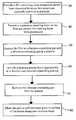
- FIG. 3shows a schematic illustration of the semiconductor device of FIG. 1, during the etching process of the current invention where an RIE plasma includes two halogen-containing gases.
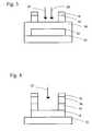
- FIG. 4shows a schematic illustration of the semiconductor device of FIG. 1, during the etching process of the current invention when one of the halogen-containing gases is removed from the plasma, thus leaving only one halogen-containing gas.
- FIG. 5shows a flowchart of an example of the method of the current invention.
- the present inventionaddresses the problem of removing portions of a thin film layer, while leaving the underlying layers intact. This problem can be solved by selective gas-phase removal of the exposed portion of a relatively inert thin film while preserving an underlying thin film. “Exposed portion” is defined as the part of the thin film layer which is not covered by either another device layer, a masking layer, or both. Instead, they are unprotected and in direct contact with the plasma in the etching process.
- the methodmay be used to integrate devices or to create complex or varying architecture within a device.
- TFRthin film resonator
- Reactive ion etchinghas the potential for high resolution patterning of piezoelectrics, or any material adjacent to an electrode, including nitrogen-containing layers and oxygen-containing layers.
- RIEis one of a number of industry-standard pattern transfer tools.
- a mask of etch-resistant materialis first formed on the substrate.
- the masked substrateis then placed in a high-vacuum chamber between parallel-plate electrodes.
- a reactive gasis next introduced into the chamber and an electric potential is applied between the electrodes. This potential is of sufficient magnitude to ionize the reactive gas, producing electrically charged radicals which are both chemically reactive and subject to acceleration induced by the applied electric field.
- Choice of the reactive gasdepends on the properties of the layer to be etched, the desired etching profile, the etching selectivity with respect to another layer in the structure, and compatibility with other gases in the process.
- the electrically charged gaseous environment mentioned aboveis generically known as a “plasma”.
- the positively charged ionsare accelerated toward the negatively charged cathode upon which the substrate rests.
- the ionsreact with unmasked substrate material to form a volatile product which is pumped away by the vacuum system.
- any conducting electrodes lying beneath the piezoelectric materialneed to be undamaged by the etching process of the piezoelectric material.
- the general processconsists of using a gas mixture which aggressively reacts with the subject (inert) film as well as an adjacent electrode. At some point during the etching process at least one component of this gas mixture is removed or changed, resulting in a less-aggressive etchant which, upon complete removal of the target film, leaves the adjacent electrode intact.
- a substrate ( 10 )is covered by a film consisting of a base electrode layer ( 12 ), a material layer ( 14 ), and an upper electrode layer ( 16 ).
- the material layer ( 14 )is preferably composed of a piezoelectric material such as zinc oxide or aluminum nitride, an oxygen-containing material, or a nitrogen-containing material.
- the electrode layers ( 12 ) and ( 16 )are preferably metallic.
- the material layer ( 14 )conforms to the underlying topology of base electrode layer ( 12 ) and is not necessarily planar as schematically shown in FIGS. 1-4.
- Both of the electrode layers ( 12 ) and ( 16 )preferably have a sheet resistance less or equal to 100 ohms/square. Either or both of the electrode layers ( 12 ) and ( 16 ) in the starting material may be patterned.
- FIGS. 2 through 4a schematic illustration of a semiconductor device during the fabrication process is shown. These figures are simplified schematic representations of the semiconductor device, and are not intended to limit the scope of the invention.
- a layerwhich is preferably continuous, is initially added to completely coat the upper electrode layer ( 16 ) and the exposed areas of the material layer ( 14 ).
- the layeris patterned by applying photoresist in the same pattern as that of the upper electrode layer ( 16 ), and then etching away the layer except where it overlies the upper electrode layer ( 16 ), forming the masking layer ( 18 ).
- the masking layer ( 18 )now patterned, provides the etch-resistant mask which allows a pattern to be etched onto the material layer ( 14 ).
- additional gasesmay be a part of the plasma to improve the etch rate.
- the two halogen-containing gases ( 20 ) and ( 22 )are chosen so that, in conduction, they effectively etch the exposed portion of the material layer ( 14 ).
- the exposed portion of the material layer ( 14 )is aggressively etched in the plasma containing the two halogen-containing gases ( 20 ) and ( 22 ). Efficient removal of the material layer ( 14 ) may be monitored by in-situ or ex-situ techniques including laser interferometery and RGA (residual gas analysis).
- one of the halogen-containing gases ( 22 )is removed from the plasma. After removing this halogen-containing gas ( 22 ), the diluted plasma continues to etch the material layer ( 14 ). Referring to FIG. 4, the exposed portion(s) of the material layer ( 14 ) is etched to completion, leaving a defined pattern. However, the plasma has a substantially negligible effect on removal of the base electrode layer ( 12 ), and the etch stops when the plasma reaches the base electrode layer ( 12 ). Although all of the exposed portion(s) of the material layer ( 14 ) is removed in FIG. 4, etching only desired portions of the material layer ( 14 ) is also an object of the invention.
- the present inventionprovides an etch process which solves the problem of selectively etching a piezoelectric layer such as an aluminum nitride layer while keeping an aluminum electrode underlayer intact.
- This embodimentinvolves the patterning of an aluminum nitride layer in a plasma containing both chlorine-containing gases and a fluorine-containing gas.
- a substrate ( 10 )is covered by a film consisting of a base aluminum electrode layer ( 12 ), an aluminum nitride layer ( 14 ), and an upper aluminum electrode layer ( 16 ).
- the aluminum nitride layer ( 14 )conforms to the underlying topology of base aluminum electrode layer ( 12 ) and is not necessarily planar as schematically shown in FIGS. 1-4.
- the substrate ( 10 )is broadly defined as a surface upon which the two aluminum electrode layers ( 12 ) and ( 16 ) and the aluminum nitride layer ( 14 ) are deposited.
- Silicon wafersare a preferred substrate ( 10 ) for use in this example of the method.
- the silicon substrate ( 10 )is not integral to device operation; it predominantly provides mechanical support.
- the silicon wafersare roughly 0.6 mm thick and about 200 mm in diameter. Perhaps thousands of devices are built on a single wafer.
- a 100 nanometer film of metal, for example aluminum,is deposited on the wafer surface. The deposition is carried out in a vacuum chamber via a physical vapor deposition or analogous process. A continuous conducting layer results.
- a lithographic processin which a thin layer of a photosensitive material is applied to completely coat the aluminum film is employed to pattern the aluminum layer. Exposure through a mask and immersion in a developer removes any photoresist exposed to light. Subsequent immersion in an aluminum etchant removes the uncovered aluminum but leaves behind the material protected by the remaining photoresist. When the remaining photoresist is removed in a solvent, an island of aluminum forms the base aluminum electrode layer ( 12 ) of the device. Although a patterned base aluminum electrode layer ( 12 ) is shown in FIGS. 1-4, it is not necessary to pattern the base aluminum electrode layer ( 12 ) or to pattern this aluminum electrode layer ( 12 ) with the above method in order to practice the method of the present invention. The decision to pattern the base aluminum electrode layer ( 12 ) depends on the type of device being fabricated.
- the sampleis returned to a vacuum chamber for the deposition of aluminum nitride, a piezoelectric material used in resonators.
- the aluminum nitride layer ( 14 )is deposited everywhere over the substrate, but the aluminum nitride layer ( 14 ) is left unpatterned, and is subsequently preferably coated with another film of aluminum metal. This second metal film is patterned and etched with the lithographic process described above, creating an upper aluminum electrode layer ( 16 ).
- the aluminum nitride layer ( 14 )is continuous (unpatterned). Because the aluminum nitride layer ( 14 ) completely covers aluminum layer ( 12 ), there is no direct electrical connection between the two aluminum electrode layers ( 12 ) and ( 16 ).
- the film essentially as described aboveis provided in step ( 30 ) of the present method, as detailed in the flowchart of FIG. 5 .
- a continuous layerpreferably composed of SiO X is initially added to completely coat the upper aluminum electrode layer ( 16 ) and the exposed areas of the aluminum nitride layer ( 14 ).
- the continuous layeris patterned in step ( 40 ) by applying photoresist in the same pattern as that of the upper aluminum electrode layer ( 16 ), and then etching away the continuous layer except where it overlies the upper electrode layer ( 16 ), forming the masking layer ( 18 ) shown in FIG. 2 .
- the masking layer ( 18 )now patterned, provides the etch-resistant mask which allows a pattern to be etched onto the aluminum nitride layer ( 14 ).
- step ( 50 )the aluminum nitride layer ( 14 ) is exposed to a plasma containing at least one fluorine-containing gas ( 20 ) and at least one chlorine-containing gas ( 22 ).
- a plasmacontaining at least one fluorine-containing gas ( 20 ) and at least one chlorine-containing gas ( 22 ).
- CHF 3is the fluorine-containing gas ( 20 )
- a combination of Cl 2 and BCl 3comprise the chlorine-containing gas ( 22 ).
- Aris preferably included in the plasma.
- the preferable flow rates for Cl 2 , BCl 3 , CHF 3 and Arare 30, 40, 5, and 15 sccm, respectively. These flow rates correspond to relative percentages of 33%, 44%, 6%, and 17% for Cl 2 , BCl 3 , CHF 3 and Ar, respectively.
- the combination of the fluorine-containing gas ( 20 ) and the chlorine-containing gas ( 22 ) in the plasmais quite aggressive in its attack on both the aluminum nitride layer ( 14 ) and the base aluminum electrode layer ( 12 ) in these devices. Therefore, the aggressive nature of the fluorine-containing gas ( 20 ) and the chlorine-containing gas ( 22 ) together in the plasma is used to remove the aluminum nitride overlying the base aluminum electrode layer ( 12 ), except where it is overlaid by the upper electrode layer ( 16 ) and masking layer ( 18 ).
- the exposed portion of the aluminum nitride layer ( 14 )is aggressively etched by the plasma of the fluorine-containing gas ( 20 ) and the chlorine-containing gas ( 22 ) in step ( 60 ).
- the gas composition of Cl 2 , BCl 3 , CHF 3 and Araluminum nitride etches at about 100 nm per minute.
- the end of the aluminum nitride etchis determined by timing or interferometry.
- the chlorine-containing gas ( 22 )must be removed before the etch breaks through the aluminum nitride and attacks the underlying base aluminum electrode layer ( 12 ). Because the aluminum film, for example, is relatively thin and the Cl 2 is so aggressive, if the Cl 2 is able to penetrate to the base aluminum electrode layer ( 12 ), the etch would quickly destroy the base aluminum electrode layer ( 12 ), thus fatally compromising the electronic device.
- the chlorine-containing gas ( 22 )is removed from the plasma in step ( 70 ).
- Cl 2 , BCl 3 , CHF 3 and Armake up the initial plasma
- Cl 2 , BCl 3 , and Arare all removed from the plasma.
- Aris not involved in the chemistry which aggressively etches the aluminum, if it is left in the plasma, it physically erodes the base aluminum electrode layer ( 12 ).
- the chlorine-containing gas ( 22 )is turned off, and the aluminum nitride continues etching, albeit much more slowly, in the fluorine-containing gas ( 20 ).
- the fluorine compoundetches the aluminum nitride at about ⁇ fraction (1/10) ⁇ the rate of the chlorine and fluorine combination, as much of the aluminum nitride as possible is removed with the more aggressive chemistry.
- the exposed portion of the aluminum nitride layer ( 14 )is etched to completion, leaving a defined pattern.
- the plasmacontains only the fluorine-containing gas ( 20 ).
- this gasis CHF 3 .
- SF 6is preferably added during step ( 80 ) to increase the fluorine content of the plasma.
- O 2is preferably added to the plasma, thereby liberating more fluorine from both CHF 3 and SF 6 . Utilizing a combination of CHF 3 , SF 6 , and O 2 , these gases are preferably released into the plasma at flow rates of 40, 40, and 5 sccm, respectively.
- SF 6 and CHF 3are used in equal parts without the addition of O 2 .
- the fluorine-containing gas ( 20 )tends to have a very limited etch rate on an aluminum film.
- the inability of fluorine gases to effectively etch aluminumis attributed to the formation of an AlF X compound at the surface of the aluminum which does not etch in fluorine. Due to the inability of fluorine to effectively etch aluminum, the aluminum nitride-etching process self-terminates in step ( 80 ) at the aluminum electrode surface. The base aluminum electrode layer ( 12 ) is thus preserved while the aluminum nitride layer ( 14 ) is completely removed at the patterned site.
- the device shown in FIG. 4has a signal path well confined to the resonator regions of the device, as the medium that would support lateral wave motion between the two electrodes has been eliminated.
- Selective etching of aluminum nitrideremoves superfluous material that supports shear wave propagation. By masking the top electrodes and etching the exposed aluminum nitride, but stopping the etch at the surface of the lower aluminum electrode, the electrical connection between the two electrodes is maintained. This enables enhanced device performance.
- the methodis also applicable to patterning and etching the upper aluminum electrode layer ( 16 ) and the aluminum nitride layer ( 14 ) concurrently.
- a continuous upper aluminum electrode layer ( 16 )is masked by a specific pattern.
- a reactive ion etching processis performed which includes chlorine-containing gases, for example BCl 3 and Cl 2 , in the initial plasma.
- a fluorine containing gasfor example, CHF 3
- any other gases which aid in the etch processfor example Ar
- the description of the inventionis not intended to limit the scope of the claims.
- the device which has been describedis preferably a thin film resonator with two resonators, the invention is also applicable in a situation where one, or more than two resonators are a part of the device.
- various architecturesare covered by the scope of the invention.
Landscapes
- Engineering & Computer Science (AREA)
- Manufacturing & Machinery (AREA)
- Drying Of Semiconductors (AREA)
Abstract
Description
Claims (29)
Priority Applications (1)
| Application Number | Priority Date | Filing Date | Title |
|---|---|---|---|
| US09/497,982US6306313B1 (en) | 2000-02-04 | 2000-02-04 | Selective etching of thin films |
Applications Claiming Priority (1)
| Application Number | Priority Date | Filing Date | Title |
|---|---|---|---|
| US09/497,982US6306313B1 (en) | 2000-02-04 | 2000-02-04 | Selective etching of thin films |
Publications (1)
| Publication Number | Publication Date |
|---|---|
| US6306313B1true US6306313B1 (en) | 2001-10-23 |
Family
ID=23979127
Family Applications (1)
| Application Number | Title | Priority Date | Filing Date |
|---|---|---|---|
| US09/497,982Expired - LifetimeUS6306313B1 (en) | 2000-02-04 | 2000-02-04 | Selective etching of thin films |
Country Status (1)
| Country | Link |
|---|---|
| US (1) | US6306313B1 (en) |
Cited By (10)
| Publication number | Priority date | Publication date | Assignee | Title |
|---|---|---|---|---|
| US6518860B2 (en)* | 2001-01-05 | 2003-02-11 | Nokia Mobile Phones Ltd | BAW filters having different center frequencies on a single substrate and a method for providing same |
| US6524971B1 (en)* | 1999-12-17 | 2003-02-25 | Agere Systems, Inc. | Method of deposition of films |
| US6617249B2 (en)* | 2001-03-05 | 2003-09-09 | Agilent Technologies, Inc. | Method for making thin film bulk acoustic resonators (FBARS) with different frequencies on a single substrate and apparatus embodying the method |
| US6874211B2 (en)* | 2001-03-05 | 2005-04-05 | Agilent Technologies, Inc. | Method for producing thin film bulk acoustic resonators (FBARs) with different frequencies on the same substrate by subtracting method and apparatus embodying the method |
| US20050140467A1 (en)* | 2002-08-06 | 2005-06-30 | Amy Duwel | Resonator system with a plurality of individual mechanically coupled resonators and method of making same |
| US20060008584A1 (en)* | 2003-11-26 | 2006-01-12 | Young-Jun Park | Method of forming carbon nanotube |
| US20080268575A1 (en)* | 2007-04-24 | 2008-10-30 | Maxim Integrated Products, Inc. | Orientation-dependent etching of deposited AIN for structural use and sacrificial layers in MEMS |
| WO2009142960A1 (en)* | 2008-05-22 | 2009-11-26 | Fujifilm Corporation | Etching piezoelectric material |
| US20130084441A1 (en)* | 2011-09-29 | 2013-04-04 | Seagate Technology Llc | Optical articles and methods of making same |
| EP2383775B1 (en)* | 2010-04-30 | 2017-03-15 | Commissariat à l'Énergie Atomique et aux Énergies Alternatives | Verfahren zum Erhalten einer AlN-Schicht mit deutlich vertikalen Flanken |
Citations (65)
| Publication number | Priority date | Publication date | Assignee | Title |
|---|---|---|---|---|
| US2303457A (en) | 1940-10-19 | 1942-12-01 | Westinghouse Electric & Mfg Co | Series speed-control units |
| US4502932A (en) | 1983-10-13 | 1985-03-05 | The United States Of America As Represented By The United States Department Of Energy | Acoustic resonator and method of making same |
| US4556812A (en) | 1983-10-13 | 1985-12-03 | The United States Of America As Represented By The United States Department Of Energy | Acoustic resonator with Al electrodes on an AlN layer and using a GaAs substrate |
| US4719383A (en) | 1985-05-20 | 1988-01-12 | The United States Of America As Represented By The United States Department Of Energy | Piezoelectric shear wave resonator and method of making same |
| US4890370A (en) | 1987-10-09 | 1990-01-02 | Murata Manufacturing Co., Ltd. | Manufacturing method for integrated resonator |
| US4988957A (en) | 1989-05-26 | 1991-01-29 | Iowa State University Research Foundation, Inc. | Electronically-tuned thin-film resonator/filter controlled oscillator |
| US5075641A (en) | 1990-12-04 | 1991-12-24 | Iowa State University Research Foundation, Inc. | High frequency oscillator comprising cointegrated thin film resonator and active device |
| US5166646A (en) | 1992-02-07 | 1992-11-24 | Motorola, Inc. | Integrated tunable resonators for use in oscillators and filters |
| US5185589A (en) | 1991-05-17 | 1993-02-09 | Westinghouse Electric Corp. | Microwave film bulk acoustic resonator and manifolded filter bank |
| US5231327A (en) | 1990-12-14 | 1993-07-27 | Tfr Technologies, Inc. | Optimized piezoelectric resonator-based networks |
| US5233259A (en) | 1991-02-19 | 1993-08-03 | Westinghouse Electric Corp. | Lateral field FBAR |
| US5232571A (en) | 1991-12-23 | 1993-08-03 | Iowa State University Research Foundation, Inc. | Aluminum nitride deposition using an AlN/Al sputter cycle technique |
| US5283458A (en) | 1992-03-30 | 1994-02-01 | Trw Inc. | Temperature stable semiconductor bulk acoustic resonator |
| US5291159A (en) | 1992-07-20 | 1994-03-01 | Westinghouse Electric Corp. | Acoustic resonator filter with electrically variable center frequency and bandwidth |
| US5294898A (en) | 1992-01-29 | 1994-03-15 | Motorola, Inc. | Wide bandwidth bandpass filter comprising parallel connected piezoelectric resonators |
| US5334960A (en) | 1993-02-16 | 1994-08-02 | Motorola, Inc. | Conjugately matched acoustic wave transducers and method |
| US5348617A (en) | 1991-12-23 | 1994-09-20 | Iowa State University Research Foundation, Inc. | Selective etching process |
| US5367308A (en) | 1992-05-29 | 1994-11-22 | Iowa State University Research Foundation, Inc. | Thin film resonating device |
| US5369053A (en) | 1989-10-24 | 1994-11-29 | Hewlett-Packard Company | Method for patterning aluminum metallizations |
| US5373268A (en) | 1993-02-01 | 1994-12-13 | Motorola, Inc. | Thin film resonator having stacked acoustic reflecting impedance matching layers and method |
| US5381385A (en) | 1993-08-04 | 1995-01-10 | Hewlett-Packard Company | Electrical interconnect for multilayer transducer elements of a two-dimensional transducer array |
| US5403701A (en) | 1991-12-13 | 1995-04-04 | Hewlett-Packard Company | Method of forming small geometry patterns on piezoelectric membrane films |
| US5438554A (en) | 1993-06-15 | 1995-08-01 | Hewlett-Packard Company | Tunable acoustic resonator for clinical ultrasonic transducers |
| US5446306A (en) | 1993-12-13 | 1995-08-29 | Trw Inc. | Thin film voltage-tuned semiconductor bulk acoustic resonator (SBAR) |
| US5552655A (en) | 1994-05-04 | 1996-09-03 | Trw Inc. | Low frequency mechanical resonator |
| US5587620A (en) | 1993-12-21 | 1996-12-24 | Hewlett-Packard Company | Tunable thin film acoustic resonators and method for making the same |
| US5596239A (en) | 1995-06-29 | 1997-01-21 | Motorola, Inc. | Enhanced quality factor resonator |
| US5597444A (en) | 1996-01-29 | 1997-01-28 | Micron Technology, Inc. | Method for etching semiconductor wafers |
| US5617065A (en) | 1995-06-29 | 1997-04-01 | Motorola, Inc. | Filter using enhanced quality factor resonator and method |
| US5630949A (en) | 1995-06-01 | 1997-05-20 | Tfr Technologies, Inc. | Method and apparatus for fabricating a piezoelectric resonator to a resonant frequency |
| US5646583A (en) | 1996-01-04 | 1997-07-08 | Rockwell International Corporation | Acoustic isolator having a high impedance layer of hafnium oxide |
| US5692279A (en) | 1995-08-17 | 1997-12-02 | Motorola | Method of making a monolithic thin film resonator lattice filter |
| US5698928A (en) | 1995-08-17 | 1997-12-16 | Motorola, Inc. | Thin film piezoelectric arrays with enhanced coupling and fabrication methods |
| US5702775A (en) | 1995-12-26 | 1997-12-30 | Motorola, Inc. | Microelectronic device package and method |
| US5707901A (en) | 1994-06-29 | 1998-01-13 | Motorola, Inc. | Method utilizing an etch stop layer |
| US5714917A (en) | 1996-10-02 | 1998-02-03 | Nokia Mobile Phones Limited | Device incorporating a tunable thin film bulk acoustic resonator for performing amplitude and phase modulation |
| US5741742A (en)* | 1993-09-10 | 1998-04-21 | Sony Corporation | Formation of aluminum-alloy pattern |
| US5760663A (en) | 1996-08-23 | 1998-06-02 | Motorola, Inc. | Elliptic baw resonator filter and method of making the same |
| US5780713A (en) | 1996-11-19 | 1998-07-14 | Hewlett-Packard Company | Post-fabrication tuning of acoustic resonators |
| US5789845A (en) | 1994-11-24 | 1998-08-04 | Mitsubishi Denki Kabushiki Kaisha | Film bulk acoustic wave device |
| US5801476A (en) | 1996-08-09 | 1998-09-01 | The United States Of America As Represented By The Secretary Of The Army | Thickness mode acoustic wave resonator |
| US5821833A (en) | 1995-12-26 | 1998-10-13 | Tfr Technologies, Inc. | Stacked crystal filter device and method of making |
| US5821170A (en) | 1996-09-30 | 1998-10-13 | Motorola, Inc. | Method for etching an insulating material |
| US5830774A (en) | 1996-06-24 | 1998-11-03 | Motorola, Inc. | Method for forming a metal pattern on a substrate |
| US5853601A (en) | 1997-04-03 | 1998-12-29 | Northrop Grumman Corporation | Top-via etch technique for forming dielectric membranes |
| US5858086A (en) | 1996-10-17 | 1999-01-12 | Hunter; Charles Eric | Growth of bulk single crystals of aluminum nitride |
| US5864261A (en) | 1994-05-23 | 1999-01-26 | Iowa State University Research Foundation | Multiple layer acoustical structures for thin-film resonator based circuits and systems |
| US5872493A (en) | 1997-03-13 | 1999-02-16 | Nokia Mobile Phones, Ltd. | Bulk acoustic wave (BAW) filter having a top portion that includes a protective acoustic mirror |
| US5873154A (en) | 1996-10-17 | 1999-02-23 | Nokia Mobile Phones Limited | Method for fabricating a resonator having an acoustic mirror |
| US5883575A (en) | 1997-08-12 | 1999-03-16 | Hewlett-Packard Company | RF-tags utilizing thin film bulk wave acoustic resonators |
| US5894647A (en) | 1997-06-30 | 1999-04-20 | Tfr Technologies, Inc. | Method for fabricating piezoelectric resonators and product |
| US5900163A (en) | 1996-05-08 | 1999-05-04 | Samsung Electronics Co., Ltd. | Methods for performing plasma etching operations on microelectronic structures |
| US5906950A (en) | 1996-01-22 | 1999-05-25 | Micron Technology, Inc. | Selective etch process |
| US5910756A (en) | 1997-05-21 | 1999-06-08 | Nokia Mobile Phones Limited | Filters and duplexers utilizing thin film stacked crystal filter structures and thin film bulk acoustic wave resonators |
| US5942958A (en) | 1998-07-27 | 1999-08-24 | Tfr Technologies, Inc. | Symmetrical piezoelectric resonator filter |
| US5963856A (en) | 1997-01-03 | 1999-10-05 | Lucent Technologies Inc | Wireless receiver including tunable RF bandpass filter |
| US6051907A (en) | 1996-10-10 | 2000-04-18 | Nokia Mobile Phones Limited | Method for performing on-wafer tuning of thin film bulk acoustic wave resonators (FBARS) |
| US6060818A (en) | 1998-06-02 | 2000-05-09 | Hewlett-Packard Company | SBAR structures and method of fabrication of SBAR.FBAR film processing techniques for the manufacturing of SBAR/BAR filters |
| US6081171A (en) | 1998-04-08 | 2000-06-27 | Nokia Mobile Phones Limited | Monolithic filters utilizing thin film bulk acoustic wave devices and minimum passive components for controlling the shape and width of a passband response |
| US6087198A (en) | 1998-02-12 | 2000-07-11 | Texas Instruments Incorporated | Low cost packaging for thin-film resonators and thin-film resonator-based filters |
| US6127768A (en) | 1997-05-09 | 2000-10-03 | Kobe Steel Usa, Inc. | Surface acoustic wave and bulk acoustic wave devices using a Zn.sub.(1-X) Yx O piezoelectric layer device |
| US6150703A (en) | 1998-06-29 | 2000-11-21 | Trw Inc. | Lateral mode suppression in semiconductor bulk acoustic resonator (SBAR) devices using tapered electrodes, and electrodes edge damping materials |
| US6198208B1 (en) | 1999-05-20 | 2001-03-06 | Tdk Corporation | Thin film piezoelectric device |
| US6204737B1 (en) | 1998-06-02 | 2001-03-20 | Nokia Mobile Phones, Ltd | Piezoelectric resonator structures with a bending element performing a voltage controlled switching function |
| US6215375B1 (en) | 1999-03-30 | 2001-04-10 | Agilent Technologies, Inc. | Bulk acoustic wave resonator with improved lateral mode suppression |
- 2000
- 2000-02-04USUS09/497,982patent/US6306313B1/ennot_activeExpired - Lifetime
Patent Citations (69)
| Publication number | Priority date | Publication date | Assignee | Title |
|---|---|---|---|---|
| US2303457A (en) | 1940-10-19 | 1942-12-01 | Westinghouse Electric & Mfg Co | Series speed-control units |
| US4502932A (en) | 1983-10-13 | 1985-03-05 | The United States Of America As Represented By The United States Department Of Energy | Acoustic resonator and method of making same |
| US4556812A (en) | 1983-10-13 | 1985-12-03 | The United States Of America As Represented By The United States Department Of Energy | Acoustic resonator with Al electrodes on an AlN layer and using a GaAs substrate |
| US4719383A (en) | 1985-05-20 | 1988-01-12 | The United States Of America As Represented By The United States Department Of Energy | Piezoelectric shear wave resonator and method of making same |
| US4890370A (en) | 1987-10-09 | 1990-01-02 | Murata Manufacturing Co., Ltd. | Manufacturing method for integrated resonator |
| US4988957A (en) | 1989-05-26 | 1991-01-29 | Iowa State University Research Foundation, Inc. | Electronically-tuned thin-film resonator/filter controlled oscillator |
| US5369053A (en) | 1989-10-24 | 1994-11-29 | Hewlett-Packard Company | Method for patterning aluminum metallizations |
| US5075641A (en) | 1990-12-04 | 1991-12-24 | Iowa State University Research Foundation, Inc. | High frequency oscillator comprising cointegrated thin film resonator and active device |
| US5231327A (en) | 1990-12-14 | 1993-07-27 | Tfr Technologies, Inc. | Optimized piezoelectric resonator-based networks |
| US5404628A (en) | 1990-12-14 | 1995-04-11 | Tfr Technologies, Inc. | Method for optimizing piezoelectric resonator-based networks |
| US5233259A (en) | 1991-02-19 | 1993-08-03 | Westinghouse Electric Corp. | Lateral field FBAR |
| US5185589A (en) | 1991-05-17 | 1993-02-09 | Westinghouse Electric Corp. | Microwave film bulk acoustic resonator and manifolded filter bank |
| US5403701A (en) | 1991-12-13 | 1995-04-04 | Hewlett-Packard Company | Method of forming small geometry patterns on piezoelectric membrane films |
| US5348617A (en) | 1991-12-23 | 1994-09-20 | Iowa State University Research Foundation, Inc. | Selective etching process |
| US5232571A (en) | 1991-12-23 | 1993-08-03 | Iowa State University Research Foundation, Inc. | Aluminum nitride deposition using an AlN/Al sputter cycle technique |
| US5294898A (en) | 1992-01-29 | 1994-03-15 | Motorola, Inc. | Wide bandwidth bandpass filter comprising parallel connected piezoelectric resonators |
| US5166646A (en) | 1992-02-07 | 1992-11-24 | Motorola, Inc. | Integrated tunable resonators for use in oscillators and filters |
| US5283458A (en) | 1992-03-30 | 1994-02-01 | Trw Inc. | Temperature stable semiconductor bulk acoustic resonator |
| US5367308A (en) | 1992-05-29 | 1994-11-22 | Iowa State University Research Foundation, Inc. | Thin film resonating device |
| US5291159A (en) | 1992-07-20 | 1994-03-01 | Westinghouse Electric Corp. | Acoustic resonator filter with electrically variable center frequency and bandwidth |
| US5373268A (en) | 1993-02-01 | 1994-12-13 | Motorola, Inc. | Thin film resonator having stacked acoustic reflecting impedance matching layers and method |
| US5334960A (en) | 1993-02-16 | 1994-08-02 | Motorola, Inc. | Conjugately matched acoustic wave transducers and method |
| US5438554A (en) | 1993-06-15 | 1995-08-01 | Hewlett-Packard Company | Tunable acoustic resonator for clinical ultrasonic transducers |
| US5381385A (en) | 1993-08-04 | 1995-01-10 | Hewlett-Packard Company | Electrical interconnect for multilayer transducer elements of a two-dimensional transducer array |
| US5741742A (en)* | 1993-09-10 | 1998-04-21 | Sony Corporation | Formation of aluminum-alloy pattern |
| US5446306A (en) | 1993-12-13 | 1995-08-29 | Trw Inc. | Thin film voltage-tuned semiconductor bulk acoustic resonator (SBAR) |
| US5587620A (en) | 1993-12-21 | 1996-12-24 | Hewlett-Packard Company | Tunable thin film acoustic resonators and method for making the same |
| US5873153A (en) | 1993-12-21 | 1999-02-23 | Hewlett-Packard Company | Method of making tunable thin film acoustic resonators |
| US5552655A (en) | 1994-05-04 | 1996-09-03 | Trw Inc. | Low frequency mechanical resonator |
| US5864261A (en) | 1994-05-23 | 1999-01-26 | Iowa State University Research Foundation | Multiple layer acoustical structures for thin-film resonator based circuits and systems |
| US5707901A (en) | 1994-06-29 | 1998-01-13 | Motorola, Inc. | Method utilizing an etch stop layer |
| US5789845A (en) | 1994-11-24 | 1998-08-04 | Mitsubishi Denki Kabushiki Kaisha | Film bulk acoustic wave device |
| US5630949A (en) | 1995-06-01 | 1997-05-20 | Tfr Technologies, Inc. | Method and apparatus for fabricating a piezoelectric resonator to a resonant frequency |
| US5884378A (en) | 1995-06-29 | 1999-03-23 | Motorola, Inc. | Method of making an enhanced quality factor resonator |
| US5617065A (en) | 1995-06-29 | 1997-04-01 | Motorola, Inc. | Filter using enhanced quality factor resonator and method |
| US5596239A (en) | 1995-06-29 | 1997-01-21 | Motorola, Inc. | Enhanced quality factor resonator |
| US5698928A (en) | 1995-08-17 | 1997-12-16 | Motorola, Inc. | Thin film piezoelectric arrays with enhanced coupling and fabrication methods |
| US5692279A (en) | 1995-08-17 | 1997-12-02 | Motorola | Method of making a monolithic thin film resonator lattice filter |
| US5928598A (en) | 1995-12-26 | 1999-07-27 | Motorola, Inc. | Method of making a microelectronic device package |
| US5702775A (en) | 1995-12-26 | 1997-12-30 | Motorola, Inc. | Microelectronic device package and method |
| US5821833A (en) | 1995-12-26 | 1998-10-13 | Tfr Technologies, Inc. | Stacked crystal filter device and method of making |
| US5646583A (en) | 1996-01-04 | 1997-07-08 | Rockwell International Corporation | Acoustic isolator having a high impedance layer of hafnium oxide |
| US5906950A (en) | 1996-01-22 | 1999-05-25 | Micron Technology, Inc. | Selective etch process |
| US5597444A (en) | 1996-01-29 | 1997-01-28 | Micron Technology, Inc. | Method for etching semiconductor wafers |
| US5900163A (en) | 1996-05-08 | 1999-05-04 | Samsung Electronics Co., Ltd. | Methods for performing plasma etching operations on microelectronic structures |
| US5830774A (en) | 1996-06-24 | 1998-11-03 | Motorola, Inc. | Method for forming a metal pattern on a substrate |
| US5801476A (en) | 1996-08-09 | 1998-09-01 | The United States Of America As Represented By The Secretary Of The Army | Thickness mode acoustic wave resonator |
| US5760663A (en) | 1996-08-23 | 1998-06-02 | Motorola, Inc. | Elliptic baw resonator filter and method of making the same |
| US5821170A (en) | 1996-09-30 | 1998-10-13 | Motorola, Inc. | Method for etching an insulating material |
| US5714917A (en) | 1996-10-02 | 1998-02-03 | Nokia Mobile Phones Limited | Device incorporating a tunable thin film bulk acoustic resonator for performing amplitude and phase modulation |
| US6051907A (en) | 1996-10-10 | 2000-04-18 | Nokia Mobile Phones Limited | Method for performing on-wafer tuning of thin film bulk acoustic wave resonators (FBARS) |
| US5873154A (en) | 1996-10-17 | 1999-02-23 | Nokia Mobile Phones Limited | Method for fabricating a resonator having an acoustic mirror |
| US5858086A (en) | 1996-10-17 | 1999-01-12 | Hunter; Charles Eric | Growth of bulk single crystals of aluminum nitride |
| US5780713A (en) | 1996-11-19 | 1998-07-14 | Hewlett-Packard Company | Post-fabrication tuning of acoustic resonators |
| US5963856A (en) | 1997-01-03 | 1999-10-05 | Lucent Technologies Inc | Wireless receiver including tunable RF bandpass filter |
| US5872493A (en) | 1997-03-13 | 1999-02-16 | Nokia Mobile Phones, Ltd. | Bulk acoustic wave (BAW) filter having a top portion that includes a protective acoustic mirror |
| US5853601A (en) | 1997-04-03 | 1998-12-29 | Northrop Grumman Corporation | Top-via etch technique for forming dielectric membranes |
| US6127768A (en) | 1997-05-09 | 2000-10-03 | Kobe Steel Usa, Inc. | Surface acoustic wave and bulk acoustic wave devices using a Zn.sub.(1-X) Yx O piezoelectric layer device |
| US5910756A (en) | 1997-05-21 | 1999-06-08 | Nokia Mobile Phones Limited | Filters and duplexers utilizing thin film stacked crystal filter structures and thin film bulk acoustic wave resonators |
| US5894647A (en) | 1997-06-30 | 1999-04-20 | Tfr Technologies, Inc. | Method for fabricating piezoelectric resonators and product |
| US5883575A (en) | 1997-08-12 | 1999-03-16 | Hewlett-Packard Company | RF-tags utilizing thin film bulk wave acoustic resonators |
| US6087198A (en) | 1998-02-12 | 2000-07-11 | Texas Instruments Incorporated | Low cost packaging for thin-film resonators and thin-film resonator-based filters |
| US6081171A (en) | 1998-04-08 | 2000-06-27 | Nokia Mobile Phones Limited | Monolithic filters utilizing thin film bulk acoustic wave devices and minimum passive components for controlling the shape and width of a passband response |
| US6060818A (en) | 1998-06-02 | 2000-05-09 | Hewlett-Packard Company | SBAR structures and method of fabrication of SBAR.FBAR film processing techniques for the manufacturing of SBAR/BAR filters |
| US6204737B1 (en) | 1998-06-02 | 2001-03-20 | Nokia Mobile Phones, Ltd | Piezoelectric resonator structures with a bending element performing a voltage controlled switching function |
| US6150703A (en) | 1998-06-29 | 2000-11-21 | Trw Inc. | Lateral mode suppression in semiconductor bulk acoustic resonator (SBAR) devices using tapered electrodes, and electrodes edge damping materials |
| US5942958A (en) | 1998-07-27 | 1999-08-24 | Tfr Technologies, Inc. | Symmetrical piezoelectric resonator filter |
| US6215375B1 (en) | 1999-03-30 | 2001-04-10 | Agilent Technologies, Inc. | Bulk acoustic wave resonator with improved lateral mode suppression |
| US6198208B1 (en) | 1999-05-20 | 2001-03-06 | Tdk Corporation | Thin film piezoelectric device |
Non-Patent Citations (3)
| Title |
|---|
| Rossnagel, S.M., Sputter deposition for semiconductor manufacturing, 1999, IBM J. Res. Develop, vol. 43, pp. 163-179. |
| Sparks, Douglas R, Plasma Etching of Si, SiO2, Si3N4, and Resist with Fluorine, Chlorine, and Bromine Compounds, 1992, J. Electrochem. Soc. vol. 139, pp. 1736-1741. |
| Suto, S., et al.; Highly Selective Etching of Si3N4 to SiO2 Employing Fluorine and Chlorine Atoms Generated by Microwave Discharge; 1989, J. Electrochem. Soc. vol. 136, pp. 2032-2034. |
Cited By (15)
| Publication number | Priority date | Publication date | Assignee | Title |
|---|---|---|---|---|
| US6524971B1 (en)* | 1999-12-17 | 2003-02-25 | Agere Systems, Inc. | Method of deposition of films |
| US6518860B2 (en)* | 2001-01-05 | 2003-02-11 | Nokia Mobile Phones Ltd | BAW filters having different center frequencies on a single substrate and a method for providing same |
| US6617249B2 (en)* | 2001-03-05 | 2003-09-09 | Agilent Technologies, Inc. | Method for making thin film bulk acoustic resonators (FBARS) with different frequencies on a single substrate and apparatus embodying the method |
| US6874211B2 (en)* | 2001-03-05 | 2005-04-05 | Agilent Technologies, Inc. | Method for producing thin film bulk acoustic resonators (FBARs) with different frequencies on the same substrate by subtracting method and apparatus embodying the method |
| US7312674B2 (en) | 2002-08-06 | 2007-12-25 | The Charles Stark Draper Laboratory, Inc. | Resonator system with a plurality of individual mechanically coupled resonators and method of making same |
| US20050140467A1 (en)* | 2002-08-06 | 2005-06-30 | Amy Duwel | Resonator system with a plurality of individual mechanically coupled resonators and method of making same |
| US20060008584A1 (en)* | 2003-11-26 | 2006-01-12 | Young-Jun Park | Method of forming carbon nanotube |
| US20080268575A1 (en)* | 2007-04-24 | 2008-10-30 | Maxim Integrated Products, Inc. | Orientation-dependent etching of deposited AIN for structural use and sacrificial layers in MEMS |
| US7960200B2 (en) | 2007-04-24 | 2011-06-14 | Maxim Integrated Products, Inc. | Orientation-dependent etching of deposited AlN for structural use and sacrificial layers in MEMS |
| WO2009142960A1 (en)* | 2008-05-22 | 2009-11-26 | Fujifilm Corporation | Etching piezoelectric material |
| US20110117311A1 (en)* | 2008-05-22 | 2011-05-19 | Jeffrey Birkmeyer | Etching piezoelectric material |
| US9085152B2 (en) | 2008-05-22 | 2015-07-21 | Fujifilm Corporation | Etching piezoelectric material |
| EP2383775B1 (en)* | 2010-04-30 | 2017-03-15 | Commissariat à l'Énergie Atomique et aux Énergies Alternatives | Verfahren zum Erhalten einer AlN-Schicht mit deutlich vertikalen Flanken |
| US20130084441A1 (en)* | 2011-09-29 | 2013-04-04 | Seagate Technology Llc | Optical articles and methods of making same |
| US9297959B2 (en)* | 2011-09-29 | 2016-03-29 | Seagate Technology Llc | Optical articles and methods of making same |
Similar Documents
| Publication | Publication Date | Title |
|---|---|---|
| US5160407A (en) | Low pressure anisotropic etch process for tantalum silicide or titanium silicide layer formed over polysilicon layer deposited on silicon oxide layer on semiconductor wafer | |
| US7662235B2 (en) | Method of cleaning etching apparatus | |
| US20030111439A1 (en) | Method of forming tapered electrodes for electronic devices | |
| JPS5812344B2 (en) | Method for forming metal patterns using copper as a base material | |
| EP1156132B1 (en) | Method of forming electrode film | |
| US4278492A (en) | Frequency trimming of surface acoustic wave devices | |
| JP2002344270A (en) | Manufacturing method of resonator | |
| JP2002359534A (en) | Manufacturing method of resonator | |
| JPS5812343B2 (en) | Plasma etching technology that prevents erosion of plasma-etched aluminum films after etching | |
| US6306313B1 (en) | Selective etching of thin films | |
| US6358429B1 (en) | Electronic device and method for producing the same | |
| US5347696A (en) | Method for manufacturing a multi-layer capacitor | |
| KR100745428B1 (en) | Method of isolation for acoustic resonator devices | |
| KR100252889B1 (en) | Platinum Etching Method | |
| CN112436815A (en) | Temperature compensation type surface acoustic wave device and manufacturing method thereof | |
| EP0995213B1 (en) | Gate electrode formation method | |
| US7435613B2 (en) | Methods of fabricating a membrane with improved mechanical integrity | |
| JPH06177086A (en) | Method and apparatus for dry etching | |
| US7247572B2 (en) | Method for fabricating a capacitor using a metal insulator metal structure | |
| JP3645658B2 (en) | Manufacturing method of semiconductor device | |
| US6743731B1 (en) | Method for making a radio frequency component and component produced thereby | |
| JP3409357B2 (en) | Etching method | |
| JPH07135198A (en) | Etching | |
| JPH04132221A (en) | Manufacture of semiconductor integrated circuit | |
| JP2002367971A (en) | Plasma processing apparatus, processing method using the same, and method for manufacturing semiconductor device |
Legal Events
| Date | Code | Title | Description |
|---|---|---|---|
| AS | Assignment | Owner name:LUCENT TECHNOLOGIES, INC., NEW JERSEY Free format text:ASSIGNMENT OF ASSIGNORS INTEREST;ASSIGNORS:FETTER, LINUS ALBERT;PASTALAN, JOHN Z.;REEL/FRAME:010802/0124 Effective date:20000204 | |
| STCF | Information on status: patent grant | Free format text:PATENTED CASE | |
| FPAY | Fee payment | Year of fee payment:4 | |
| FPAY | Fee payment | Year of fee payment:8 | |
| FPAY | Fee payment | Year of fee payment:12 | |
| AS | Assignment | Owner name:DEUTSCHE BANK AG NEW YORK BRANCH, AS COLLATERAL AG Free format text:PATENT SECURITY AGREEMENT;ASSIGNORS:LSI CORPORATION;AGERE SYSTEMS LLC;REEL/FRAME:032856/0031 Effective date:20140506 | |
| AS | Assignment | Owner name:AVAGO TECHNOLOGIES GENERAL IP (SINGAPORE) PTE. LTD Free format text:ASSIGNMENT OF ASSIGNORS INTEREST;ASSIGNOR:AGERE SYSTEMS LLC;REEL/FRAME:035365/0634 Effective date:20140804 | |
| AS | Assignment | Owner name:AGERE SYSTEMS LLC, PENNSYLVANIA Free format text:TERMINATION AND RELEASE OF SECURITY INTEREST IN PATENT RIGHTS (RELEASES RF 032856-0031);ASSIGNOR:DEUTSCHE BANK AG NEW YORK BRANCH, AS COLLATERAL AGENT;REEL/FRAME:037684/0039 Effective date:20160201 Owner name:LSI CORPORATION, CALIFORNIA Free format text:TERMINATION AND RELEASE OF SECURITY INTEREST IN PATENT RIGHTS (RELEASES RF 032856-0031);ASSIGNOR:DEUTSCHE BANK AG NEW YORK BRANCH, AS COLLATERAL AGENT;REEL/FRAME:037684/0039 Effective date:20160201 | |
| AS | Assignment | Owner name:BANK OF AMERICA, N.A., AS COLLATERAL AGENT, NORTH CAROLINA Free format text:PATENT SECURITY AGREEMENT;ASSIGNOR:AVAGO TECHNOLOGIES GENERAL IP (SINGAPORE) PTE. LTD.;REEL/FRAME:037808/0001 Effective date:20160201 Owner name:BANK OF AMERICA, N.A., AS COLLATERAL AGENT, NORTH Free format text:PATENT SECURITY AGREEMENT;ASSIGNOR:AVAGO TECHNOLOGIES GENERAL IP (SINGAPORE) PTE. LTD.;REEL/FRAME:037808/0001 Effective date:20160201 | |
| AS | Assignment | Owner name:AVAGO TECHNOLOGIES GENERAL IP (SINGAPORE) PTE. LTD., SINGAPORE Free format text:TERMINATION AND RELEASE OF SECURITY INTEREST IN PATENTS;ASSIGNOR:BANK OF AMERICA, N.A., AS COLLATERAL AGENT;REEL/FRAME:041710/0001 Effective date:20170119 Owner name:AVAGO TECHNOLOGIES GENERAL IP (SINGAPORE) PTE. LTD Free format text:TERMINATION AND RELEASE OF SECURITY INTEREST IN PATENTS;ASSIGNOR:BANK OF AMERICA, N.A., AS COLLATERAL AGENT;REEL/FRAME:041710/0001 Effective date:20170119 | |
| AS | Assignment | Owner name:AGERE SYSTEMS GUARDIAN CORP., PENNSYLVANIA Free format text:ASSIGNMENT OF ASSIGNORS INTEREST;ASSIGNOR:LUCENT TECHNOLOGIES INC.;REEL/FRAME:044484/0751 Effective date:20010130 | |
| AS | Assignment | Owner name:BELL SEMICONDUCTOR, LLC, ILLINOIS Free format text:ASSIGNMENT OF ASSIGNORS INTEREST;ASSIGNORS:AVAGO TECHNOLOGIES GENERAL IP (SINGAPORE) PTE. LTD.;BROADCOM CORPORATION;REEL/FRAME:044886/0001 Effective date:20171208 | |
| AS | Assignment | Owner name:CORTLAND CAPITAL MARKET SERVICES LLC, AS COLLATERA Free format text:SECURITY INTEREST;ASSIGNORS:HILCO PATENT ACQUISITION 56, LLC;BELL SEMICONDUCTOR, LLC;BELL NORTHERN RESEARCH, LLC;REEL/FRAME:045216/0020 Effective date:20180124 | |
| AS | Assignment | Owner name:BELL NORTHERN RESEARCH, LLC, ILLINOIS Free format text:SECURITY INTEREST;ASSIGNOR:CORTLAND CAPITAL MARKET SERVICES LLC;REEL/FRAME:060885/0001 Effective date:20220401 Owner name:BELL SEMICONDUCTOR, LLC, ILLINOIS Free format text:SECURITY INTEREST;ASSIGNOR:CORTLAND CAPITAL MARKET SERVICES LLC;REEL/FRAME:060885/0001 Effective date:20220401 Owner name:HILCO PATENT ACQUISITION 56, LLC, ILLINOIS Free format text:SECURITY INTEREST;ASSIGNOR:CORTLAND CAPITAL MARKET SERVICES LLC;REEL/FRAME:060885/0001 Effective date:20220401 |