US6306174B1 - Femoral component - Google Patents
Femoral componentDownload PDFInfo
- Publication number
- US6306174B1 US6306174B1US09/464,580US46458099AUS6306174B1US 6306174 B1US6306174 B1US 6306174B1US 46458099 AUS46458099 AUS 46458099AUS 6306174 B1US6306174 B1US 6306174B1
- Authority
- US
- United States
- Prior art keywords
- femoral component
- proximal
- stem
- set forth
- trunnion
- Prior art date
- Legal status (The legal status is an assumption and is not a legal conclusion. Google has not performed a legal analysis and makes no representation as to the accuracy of the status listed.)
- Expired - Lifetime
Links
- 239000004568cementSubstances0.000claimsabstractdescription13
- 230000008878couplingEffects0.000claimsabstractdescription10
- 238000010168coupling processMethods0.000claimsabstractdescription10
- 238000005859coupling reactionMethods0.000claimsabstractdescription10
- 210000004394hip jointAnatomy0.000claimsabstractdescription5
- 238000003780insertionMethods0.000claimsabstractdescription4
- 230000037431insertionEffects0.000claimsabstractdescription4
- 230000013011matingEffects0.000claimsdescription2
- 238000002513implantationMethods0.000claims1
- 210000000988bone and boneAnatomy0.000abstractdescription8
- 238000010276constructionMethods0.000description20
- 230000002093peripheral effectEffects0.000description3
- 239000002639bone cementSubstances0.000description2
- 238000001035dryingMethods0.000description1
- 230000000694effectsEffects0.000description1
- 239000012634fragmentSubstances0.000description1
- 210000001624hipAnatomy0.000description1
- 239000007943implantSubstances0.000description1
- 238000004519manufacturing processMethods0.000description1
- 239000000463materialSubstances0.000description1
- 238000000034methodMethods0.000description1
- 229920003023plasticPolymers0.000description1
- 239000004033plasticSubstances0.000description1
- 230000000284resting effectEffects0.000description1
Images


Classifications
- A—HUMAN NECESSITIES
- A61—MEDICAL OR VETERINARY SCIENCE; HYGIENE
- A61F—FILTERS IMPLANTABLE INTO BLOOD VESSELS; PROSTHESES; DEVICES PROVIDING PATENCY TO, OR PREVENTING COLLAPSING OF, TUBULAR STRUCTURES OF THE BODY, e.g. STENTS; ORTHOPAEDIC, NURSING OR CONTRACEPTIVE DEVICES; FOMENTATION; TREATMENT OR PROTECTION OF EYES OR EARS; BANDAGES, DRESSINGS OR ABSORBENT PADS; FIRST-AID KITS
- A61F2/00—Filters implantable into blood vessels; Prostheses, i.e. artificial substitutes or replacements for parts of the body; Appliances for connecting them with the body; Devices providing patency to, or preventing collapsing of, tubular structures of the body, e.g. stents
- A61F2/02—Prostheses implantable into the body
- A61F2/30—Joints
- A61F2/32—Joints for the hip
- A61F2/36—Femoral heads ; Femoral endoprostheses
- A61F2/3609—Femoral heads or necks; Connections of endoprosthetic heads or necks to endoprosthetic femoral shafts
- A—HUMAN NECESSITIES
- A61—MEDICAL OR VETERINARY SCIENCE; HYGIENE
- A61F—FILTERS IMPLANTABLE INTO BLOOD VESSELS; PROSTHESES; DEVICES PROVIDING PATENCY TO, OR PREVENTING COLLAPSING OF, TUBULAR STRUCTURES OF THE BODY, e.g. STENTS; ORTHOPAEDIC, NURSING OR CONTRACEPTIVE DEVICES; FOMENTATION; TREATMENT OR PROTECTION OF EYES OR EARS; BANDAGES, DRESSINGS OR ABSORBENT PADS; FIRST-AID KITS
- A61F2/00—Filters implantable into blood vessels; Prostheses, i.e. artificial substitutes or replacements for parts of the body; Appliances for connecting them with the body; Devices providing patency to, or preventing collapsing of, tubular structures of the body, e.g. stents
- A61F2/02—Prostheses implantable into the body
- A61F2/30—Joints
- A61F2/32—Joints for the hip
- A61F2/36—Femoral heads ; Femoral endoprostheses
- A61F2/3662—Femoral shafts
- A61F2/367—Proximal or metaphyseal parts of shafts
- A—HUMAN NECESSITIES
- A61—MEDICAL OR VETERINARY SCIENCE; HYGIENE
- A61F—FILTERS IMPLANTABLE INTO BLOOD VESSELS; PROSTHESES; DEVICES PROVIDING PATENCY TO, OR PREVENTING COLLAPSING OF, TUBULAR STRUCTURES OF THE BODY, e.g. STENTS; ORTHOPAEDIC, NURSING OR CONTRACEPTIVE DEVICES; FOMENTATION; TREATMENT OR PROTECTION OF EYES OR EARS; BANDAGES, DRESSINGS OR ABSORBENT PADS; FIRST-AID KITS
- A61F2/00—Filters implantable into blood vessels; Prostheses, i.e. artificial substitutes or replacements for parts of the body; Appliances for connecting them with the body; Devices providing patency to, or preventing collapsing of, tubular structures of the body, e.g. stents
- A61F2/02—Prostheses implantable into the body
- A61F2/30—Joints
- A61F2002/30001—Additional features of subject-matter classified in A61F2/28, A61F2/30 and subgroups thereof
- A61F2002/30316—The prosthesis having different structural features at different locations within the same prosthesis; Connections between prosthetic parts; Special structural features of bone or joint prostheses not otherwise provided for
- A61F2002/30329—Connections or couplings between prosthetic parts, e.g. between modular parts; Connecting elements
- A61F2002/30331—Connections or couplings between prosthetic parts, e.g. between modular parts; Connecting elements made by longitudinally pushing a protrusion into a complementarily-shaped recess, e.g. held by friction fit
- A61F2002/30332—Conically- or frustoconically-shaped protrusion and recess
- A61F2002/30339—Double cones, i.e. connecting element having two conical connections, one at each of its opposite ends
- A—HUMAN NECESSITIES
- A61—MEDICAL OR VETERINARY SCIENCE; HYGIENE
- A61F—FILTERS IMPLANTABLE INTO BLOOD VESSELS; PROSTHESES; DEVICES PROVIDING PATENCY TO, OR PREVENTING COLLAPSING OF, TUBULAR STRUCTURES OF THE BODY, e.g. STENTS; ORTHOPAEDIC, NURSING OR CONTRACEPTIVE DEVICES; FOMENTATION; TREATMENT OR PROTECTION OF EYES OR EARS; BANDAGES, DRESSINGS OR ABSORBENT PADS; FIRST-AID KITS
- A61F2/00—Filters implantable into blood vessels; Prostheses, i.e. artificial substitutes or replacements for parts of the body; Appliances for connecting them with the body; Devices providing patency to, or preventing collapsing of, tubular structures of the body, e.g. stents
- A61F2/02—Prostheses implantable into the body
- A61F2/30—Joints
- A61F2002/30001—Additional features of subject-matter classified in A61F2/28, A61F2/30 and subgroups thereof
- A61F2002/30316—The prosthesis having different structural features at different locations within the same prosthesis; Connections between prosthetic parts; Special structural features of bone or joint prostheses not otherwise provided for
- A61F2002/30329—Connections or couplings between prosthetic parts, e.g. between modular parts; Connecting elements
- A61F2002/30331—Connections or couplings between prosthetic parts, e.g. between modular parts; Connecting elements made by longitudinally pushing a protrusion into a complementarily-shaped recess, e.g. held by friction fit
- A61F2002/30354—Cylindrically-shaped protrusion and recess, e.g. cylinder of circular basis
- A—HUMAN NECESSITIES
- A61—MEDICAL OR VETERINARY SCIENCE; HYGIENE
- A61F—FILTERS IMPLANTABLE INTO BLOOD VESSELS; PROSTHESES; DEVICES PROVIDING PATENCY TO, OR PREVENTING COLLAPSING OF, TUBULAR STRUCTURES OF THE BODY, e.g. STENTS; ORTHOPAEDIC, NURSING OR CONTRACEPTIVE DEVICES; FOMENTATION; TREATMENT OR PROTECTION OF EYES OR EARS; BANDAGES, DRESSINGS OR ABSORBENT PADS; FIRST-AID KITS
- A61F2/00—Filters implantable into blood vessels; Prostheses, i.e. artificial substitutes or replacements for parts of the body; Appliances for connecting them with the body; Devices providing patency to, or preventing collapsing of, tubular structures of the body, e.g. stents
- A61F2/02—Prostheses implantable into the body
- A61F2/30—Joints
- A61F2002/30001—Additional features of subject-matter classified in A61F2/28, A61F2/30 and subgroups thereof
- A61F2002/30316—The prosthesis having different structural features at different locations within the same prosthesis; Connections between prosthetic parts; Special structural features of bone or joint prostheses not otherwise provided for
- A61F2002/30329—Connections or couplings between prosthetic parts, e.g. between modular parts; Connecting elements
- A61F2002/30405—Connections or couplings between prosthetic parts, e.g. between modular parts; Connecting elements made by screwing complementary threads machined on the parts themselves
- A—HUMAN NECESSITIES
- A61—MEDICAL OR VETERINARY SCIENCE; HYGIENE
- A61F—FILTERS IMPLANTABLE INTO BLOOD VESSELS; PROSTHESES; DEVICES PROVIDING PATENCY TO, OR PREVENTING COLLAPSING OF, TUBULAR STRUCTURES OF THE BODY, e.g. STENTS; ORTHOPAEDIC, NURSING OR CONTRACEPTIVE DEVICES; FOMENTATION; TREATMENT OR PROTECTION OF EYES OR EARS; BANDAGES, DRESSINGS OR ABSORBENT PADS; FIRST-AID KITS
- A61F2/00—Filters implantable into blood vessels; Prostheses, i.e. artificial substitutes or replacements for parts of the body; Appliances for connecting them with the body; Devices providing patency to, or preventing collapsing of, tubular structures of the body, e.g. stents
- A61F2/02—Prostheses implantable into the body
- A61F2/30—Joints
- A61F2002/30001—Additional features of subject-matter classified in A61F2/28, A61F2/30 and subgroups thereof
- A61F2002/30316—The prosthesis having different structural features at different locations within the same prosthesis; Connections between prosthetic parts; Special structural features of bone or joint prostheses not otherwise provided for
- A61F2002/30329—Connections or couplings between prosthetic parts, e.g. between modular parts; Connecting elements
- A61F2002/30433—Connections or couplings between prosthetic parts, e.g. between modular parts; Connecting elements using additional screws, bolts, dowels, rivets or washers e.g. connecting screws
- A—HUMAN NECESSITIES
- A61—MEDICAL OR VETERINARY SCIENCE; HYGIENE
- A61F—FILTERS IMPLANTABLE INTO BLOOD VESSELS; PROSTHESES; DEVICES PROVIDING PATENCY TO, OR PREVENTING COLLAPSING OF, TUBULAR STRUCTURES OF THE BODY, e.g. STENTS; ORTHOPAEDIC, NURSING OR CONTRACEPTIVE DEVICES; FOMENTATION; TREATMENT OR PROTECTION OF EYES OR EARS; BANDAGES, DRESSINGS OR ABSORBENT PADS; FIRST-AID KITS
- A61F2/00—Filters implantable into blood vessels; Prostheses, i.e. artificial substitutes or replacements for parts of the body; Appliances for connecting them with the body; Devices providing patency to, or preventing collapsing of, tubular structures of the body, e.g. stents
- A61F2/02—Prostheses implantable into the body
- A61F2/30—Joints
- A61F2002/30001—Additional features of subject-matter classified in A61F2/28, A61F2/30 and subgroups thereof
- A61F2002/30316—The prosthesis having different structural features at different locations within the same prosthesis; Connections between prosthetic parts; Special structural features of bone or joint prostheses not otherwise provided for
- A61F2002/30329—Connections or couplings between prosthetic parts, e.g. between modular parts; Connecting elements
- A61F2002/30476—Connections or couplings between prosthetic parts, e.g. between modular parts; Connecting elements locked by an additional locking mechanism
- A61F2002/30492—Connections or couplings between prosthetic parts, e.g. between modular parts; Connecting elements locked by an additional locking mechanism using a locking pin
- A—HUMAN NECESSITIES
- A61—MEDICAL OR VETERINARY SCIENCE; HYGIENE
- A61F—FILTERS IMPLANTABLE INTO BLOOD VESSELS; PROSTHESES; DEVICES PROVIDING PATENCY TO, OR PREVENTING COLLAPSING OF, TUBULAR STRUCTURES OF THE BODY, e.g. STENTS; ORTHOPAEDIC, NURSING OR CONTRACEPTIVE DEVICES; FOMENTATION; TREATMENT OR PROTECTION OF EYES OR EARS; BANDAGES, DRESSINGS OR ABSORBENT PADS; FIRST-AID KITS
- A61F2/00—Filters implantable into blood vessels; Prostheses, i.e. artificial substitutes or replacements for parts of the body; Appliances for connecting them with the body; Devices providing patency to, or preventing collapsing of, tubular structures of the body, e.g. stents
- A61F2/02—Prostheses implantable into the body
- A61F2/30—Joints
- A61F2002/30001—Additional features of subject-matter classified in A61F2/28, A61F2/30 and subgroups thereof
- A61F2002/30316—The prosthesis having different structural features at different locations within the same prosthesis; Connections between prosthetic parts; Special structural features of bone or joint prostheses not otherwise provided for
- A61F2002/30329—Connections or couplings between prosthetic parts, e.g. between modular parts; Connecting elements
- A61F2002/30476—Connections or couplings between prosthetic parts, e.g. between modular parts; Connecting elements locked by an additional locking mechanism
- A61F2002/30507—Connections or couplings between prosthetic parts, e.g. between modular parts; Connecting elements locked by an additional locking mechanism using a threaded locking member, e.g. a locking screw or a set screw
- A—HUMAN NECESSITIES
- A61—MEDICAL OR VETERINARY SCIENCE; HYGIENE
- A61F—FILTERS IMPLANTABLE INTO BLOOD VESSELS; PROSTHESES; DEVICES PROVIDING PATENCY TO, OR PREVENTING COLLAPSING OF, TUBULAR STRUCTURES OF THE BODY, e.g. STENTS; ORTHOPAEDIC, NURSING OR CONTRACEPTIVE DEVICES; FOMENTATION; TREATMENT OR PROTECTION OF EYES OR EARS; BANDAGES, DRESSINGS OR ABSORBENT PADS; FIRST-AID KITS
- A61F2/00—Filters implantable into blood vessels; Prostheses, i.e. artificial substitutes or replacements for parts of the body; Appliances for connecting them with the body; Devices providing patency to, or preventing collapsing of, tubular structures of the body, e.g. stents
- A61F2/02—Prostheses implantable into the body
- A61F2/30—Joints
- A61F2002/30001—Additional features of subject-matter classified in A61F2/28, A61F2/30 and subgroups thereof
- A61F2002/30316—The prosthesis having different structural features at different locations within the same prosthesis; Connections between prosthetic parts; Special structural features of bone or joint prostheses not otherwise provided for
- A61F2002/30329—Connections or couplings between prosthetic parts, e.g. between modular parts; Connecting elements
- A61F2002/30476—Connections or couplings between prosthetic parts, e.g. between modular parts; Connecting elements locked by an additional locking mechanism
- A61F2002/30517—Connections or couplings between prosthetic parts, e.g. between modular parts; Connecting elements locked by an additional locking mechanism using a locking plate
- A—HUMAN NECESSITIES
- A61—MEDICAL OR VETERINARY SCIENCE; HYGIENE
- A61F—FILTERS IMPLANTABLE INTO BLOOD VESSELS; PROSTHESES; DEVICES PROVIDING PATENCY TO, OR PREVENTING COLLAPSING OF, TUBULAR STRUCTURES OF THE BODY, e.g. STENTS; ORTHOPAEDIC, NURSING OR CONTRACEPTIVE DEVICES; FOMENTATION; TREATMENT OR PROTECTION OF EYES OR EARS; BANDAGES, DRESSINGS OR ABSORBENT PADS; FIRST-AID KITS
- A61F2/00—Filters implantable into blood vessels; Prostheses, i.e. artificial substitutes or replacements for parts of the body; Appliances for connecting them with the body; Devices providing patency to, or preventing collapsing of, tubular structures of the body, e.g. stents
- A61F2/02—Prostheses implantable into the body
- A61F2/30—Joints
- A61F2002/30001—Additional features of subject-matter classified in A61F2/28, A61F2/30 and subgroups thereof
- A61F2002/30316—The prosthesis having different structural features at different locations within the same prosthesis; Connections between prosthetic parts; Special structural features of bone or joint prostheses not otherwise provided for
- A61F2002/30535—Special structural features of bone or joint prostheses not otherwise provided for
- A61F2002/30537—Special structural features of bone or joint prostheses not otherwise provided for adjustable
- A61F2002/30538—Special structural features of bone or joint prostheses not otherwise provided for adjustable for adjusting angular orientation
- A61F2002/3054—Special structural features of bone or joint prostheses not otherwise provided for adjustable for adjusting angular orientation about a connection axis or implantation axis for selecting any one of a plurality of radial orientations between two modular parts, e.g. Morse taper connections, at discrete positions, angular positions or continuous positions
- A—HUMAN NECESSITIES
- A61—MEDICAL OR VETERINARY SCIENCE; HYGIENE
- A61F—FILTERS IMPLANTABLE INTO BLOOD VESSELS; PROSTHESES; DEVICES PROVIDING PATENCY TO, OR PREVENTING COLLAPSING OF, TUBULAR STRUCTURES OF THE BODY, e.g. STENTS; ORTHOPAEDIC, NURSING OR CONTRACEPTIVE DEVICES; FOMENTATION; TREATMENT OR PROTECTION OF EYES OR EARS; BANDAGES, DRESSINGS OR ABSORBENT PADS; FIRST-AID KITS
- A61F2/00—Filters implantable into blood vessels; Prostheses, i.e. artificial substitutes or replacements for parts of the body; Appliances for connecting them with the body; Devices providing patency to, or preventing collapsing of, tubular structures of the body, e.g. stents
- A61F2/02—Prostheses implantable into the body
- A61F2/30—Joints
- A61F2002/30001—Additional features of subject-matter classified in A61F2/28, A61F2/30 and subgroups thereof
- A61F2002/30316—The prosthesis having different structural features at different locations within the same prosthesis; Connections between prosthetic parts; Special structural features of bone or joint prostheses not otherwise provided for
- A61F2002/30535—Special structural features of bone or joint prostheses not otherwise provided for
- A61F2002/30594—Special structural features of bone or joint prostheses not otherwise provided for slotted, e.g. radial or meridian slot ending in a polar aperture, non-polar slots, horizontal or arcuate slots
- A—HUMAN NECESSITIES
- A61—MEDICAL OR VETERINARY SCIENCE; HYGIENE
- A61F—FILTERS IMPLANTABLE INTO BLOOD VESSELS; PROSTHESES; DEVICES PROVIDING PATENCY TO, OR PREVENTING COLLAPSING OF, TUBULAR STRUCTURES OF THE BODY, e.g. STENTS; ORTHOPAEDIC, NURSING OR CONTRACEPTIVE DEVICES; FOMENTATION; TREATMENT OR PROTECTION OF EYES OR EARS; BANDAGES, DRESSINGS OR ABSORBENT PADS; FIRST-AID KITS
- A61F2/00—Filters implantable into blood vessels; Prostheses, i.e. artificial substitutes or replacements for parts of the body; Appliances for connecting them with the body; Devices providing patency to, or preventing collapsing of, tubular structures of the body, e.g. stents
- A61F2/02—Prostheses implantable into the body
- A61F2/30—Joints
- A61F2002/30001—Additional features of subject-matter classified in A61F2/28, A61F2/30 and subgroups thereof
- A61F2002/30316—The prosthesis having different structural features at different locations within the same prosthesis; Connections between prosthetic parts; Special structural features of bone or joint prostheses not otherwise provided for
- A61F2002/30535—Special structural features of bone or joint prostheses not otherwise provided for
- A61F2002/30604—Special structural features of bone or joint prostheses not otherwise provided for modular
- A—HUMAN NECESSITIES
- A61—MEDICAL OR VETERINARY SCIENCE; HYGIENE
- A61F—FILTERS IMPLANTABLE INTO BLOOD VESSELS; PROSTHESES; DEVICES PROVIDING PATENCY TO, OR PREVENTING COLLAPSING OF, TUBULAR STRUCTURES OF THE BODY, e.g. STENTS; ORTHOPAEDIC, NURSING OR CONTRACEPTIVE DEVICES; FOMENTATION; TREATMENT OR PROTECTION OF EYES OR EARS; BANDAGES, DRESSINGS OR ABSORBENT PADS; FIRST-AID KITS
- A61F2/00—Filters implantable into blood vessels; Prostheses, i.e. artificial substitutes or replacements for parts of the body; Appliances for connecting them with the body; Devices providing patency to, or preventing collapsing of, tubular structures of the body, e.g. stents
- A61F2/02—Prostheses implantable into the body
- A61F2/30—Joints
- A61F2/30767—Special external or bone-contacting surface, e.g. coating for improving bone ingrowth
- A61F2/30771—Special external or bone-contacting surface, e.g. coating for improving bone ingrowth applied in original prostheses, e.g. holes or grooves
- A61F2002/30772—Apertures or holes, e.g. of circular cross section
- A61F2002/30774—Apertures or holes, e.g. of circular cross section internally-threaded
- A—HUMAN NECESSITIES
- A61—MEDICAL OR VETERINARY SCIENCE; HYGIENE
- A61F—FILTERS IMPLANTABLE INTO BLOOD VESSELS; PROSTHESES; DEVICES PROVIDING PATENCY TO, OR PREVENTING COLLAPSING OF, TUBULAR STRUCTURES OF THE BODY, e.g. STENTS; ORTHOPAEDIC, NURSING OR CONTRACEPTIVE DEVICES; FOMENTATION; TREATMENT OR PROTECTION OF EYES OR EARS; BANDAGES, DRESSINGS OR ABSORBENT PADS; FIRST-AID KITS
- A61F2/00—Filters implantable into blood vessels; Prostheses, i.e. artificial substitutes or replacements for parts of the body; Appliances for connecting them with the body; Devices providing patency to, or preventing collapsing of, tubular structures of the body, e.g. stents
- A61F2/02—Prostheses implantable into the body
- A61F2/30—Joints
- A61F2/30767—Special external or bone-contacting surface, e.g. coating for improving bone ingrowth
- A61F2/30771—Special external or bone-contacting surface, e.g. coating for improving bone ingrowth applied in original prostheses, e.g. holes or grooves
- A61F2002/30772—Apertures or holes, e.g. of circular cross section
- A61F2002/30784—Plurality of holes
- A61F2002/30785—Plurality of holes parallel
- A—HUMAN NECESSITIES
- A61—MEDICAL OR VETERINARY SCIENCE; HYGIENE
- A61F—FILTERS IMPLANTABLE INTO BLOOD VESSELS; PROSTHESES; DEVICES PROVIDING PATENCY TO, OR PREVENTING COLLAPSING OF, TUBULAR STRUCTURES OF THE BODY, e.g. STENTS; ORTHOPAEDIC, NURSING OR CONTRACEPTIVE DEVICES; FOMENTATION; TREATMENT OR PROTECTION OF EYES OR EARS; BANDAGES, DRESSINGS OR ABSORBENT PADS; FIRST-AID KITS
- A61F2/00—Filters implantable into blood vessels; Prostheses, i.e. artificial substitutes or replacements for parts of the body; Appliances for connecting them with the body; Devices providing patency to, or preventing collapsing of, tubular structures of the body, e.g. stents
- A61F2/02—Prostheses implantable into the body
- A61F2/30—Joints
- A61F2/30767—Special external or bone-contacting surface, e.g. coating for improving bone ingrowth
- A61F2/30771—Special external or bone-contacting surface, e.g. coating for improving bone ingrowth applied in original prostheses, e.g. holes or grooves
- A61F2002/30772—Apertures or holes, e.g. of circular cross section
- A61F2002/30784—Plurality of holes
- A61F2002/30787—Plurality of holes inclined obliquely with respect to each other
- A—HUMAN NECESSITIES
- A61—MEDICAL OR VETERINARY SCIENCE; HYGIENE
- A61F—FILTERS IMPLANTABLE INTO BLOOD VESSELS; PROSTHESES; DEVICES PROVIDING PATENCY TO, OR PREVENTING COLLAPSING OF, TUBULAR STRUCTURES OF THE BODY, e.g. STENTS; ORTHOPAEDIC, NURSING OR CONTRACEPTIVE DEVICES; FOMENTATION; TREATMENT OR PROTECTION OF EYES OR EARS; BANDAGES, DRESSINGS OR ABSORBENT PADS; FIRST-AID KITS
- A61F2/00—Filters implantable into blood vessels; Prostheses, i.e. artificial substitutes or replacements for parts of the body; Appliances for connecting them with the body; Devices providing patency to, or preventing collapsing of, tubular structures of the body, e.g. stents
- A61F2/02—Prostheses implantable into the body
- A61F2/30—Joints
- A61F2/30767—Special external or bone-contacting surface, e.g. coating for improving bone ingrowth
- A61F2/30771—Special external or bone-contacting surface, e.g. coating for improving bone ingrowth applied in original prostheses, e.g. holes or grooves
- A61F2002/30795—Blind bores, e.g. of circular cross-section
- A61F2002/30797—Blind bores, e.g. of circular cross-section internally-threaded
- A—HUMAN NECESSITIES
- A61—MEDICAL OR VETERINARY SCIENCE; HYGIENE
- A61F—FILTERS IMPLANTABLE INTO BLOOD VESSELS; PROSTHESES; DEVICES PROVIDING PATENCY TO, OR PREVENTING COLLAPSING OF, TUBULAR STRUCTURES OF THE BODY, e.g. STENTS; ORTHOPAEDIC, NURSING OR CONTRACEPTIVE DEVICES; FOMENTATION; TREATMENT OR PROTECTION OF EYES OR EARS; BANDAGES, DRESSINGS OR ABSORBENT PADS; FIRST-AID KITS
- A61F2/00—Filters implantable into blood vessels; Prostheses, i.e. artificial substitutes or replacements for parts of the body; Appliances for connecting them with the body; Devices providing patency to, or preventing collapsing of, tubular structures of the body, e.g. stents
- A61F2/02—Prostheses implantable into the body
- A61F2/30—Joints
- A61F2/30767—Special external or bone-contacting surface, e.g. coating for improving bone ingrowth
- A61F2/30771—Special external or bone-contacting surface, e.g. coating for improving bone ingrowth applied in original prostheses, e.g. holes or grooves
- A61F2002/30795—Blind bores, e.g. of circular cross-section
- A61F2002/30807—Plurality of blind bores
- A61F2002/30808—Plurality of blind bores parallel
- A—HUMAN NECESSITIES
- A61—MEDICAL OR VETERINARY SCIENCE; HYGIENE
- A61F—FILTERS IMPLANTABLE INTO BLOOD VESSELS; PROSTHESES; DEVICES PROVIDING PATENCY TO, OR PREVENTING COLLAPSING OF, TUBULAR STRUCTURES OF THE BODY, e.g. STENTS; ORTHOPAEDIC, NURSING OR CONTRACEPTIVE DEVICES; FOMENTATION; TREATMENT OR PROTECTION OF EYES OR EARS; BANDAGES, DRESSINGS OR ABSORBENT PADS; FIRST-AID KITS
- A61F2/00—Filters implantable into blood vessels; Prostheses, i.e. artificial substitutes or replacements for parts of the body; Appliances for connecting them with the body; Devices providing patency to, or preventing collapsing of, tubular structures of the body, e.g. stents
- A61F2/02—Prostheses implantable into the body
- A61F2/30—Joints
- A61F2/30767—Special external or bone-contacting surface, e.g. coating for improving bone ingrowth
- A61F2/30771—Special external or bone-contacting surface, e.g. coating for improving bone ingrowth applied in original prostheses, e.g. holes or grooves
- A61F2002/30795—Blind bores, e.g. of circular cross-section
- A61F2002/30807—Plurality of blind bores
- A61F2002/3081—Plurality of blind bores inclined obliquely with respect to each other
- A—HUMAN NECESSITIES
- A61—MEDICAL OR VETERINARY SCIENCE; HYGIENE
- A61F—FILTERS IMPLANTABLE INTO BLOOD VESSELS; PROSTHESES; DEVICES PROVIDING PATENCY TO, OR PREVENTING COLLAPSING OF, TUBULAR STRUCTURES OF THE BODY, e.g. STENTS; ORTHOPAEDIC, NURSING OR CONTRACEPTIVE DEVICES; FOMENTATION; TREATMENT OR PROTECTION OF EYES OR EARS; BANDAGES, DRESSINGS OR ABSORBENT PADS; FIRST-AID KITS
- A61F2/00—Filters implantable into blood vessels; Prostheses, i.e. artificial substitutes or replacements for parts of the body; Appliances for connecting them with the body; Devices providing patency to, or preventing collapsing of, tubular structures of the body, e.g. stents
- A61F2/02—Prostheses implantable into the body
- A61F2/30—Joints
- A61F2/30767—Special external or bone-contacting surface, e.g. coating for improving bone ingrowth
- A61F2/30771—Special external or bone-contacting surface, e.g. coating for improving bone ingrowth applied in original prostheses, e.g. holes or grooves
- A61F2002/3082—Grooves
- A61F2002/30822—Circumferential grooves
- A—HUMAN NECESSITIES
- A61—MEDICAL OR VETERINARY SCIENCE; HYGIENE
- A61F—FILTERS IMPLANTABLE INTO BLOOD VESSELS; PROSTHESES; DEVICES PROVIDING PATENCY TO, OR PREVENTING COLLAPSING OF, TUBULAR STRUCTURES OF THE BODY, e.g. STENTS; ORTHOPAEDIC, NURSING OR CONTRACEPTIVE DEVICES; FOMENTATION; TREATMENT OR PROTECTION OF EYES OR EARS; BANDAGES, DRESSINGS OR ABSORBENT PADS; FIRST-AID KITS
- A61F2/00—Filters implantable into blood vessels; Prostheses, i.e. artificial substitutes or replacements for parts of the body; Appliances for connecting them with the body; Devices providing patency to, or preventing collapsing of, tubular structures of the body, e.g. stents
- A61F2/02—Prostheses implantable into the body
- A61F2/30—Joints
- A61F2/32—Joints for the hip
- A61F2/36—Femoral heads ; Femoral endoprostheses
- A61F2/3609—Femoral heads or necks; Connections of endoprosthetic heads or necks to endoprosthetic femoral shafts
- A61F2002/3611—Heads or epiphyseal parts of femur
- A—HUMAN NECESSITIES
- A61—MEDICAL OR VETERINARY SCIENCE; HYGIENE
- A61F—FILTERS IMPLANTABLE INTO BLOOD VESSELS; PROSTHESES; DEVICES PROVIDING PATENCY TO, OR PREVENTING COLLAPSING OF, TUBULAR STRUCTURES OF THE BODY, e.g. STENTS; ORTHOPAEDIC, NURSING OR CONTRACEPTIVE DEVICES; FOMENTATION; TREATMENT OR PROTECTION OF EYES OR EARS; BANDAGES, DRESSINGS OR ABSORBENT PADS; FIRST-AID KITS
- A61F2/00—Filters implantable into blood vessels; Prostheses, i.e. artificial substitutes or replacements for parts of the body; Appliances for connecting them with the body; Devices providing patency to, or preventing collapsing of, tubular structures of the body, e.g. stents
- A61F2/02—Prostheses implantable into the body
- A61F2/30—Joints
- A61F2/32—Joints for the hip
- A61F2/36—Femoral heads ; Femoral endoprostheses
- A61F2/3609—Femoral heads or necks; Connections of endoprosthetic heads or necks to endoprosthetic femoral shafts
- A61F2002/3625—Necks
- A61F2002/3627—Necks with lateral apertures, holes or openings
- A—HUMAN NECESSITIES
- A61—MEDICAL OR VETERINARY SCIENCE; HYGIENE
- A61F—FILTERS IMPLANTABLE INTO BLOOD VESSELS; PROSTHESES; DEVICES PROVIDING PATENCY TO, OR PREVENTING COLLAPSING OF, TUBULAR STRUCTURES OF THE BODY, e.g. STENTS; ORTHOPAEDIC, NURSING OR CONTRACEPTIVE DEVICES; FOMENTATION; TREATMENT OR PROTECTION OF EYES OR EARS; BANDAGES, DRESSINGS OR ABSORBENT PADS; FIRST-AID KITS
- A61F2/00—Filters implantable into blood vessels; Prostheses, i.e. artificial substitutes or replacements for parts of the body; Appliances for connecting them with the body; Devices providing patency to, or preventing collapsing of, tubular structures of the body, e.g. stents
- A61F2/02—Prostheses implantable into the body
- A61F2/30—Joints
- A61F2/32—Joints for the hip
- A61F2/36—Femoral heads ; Femoral endoprostheses
- A61F2/3609—Femoral heads or necks; Connections of endoprosthetic heads or necks to endoprosthetic femoral shafts
- A61F2002/365—Connections of heads to necks
- A—HUMAN NECESSITIES
- A61—MEDICAL OR VETERINARY SCIENCE; HYGIENE
- A61F—FILTERS IMPLANTABLE INTO BLOOD VESSELS; PROSTHESES; DEVICES PROVIDING PATENCY TO, OR PREVENTING COLLAPSING OF, TUBULAR STRUCTURES OF THE BODY, e.g. STENTS; ORTHOPAEDIC, NURSING OR CONTRACEPTIVE DEVICES; FOMENTATION; TREATMENT OR PROTECTION OF EYES OR EARS; BANDAGES, DRESSINGS OR ABSORBENT PADS; FIRST-AID KITS
- A61F2/00—Filters implantable into blood vessels; Prostheses, i.e. artificial substitutes or replacements for parts of the body; Appliances for connecting them with the body; Devices providing patency to, or preventing collapsing of, tubular structures of the body, e.g. stents
- A61F2/02—Prostheses implantable into the body
- A61F2/30—Joints
- A61F2/32—Joints for the hip
- A61F2/36—Femoral heads ; Femoral endoprostheses
- A61F2/3609—Femoral heads or necks; Connections of endoprosthetic heads or necks to endoprosthetic femoral shafts
- A61F2002/3652—Connections of necks to shafts
- A—HUMAN NECESSITIES
- A61—MEDICAL OR VETERINARY SCIENCE; HYGIENE
- A61F—FILTERS IMPLANTABLE INTO BLOOD VESSELS; PROSTHESES; DEVICES PROVIDING PATENCY TO, OR PREVENTING COLLAPSING OF, TUBULAR STRUCTURES OF THE BODY, e.g. STENTS; ORTHOPAEDIC, NURSING OR CONTRACEPTIVE DEVICES; FOMENTATION; TREATMENT OR PROTECTION OF EYES OR EARS; BANDAGES, DRESSINGS OR ABSORBENT PADS; FIRST-AID KITS
- A61F2/00—Filters implantable into blood vessels; Prostheses, i.e. artificial substitutes or replacements for parts of the body; Appliances for connecting them with the body; Devices providing patency to, or preventing collapsing of, tubular structures of the body, e.g. stents
- A61F2/02—Prostheses implantable into the body
- A61F2/30—Joints
- A61F2/46—Special tools for implanting artificial joints
- A61F2002/4631—Special tools for implanting artificial joints the prosthesis being specially adapted for being cemented
- A—HUMAN NECESSITIES
- A61—MEDICAL OR VETERINARY SCIENCE; HYGIENE
- A61F—FILTERS IMPLANTABLE INTO BLOOD VESSELS; PROSTHESES; DEVICES PROVIDING PATENCY TO, OR PREVENTING COLLAPSING OF, TUBULAR STRUCTURES OF THE BODY, e.g. STENTS; ORTHOPAEDIC, NURSING OR CONTRACEPTIVE DEVICES; FOMENTATION; TREATMENT OR PROTECTION OF EYES OR EARS; BANDAGES, DRESSINGS OR ABSORBENT PADS; FIRST-AID KITS
- A61F2/00—Filters implantable into blood vessels; Prostheses, i.e. artificial substitutes or replacements for parts of the body; Appliances for connecting them with the body; Devices providing patency to, or preventing collapsing of, tubular structures of the body, e.g. stents
- A61F2/02—Prostheses implantable into the body
- A61F2/30—Joints
- A61F2/46—Special tools for implanting artificial joints
- A61F2/4637—Special tools for implanting artificial joints for connecting or disconnecting two parts of a prosthesis
- A61F2002/4638—Tools for performing screwing, e.g. nut or screwdrivers, or particular adaptations therefor
- A—HUMAN NECESSITIES
- A61—MEDICAL OR VETERINARY SCIENCE; HYGIENE
- A61F—FILTERS IMPLANTABLE INTO BLOOD VESSELS; PROSTHESES; DEVICES PROVIDING PATENCY TO, OR PREVENTING COLLAPSING OF, TUBULAR STRUCTURES OF THE BODY, e.g. STENTS; ORTHOPAEDIC, NURSING OR CONTRACEPTIVE DEVICES; FOMENTATION; TREATMENT OR PROTECTION OF EYES OR EARS; BANDAGES, DRESSINGS OR ABSORBENT PADS; FIRST-AID KITS
- A61F2220/00—Fixations or connections for prostheses classified in groups A61F2/00 - A61F2/26 or A61F2/82 or A61F9/00 or A61F11/00 or subgroups thereof
- A61F2220/0025—Connections or couplings between prosthetic parts, e.g. between modular parts; Connecting elements
- A61F2220/0033—Connections or couplings between prosthetic parts, e.g. between modular parts; Connecting elements made by longitudinally pushing a protrusion into a complementary-shaped recess, e.g. held by friction fit
- A—HUMAN NECESSITIES
- A61—MEDICAL OR VETERINARY SCIENCE; HYGIENE
- A61F—FILTERS IMPLANTABLE INTO BLOOD VESSELS; PROSTHESES; DEVICES PROVIDING PATENCY TO, OR PREVENTING COLLAPSING OF, TUBULAR STRUCTURES OF THE BODY, e.g. STENTS; ORTHOPAEDIC, NURSING OR CONTRACEPTIVE DEVICES; FOMENTATION; TREATMENT OR PROTECTION OF EYES OR EARS; BANDAGES, DRESSINGS OR ABSORBENT PADS; FIRST-AID KITS
- A61F2220/00—Fixations or connections for prostheses classified in groups A61F2/00 - A61F2/26 or A61F2/82 or A61F9/00 or A61F11/00 or subgroups thereof
- A61F2220/0025—Connections or couplings between prosthetic parts, e.g. between modular parts; Connecting elements
- A61F2220/0041—Connections or couplings between prosthetic parts, e.g. between modular parts; Connecting elements using additional screws, bolts, dowels or rivets, e.g. connecting screws
Definitions
- This inventionrelated to a femoral component of a replacement hip joint of the “Exeter” type which has a collarless stem including a shoulder for fixing in a medullary canal by cement.
- the “Exeter” type femoral component of the kind shown in British Patent No. 1 409 054is well known and comprises a neck which carries a ball head for cooperation with an acetabular socket.
- the neckis connected to a tapered collarless stem.
- This type of stemhas evolved so that the stem can be given a highly polished finish to help it slide down inside the bone cement and the present invention relates to this type of femoral component.
- U.S. Pat. No. 4,051,559also shows the use of a separate proximal component and this is provided to allow it to be placed in position on a cylindrical stem which is intended to be screwed directly into the bone.
- the proximal componentis provided with a collar which is intended to rest against the cut and prepared bone and there is no provision for a stem to slide down inside bone cement as is required by the Morris type hip stem.
- the angular adjustment about a proximal/distal axismay be too coarse to allow final accurate adjustment with an Starbucks type component.
- a femoral component of a replacement hip jointhas a stem for fixing in cement in a medullary cavity by cement and having a separate proximal component provided with a neck for a ball head, and including an attachment system for securing the proximal component to the stem which allows selection of an infinite number of angularly displaced positions about a proximal/distal axis, and adapted to allow fixation of the two parts after insertion of the stem into the prepared medullary cavity and causing minimal torsional loads on the stem.
- the stemextends proximally to the level of the bone cut which allows the proximal component to rotate after the stem is implanted.
- the attachment systemincludes a vernier coupling.
- the steminto a prepared medullary cavity and subsequently add the proximal component at the precise angle about the proximal/distal axis and then complete fixation of the two parts without causing torsional loads on the stem which might cause the stem to move in the cement and create cavities or cause other damage.
- Thisalso prevents the stem from being twisted about the proximal/distal axis which might alter the precisely prepared angle of the proximal component.
- the use of a Vernier coupling in the attachment systemenables a very large number of positions to be used and provides a simple and inexpensive method of manufacture.
- the boss and cavityare tapered and in another they are cylindrical.
- the attachment systeminclude a male element on the stem adapted to cooperate with the female structure on the proximal component.
- the male elementmay comprise a boss on the proximal portion of the stem and the female structure can be provided by a cavity to receive and cooperate with the boss, and a release or locking element can be provided for preventing axial movement after initial fixing.
- the bosscan be tapered to engage a tapered cavity on the proximal component and the release element may comprise an axially extending locking screw extending from the proximal component into the tapered boss.
- the release or locking elementmay comprise a cotter pin adapted to locate on a boss extension, the pin extending tangentially to the extension.
- the releasecan be provided by a circumferential groove in the boss which can be engaged by a radially extending lock pin or screw in the proximal component.
- the bosscan be cylindrical and with this arrangement, the release element can again be provided by a tangentially extending cotter pin located in the proximal component. If desired, the cotter pin can be located in a groove in the boss.
- the release elementmay comprise a radially extending pin or screw in the proximal component which can engage a peripheral groove in the boss.
- the bosscan be cylindrical or tapered and be provided with a peripheral groove and the release element can comprise a locking plate with means to move it radially to engage said groove.
- the corresponding cavityis also cylindrical or tapered to match the boss.
- the proximal member and stemcan each be provided with a predetermined number of openings arranged at the same radius about an axis substantially parallel to the long axis of the prosthesis, one ring of openings having one more opening than the other, and a locking member adapted to enter one of each ring of holes to provide a Vernier coupling.
- one ring of holescan be provided in the male element and the other in the proximal component.
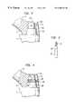
- FIG. 1is a part cross-sectional diagrammatic side elevation of a femoral component using a collarless stem for fixing in cement in a medullary cavity according to the present invention
- FIG. 2is a part cross-sectional part view of an alternative embodiment
- FIG. 3is a side elevation of a cotter pin for use in the embodiment shown in FIG. 2;
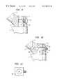
- FIG. 4is a part cross-sectional side elevation of another alternative embodiment
- FIG. 5is a part cross-sectional side elevation of another alternative embodiment using a cylindrical boss
- FIG. 6is a side elevation of a cotter pin for use with the embodiment shown in FIG. 5;
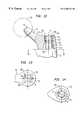
- FIG. 7is a part cross-sectional side elevation of yet another alternative embodiment
- FIG. 8is a side elevation of a cotter pin for use in the embodiment shown in FIG. 7;
- FIG. 11is a plan view of a locking plate for use in the construction shown in FIG. 10;
- FIG. 13is a partial plan view of the construction shown in FIG. 12;
- FIG. 14is a plan view on the line 14 — 14 of FIG. 12;
- FIG. 15is a view similar to FIG. 12 of an alternative embodiment.
- FIG. 16is a view similar to FIG. 15 of yet another alternative embodiment.
- the femoral componentcomprises two parts, a shoulderless stem 1 and a proximal component 2 .
- the proximal componenthas an engagement portion 3 and a neck 4 with a tapered spigot 5 to receive a ball head 6 .
- the portion 3is provided with a tapered cavity 7 which is adapted to cooperate with a tapered boss 8 provided on the proximal end of the stem 1 .
- the tapercan be a morse taper so that when pressed together the two parts tend to lock in position.
- an attachment systemwhich, in FIG. 1, comprise a screw 10 which extends through an opening 11 in the proximal component and passes into a threaded bore 12 in the tapered boss 8 .
- the screw 10carries a lock nut 13 and has a hexagonal, or other appropriately shaped head 14 .
- two especially shaped spanners 15 and 16are provided.
- the medullary cavity of the bone to which it is to be fittedis suitably prepared and lined with cement.
- the stem 1is now inserted, perhaps using an appropriate inserter, but due to the construction of the present invention, its angular position about a proximal/distal axis is not vital and it can therefore be inserted so that it can take up the best and appropriate position in the cavity. Thus, it can be positioned so that it has the maximum amount of cement about it so that it is riot close to any of the cavity walls.
- the proximal componentWith the stem located in the cavity, the proximal component can be carefully fitted so that it projects angularly about the proximal/distal axis as is required. In order to hold the tapers in position it may be necessary to deliver a light blow in the proximal/distal axis direction to ensure that the tapers seat and grip.
- the screw 10is now inserted to a marked position where it is known that there is sufficient thread within the boss 8 .
- the locking screw 13is now initially gently tightened down by hand and the spanner wrenches 15 and 16 are now employed to ensure that the screw 10 between the tapered boss 8 and the top of the portion 3 is pulled up tightly to again ensure that the tapers hold.
- the spanner 15is used to hold the screw head 14 and prevent rotation and the spanner is employed to tighten the nut 13 . Due to the juxtaposition of the spanners this can be achieved without applying any torsion to the stem 1 and thus prevents inadvertent movement of the possibility of loosening the stem in the rapidly drying cement.
- the spannersare, of course, removed after the femoral component and the stem have been locked together.
- the screwmay be removed, as required, without altering the engagement of the tapers.
- FIGS. 2 and 3show an alternative construction again using a tapered boss and the same reference numerals are used to indicate similar parts as in FIG. 1 .
- the tapered bossis indicated by reference numeral 20 and has a cylindrical extension 21 .
- the proximal component 2is again provided with a tapered socket 22 which in this construction extends upwardly as a cylindrical opening 23 .
- the releasable meansincludes a cotter pin 24 as shown in FIG. 3 .
- This cotter pinhas a flat side 25 and is shaped to pass through a hole 26 provided in the portion 3 and shaped so that the flat side of the tapered pin 24 engages the cylindrical extension 21 , the flat side being tangential to the extension.
- the stemis inserted as described with regard to FIG. 1 and the proximal component again placed in position.
- the cotter pinis inserted through the opening 26 and tightened by a nut (not shown) on a threaded portion 27 . This pulls the cotter pin through on its taper firmly engaging it with the extension 21 .
- FIG. 4the same reference numerals are again used to indicate similar part to those shown in FIG. 1 but in this construction an extended tapered boss 30 is used and the socket 32 extends through the portion 3 .
- the tapered boss 30has a groove 33 which is lined with a bonded synthetic plastics material indicated by reference numeral 34 .
- the portion 3has a threaded opening 35 to receive a set screw 36 .
- the partsare again assembled together in the manner described with regard to the previous figures and the releasable locking system is provided by tightening the screw 36 which extends substantially radially to the proximal/distal axis.
- FIGS. 5 and 6show another embodiment according to the invention in which the same reference numerals are again used as those employed in FIG. 1 to indicate similar parts but in this construction the tapered boss of FIGS. 1 and 4 is replaced by a cylindrical boss 40 which extends through an open socket 41 in the proximal component.
- a cotter pin 42is again employed, this having a flat side 43 and a threaded end 44 .
- the portion 3is provided with a suitably shaped opening 40 ′ to receive the pin which is inserted and locking in position in a similar manner to that described with regard to FIG. 2 .
- FIGS. 7 and 8also show a construction in which a cotter pin is used but in this arrangement the cylindrical boss 50 is provided with a peripheral groove 51 into which a tapered cotter pin 52 can extend.
- the cotter pinhas a cylindrical tapered shank 53 and is provided with a threaded end 54 .
- the pinis passed through an opening 55 in the portion 3 , one side of the pin engaging the opening 55 and the other engaging in the groove 51 . Once again, it is locked in position by means of a screw on the thread 54 .
- FIG. 9shows another construction using a boss with a groove 51 similar to that shown in FIG. 7 but in this construction the cotter pin is replaced by a locking screw 57 which engages the groove by passing through a threaded opening 58 in the portion 3 .
- FIGS. 10 and 11show another construction in which a boss 50 is provided with a groove 51 but the screw 57 of FIG. 9 is replaced by a locking plate 60 .
- This plate 60has a central opening 61 and is located in a slot 62 in the portion 3 .
- the plateis provided with a projecting screw 63 on which is located a tightening nut 64 . It will be seen from FIG. 1 that the inner edges of the opening 61 are bevelled to accurately locate in the groove 51 .
- the plateis located in position in the slot 62 before the proximal component is placed on the boss 50 , the angular position is carefully located and the boss is held in position by tightening up the nut 64 which pulls the plate into a position where it can lock against the groove 51 .
- the femoral component according to the inventioncomprises a Vernier coupling provided by a ring of openings 80 in a proximal component 72 .
- the openings 80are arranged on a radius r about a proximal/distal axis A.
- a second ring of openings 81are provided on a stem 71 and are arranged on the same radius r about the same axis A as the openings 80 in the proximal component. These openings 81 extend into the wall of a boss 78 whilst the openings 80 are arranged to open through a proximal surface 82 of the proximal component surrounding the open end of a tapered cavity 77 . As will be seen from FIG. 12, the distal end of the openings 80 extend into the tapered cavity 72 at a position in line with the proximal ends of the openings 81 in the boss and the distal end 83 of each of the openings 81 is towards the distal end of the boss.
- a locating pin 84 having a head 85is provided which is a push or tight fit in the openings 81 .
- the openings 81are threaded and the pin 84 is replaced by a screw which can engage the thread.
- the Vernier effectis created in the construction shown in FIG. 12 by providing six openings 80 and seven openings 81 . This allows small increments of angular adjustment between the proximal component and the stem 71 .
- any pressure placed on the femoral componentis in direction of the proximal/distal axis. If a screw is used, then any torsional twisting movement of the stem when the proximal component is fitted need only be very light.
- a medullary cavityis prepared in the usual way and the stem 1 is first inserted, being allowed to take up any angular position about a proximal/distal axis as is desired by the surgeon, thus enabling the maximum cement mantle to be achieved.
- the proximal componentis now fitted and the correct angle assessed by the surgeon, the very small increments of angular movement allowing good accuracy.
- the pin 84 or screwcan be lightly inserted and then the femoral component tapped or have pressure applied to ensure that the taper between the boss and the cavity locks.
- the pin or screw 84is now driven fully home thus ensuring that the proximal component and the stem are firmly locked together.
- FIG. 15An alternative embodiment is shown in FIG. 15 and the same reference numerals are used to indicate similar parts.
- a cylindrical boss 90is employed on the stem 71 and is a close sliding fit in a cylindrical cavity 91 in the proximal component 72 .
- the end of the cavity 91is closed and the end wall is provided with a ring of openings 92 which are again around a fixed radius based on a proximal/distal axis A.
- a further ring of openings 93are provided in the proximal end of the boss 90 which are again on the same radius and about the same axis A.
- a Vernier couplingis provided by the insertion of a pin or screw 94 into an appropriate pair of mating holes at the desired angular position.
- FIG. 16shows another alternative construction again employing the same reference numerals to indicate similar parts.
- a cylindrical boss 90is again shown but this carries a ring of blind openings 95 which are aligned in a plane B with a second ring of openings 96 provided in the proximal component 72 .
- This arrangementcould also be employed with a tapered boss and cavity of the kind shown in FIG. 12 .
Landscapes
- Health & Medical Sciences (AREA)
- Orthopedic Medicine & Surgery (AREA)
- Cardiology (AREA)
- Oral & Maxillofacial Surgery (AREA)
- Transplantation (AREA)
- Engineering & Computer Science (AREA)
- Biomedical Technology (AREA)
- Heart & Thoracic Surgery (AREA)
- Vascular Medicine (AREA)
- Life Sciences & Earth Sciences (AREA)
- Animal Behavior & Ethology (AREA)
- General Health & Medical Sciences (AREA)
- Public Health (AREA)
- Veterinary Medicine (AREA)
- Prostheses (AREA)
Abstract
Description
Claims (24)
Applications Claiming Priority (4)
| Application Number | Priority Date | Filing Date | Title |
|---|---|---|---|
| GB9828084 | 1998-12-18 | ||
| GBGB9828084.5AGB9828084D0 (en) | 1998-12-18 | 1998-12-18 | Femoral component |
| GB9828085 | 1998-12-18 | ||
| GBGB9828085.2AGB9828085D0 (en) | 1998-12-18 | 1998-12-18 | Femoral component |
Publications (1)
| Publication Number | Publication Date |
|---|---|
| US6306174B1true US6306174B1 (en) | 2001-10-23 |
Family
ID=26314875
Family Applications (1)
| Application Number | Title | Priority Date | Filing Date |
|---|---|---|---|
| US09/464,580Expired - LifetimeUS6306174B1 (en) | 1998-12-18 | 1999-12-16 | Femoral component |
Country Status (1)
| Country | Link |
|---|---|
| US (1) | US6306174B1 (en) |
Cited By (41)
| Publication number | Priority date | Publication date | Assignee | Title |
|---|---|---|---|---|
| US20020128720A1 (en)* | 1999-10-01 | 2002-09-12 | Masini Michael A. | Anti-impingement femoral prostheses |
| US20030074079A1 (en)* | 1998-04-14 | 2003-04-17 | Osteoimplant Technology, Inc. | Differential porosity prosthetic hip system |
| US20030204266A1 (en)* | 2002-04-25 | 2003-10-30 | Medicinelodge, Inc. | Modular prosthesis for replacing bone and method |
| US20040010319A1 (en)* | 1998-04-14 | 2004-01-15 | Osteoimplant Technology Inc. | Intrinsic stability in a total hip stem |
| US20050049710A1 (en)* | 2003-08-28 | 2005-03-03 | O'driscoll Shawn W. | Prosthesis for partial replacement of an articulating surface on bone |
| US6866683B2 (en) | 2002-12-13 | 2005-03-15 | Medicine Lodge, Inc. | Modular implant for joint reconstruction and method of use |
| US6887276B2 (en) | 2002-12-13 | 2005-05-03 | Medicine Lodge, Inc | Modular implant for joint reconstruction and method of use |
| US6902583B2 (en) | 2002-04-25 | 2005-06-07 | Medicinelodge, Inc. | Tripartite attachment mechanism and method for a modular prosthesis |
| US20050216090A1 (en)* | 2004-03-11 | 2005-09-29 | O'driscoll Shawn W | Systems for bone replacement |
| US7135044B2 (en) | 2004-03-09 | 2006-11-14 | Howmedics Osteonics Corp. | Modular prosthesis kits |
| US7179259B1 (en) | 2004-06-04 | 2007-02-20 | Biomet Manufacturing Corp. | Instrument assembly for lateral implant |
| WO2008106254A3 (en)* | 2007-01-24 | 2009-07-30 | Musculoskeletal Transplant | Two piece cancellous construct for cartilage repair |
| WO2009076164A3 (en)* | 2007-12-05 | 2009-08-20 | Musculoskeletal Transplant | Cancellous bone implant for cartilage repair |
| US7641698B1 (en) | 2004-06-04 | 2010-01-05 | Biomet Manufacturing Corp. | Modular hip joint implant |
| US7815926B2 (en) | 2005-07-11 | 2010-10-19 | Musculoskeletal Transplant Foundation | Implant for articular cartilage repair |
| US20100318191A1 (en)* | 2009-06-12 | 2010-12-16 | Branovacki George | Joint implant |
| US7857858B2 (en) | 2002-04-25 | 2010-12-28 | Zimmer Technology, Inc. | Modular bone implant, tool, and method |
| USRE42208E1 (en) | 2003-04-29 | 2011-03-08 | Musculoskeletal Transplant Foundation | Glue for cartilage repair |
| US7901457B2 (en) | 2003-05-16 | 2011-03-08 | Musculoskeletal Transplant Foundation | Cartilage allograft plug |
| US7914584B2 (en) | 2004-10-21 | 2011-03-29 | Biomet Manufacturing Corp. | Prosthesis system with trunnion and removably coupled head |
| US20110218582A1 (en)* | 2010-03-05 | 2011-09-08 | Biomet Manufacturing Corp. | Method and Apparatus for Implanting a Modular Femoral Hip |
| US20110218636A1 (en)* | 2010-03-05 | 2011-09-08 | Biomet Manufacturing Corp. | Guide Assembly for Lateral Implants and Associated Methods |
| US20110218583A1 (en)* | 2010-03-05 | 2011-09-08 | Biomet Manufacturing Corp. | Assembly Tool for Modular Implants and Associated Method |
| US20110218641A1 (en)* | 2010-03-05 | 2011-09-08 | Biomet Manufacturing Corp. | Modular Lateral Hip Augments |
| US20110218537A1 (en)* | 2010-03-05 | 2011-09-08 | Biomet Manufacturing Corp. | Method and Apparatus for Preparing a Proximal Femur |
| US20110218640A1 (en)* | 2010-03-05 | 2011-09-08 | Biomet Manufacturing Corp. | Method and Apparatus for Trialing and Implanting a Modular Femoral Hip |
| US20110224798A1 (en)* | 2010-03-09 | 2011-09-15 | James Thompson Caillouette | Hip replacement process |
| WO2012030409A1 (en)* | 2010-09-03 | 2012-03-08 | Caillouette James T | Hip replacement process |
| US20120123553A1 (en)* | 2010-11-11 | 2012-05-17 | Sidebotham Christopher G | Joint implant fixation system |
| US8292968B2 (en) | 2004-10-12 | 2012-10-23 | Musculoskeletal Transplant Foundation | Cancellous constructs, cartilage particles and combinations of cancellous constructs and cartilage particles |
| ITMI20110782A1 (en)* | 2011-05-09 | 2012-11-10 | Adler Ortho S R L | ARTHROPROSTANCES PERFECTED WITH FACILITATED SYSTEM, PARTICULARLY FOR THE BIOMECHANICAL RECONSTRUCTION OF THE COXOPHEMORAL ARTICULATION. |
| US8435551B2 (en) | 2007-03-06 | 2013-05-07 | Musculoskeletal Transplant Foundation | Cancellous construct with support ring for repair of osteochondral defects |
| US20130304225A1 (en)* | 2012-05-08 | 2013-11-14 | Richard D. Komistek | Optimal contact mechanics for a tha |
| US20150190233A1 (en)* | 2012-07-26 | 2015-07-09 | Waldemar Link Gmbh & Co. Kg | Plug-on module for a long shaft prosthesis |
| US9155626B2 (en) | 2012-09-10 | 2015-10-13 | Acumed Llc | Radial head prosthesis with floating articular member |
| US9427322B1 (en)* | 2012-06-27 | 2016-08-30 | Signal Medical Corporation | Hip implant |
| US9701940B2 (en) | 2005-09-19 | 2017-07-11 | Histogenics Corporation | Cell-support matrix having narrowly defined uniformly vertically and non-randomly organized porosity and pore density and a method for preparation thereof |
| US9763792B2 (en) | 2015-10-01 | 2017-09-19 | Acumed Llc | Radial head prosthesis with rotate-to-lock interface |
| EP3332747A1 (en)* | 2016-12-09 | 2018-06-13 | Jooss, Armin | Hip joint endoprosthesis system |
| US10077420B2 (en) | 2014-12-02 | 2018-09-18 | Histogenics Corporation | Cell and tissue culture container |
| US20230081046A1 (en)* | 2017-08-22 | 2023-03-16 | Depuy Ireland Unlimited Company | Trial neck |
Citations (10)
| Publication number | Priority date | Publication date | Assignee | Title |
|---|---|---|---|---|
| US3067740A (en)* | 1959-09-08 | 1962-12-11 | Edward J Haboush | Hip joint prosthesis |
| GB1409054A (en) | 1971-09-24 | 1975-10-08 | Nat Res Dev | Hip joint prosthesis |
| US4051559A (en) | 1974-12-27 | 1977-10-04 | Mahay & Cie | Total prosthesis of the hip |
| US5002578A (en)* | 1990-05-04 | 1991-03-26 | Venus Corporation | Modular hip stem prosthesis apparatus and method |
| US5201882A (en)* | 1989-11-03 | 1993-04-13 | Paxson Robert D | Modular hip joint prosthesis with adjustable anteversion |
| US5286260A (en)* | 1986-08-15 | 1994-02-15 | Depuy Inc. | Modular hip prosthesis |
| US5702479A (en)* | 1993-02-18 | 1997-12-30 | Schawalder; Peter | Shaft component for a joint endoprosthesis |
| US5858020A (en)* | 1995-12-05 | 1999-01-12 | Metagen, Llc | Modular prosthesis |
| US5931871A (en) | 1993-10-21 | 1999-08-03 | Allo Pro Ag | Kit of parts for a modular femur head prosthesis, in particular, a reoperation prosthesis, and a femur head prosthesis from such a kit of parts |
| US6083263A (en)* | 1991-08-23 | 2000-07-04 | Draenert; Klaus | Adjustable hip-joint endoprosthesis |
- 1999
- 1999-12-16USUS09/464,580patent/US6306174B1/ennot_activeExpired - Lifetime
Patent Citations (10)
| Publication number | Priority date | Publication date | Assignee | Title |
|---|---|---|---|---|
| US3067740A (en)* | 1959-09-08 | 1962-12-11 | Edward J Haboush | Hip joint prosthesis |
| GB1409054A (en) | 1971-09-24 | 1975-10-08 | Nat Res Dev | Hip joint prosthesis |
| US4051559A (en) | 1974-12-27 | 1977-10-04 | Mahay & Cie | Total prosthesis of the hip |
| US5286260A (en)* | 1986-08-15 | 1994-02-15 | Depuy Inc. | Modular hip prosthesis |
| US5201882A (en)* | 1989-11-03 | 1993-04-13 | Paxson Robert D | Modular hip joint prosthesis with adjustable anteversion |
| US5002578A (en)* | 1990-05-04 | 1991-03-26 | Venus Corporation | Modular hip stem prosthesis apparatus and method |
| US6083263A (en)* | 1991-08-23 | 2000-07-04 | Draenert; Klaus | Adjustable hip-joint endoprosthesis |
| US5702479A (en)* | 1993-02-18 | 1997-12-30 | Schawalder; Peter | Shaft component for a joint endoprosthesis |
| US5931871A (en) | 1993-10-21 | 1999-08-03 | Allo Pro Ag | Kit of parts for a modular femur head prosthesis, in particular, a reoperation prosthesis, and a femur head prosthesis from such a kit of parts |
| US5858020A (en)* | 1995-12-05 | 1999-01-12 | Metagen, Llc | Modular prosthesis |
Cited By (77)
| Publication number | Priority date | Publication date | Assignee | Title |
|---|---|---|---|---|
| US20030074079A1 (en)* | 1998-04-14 | 2003-04-17 | Osteoimplant Technology, Inc. | Differential porosity prosthetic hip system |
| US20040010319A1 (en)* | 1998-04-14 | 2004-01-15 | Osteoimplant Technology Inc. | Intrinsic stability in a total hip stem |
| US7323013B2 (en) | 1998-04-14 | 2008-01-29 | Encore Medical Asset Corporation | Differential porosity prosthetic hip system |
| USRE44803E1 (en) | 1999-10-01 | 2014-03-11 | Medidea, Llc | Anti-impingement femoral prostheses |
| US7985261B2 (en) | 1999-10-01 | 2011-07-26 | Medidea, Llc | Anti-impingement femoral prostheses |
| US20020128720A1 (en)* | 1999-10-01 | 2002-09-12 | Masini Michael A. | Anti-impingement femoral prostheses |
| US6875239B2 (en) | 2002-04-25 | 2005-04-05 | Medicinelodge, Inc. | Modular prosthesis for replacing bone and method |
| US8241367B2 (en) | 2002-04-25 | 2012-08-14 | Zimmer, Inc. | Modular bone implant, tool, and method |
| US6902583B2 (en) | 2002-04-25 | 2005-06-07 | Medicinelodge, Inc. | Tripartite attachment mechanism and method for a modular prosthesis |
| US20030204266A1 (en)* | 2002-04-25 | 2003-10-30 | Medicinelodge, Inc. | Modular prosthesis for replacing bone and method |
| US7857858B2 (en) | 2002-04-25 | 2010-12-28 | Zimmer Technology, Inc. | Modular bone implant, tool, and method |
| US6887276B2 (en) | 2002-12-13 | 2005-05-03 | Medicine Lodge, Inc | Modular implant for joint reconstruction and method of use |
| US6866683B2 (en) | 2002-12-13 | 2005-03-15 | Medicine Lodge, Inc. | Modular implant for joint reconstruction and method of use |
| USRE42208E1 (en) | 2003-04-29 | 2011-03-08 | Musculoskeletal Transplant Foundation | Glue for cartilage repair |
| USRE43258E1 (en) | 2003-04-29 | 2012-03-20 | Musculoskeletal Transplant Foundation | Glue for cartilage repair |
| US7901457B2 (en) | 2003-05-16 | 2011-03-08 | Musculoskeletal Transplant Foundation | Cartilage allograft plug |
| US8221500B2 (en) | 2003-05-16 | 2012-07-17 | Musculoskeletal Transplant Foundation | Cartilage allograft plug |
| US20050049710A1 (en)* | 2003-08-28 | 2005-03-03 | O'driscoll Shawn W. | Prosthesis for partial replacement of an articulating surface on bone |
| US7135044B2 (en) | 2004-03-09 | 2006-11-14 | Howmedics Osteonics Corp. | Modular prosthesis kits |
| US7608110B2 (en) | 2004-03-11 | 2009-10-27 | O'driscoll Shawn W | Systems for bone replacement |
| US20050216090A1 (en)* | 2004-03-11 | 2005-09-29 | O'driscoll Shawn W | Systems for bone replacement |
| US20100114324A1 (en)* | 2004-06-04 | 2010-05-06 | Biomet Manufacturing Corp. | Modular Hip Joint Implant |
| US7641698B1 (en) | 2004-06-04 | 2010-01-05 | Biomet Manufacturing Corp. | Modular hip joint implant |
| US8066779B2 (en) | 2004-06-04 | 2011-11-29 | Biomet Manufacturing Corp. | Modular hip joint implant |
| US7179259B1 (en) | 2004-06-04 | 2007-02-20 | Biomet Manufacturing Corp. | Instrument assembly for lateral implant |
| US8292968B2 (en) | 2004-10-12 | 2012-10-23 | Musculoskeletal Transplant Foundation | Cancellous constructs, cartilage particles and combinations of cancellous constructs and cartilage particles |
| US7914584B2 (en) | 2004-10-21 | 2011-03-29 | Biomet Manufacturing Corp. | Prosthesis system with trunnion and removably coupled head |
| US7815926B2 (en) | 2005-07-11 | 2010-10-19 | Musculoskeletal Transplant Foundation | Implant for articular cartilage repair |
| US9701940B2 (en) | 2005-09-19 | 2017-07-11 | Histogenics Corporation | Cell-support matrix having narrowly defined uniformly vertically and non-randomly organized porosity and pore density and a method for preparation thereof |
| US8906110B2 (en) | 2007-01-24 | 2014-12-09 | Musculoskeletal Transplant Foundation | Two piece cancellous construct for cartilage repair |
| US7837740B2 (en) | 2007-01-24 | 2010-11-23 | Musculoskeletal Transplant Foundation | Two piece cancellous construct for cartilage repair |
| WO2008106254A3 (en)* | 2007-01-24 | 2009-07-30 | Musculoskeletal Transplant | Two piece cancellous construct for cartilage repair |
| US8435551B2 (en) | 2007-03-06 | 2013-05-07 | Musculoskeletal Transplant Foundation | Cancellous construct with support ring for repair of osteochondral defects |
| WO2009076164A3 (en)* | 2007-12-05 | 2009-08-20 | Musculoskeletal Transplant | Cancellous bone implant for cartilage repair |
| US20100318191A1 (en)* | 2009-06-12 | 2010-12-16 | Branovacki George | Joint implant |
| US8066775B2 (en) | 2009-06-12 | 2011-11-29 | Branovacki George | Joint implant |
| US8221432B2 (en) | 2010-03-05 | 2012-07-17 | Biomet Manufacturing Corp. | Method and apparatus for implanting a modular femoral hip |
| US8906109B2 (en) | 2010-03-05 | 2014-12-09 | Biomet Manufacturing, Llc | Modular lateral hip augments |
| US10188520B2 (en) | 2010-03-05 | 2019-01-29 | Biomet Manufacturing, Llc | Modular lateral hip augments |
| US20110218582A1 (en)* | 2010-03-05 | 2011-09-08 | Biomet Manufacturing Corp. | Method and Apparatus for Implanting a Modular Femoral Hip |
| US20110218640A1 (en)* | 2010-03-05 | 2011-09-08 | Biomet Manufacturing Corp. | Method and Apparatus for Trialing and Implanting a Modular Femoral Hip |
| US20110218537A1 (en)* | 2010-03-05 | 2011-09-08 | Biomet Manufacturing Corp. | Method and Apparatus for Preparing a Proximal Femur |
| US9615942B2 (en) | 2010-03-05 | 2017-04-11 | Biomet Manufacturing, Llc | Method and apparatus for trialing and implanting a modular femoral hip |
| US9510950B2 (en) | 2010-03-05 | 2016-12-06 | Biomet Manufacturing, Llc | Modular lateral hip auguments |
| US8333807B2 (en)* | 2010-03-05 | 2012-12-18 | Biomet Manufacturing Corp. | Method and apparatus for trialing and implanting a modular femoral hip |
| US8419743B2 (en) | 2010-03-05 | 2013-04-16 | Biomet Manufacturing Corp. | Assembly tool for modular implants and associated method |
| US9339318B2 (en) | 2010-03-05 | 2016-05-17 | Biomet Manufacturing, Llc | Method and apparatus for preparing a proximal femur |
| US20110218641A1 (en)* | 2010-03-05 | 2011-09-08 | Biomet Manufacturing Corp. | Modular Lateral Hip Augments |
| US8460393B2 (en) | 2010-03-05 | 2013-06-11 | Biomet Manufacturing Corp. | Modular lateral hip augments |
| US8529569B2 (en) | 2010-03-05 | 2013-09-10 | Biomet Manufacturing, Llc | Method and apparatus for preparing a proximal femur |
| US9314287B2 (en) | 2010-03-05 | 2016-04-19 | Biomet Manufacturing, Llc | Assembly tool for modular implant and associated method |
| US8591518B2 (en) | 2010-03-05 | 2013-11-26 | Biomet Manufacturing, Llc | Method and apparatus for implanting a modular femoral hip |
| US9138273B2 (en) | 2010-03-05 | 2015-09-22 | Biomet Manufacturing, Llc | Guide assembly for lateral implants and associated methods |
| US20110218583A1 (en)* | 2010-03-05 | 2011-09-08 | Biomet Manufacturing Corp. | Assembly Tool for Modular Implants and Associated Method |
| US8679130B2 (en) | 2010-03-05 | 2014-03-25 | Biomet Manufacturing, Llc | Guide assembly for lateral implants and associated methods |
| US8876837B2 (en) | 2010-03-05 | 2014-11-04 | Biomet Manufacturing, Llc | Method and apparatus for implanting a modular femoral hip |
| US20110218636A1 (en)* | 2010-03-05 | 2011-09-08 | Biomet Manufacturing Corp. | Guide Assembly for Lateral Implants and Associated Methods |
| US20110224798A1 (en)* | 2010-03-09 | 2011-09-15 | James Thompson Caillouette | Hip replacement process |
| US8425618B2 (en) | 2010-03-09 | 2013-04-23 | James Thompson Caillouette | Hip replacement process |
| WO2012030409A1 (en)* | 2010-09-03 | 2012-03-08 | Caillouette James T | Hip replacement process |
| US20120123553A1 (en)* | 2010-11-11 | 2012-05-17 | Sidebotham Christopher G | Joint implant fixation system |
| US8597361B2 (en)* | 2010-11-11 | 2013-12-03 | Bioshift, Llc | Joint implant fixation system |
| ITMI20110782A1 (en)* | 2011-05-09 | 2012-11-10 | Adler Ortho S R L | ARTHROPROSTANCES PERFECTED WITH FACILITATED SYSTEM, PARTICULARLY FOR THE BIOMECHANICAL RECONSTRUCTION OF THE COXOPHEMORAL ARTICULATION. |
| WO2012152464A1 (en)* | 2011-05-09 | 2012-11-15 | Adler Ortho S.R.L. | Arthroprosthesis with facilitated implantation, particularly for biomechanical reconstruction of the coxofemoral joint |
| AU2018204697B2 (en)* | 2012-05-08 | 2020-06-04 | Depuy Ireland Unlimited Company | Optimal contact mechanics for a tha |
| US20130304225A1 (en)* | 2012-05-08 | 2013-11-14 | Richard D. Komistek | Optimal contact mechanics for a tha |
| US9427322B1 (en)* | 2012-06-27 | 2016-08-30 | Signal Medical Corporation | Hip implant |
| US20150190233A1 (en)* | 2012-07-26 | 2015-07-09 | Waldemar Link Gmbh & Co. Kg | Plug-on module for a long shaft prosthesis |
| US9504580B2 (en)* | 2012-07-26 | 2016-11-29 | Waldemar Link Gmbh & Co. Kg | Plug-on module for a long shaft prosthesis |
| US9707084B2 (en) | 2012-09-10 | 2017-07-18 | Acumed Llc | Radial head prosthesis with floating articular member |
| US9155626B2 (en) | 2012-09-10 | 2015-10-13 | Acumed Llc | Radial head prosthesis with floating articular member |
| US10077420B2 (en) | 2014-12-02 | 2018-09-18 | Histogenics Corporation | Cell and tissue culture container |
| US11555172B2 (en) | 2014-12-02 | 2023-01-17 | Ocugen, Inc. | Cell and tissue culture container |
| US9763792B2 (en) | 2015-10-01 | 2017-09-19 | Acumed Llc | Radial head prosthesis with rotate-to-lock interface |
| EP3332747A1 (en)* | 2016-12-09 | 2018-06-13 | Jooss, Armin | Hip joint endoprosthesis system |
| US20230081046A1 (en)* | 2017-08-22 | 2023-03-16 | Depuy Ireland Unlimited Company | Trial neck |
| US12226324B2 (en)* | 2017-08-22 | 2025-02-18 | Depuy Ireland Unlimited Company, Loughbeg Industrial Estate | Trial neck |
Similar Documents
| Publication | Publication Date | Title |
|---|---|---|
| US6306174B1 (en) | Femoral component | |
| US5800553A (en) | Hip joint prosthesis to be permanently anchored within a femur of a patient | |
| US6299648B1 (en) | Locking hip prosthesis | |
| EP2856974B1 (en) | Distal reamer | |
| US5580352A (en) | Distal shaft with fast and slow screw threads | |
| AU2003266447B2 (en) | Modular hip stems and associated method of trialing | |
| US4051559A (en) | Total prosthesis of the hip | |
| US7491242B2 (en) | Femoral prosthesis | |
| US8632603B2 (en) | Implant positioning systems for orienting prosthesis | |
| US20030114933A1 (en) | Shoulder prosthesis assembly | |
| US20090240256A1 (en) | Method And Apparatus For Implanting an Augment | |
| AU3654193A (en) | Hip joint prosthesis | |
| US6371991B1 (en) | Alignment guide for fluted prosthetic stems | |
| EP1013242A2 (en) | Femoral component | |
| US20250186213A1 (en) | Modular endoprosthesis shaft system with rotation element | |
| EP1013245B1 (en) | Femoral component | |
| US4904268A (en) | Prosthetic device | |
| EP4622600A1 (en) | Prosthetic trial device |
Legal Events
| Date | Code | Title | Description |
|---|---|---|---|
| AS | Assignment | Owner name:BENOIST GIRARD, SAS, FRANCE Free format text:ASSIGNMENT OF ASSIGNORS INTEREST;ASSIGNORS:GIE, GRAHAM ALLAN;LING, ROBIN SYDNEY MACKWOOD;STORER, JOHN ANDREW;AND OTHERS;REEL/FRAME:010753/0665;SIGNING DATES FROM 20000211 TO 20000322 | |
| STCF | Information on status: patent grant | Free format text:PATENTED CASE | |
| CC | Certificate of correction | ||
| FPAY | Fee payment | Year of fee payment:4 | |
| FPAY | Fee payment | Year of fee payment:8 | |
| AS | Assignment | Owner name:STRYKER IRELAND LIMITED, IRELAND Free format text:CONFIRMATORY LICENSE;ASSIGNOR:BENOIST GIRARD SAS;REEL/FRAME:029674/0420 Effective date:20121126 Owner name:STRYKER IRELAND LIMITED, IRELAND Free format text:CONFIRMATORY ASSIGNMENT;ASSIGNOR:BENOIST GIRARD SAS;REEL/FRAME:029674/0420 Effective date:20121126 | |
| FPAY | Fee payment | Year of fee payment:12 | |
| AS | Assignment | Owner name:STRYKER EUROPEAN HOLDINGS I, LLC, MICHIGAN Free format text:NUNC PRO TUNC ASSIGNMENT;ASSIGNOR:STRYKER MEDTECH LIMITED;REEL/FRAME:037153/0241 Effective date:20151013 Owner name:STRYKER MEDTECH LIMITED, MALTA Free format text:NUNC PRO TUNC ASSIGNMENT;ASSIGNOR:STRYKER IRELAND LIMITED;REEL/FRAME:037152/0946 Effective date:20151013 | |
| AS | Assignment | Owner name:STRYKER EUROPEAN HOLDINGS I, LLC, MICHIGAN Free format text:CORRECTIVE ASSIGNMENT TO CORRECT THE INCORRECT LISTED SERIAL NOS. 09/905,670 AND 07/092,079 PREVIOUSLY RECORDED AT REEL: 037153 FRAME: 0241. ASSIGNOR(S) HEREBY CONFIRMS THE NUNC PRO TUNC ASSIGNMENT EFFECTIVE DATE 9/29/2014;ASSIGNOR:STRYKER MEDTECH LIMITED;REEL/FRAME:038043/0011 Effective date:20151013 | |
| AS | Assignment | Owner name:STRYKER EUROPEAN OPERATIONS HOLDINGS LLC, MICHIGAN Free format text:CHANGE OF NAME;ASSIGNOR:STRYKER EUROPEAN HOLDINGS III, LLC;REEL/FRAME:052860/0716 Effective date:20190226 Owner name:STRYKER EUROPEAN HOLDINGS III, LLC, DELAWARE Free format text:NUNC PRO TUNC ASSIGNMENT;ASSIGNOR:STRYKER EUROPEAN HOLDINGS I, LLC;REEL/FRAME:052861/0001 Effective date:20200519 |