US6306139B1 - Intervertebral connection device with an anti-extraction device to prevent extraction of anchoring screws - Google Patents
Intervertebral connection device with an anti-extraction device to prevent extraction of anchoring screwsDownload PDFInfo
- Publication number
- US6306139B1 US6306139B1US09/271,287US27128799AUS6306139B1US 6306139 B1US6306139 B1US 6306139B1US 27128799 AUS27128799 AUS 27128799AUS 6306139 B1US6306139 B1US 6306139B1
- Authority
- US
- United States
- Prior art keywords
- plate
- mobile flap
- connection device
- bores
- intervertebral connection
- Prior art date
- Legal status (The legal status is an assumption and is not a legal conclusion. Google has not performed a legal analysis and makes no representation as to the accuracy of the status listed.)
- Expired - Lifetime
Links
- 0CC[C@]1**2C(C)(*C#C)CC2CC1Chemical compoundCC[C@]1**2C(C)(*C#C)CC2CC10.000description1
Images


Classifications
- A—HUMAN NECESSITIES
- A61—MEDICAL OR VETERINARY SCIENCE; HYGIENE
- A61B—DIAGNOSIS; SURGERY; IDENTIFICATION
- A61B17/00—Surgical instruments, devices or methods
- A61B17/56—Surgical instruments or methods for treatment of bones or joints; Devices specially adapted therefor
- A61B17/58—Surgical instruments or methods for treatment of bones or joints; Devices specially adapted therefor for osteosynthesis, e.g. bone plates, screws or setting implements
- A61B17/68—Internal fixation devices, including fasteners and spinal fixators, even if a part thereof projects from the skin
- A61B17/80—Cortical plates, i.e. bone plates; Instruments for holding or positioning cortical plates, or for compressing bones attached to cortical plates
- A61B17/8033—Cortical plates, i.e. bone plates; Instruments for holding or positioning cortical plates, or for compressing bones attached to cortical plates having indirect contact with screw heads, or having contact with screw heads maintained with the aid of additional components, e.g. nuts, wedges or head covers
- A61B17/8042—Cortical plates, i.e. bone plates; Instruments for holding or positioning cortical plates, or for compressing bones attached to cortical plates having indirect contact with screw heads, or having contact with screw heads maintained with the aid of additional components, e.g. nuts, wedges or head covers the additional component being a cover over the screw head
- A—HUMAN NECESSITIES
- A61—MEDICAL OR VETERINARY SCIENCE; HYGIENE
- A61B—DIAGNOSIS; SURGERY; IDENTIFICATION
- A61B17/00—Surgical instruments, devices or methods
- A61B17/16—Instruments for performing osteoclasis; Drills or chisels for bones; Trepans
- A61B17/17—Guides or aligning means for drills, mills, pins or wires
- A61B17/1728—Guides or aligning means for drills, mills, pins or wires for holes for bone plates or plate screws
- A—HUMAN NECESSITIES
- A61—MEDICAL OR VETERINARY SCIENCE; HYGIENE
- A61B—DIAGNOSIS; SURGERY; IDENTIFICATION
- A61B17/00—Surgical instruments, devices or methods
- A61B17/16—Instruments for performing osteoclasis; Drills or chisels for bones; Trepans
- A61B17/17—Guides or aligning means for drills, mills, pins or wires
- A61B17/1739—Guides or aligning means for drills, mills, pins or wires specially adapted for particular parts of the body
- A61B17/1757—Guides or aligning means for drills, mills, pins or wires specially adapted for particular parts of the body for the spine
- A—HUMAN NECESSITIES
- A61—MEDICAL OR VETERINARY SCIENCE; HYGIENE
- A61B—DIAGNOSIS; SURGERY; IDENTIFICATION
- A61B17/00—Surgical instruments, devices or methods
- A61B17/56—Surgical instruments or methods for treatment of bones or joints; Devices specially adapted therefor
- A61B17/58—Surgical instruments or methods for treatment of bones or joints; Devices specially adapted therefor for osteosynthesis, e.g. bone plates, screws or setting implements
- A61B17/68—Internal fixation devices, including fasteners and spinal fixators, even if a part thereof projects from the skin
- A61B17/70—Spinal positioners or stabilisers, e.g. stabilisers comprising fluid filler in an implant
- A—HUMAN NECESSITIES
- A61—MEDICAL OR VETERINARY SCIENCE; HYGIENE
- A61B—DIAGNOSIS; SURGERY; IDENTIFICATION
- A61B17/00—Surgical instruments, devices or methods
- A61B17/56—Surgical instruments or methods for treatment of bones or joints; Devices specially adapted therefor
- A61B17/58—Surgical instruments or methods for treatment of bones or joints; Devices specially adapted therefor for osteosynthesis, e.g. bone plates, screws or setting implements
- A61B17/68—Internal fixation devices, including fasteners and spinal fixators, even if a part thereof projects from the skin
- A61B17/80—Cortical plates, i.e. bone plates; Instruments for holding or positioning cortical plates, or for compressing bones attached to cortical plates
- A61B17/808—Instruments for holding or positioning bone plates, or for adjusting screw-to-plate locking mechanisms
- A—HUMAN NECESSITIES
- A61—MEDICAL OR VETERINARY SCIENCE; HYGIENE
- A61B—DIAGNOSIS; SURGERY; IDENTIFICATION
- A61B17/00—Surgical instruments, devices or methods
- A61B2017/0046—Surgical instruments, devices or methods with a releasable handle; with handle and operating part separable
- Y—GENERAL TAGGING OF NEW TECHNOLOGICAL DEVELOPMENTS; GENERAL TAGGING OF CROSS-SECTIONAL TECHNOLOGIES SPANNING OVER SEVERAL SECTIONS OF THE IPC; TECHNICAL SUBJECTS COVERED BY FORMER USPC CROSS-REFERENCE ART COLLECTIONS [XRACs] AND DIGESTS
- Y10—TECHNICAL SUBJECTS COVERED BY FORMER USPC
- Y10S—TECHNICAL SUBJECTS COVERED BY FORMER USPC CROSS-REFERENCE ART COLLECTIONS [XRACs] AND DIGESTS
- Y10S606/00—Surgery
- Y10S606/902—Cortical plate specifically adapted for a particular bone
Definitions
- the present inventionrelates to intervertebral connection devices designed to correct a weakening, a fracture of the vertebrae, or a defective posture of the spine.
- Itrelates more precisely to devices for connecting the cervical vertebrae, preferably intended to be fixed on their anterior face.
- An anterior intervertebral connection devicegenerally comprises a rigid osteosynthesis plate adapted to cover at least partially two consecutive vertebrae, in order to join them together.
- This osteosynthesis platepresents an anterior face and an opposite posterior face intended to be applied against the anterior face of the vertebrae.
- This plateis generally provided with two pairs of through holes, designed each to receive a screw intended to be anchored in the body of the vertebrae.
- document FR 2 740 321has proposed an osteosynthesis device comprising, as means preventing extraction of the screws, a rigid counter-plate intended to be fixed on the anterior face of the osteosynthesis plate.
- the shape of this counter-plateis substantially similar to that of the osteosynthesis plate, so as to totally to cover all the anchoring screw heads.
- the counter-plateis fixed on the osteosynthesis plate with the aid of a screw adapted to screw in a tapping made on the osteosynthesis plate.
- the counter-platethus constitutes a stop for the heads of the screws.
- the inventionrelates to an intervertebral connection device comprising a rigid osteosynthesis plate adapted to cover outer faces of at least two consecutive vertebrae at least partially.
- the platecomprises an anterior face and an opposite posterior face.
- the posterior faceis positionable against outer faces of at least two consecutive vertebrae.
- the platefurther comprises at least one pair of through bores each adapted to receive an anchoring screw arranged to anchor the plate on a vertebrae.
- the anchoring screwseach comprise a screw head.
- An anti-extraction deviceis adapted to prevent extraction of the anchoring screws.
- the anti-extraction deviceis mounted on the anterior face of the plate and acts as stops for the screw heads of the anchoring screws.
- the anti-extraction devicecomprises at least one mobile flap mounted on the plate by a guide device.
- the anti-extraction deviceis movable between a first position that permits access to the through bores and a second position that obturates access to the through bores at least partially to act as stops for the screw heads.
- FIG. 1is a front view of an intervertebral connection device according to the invention
- FIG. 2is a side view of the intervertebral connection device according to the invention.
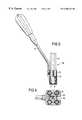
- FIG. 3is a transverse section taken substantially alone line A of FIG. 1 .
- FIG. 4is a view in section taken substantially along line B of FIG. 1 and showing a detail of embodiment of the object of the invention.
- FIG. 5is a partial elevational section of an instrument for positioning a plate according to the invention.
- FIG. 6is a plan view of the instrument illustrated in FIG. 5 .
- FIG. 7illustrates the use of a connection devices for assembling three vertebrae.
- FIG. 8is a view in perspective showing another embodiment of an intervertebral connection device according to the invention.
- FIG. 9is a partial sectional view showing a characteristic detail of the connection device according to FIG. 8 .
- FIG. 1 to 4illustrate a first embodiment of an osteosynthesis or intervertebral connection device 1 adapted to be mounted on the outer face of the cervical vertebrae.
- the connection device 1comprises an osteosynthesis or rigid connection plate 2 adapted to cover at least partially two consecutive or contiguous vertebrae (not shown).
- the connection plate 2comprises an anterior face 5 and an opposite or posterior face 6 intended to be applied against the outer face of the vertebrae, namely the anterior face in the example illustrated.
- the connection plate 2maybe mounted differently, for example laterally on the vertebrae.
- connection plate 2presents a small thickness, for example of the order of 1 mm, and is made of a rigid material, such as titanium or other metals, or polymer. As is shown more precisely in FIG. 2, the connection plate 2 preferably presents, in the sagittal plane S considered as the plane of the sheet according to FIG. 2, a curvature adapted to the profile of the contiguous vertebrae to be assembled. In the same sense, the connection plate 2 presents, in a cross section transverse with respect to the sagittal plane S (FIG. 3 ), a curvature concave along the posterior face 6 .
- the plate 2comprises at least one end, in the embodiment illustrated, two pairs of holes 8 each extending opposite one of the bones or the two vertebrae 3 and 4 .
- Each hole 8is intended to receive an anchoring screw 9 screwed in the corresponding vertebra by applying the posterior face 6 of the connection plate 2 against the outer face of the vertebrae.
- Each anchoring screw 9is conventionally provided with a widened head 11 intended to be housed inside a dish 8 I of the hole 8 , opening from the anterior face 5 of the plate 2 .
- each head 11 of an anchoring screwcomprises a hexagonal orifice 12 for screwing or unscrewing.
- the connection device 1also comprises an anti-extraction device 15 preventing extraction of the anchoring screws 9 .
- the anti-extraction device 15is constituted by at least one mobile flap 16 mounted on the anterior face 5 of the plate 2 via a guide device 17 for positioning the mobile flap 16 .
- the mobile flap 16is adapted in order, in a first position P 1 , shown in dot-and-ash lines in FIG. 1, to free the cross-section of passage of the holes 8 and, in a second position P 2 , as illustrated in FIG. 1, to obturate the holes 8 at least partially so as to constitute stops for the heads 11 of the screws.
- the mobile flap 16is of the rotating or turning type and is guided in a pivoting movement about an axis X extending substantially perpendicularly to the connection plate 2 .
- the mobile flap 16is equipped with a central ring 19 which is engaged in a bore 21 made on the connection plate 2 .
- the ring 19is crimped from the posterior face 6 of the plate 2 .
- the crimping effectedis of the tight type, i.e. a friction appears between the mobile flap 16 and the connection plate 2 .
- the mobile flap 16comprises arms 23 , in a number equal to the number of holes 8 , namely four in the example illustrated.
- the arms 23extend substantially in a common plane which, in the example illustrated, is substantially parallel to the connection plate 2 .
- the plane of extension of the mobile flap 16presents an incurved profile complementary of the incurved profile of the connection plate 2 .
- the arms 23 of the flap 16extend radially from the central ring 19 and are offset angularly with respect to one another in order, in the first position P 1 , to free the cross-section of passage of the holes 8 and, in the second position P 2 , to obturate the holes 8 at least partially.
- Each arm 23preferably presents a length or an extension adapted to come in position P 2 , at least to extend along a radius of the hole 8 . In this way, the arms 23 can constitute stops for the heads 11 of the screws 9 .
- the mobile flap 16is equipped with a member 25 for receiving a tool for control in displacement ensuring passage of the mobile flap 16 from the first position P 1 to the second position P 2 , and vice versa.
- the receiving member 25is constituted by a central orifice of prismatic shape made in the bore of the ring 19 .
- connection device 1is intended to be positioned with the aid of an instrument 30 comprising a handle 31 removably mounted on a guide block 32 designed to bear the plate 2 from its lower face with the aid, for example, of clipping devices.
- the guide block 32comprises a series of bores 33 made so as, in position of superposition with the osteosynthesis plate 2 , to be in registry with the holes 8 of the plate. In this way, the block 32 makes it possible to guide, with the aid of the bores 33 , diverse tools 34 ensuring positioning of the plate and shown schematically.
- the guide and block 32also comprises a window 35 for guiding. extending over the whole height of the block to open out on the lower and upper faces of the block. This window 35 is arranged to allow, in position of assembly or of superposition of the device 1 on the block 32 , access to the receiving member 25 and passage of the tool for controlling displacement of the mobile flap 16 .
- connection device 1According to the invention follows directly from the foregoing description.
- connection plate 2In order to be positioned on the vertebrae of a patient, the connection plate 2 is mounted, for example by clipping, on the guide block 32 .
- the mobile flap 16is placed so as to occupy its position P 1 freeing the cross-section of passage of the holes 8 .
- the conventional operations of positioning the anchoring screws on the vertebraemay thus be carried out.
- the mobile flap 16is intended to be controlled in rotation with the aid of an appropriate control tool which passes through the guide window 35 to engage in the receiving member 25 presented by the mobile flap 16 . Rotation of the control tool ensures passage of the mobile flap 16 from position P 1 to position P 2 in which the arms 23 are in position of superposition with the heads 11 of the screws.
- Each armconstitutes a stop for a screw head preventing avulsion or extraction thereof. In this way, there is no clearance between the screws 9 , the connection plate 2 and the body of the vertebrae.
- the anti-extraction device 15 according to the inventionis relatively simple and quick to deploy, while being safe both during and after they have been placed in position.
- the connection device 1comprises a stop element 40 for stopping the mobile flap 16 in the position of blocking P 2 of the screws 9 .
- the stop element 40comprises a device for limiting the pivoting of the mobile flap 16 .
- the plate 2comprises, as the stop element 40 , a lug or a stud placed on the path of at least one of the arms 23 to ensure abutment of an arm and, consequently, the placing of the arms in position of superposition with respect to the heads 11 of the screws.
- the stop stud or stop element 40thus serves as reference stop for positioning the mobile flap 16 in its screw-blocking position P 2 .
- the stop device 40is constituted not only by blocking means, of the obstacle type, but also by a the friction type blocking device constituted by the tight crimping of the mobile flap 16 on the connection plate 2 .
- the mobile flap 16is blocked, in position P 2 , in its two directions of rotation.
- the mobile flap 16is of the rotating type, but it is clear that the use of a sliding flap may be envisaged, or one moving in rectilinear manner from a control which is either rectilinear or pivoting, converted into a linear displacement.
- the mobile flap 16may be composed of one or more parts as a function of the dimensions of the connection plate 2 and of the arrangement of the holes 8 .
- FIG. 7illustrates another embodiment in which the connection device 2 comprises three pairs of holes 8 allowing the assembly of three contiguous vertebrae.
- each mobile flap 16presents solely two arms 23 offset angularly with respect to each other in order, in the first position P 1 , to free the cross-section of passage of the holes 8 and, in the second position P 2 , to bock the head 11 of the screws in order to prevent extraction thereof.
- the mobile flap 16may be adapted to block one sole screw head.
- the connection plate 2comprises only two holes for the passage of connection screws between two contiguous vertebrae.
- Such a plateis possible in particular when it is equipped with a cage intended to occupy the intervertebral space.
- FIGS. 8 and 9illustrate another variant embodiment in which stop device 40 for stopping the mobile flap 16 is arranged for blocking the flap in its two directions of rotation.
- the mobile flap 16is equipped on its inner face 16 a directed towards the anterior face 5 of the plate, with at least one and, for example, with four studs 42 in abutment on the anterior face 5 when the mobile flap 16 occupies its position P 1 of free access to the holes 8 .
- Each stud 42is intended to be engaged in a complementary housing 43 made from the anterior face 5 of the plate and located so that the stud 42 and the housing 43 cooperate when the mobile flap 16 occupies the position P 2 preventing extraction of the screws.
- the mobile flap 16is therefore blocked in its two directions of rotation.
Landscapes
- Health & Medical Sciences (AREA)
- Orthopedic Medicine & Surgery (AREA)
- Surgery (AREA)
- Life Sciences & Earth Sciences (AREA)
- Heart & Thoracic Surgery (AREA)
- Veterinary Medicine (AREA)
- Engineering & Computer Science (AREA)
- Biomedical Technology (AREA)
- Nuclear Medicine, Radiotherapy & Molecular Imaging (AREA)
- Medical Informatics (AREA)
- Molecular Biology (AREA)
- Animal Behavior & Ethology (AREA)
- General Health & Medical Sciences (AREA)
- Public Health (AREA)
- Neurology (AREA)
- Dentistry (AREA)
- Oral & Maxillofacial Surgery (AREA)
- Prostheses (AREA)
Abstract
Description
Claims (22)
Applications Claiming Priority (2)
| Application Number | Priority Date | Filing Date | Title |
|---|---|---|---|
| FR9813224AFR2784570B1 (en) | 1998-10-19 | 1998-10-19 | INTERVERTEBRAL CONNECTION DEVICE HAVING ANTI-EXTRACTION MEANS FOR ANCHORAGE SCREWS |
| FR9813224 | 1998-10-19 |
Publications (1)
| Publication Number | Publication Date |
|---|---|
| US6306139B1true US6306139B1 (en) | 2001-10-23 |
Family
ID=9531846
Family Applications (1)
| Application Number | Title | Priority Date | Filing Date |
|---|---|---|---|
| US09/271,287Expired - LifetimeUS6306139B1 (en) | 1998-10-19 | 1999-03-17 | Intervertebral connection device with an anti-extraction device to prevent extraction of anchoring screws |
Country Status (2)
| Country | Link |
|---|---|
| US (1) | US6306139B1 (en) |
| FR (1) | FR2784570B1 (en) |
Cited By (138)
| Publication number | Priority date | Publication date | Assignee | Title |
|---|---|---|---|---|
| US6503250B2 (en)* | 2000-11-28 | 2003-01-07 | Kamaljit S. Paul | Bone support assembly |
| US20030135213A1 (en)* | 2001-04-06 | 2003-07-17 | Lehuec Jean-Charles | Anterior planting system and method |
| WO2004012608A1 (en)* | 2002-08-02 | 2004-02-12 | Depuy Acromed, Inc. | Screw placement guide |
| US20040030338A1 (en)* | 2001-12-14 | 2004-02-12 | Paul Kamaljit S. | Spinal plate assembly |
| US20040034354A1 (en)* | 2002-07-24 | 2004-02-19 | Paul Kamaljit S. | Bone support assembly |
| US20040039387A1 (en)* | 2002-08-22 | 2004-02-26 | Larry Gause | System for stabilizing a portion of the spine |
| US20040097940A1 (en)* | 2001-12-14 | 2004-05-20 | Paul Kamaljit S. | Bone treatment plate assembly |
| US20040133205A1 (en)* | 2002-06-24 | 2004-07-08 | Jeffrey Thramann | Cervical plate |
| US20040204716A1 (en)* | 2003-04-09 | 2004-10-14 | Jonathan Fanger | Drill guide with alignment feature |
| US20040210232A1 (en)* | 2003-04-09 | 2004-10-21 | Tushar Patel | Guide device and plate inserter |
| US20040210217A1 (en)* | 2003-04-21 | 2004-10-21 | Baynham Bret O'neil | Bone fixation plate |
| US20040210221A1 (en)* | 2000-10-25 | 2004-10-21 | Jeffrey Kozak | Anterior lumbar plate and method |
| US20040215195A1 (en)* | 2003-04-25 | 2004-10-28 | Sdgi Holdings, Inc. | Non-metallic orthopedic plate |
| US20050004574A1 (en)* | 2003-06-11 | 2005-01-06 | Helmut Muckter | Osteosynthesis plate or comparable implant plus ball socket |
| US20050010227A1 (en)* | 2000-11-28 | 2005-01-13 | Paul Kamaljit S. | Bone support plate assembly |
| US20050027296A1 (en)* | 2002-06-24 | 2005-02-03 | Jeffrey Thramann | Cervical plate with backout protection |
| US20050071006A1 (en)* | 2003-09-30 | 2005-03-31 | Kirschman David Louis | Spinal fusion system and method for fusing spinal bones |
| EP1520545A1 (en)* | 2003-10-01 | 2005-04-06 | SDGI Holdings, Inc. | Spinal device locking mechanism |
| US20050101960A1 (en)* | 2001-04-03 | 2005-05-12 | Vincent Fiere | Stabilised interbody fusion system for vertebrae |
| US20050187553A1 (en)* | 2001-08-24 | 2005-08-25 | Grabowski John J. | Bone fixation device |
| US20050234455A1 (en)* | 2004-04-19 | 2005-10-20 | Lawrence Binder | Bone fixation plate |
| US20060074420A1 (en)* | 2002-07-16 | 2006-04-06 | Lehuec Jean-Charles | Plating system for stabilizing a bony segment |
| US7025769B1 (en)* | 2002-06-04 | 2006-04-11 | Nuvasive, Inc. | Surgical fixation system and related methods |
| US20060106399A1 (en)* | 2004-11-18 | 2006-05-18 | Taras John S | Drill guide tissue protector |
| US20060122602A1 (en)* | 2004-12-08 | 2006-06-08 | Depuy Spine, Inc. | Hybrid spinal plates |
| US20060161158A1 (en)* | 2004-12-14 | 2006-07-20 | Orbay Jorge L | Bone fracture fixation plate shaping system |
| US7081119B2 (en) | 2003-08-01 | 2006-07-25 | Hfsc Company | Drill guide assembly for a bone fixation device |
| US20060200146A1 (en)* | 2005-01-06 | 2006-09-07 | Doubler Robert L | Spinal plate with screw locks and cam locks |
| US20060206208A1 (en)* | 1999-05-05 | 2006-09-14 | Sdgi Holdings, Inc. | Push-in interbody spinal fusion implant with multi-lock for locking opposed screws and method for use thereof |
| US20060229618A1 (en)* | 2005-03-16 | 2006-10-12 | Dube Michael A | Anterior lumbar lag plate |
| US20060229620A1 (en)* | 2005-03-03 | 2006-10-12 | Accin Corporation | Method and apparatus for providing a retainer for a bone stabilization device |
| US20060282075A1 (en)* | 2005-06-10 | 2006-12-14 | Depuy Spine, Inc. | Posterior dynamic stabilization x-device |
| US20070055252A1 (en)* | 2005-03-17 | 2007-03-08 | Jason Blain | Flanged interbody fusion device with oblong fastener apertures |
| US20070233112A1 (en)* | 2006-03-20 | 2007-10-04 | Orbay Jorge L | Method of Bone Plate Shaping |
| US20070233111A1 (en)* | 2006-03-20 | 2007-10-04 | Orbay Jorge L | Bone Plate Shaping System |
| US7306605B2 (en) | 2003-10-02 | 2007-12-11 | Zimmer Spine, Inc. | Anterior cervical plate |
| US7357804B2 (en) | 2003-08-13 | 2008-04-15 | Synthes (U.S.A.) | Quick-release drill-guide assembly for bone-plate |
| US20080108998A1 (en)* | 2006-11-02 | 2008-05-08 | Warsaw Orthopedic Inc. | Uni-directional ratcheting bone plate assembly |
| US7416553B2 (en) | 2003-04-09 | 2008-08-26 | Depuy Acromed, Inc. | Drill guide and plate inserter |
| US7488327B2 (en) | 2004-04-12 | 2009-02-10 | Synthes (U.S.A.) | Free hand drill guide |
| US20090105831A1 (en)* | 2007-10-19 | 2009-04-23 | Jones Robert J | Locking mechanisms and associated methods |
| US20090171396A1 (en)* | 2003-04-21 | 2009-07-02 | Baynham Matthew G | Bone fixation plate |
| US20090210064A1 (en)* | 2003-02-06 | 2009-08-20 | Beat Lechmann | Intervertebral implant |
| USD603507S1 (en) | 2008-07-03 | 2009-11-03 | Theken Spine, Llc | Cervical plate |
| USD603510S1 (en) | 2008-07-03 | 2009-11-03 | Theken Spine, Llc | Cervical plate |
| USD603505S1 (en) | 2008-07-03 | 2009-11-03 | Theken Spine, Llc | Cervical plate |
| USD603504S1 (en) | 2008-07-03 | 2009-11-03 | Theken Spine, Llc | Cervical plate |
| USD603503S1 (en) | 2008-07-03 | 2009-11-03 | Theken Spine, Llc | Cervical plate |
| USD603511S1 (en) | 2008-07-03 | 2009-11-03 | Theken Spine, Llc | Cervical plate |
| USD603509S1 (en) | 2008-07-03 | 2009-11-03 | Theken Spine, Llc | Cervical plate |
| USD603508S1 (en) | 2008-07-03 | 2009-11-03 | Theken Spine, Llc | Cervical plate |
| USD603506S1 (en) | 2008-07-03 | 2009-11-03 | Theken Spine, Llc | Cervical plate |
| USD603962S1 (en) | 2008-07-03 | 2009-11-10 | Theken Spine, Llc | Cervical plate |
| USD603963S1 (en) | 2008-07-03 | 2009-11-10 | Theken Spine, Llc | Cervical plate |
| USD603964S1 (en) | 2008-07-03 | 2009-11-10 | Theken Spine, Llc | Cervical plate |
| USD603961S1 (en) | 2008-07-03 | 2009-11-10 | Theken Spine, Llc | Cervical plate |
| US7641701B2 (en) | 2003-09-30 | 2010-01-05 | X-Spine Systems, Inc. | Spinal fusion system and method for fusing spinal bones |
| US20100069968A1 (en)* | 1998-04-30 | 2010-03-18 | Sofamor S.N.C. | Anterior implant for the spine |
| US7682392B2 (en) | 2002-10-30 | 2010-03-23 | Depuy Spine, Inc. | Regenerative implants for stabilizing the spine and devices for attachment of said implants |
| US20100100131A1 (en)* | 2008-10-21 | 2010-04-22 | K2M, Inc. | Spinal buttress plate |
| US7731721B2 (en) | 2003-07-16 | 2010-06-08 | Synthes Usa, Llc | Plating system with multiple function drill guide |
| US7736380B2 (en) | 2004-12-21 | 2010-06-15 | Rhausler, Inc. | Cervical plate system |
| US7740649B2 (en) | 2004-02-26 | 2010-06-22 | Pioneer Surgical Technology, Inc. | Bone plate system and methods |
| US7766911B1 (en) | 2002-07-05 | 2010-08-03 | Theken Spine, Llc | Fixed and variable locking fixation assembly |
| US7776047B2 (en) | 2003-04-09 | 2010-08-17 | Depuy Spine, Inc. | Guide for spinal tools, implants, and devices |
| US20100217393A1 (en)* | 2009-02-20 | 2010-08-26 | Theofilos Charles S | Interbody fusion system with intervertebral implant retention assembly |
| US20100234897A1 (en)* | 2009-03-13 | 2010-09-16 | Lanx, Inc. | Spinal plate assemblies with backout protection cap and methods |
| US20100256686A1 (en)* | 2009-04-06 | 2010-10-07 | Lanx, Inc. | Bone plate assemblies with backout protection and visual indicator |
| US7887595B1 (en) | 2005-12-05 | 2011-02-15 | Nuvasive, Inc. | Methods and apparatus for spinal fusion |
| US7909848B2 (en) | 2003-06-27 | 2011-03-22 | Depuy Spine, Inc. | Tissue retractor and guide device |
| US7909829B2 (en) | 2003-06-27 | 2011-03-22 | Depuy Spine, Inc. | Tissue retractor and drill guide |
| US7963982B2 (en) | 2007-07-16 | 2011-06-21 | X-Spine Systems, Inc. | Implant plate screw locking system and screw having a locking member |
| US8062367B2 (en) | 2003-09-30 | 2011-11-22 | X-Spine Systems, Inc. | Screw locking mechanism and method |
| US8114162B1 (en) | 2006-08-09 | 2012-02-14 | Nuvasive, Inc. | Spinal fusion implant and related methods |
| US8172886B2 (en) | 2004-12-14 | 2012-05-08 | Depuy Products, Inc. | Bone plate with pre-assembled drill guide tips |
| US8172885B2 (en) | 2003-02-05 | 2012-05-08 | Pioneer Surgical Technology, Inc. | Bone plate system |
| US8236034B2 (en) | 2004-04-19 | 2012-08-07 | Globus Medical, Inc. | Bone fixation plate |
| US8328856B1 (en) | 2008-10-14 | 2012-12-11 | Nuvasive, Inc. | Surgical fixation system and related methods |
| US20120330426A1 (en)* | 2010-04-12 | 2012-12-27 | Mclaughlin Colm | Expandable Vertebral Implant |
| US20130012993A1 (en)* | 2008-08-06 | 2013-01-10 | The University Of Toledo | Cervical Plate Assembly |
| US8361126B2 (en) | 2007-07-03 | 2013-01-29 | Pioneer Surgical Technology, Inc. | Bone plate system |
| US8372152B2 (en) | 2003-09-30 | 2013-02-12 | X-Spine Systems, Inc. | Spinal fusion system utilizing an implant plate having at least one integral lock and ratchet lock |
| US8419777B2 (en) | 2009-07-24 | 2013-04-16 | Spinal Usa, Inc. | Bone plate screw-blocking systems and methods |
| US8454667B2 (en) | 2010-12-16 | 2013-06-04 | Warsaw Orhtopedic, Inc. | Retaining mechanism |
| US8535354B2 (en) | 2009-07-24 | 2013-09-17 | Spinal Usa, Inc. | Bone plate system and methods of using the same |
| US20130345814A1 (en)* | 2011-11-17 | 2013-12-26 | Lanx, Inc. | Modular Anchor Bone Fusion Cage |
| US8623019B2 (en) | 2007-07-03 | 2014-01-07 | Pioneer Surgical Technology, Inc. | Bone plate system |
| US20140012384A1 (en)* | 2011-07-12 | 2014-01-09 | Spinesmith Partners, L.P. | Interbody fusion device and associated methods |
| US8647369B2 (en) | 2010-05-19 | 2014-02-11 | Josef E. Gorek | Minimal profile anterior bracket for spinal fixation |
| US8652182B1 (en)* | 2008-10-01 | 2014-02-18 | Spinal U.S.A. | Bone plate with retainer and stop for screw lock |
| US8740983B1 (en) | 2009-11-11 | 2014-06-03 | Nuvasive, Inc. | Spinal fusion implants and related methods |
| US8753396B1 (en) | 2010-09-13 | 2014-06-17 | Theken Spine, Llc | Intervertebral implant having back-out prevention feature |
| USD708747S1 (en) | 2006-09-25 | 2014-07-08 | Nuvasive, Inc. | Spinal fusion implant |
| US8821553B2 (en) | 2003-09-30 | 2014-09-02 | X-Spine Systems, Inc. | Spinal fusion system utilizing an implant plate having at least one integral lock |
| US20140277182A1 (en)* | 2013-03-12 | 2014-09-18 | Warsaw Orthopedic, Inc. | Spinal implant system and method |
| US8840668B1 (en) | 2009-11-11 | 2014-09-23 | Nuvasive, Inc. | Spinal implants, instruments and related methods |
| US8858603B1 (en) | 2010-06-09 | 2014-10-14 | Choice Spine, L.P. | Cervical plate with screw retention clip |
| US8900277B2 (en) | 2004-02-26 | 2014-12-02 | Pioneer Surgical Technology, Inc. | Bone plate system |
| US8932335B2 (en) | 2012-08-31 | 2015-01-13 | Warsaw Orthopedic, Inc. | Retaining mechanism |
| US8940030B1 (en) | 2011-01-28 | 2015-01-27 | Nuvasive, Inc. | Spinal fixation system and related methods |
| US9005295B2 (en) | 2007-11-16 | 2015-04-14 | DePuy Synthes Products, LLC | Low profile intervertebral implant |
| US9011540B1 (en)* | 2005-03-24 | 2015-04-21 | Igip, Llc | Overlay or implant and method for improving stability of the implant |
| US9039775B2 (en) | 2003-03-31 | 2015-05-26 | DePuy Synthes Products, Inc. | Spinal fixation plates |
| US9078706B2 (en) | 2003-09-30 | 2015-07-14 | X-Spine Systems, Inc. | Intervertebral fusion device utilizing multiple mobile uniaxial and bidirectional screw interface plates |
| US9186189B2 (en) | 2000-06-26 | 2015-11-17 | Stryker Spine | Bone screw retaining system |
| US9192419B2 (en) | 2008-11-07 | 2015-11-24 | DePuy Synthes Products, Inc. | Zero-profile interbody spacer and coupled plate assembly |
| USD745159S1 (en) | 2013-10-10 | 2015-12-08 | Nuvasive, Inc. | Intervertebral implant |
| US9220604B2 (en) | 2010-12-21 | 2015-12-29 | DePuy Synthes Products, Inc. | Intervertebral implants, systems, and methods of use |
| US9220547B2 (en) | 2009-03-27 | 2015-12-29 | Spinal Elements, Inc. | Flanged interbody fusion device |
| US9241809B2 (en) | 2010-12-21 | 2016-01-26 | DePuy Synthes Products, Inc. | Intervertebral implants, systems, and methods of use |
| US20160106553A1 (en)* | 2013-10-07 | 2016-04-21 | Warsaw Orthopedic, Inc. | Spinal implant system and method |
| US9408646B2 (en) | 2003-09-03 | 2016-08-09 | DePuy Synthes Products, Inc. | Bone plate with captive clips |
| US9414870B2 (en) | 2003-09-03 | 2016-08-16 | DePuy Synthes Products, Inc. | Translatable carriage fixation system |
| US9510880B2 (en) | 2013-08-13 | 2016-12-06 | Zimmer, Inc. | Polyaxial locking mechanism |
| US20170020683A1 (en)* | 2003-04-21 | 2017-01-26 | Rsb Spine Llc | Bone plate stabilization system and method for its use |
| US9572681B2 (en) | 2002-02-19 | 2017-02-21 | DePuy Synthes Products, Inc. | Intervertebral implant |
| US9867718B2 (en) | 2014-10-22 | 2018-01-16 | DePuy Synthes Products, Inc. | Intervertebral implants, systems, and methods of use |
| US9987052B2 (en) | 2015-02-24 | 2018-06-05 | X-Spine Systems, Inc. | Modular interspinous fixation system with threaded component |
| US10172655B2 (en) | 2013-10-01 | 2019-01-08 | Degen Medical, Inc. | Osteosynthesis system, assemblies and components |
| US20190209215A1 (en)* | 2018-01-05 | 2019-07-11 | Atlas Spine, Inc. | Locking cervical plate |
| USD857894S1 (en) | 2007-08-20 | 2019-08-27 | Nuvasive, Inc. | Surgical fixation system |
| USD858769S1 (en) | 2014-11-20 | 2019-09-03 | Nuvasive, Inc. | Intervertebral implant |
| US10405900B2 (en)* | 2017-08-08 | 2019-09-10 | Solco Biomedical Co., Ltd. | Apparatus for fixing cervical spine |
| US10512548B2 (en) | 2006-02-27 | 2019-12-24 | DePuy Synthes Products, Inc. | Intervertebral implant with fixation geometry |
| US10758361B2 (en) | 2015-01-27 | 2020-09-01 | Spinal Elements, Inc. | Facet joint implant |
| US11000321B2 (en) | 2017-05-25 | 2021-05-11 | Altus Partners Llc | Secondary screw blocking mechanism |
| USD925740S1 (en) | 2019-11-26 | 2021-07-20 | GetSet Surgical SA | Spinal fusion cage |
| US11123117B1 (en) | 2011-11-01 | 2021-09-21 | Nuvasive, Inc. | Surgical fixation system and related methods |
| US11173042B2 (en) | 2019-11-26 | 2021-11-16 | GetSet Surgical SA | Spinal surgery devices, systems, and methods |
| US11273057B2 (en) | 2019-11-26 | 2022-03-15 | GetSet Surgical SA | Spinal surgery instruments, systems, and methods |
| US11278426B2 (en) | 2019-11-26 | 2022-03-22 | GetSet Surgical SA | Spinal surgery assemblies, systems, and methods |
| US11298244B2 (en) | 2019-01-31 | 2022-04-12 | K2M, Inc. | Interbody implants and instrumentation |
| US11382769B2 (en) | 2018-09-20 | 2022-07-12 | Spinal Elements, Inc. | Spinal implant device |
| US11534307B2 (en) | 2019-09-16 | 2022-12-27 | K2M, Inc. | 3D printed cervical standalone implant |
| US11877779B2 (en) | 2020-03-26 | 2024-01-23 | Xtant Medical Holdings, Inc. | Bone plate system |
| US11911284B2 (en) | 2020-11-19 | 2024-02-27 | Spinal Elements, Inc. | Curved expandable interbody devices and deployment tools |
| WO2024096731A1 (en)* | 2022-11-03 | 2024-05-10 | Panoni's B.V. | A device for operating on a pedicle within a patient |
| US12279969B2 (en) | 2020-12-17 | 2025-04-22 | Spinal Elements, Inc. | Spinal implant device |
Families Citing this family (1)
| Publication number | Priority date | Publication date | Assignee | Title |
|---|---|---|---|---|
| EP2594214A1 (en)* | 2003-08-01 | 2013-05-22 | Lanx LLC | Cervical plate |
Citations (5)
| Publication number | Priority date | Publication date | Assignee | Title |
|---|---|---|---|---|
| US4794918A (en)* | 1985-05-06 | 1989-01-03 | Dietmar Wolter | Bone plate arrangement |
| EP0599640A1 (en) | 1992-11-25 | 1994-06-01 | CODMAN & SHURTLEFF INC. | Osteosynthesis plate system |
| FR2740321A1 (en) | 1995-10-27 | 1997-04-30 | Fuentes Jean Marc | Osteosynthesis insert for cervical vertebrae |
| WO1998034553A1 (en) | 1997-02-11 | 1998-08-13 | Michelson Gary K | Anterior cervical plating system, instrumentation, and method of installation |
| US5951558A (en)* | 1998-04-22 | 1999-09-14 | Fiz; Daniel | Bone fixation device |
- 1998
- 1998-10-19FRFR9813224Apatent/FR2784570B1/ennot_activeExpired - Fee Related
- 1999
- 1999-03-17USUS09/271,287patent/US6306139B1/ennot_activeExpired - Lifetime
Patent Citations (5)
| Publication number | Priority date | Publication date | Assignee | Title |
|---|---|---|---|---|
| US4794918A (en)* | 1985-05-06 | 1989-01-03 | Dietmar Wolter | Bone plate arrangement |
| EP0599640A1 (en) | 1992-11-25 | 1994-06-01 | CODMAN & SHURTLEFF INC. | Osteosynthesis plate system |
| FR2740321A1 (en) | 1995-10-27 | 1997-04-30 | Fuentes Jean Marc | Osteosynthesis insert for cervical vertebrae |
| WO1998034553A1 (en) | 1997-02-11 | 1998-08-13 | Michelson Gary K | Anterior cervical plating system, instrumentation, and method of installation |
| US5951558A (en)* | 1998-04-22 | 1999-09-14 | Fiz; Daniel | Bone fixation device |
Cited By (310)
| Publication number | Priority date | Publication date | Assignee | Title |
|---|---|---|---|---|
| US20100069968A1 (en)* | 1998-04-30 | 2010-03-18 | Sofamor S.N.C. | Anterior implant for the spine |
| US8016864B2 (en)* | 1998-04-30 | 2011-09-13 | Warsaw Orthopedic, Inc. | Anterior implant for the spine |
| US8353959B2 (en) | 1999-05-05 | 2013-01-15 | Warsaw Orthopedic, Inc. | Push-in interbody spinal fusion implants for use with self-locking screws |
| US8403986B2 (en) | 1999-05-05 | 2013-03-26 | Warsaw Orthopedic, Inc. | Push-in interbody spinal fusion implant with multi-lock for locking opposed screws and method for use thereof |
| US20060206208A1 (en)* | 1999-05-05 | 2006-09-14 | Sdgi Holdings, Inc. | Push-in interbody spinal fusion implant with multi-lock for locking opposed screws and method for use thereof |
| US9186189B2 (en) | 2000-06-26 | 2015-11-17 | Stryker Spine | Bone screw retaining system |
| US20040210221A1 (en)* | 2000-10-25 | 2004-10-21 | Jeffrey Kozak | Anterior lumbar plate and method |
| US8016863B2 (en) | 2000-10-25 | 2011-09-13 | Warsaw Orthopedic, Inc. | Anterior lumbar plate and method |
| US8617224B2 (en) | 2000-10-25 | 2013-12-31 | Warsaw Orthopedic, Inc. | Anterior lumbar plate and method |
| US20050010227A1 (en)* | 2000-11-28 | 2005-01-13 | Paul Kamaljit S. | Bone support plate assembly |
| US7727265B2 (en) | 2000-11-28 | 2010-06-01 | Paul Kamaljit S | Bone support plate assembly |
| US20050216011A1 (en)* | 2000-11-28 | 2005-09-29 | Paul Kamaljit S | Bone support plate assembly |
| US20030149434A1 (en)* | 2000-11-28 | 2003-08-07 | Paul Kamaljit S. | Bone support assembly |
| US6503250B2 (en)* | 2000-11-28 | 2003-01-07 | Kamaljit S. Paul | Bone support assembly |
| US7172627B2 (en)* | 2001-04-03 | 2007-02-06 | Scient'x | Stabilized interbody fusion system for vertebrae |
| US20050101960A1 (en)* | 2001-04-03 | 2005-05-12 | Vincent Fiere | Stabilised interbody fusion system for vertebrae |
| US7758616B2 (en)* | 2001-04-06 | 2010-07-20 | Warsaw Orthopedic, Inc. | Anterior plating system and method |
| US20100228294A1 (en)* | 2001-04-06 | 2010-09-09 | Warsaw Othropedic.Inc. | Anterior plating system and method |
| US6793658B2 (en) | 2001-04-06 | 2004-09-21 | Society De Fabrication De Material Orthopedique, S.A. | Anterior plating system and method |
| US6884242B2 (en) | 2001-04-06 | 2005-04-26 | Society De Fabrication De Materiel Orthopedique, S.A. | Anterior plating system and method |
| US8388662B2 (en) | 2001-04-06 | 2013-03-05 | Warsaw Orthopedic, Inc | Anterior plating system and method |
| US20050027293A1 (en)* | 2001-04-06 | 2005-02-03 | Lehuec Jean-Charles | Anterior plating system and method |
| US20030135213A1 (en)* | 2001-04-06 | 2003-07-17 | Lehuec Jean-Charles | Anterior planting system and method |
| US7833226B2 (en)* | 2001-08-24 | 2010-11-16 | Zimmer Spine, Inc. | Bone fixation device |
| US20050187553A1 (en)* | 2001-08-24 | 2005-08-25 | Grabowski John J. | Bone fixation device |
| US20040030338A1 (en)* | 2001-12-14 | 2004-02-12 | Paul Kamaljit S. | Spinal plate assembly |
| US6755833B1 (en) | 2001-12-14 | 2004-06-29 | Kamaljit S. Paul | Bone support assembly |
| US20040153069A1 (en)* | 2001-12-14 | 2004-08-05 | Paul Kamaljit S. | Spinal plate assembly |
| US7255699B2 (en) | 2001-12-14 | 2007-08-14 | Paul Kamaljit S | Spinal plate assembly |
| US7204837B2 (en) | 2001-12-14 | 2007-04-17 | Paul Kamaljit S | Spinal plate assembly |
| US7008426B2 (en) | 2001-12-14 | 2006-03-07 | Paul Kamaljit S | Bone treatment plate assembly |
| US8221476B2 (en) | 2001-12-14 | 2012-07-17 | Paul Kamaljit S | Spinal plate assembly |
| US8236033B2 (en) | 2001-12-14 | 2012-08-07 | Paul Kamaljit S | Spinal plate assembly |
| US20040097940A1 (en)* | 2001-12-14 | 2004-05-20 | Paul Kamaljit S. | Bone treatment plate assembly |
| US8128668B2 (en) | 2001-12-14 | 2012-03-06 | Paul Kamaljit S | Bone treatment plate assembly |
| US20060142768A1 (en)* | 2001-12-14 | 2006-06-29 | Paul Kamaljit S | Bone treatment plate assembly |
| US9572681B2 (en) | 2002-02-19 | 2017-02-21 | DePuy Synthes Products, Inc. | Intervertebral implant |
| US10492922B2 (en) | 2002-02-19 | 2019-12-03 | DePuy Synthes Products, Inc. | Intervertebral implant |
| US7025769B1 (en)* | 2002-06-04 | 2006-04-11 | Nuvasive, Inc. | Surgical fixation system and related methods |
| US7175623B2 (en) | 2002-06-24 | 2007-02-13 | Lanx, Llc | Cervical plate with backout protection |
| US7077843B2 (en) | 2002-06-24 | 2006-07-18 | Lanx, Llc | Cervical plate |
| US20050027296A1 (en)* | 2002-06-24 | 2005-02-03 | Jeffrey Thramann | Cervical plate with backout protection |
| US20070233120A1 (en)* | 2002-06-24 | 2007-10-04 | Lanx, Llc | Cervical plate |
| US8652181B2 (en) | 2002-06-24 | 2014-02-18 | Lanx, Inc. | Cervical plate |
| US8778001B2 (en)* | 2002-06-24 | 2014-07-15 | Lanx, Inc. | Cervical plate |
| US20040133205A1 (en)* | 2002-06-24 | 2004-07-08 | Jeffrey Thramann | Cervical plate |
| US20070016206A1 (en)* | 2002-06-24 | 2007-01-18 | Lanx, Llc | Cervical plate |
| US7785327B1 (en) | 2002-07-05 | 2010-08-31 | Theken Spine, Llc | Fixed and variable locking fixation assembly |
| US7766911B1 (en) | 2002-07-05 | 2010-08-03 | Theken Spine, Llc | Fixed and variable locking fixation assembly |
| US7780666B1 (en) | 2002-07-05 | 2010-08-24 | Theken Spine, Llc | Fixed and variable locking fixation assembly |
| US8070784B2 (en)* | 2002-07-16 | 2011-12-06 | Warsaw Orthopedic, Inc. | Plating system for stabilizing a bony segment |
| US20060074420A1 (en)* | 2002-07-16 | 2006-04-06 | Lehuec Jean-Charles | Plating system for stabilizing a bony segment |
| US7070599B2 (en) | 2002-07-24 | 2006-07-04 | Paul Kamaljit S | Bone support assembly |
| US20040034354A1 (en)* | 2002-07-24 | 2004-02-19 | Paul Kamaljit S. | Bone support assembly |
| US20040092952A1 (en)* | 2002-08-02 | 2004-05-13 | Peter Newton | Screw placement guide |
| WO2004012608A1 (en)* | 2002-08-02 | 2004-02-12 | Depuy Acromed, Inc. | Screw placement guide |
| US20080071285A1 (en)* | 2002-08-02 | 2008-03-20 | Depuy Spine, Inc. | Screw placement guide |
| US7981117B2 (en) | 2002-08-02 | 2011-07-19 | Depuy Spine, Inc. | Screw placement guide |
| US7862597B2 (en)* | 2002-08-22 | 2011-01-04 | Warsaw Orthopedic, Inc. | System for stabilizing a portion of the spine |
| US20040039387A1 (en)* | 2002-08-22 | 2004-02-26 | Larry Gause | System for stabilizing a portion of the spine |
| US9180020B2 (en) | 2002-08-22 | 2015-11-10 | Warsaw Orthopedic, Inc. | System for stabilizing a portion of the spine |
| US7682392B2 (en) | 2002-10-30 | 2010-03-23 | Depuy Spine, Inc. | Regenerative implants for stabilizing the spine and devices for attachment of said implants |
| US8172885B2 (en) | 2003-02-05 | 2012-05-08 | Pioneer Surgical Technology, Inc. | Bone plate system |
| US7862616B2 (en)* | 2003-02-06 | 2011-01-04 | Synthes Usa, Llc | Intervertebral implant |
| US8715354B2 (en) | 2003-02-06 | 2014-05-06 | DePuy Synthes Products, LLC | Intervertebral implant |
| US10660765B2 (en) | 2003-02-06 | 2020-05-26 | DePuy Synthes Products, Inc. | Intervertebral implant |
| US10064740B2 (en) | 2003-02-06 | 2018-09-04 | DePuy Synthes Products, LLC | Intervertebral implant |
| US9463097B2 (en) | 2003-02-06 | 2016-10-11 | DePuy Synthes Products, Inc. | Intervertebral implant |
| US8764831B2 (en) | 2003-02-06 | 2014-07-01 | DePuy Synthes Products, LLC | Intervertebral implant |
| US20090210064A1 (en)* | 2003-02-06 | 2009-08-20 | Beat Lechmann | Intervertebral implant |
| US8709085B2 (en) | 2003-02-06 | 2014-04-29 | DePuy Synthes Products, LLC | Intervertebral implant |
| US9039775B2 (en) | 2003-03-31 | 2015-05-26 | DePuy Synthes Products, Inc. | Spinal fixation plates |
| US9320549B2 (en) | 2003-03-31 | 2016-04-26 | DePuy Synthes Products, Inc. | Spinal fixation plates |
| US7776047B2 (en) | 2003-04-09 | 2010-08-17 | Depuy Spine, Inc. | Guide for spinal tools, implants, and devices |
| US20040210232A1 (en)* | 2003-04-09 | 2004-10-21 | Tushar Patel | Guide device and plate inserter |
| US7416553B2 (en) | 2003-04-09 | 2008-08-26 | Depuy Acromed, Inc. | Drill guide and plate inserter |
| US7935123B2 (en)* | 2003-04-09 | 2011-05-03 | Depuy Acromed, Inc. | Drill guide with alignment feature |
| US20040204716A1 (en)* | 2003-04-09 | 2004-10-14 | Jonathan Fanger | Drill guide with alignment feature |
| US8394107B2 (en) | 2003-04-09 | 2013-03-12 | Depuy Spine, Inc. | Guide for spinal tools, implants, and devices |
| US8348982B2 (en) | 2003-04-21 | 2013-01-08 | Atlas Spine, Inc. | Bone fixation plate |
| US7481829B2 (en) | 2003-04-21 | 2009-01-27 | Atlas Spine, Inc. | Bone fixation plate |
| US20090171396A1 (en)* | 2003-04-21 | 2009-07-02 | Baynham Matthew G | Bone fixation plate |
| US20170128230A1 (en)* | 2003-04-21 | 2017-05-11 | Rsb Spine Llc | Bone plate stabilization system and method for its use |
| US11026802B2 (en) | 2003-04-21 | 2021-06-08 | Rsb Spine Llc | Bone plate stabilization system and method for its use |
| US9713537B2 (en)* | 2003-04-21 | 2017-07-25 | Rsb Spine Llc | Bone plate stabilization system and method for its use |
| US20040210217A1 (en)* | 2003-04-21 | 2004-10-21 | Baynham Bret O'neil | Bone fixation plate |
| US20170020683A1 (en)* | 2003-04-21 | 2017-01-26 | Rsb Spine Llc | Bone plate stabilization system and method for its use |
| US20040215195A1 (en)* | 2003-04-25 | 2004-10-28 | Sdgi Holdings, Inc. | Non-metallic orthopedic plate |
| WO2004096068A1 (en)* | 2003-04-25 | 2004-11-11 | Sdgi Holdings Inc. | Non-metallic orthopedic plate |
| AU2004233785B2 (en)* | 2003-04-25 | 2010-05-27 | Warsaw Orthopedic, Inc. | Non-metallic orthopedic plate |
| US7169150B2 (en) | 2003-04-25 | 2007-01-30 | Warsaw Orthopedic, Inc. | Non-metallic orthopedic plate |
| US7276070B2 (en)* | 2003-06-11 | 2007-10-02 | Mueckter Helmut | Osteosynthesis plate or comparable implant plus ball socket |
| US20050004574A1 (en)* | 2003-06-11 | 2005-01-06 | Helmut Muckter | Osteosynthesis plate or comparable implant plus ball socket |
| US7909829B2 (en) | 2003-06-27 | 2011-03-22 | Depuy Spine, Inc. | Tissue retractor and drill guide |
| US7909848B2 (en) | 2003-06-27 | 2011-03-22 | Depuy Spine, Inc. | Tissue retractor and guide device |
| US7731721B2 (en) | 2003-07-16 | 2010-06-08 | Synthes Usa, Llc | Plating system with multiple function drill guide |
| US7081119B2 (en) | 2003-08-01 | 2006-07-25 | Hfsc Company | Drill guide assembly for a bone fixation device |
| US7357804B2 (en) | 2003-08-13 | 2008-04-15 | Synthes (U.S.A.) | Quick-release drill-guide assembly for bone-plate |
| US9408646B2 (en) | 2003-09-03 | 2016-08-09 | DePuy Synthes Products, Inc. | Bone plate with captive clips |
| US9414870B2 (en) | 2003-09-03 | 2016-08-16 | DePuy Synthes Products, Inc. | Translatable carriage fixation system |
| US10368927B2 (en) | 2003-09-03 | 2019-08-06 | DePuy Synthes Products, Inc. | Bone plate with captive clips |
| US8821553B2 (en) | 2003-09-30 | 2014-09-02 | X-Spine Systems, Inc. | Spinal fusion system utilizing an implant plate having at least one integral lock |
| US9078706B2 (en) | 2003-09-30 | 2015-07-14 | X-Spine Systems, Inc. | Intervertebral fusion device utilizing multiple mobile uniaxial and bidirectional screw interface plates |
| US7641701B2 (en) | 2003-09-30 | 2010-01-05 | X-Spine Systems, Inc. | Spinal fusion system and method for fusing spinal bones |
| US20100145453A1 (en)* | 2003-09-30 | 2010-06-10 | X-Spine Systems, Inc. | Fusion system and method for fusing spinal bones |
| US7655028B2 (en) | 2003-09-30 | 2010-02-02 | X-Spine Systems, Inc. | Spinal fusion system and method for fusing spinal bones |
| US8062367B2 (en) | 2003-09-30 | 2011-11-22 | X-Spine Systems, Inc. | Screw locking mechanism and method |
| US7182782B2 (en) | 2003-09-30 | 2007-02-27 | X-Spine Systems, Inc. | Spinal fusion system and method for fusing spinal bones |
| US20050071006A1 (en)* | 2003-09-30 | 2005-03-31 | Kirschman David Louis | Spinal fusion system and method for fusing spinal bones |
| US8372152B2 (en) | 2003-09-30 | 2013-02-12 | X-Spine Systems, Inc. | Spinal fusion system utilizing an implant plate having at least one integral lock and ratchet lock |
| US8282682B2 (en) | 2003-09-30 | 2012-10-09 | X-Spine Systems, Inc. | Fusion system and method for fusing spinal bones |
| US8795370B2 (en) | 2003-09-30 | 2014-08-05 | X-Spine Systems, Inc. | Fusion system and method for fusing spinal bones |
| US8734493B2 (en) | 2003-09-30 | 2014-05-27 | X-Spine Systems, Inc. | Screw locking mechanism and method |
| EP1520545A1 (en)* | 2003-10-01 | 2005-04-06 | SDGI Holdings, Inc. | Spinal device locking mechanism |
| US7306605B2 (en) | 2003-10-02 | 2007-12-11 | Zimmer Spine, Inc. | Anterior cervical plate |
| US8470006B2 (en) | 2003-10-22 | 2013-06-25 | Kamaljit S. Paul | Bone repair systems |
| US7740649B2 (en) | 2004-02-26 | 2010-06-22 | Pioneer Surgical Technology, Inc. | Bone plate system and methods |
| US7909859B2 (en) | 2004-02-26 | 2011-03-22 | Pioneer Surgical Technology, Inc. | Bone plate system and methods |
| US8900277B2 (en) | 2004-02-26 | 2014-12-02 | Pioneer Surgical Technology, Inc. | Bone plate system |
| US11129653B2 (en) | 2004-02-26 | 2021-09-28 | Pioneer Surgical Technology, Inc. | Bone plate system |
| US10166051B2 (en) | 2004-02-26 | 2019-01-01 | Pioneer Surgical Technology, Inc. | Bone plate system |
| US7488327B2 (en) | 2004-04-12 | 2009-02-10 | Synthes (U.S.A.) | Free hand drill guide |
| US8343195B2 (en) | 2004-04-12 | 2013-01-01 | Synthes Usa, Llc | Drill-tap-screw drill guide |
| US7963981B2 (en) | 2004-04-19 | 2011-06-21 | Globus Medical, Inc. | Bone fixation plate |
| US9364272B2 (en) | 2004-04-19 | 2016-06-14 | Globus Medical, Inc. | Bone fixation plate |
| US20050234455A1 (en)* | 2004-04-19 | 2005-10-20 | Lawrence Binder | Bone fixation plate |
| US8236034B2 (en) | 2004-04-19 | 2012-08-07 | Globus Medical, Inc. | Bone fixation plate |
| US20060106399A1 (en)* | 2004-11-18 | 2006-05-18 | Taras John S | Drill guide tissue protector |
| US7575579B2 (en) | 2004-11-18 | 2009-08-18 | Union Surgical, Llc | Drill guide tissue protector |
| US20060122602A1 (en)* | 2004-12-08 | 2006-06-08 | Depuy Spine, Inc. | Hybrid spinal plates |
| US20110190827A1 (en)* | 2004-12-08 | 2011-08-04 | Depuy Spine, Inc. | Hybrid spinal plates |
| US7931678B2 (en) | 2004-12-08 | 2011-04-26 | Depuy Spine, Inc. | Hybrid spinal plates |
| US11026725B2 (en) | 2004-12-08 | 2021-06-08 | DePuy Synthes Products, Inc. | Hybrid spinal plates |
| US8940025B2 (en) | 2004-12-08 | 2015-01-27 | DePuy Synthes Products, LLC | Hybrid spinal plates |
| US20060161158A1 (en)* | 2004-12-14 | 2006-07-20 | Orbay Jorge L | Bone fracture fixation plate shaping system |
| US8241338B2 (en) | 2004-12-14 | 2012-08-14 | Biomet C.V. | Bone plate with pre-assembled drill guide tips |
| US9220515B2 (en) | 2004-12-14 | 2015-12-29 | Biomet C.V. | Bone plate with pre-assembled drill guide tips |
| US8834537B2 (en) | 2004-12-14 | 2014-09-16 | Biomet C.V. | Drill guides for bone plate |
| US8172886B2 (en) | 2004-12-14 | 2012-05-08 | Depuy Products, Inc. | Bone plate with pre-assembled drill guide tips |
| US8545540B2 (en) | 2004-12-14 | 2013-10-01 | Biomet C.V. | Bone plate with pre-assembled drill guide tips |
| US7771433B2 (en) | 2004-12-14 | 2010-08-10 | Depuy Products, Inc. | Bone fracture fixation plate shaping system |
| US9370376B2 (en) | 2004-12-14 | 2016-06-21 | Biomet C.V. | Drill guides and extension therefor for simultaneous use on a bone plate |
| US7736380B2 (en) | 2004-12-21 | 2010-06-15 | Rhausler, Inc. | Cervical plate system |
| US20060200146A1 (en)* | 2005-01-06 | 2006-09-07 | Doubler Robert L | Spinal plate with screw locks and cam locks |
| US7662174B2 (en)* | 2005-01-06 | 2010-02-16 | Spinal, Llc | Spinal plate with screw locks and cam locks |
| US20090171397A1 (en)* | 2005-03-03 | 2009-07-02 | Accelerated Innovation, Llc | Methods and apparatus for providing a retainer for a bone stabilization device |
| US8057522B2 (en) | 2005-03-03 | 2011-11-15 | Altus Partners, Llc | Methods and apparatus for providing a retainer for a bone stabilization device |
| US20060229620A1 (en)* | 2005-03-03 | 2006-10-12 | Accin Corporation | Method and apparatus for providing a retainer for a bone stabilization device |
| US8052729B2 (en)* | 2005-03-16 | 2011-11-08 | Stryker Spine | Anterior lumbar lag plate |
| US20060229618A1 (en)* | 2005-03-16 | 2006-10-12 | Dube Michael A | Anterior lumbar lag plate |
| US9936984B2 (en) | 2005-03-17 | 2018-04-10 | Spinal Elements, Inc. | Flanged interbody fusion device with fastener insert and retaining ring |
| US8696721B2 (en) | 2005-03-17 | 2014-04-15 | Spinal Elements, Inc. | Orthopedic expansion fastener |
| US8801794B2 (en) | 2005-03-17 | 2014-08-12 | Spinal Elements, Inc. | Flanged interbody fusion device with fastener insert and retaining ring |
| US9265546B2 (en) | 2005-03-17 | 2016-02-23 | Spinal Elements, Inc. | Side-biased orthopedic fastener retention |
| US8100955B2 (en) | 2005-03-17 | 2012-01-24 | Spinal Elements, Inc. | Orthopedic expansion fastener |
| US8496691B2 (en) | 2005-03-17 | 2013-07-30 | Spinal Elements, Inc. | Side-biased orthopedic fastener retention |
| US9585707B2 (en) | 2005-03-17 | 2017-03-07 | Spinal Elements, Inc. | Flanged interbody fusion device with fastener insert and retaining ring |
| US8496708B2 (en) | 2005-03-17 | 2013-07-30 | Spinal Elements, Inc. | Flanged interbody fusion device with hinge |
| US20070055252A1 (en)* | 2005-03-17 | 2007-03-08 | Jason Blain | Flanged interbody fusion device with oblong fastener apertures |
| US8470039B2 (en) | 2005-03-17 | 2013-06-25 | Spinal Elements, Inc. | Flanged interbody fusion device with fastener insert and retaining ring |
| US9011540B1 (en)* | 2005-03-24 | 2015-04-21 | Igip, Llc | Overlay or implant and method for improving stability of the implant |
| US7695496B2 (en) | 2005-06-10 | 2010-04-13 | Depuy Spine, Inc. | Posterior dynamic stabilization Y-device |
| US20060282075A1 (en)* | 2005-06-10 | 2006-12-14 | Depuy Spine, Inc. | Posterior dynamic stabilization x-device |
| US7763051B2 (en) | 2005-06-10 | 2010-07-27 | Depuy Spine, Inc. | Posterior dynamic stabilization systems and methods |
| US7658752B2 (en) | 2005-06-10 | 2010-02-09 | DePay Spine, Inc. | Posterior dynamic stabilization x-device |
| WO2006135511A1 (en)* | 2005-06-10 | 2006-12-21 | Depuy Spine, Inc. | Posterior stabilization devices |
| US7951169B2 (en) | 2005-06-10 | 2011-05-31 | Depuy Spine, Inc. | Posterior dynamic stabilization cross connectors |
| US7967844B2 (en) | 2005-06-10 | 2011-06-28 | Depuy Spine, Inc. | Multi-level posterior dynamic stabilization systems and methods |
| US7887595B1 (en) | 2005-12-05 | 2011-02-15 | Nuvasive, Inc. | Methods and apparatus for spinal fusion |
| US11696837B2 (en) | 2006-02-27 | 2023-07-11 | DePuy Synthes Products, Inc. | Intervertebral implant with fixation geometry |
| US10512548B2 (en) | 2006-02-27 | 2019-12-24 | DePuy Synthes Products, Inc. | Intervertebral implant with fixation geometry |
| US20070233112A1 (en)* | 2006-03-20 | 2007-10-04 | Orbay Jorge L | Method of Bone Plate Shaping |
| US8858562B2 (en) | 2006-03-20 | 2014-10-14 | Biomet C.V. | Bone plate shaping system |
| US7740634B2 (en) | 2006-03-20 | 2010-06-22 | Depuy Products, Inc. | Method of bone plate shaping |
| US7935126B2 (en) | 2006-03-20 | 2011-05-03 | Depuy Products, Inc. | Bone plate shaping system |
| US20070233111A1 (en)* | 2006-03-20 | 2007-10-04 | Orbay Jorge L | Bone Plate Shaping System |
| US9615874B2 (en) | 2006-03-20 | 2017-04-11 | Biomet C.V. | Bone plate shaping system |
| US8114162B1 (en) | 2006-08-09 | 2012-02-14 | Nuvasive, Inc. | Spinal fusion implant and related methods |
| USD708747S1 (en) | 2006-09-25 | 2014-07-08 | Nuvasive, Inc. | Spinal fusion implant |
| US20080108998A1 (en)* | 2006-11-02 | 2008-05-08 | Warsaw Orthopedic Inc. | Uni-directional ratcheting bone plate assembly |
| US8206390B2 (en) | 2006-11-02 | 2012-06-26 | Warsaw Orthopedic, Inc. | Uni-directional ratcheting bone plate assembly |
| US10898247B2 (en) | 2007-07-03 | 2021-01-26 | Pioneer Surgical Technology, Inc. | Bone plate system |
| US9381046B2 (en) | 2007-07-03 | 2016-07-05 | Pioneer Surgical Technology, Inc. | Bone plate system |
| US10226291B2 (en) | 2007-07-03 | 2019-03-12 | Pioneer Surgical Technology, Inc. | Bone plate system |
| US9655665B2 (en) | 2007-07-03 | 2017-05-23 | Pioneer Surgical Technology, Inc. | Bone plate systems |
| US8623019B2 (en) | 2007-07-03 | 2014-01-07 | Pioneer Surgical Technology, Inc. | Bone plate system |
| US8361126B2 (en) | 2007-07-03 | 2013-01-29 | Pioneer Surgical Technology, Inc. | Bone plate system |
| US8728130B2 (en) | 2007-07-16 | 2014-05-20 | X-Spine Systems, Inc. | Implant plate screw locking system and screw having a locking member |
| US7963982B2 (en) | 2007-07-16 | 2011-06-21 | X-Spine Systems, Inc. | Implant plate screw locking system and screw having a locking member |
| US20110238123A1 (en)* | 2007-07-16 | 2011-09-29 | X-Spine Systems, Inc. | Implant plate screw locking system and screw having a locking member |
| USD857894S1 (en) | 2007-08-20 | 2019-08-27 | Nuvasive, Inc. | Surgical fixation system |
| US20090105831A1 (en)* | 2007-10-19 | 2009-04-23 | Jones Robert J | Locking mechanisms and associated methods |
| US8882813B2 (en) | 2007-10-19 | 2014-11-11 | Spinesmith Partners, L.P. | Locking mechanisms and associated methods |
| US10543102B2 (en) | 2007-11-16 | 2020-01-28 | DePuy Synthes Products, Inc. | Low profile intervertebral implant |
| US9744049B2 (en) | 2007-11-16 | 2017-08-29 | DePuy Synthes Products, Inc. | Low profile intervertebral implant |
| US10137003B2 (en) | 2007-11-16 | 2018-11-27 | DePuy Synthes Products, Inc. | Low profile intervertebral implant |
| US9005295B2 (en) | 2007-11-16 | 2015-04-14 | DePuy Synthes Products, LLC | Low profile intervertebral implant |
| USD603508S1 (en) | 2008-07-03 | 2009-11-03 | Theken Spine, Llc | Cervical plate |
| USD603510S1 (en) | 2008-07-03 | 2009-11-03 | Theken Spine, Llc | Cervical plate |
| USD603503S1 (en) | 2008-07-03 | 2009-11-03 | Theken Spine, Llc | Cervical plate |
| USD603505S1 (en) | 2008-07-03 | 2009-11-03 | Theken Spine, Llc | Cervical plate |
| USD603507S1 (en) | 2008-07-03 | 2009-11-03 | Theken Spine, Llc | Cervical plate |
| USD603509S1 (en) | 2008-07-03 | 2009-11-03 | Theken Spine, Llc | Cervical plate |
| USD603506S1 (en) | 2008-07-03 | 2009-11-03 | Theken Spine, Llc | Cervical plate |
| USD603964S1 (en) | 2008-07-03 | 2009-11-10 | Theken Spine, Llc | Cervical plate |
| USD603963S1 (en) | 2008-07-03 | 2009-11-10 | Theken Spine, Llc | Cervical plate |
| USD603504S1 (en) | 2008-07-03 | 2009-11-03 | Theken Spine, Llc | Cervical plate |
| USD603961S1 (en) | 2008-07-03 | 2009-11-10 | Theken Spine, Llc | Cervical plate |
| USD603511S1 (en) | 2008-07-03 | 2009-11-03 | Theken Spine, Llc | Cervical plate |
| USD603962S1 (en) | 2008-07-03 | 2009-11-10 | Theken Spine, Llc | Cervical plate |
| US20130012993A1 (en)* | 2008-08-06 | 2013-01-10 | The University Of Toledo | Cervical Plate Assembly |
| US8858604B2 (en)* | 2008-08-06 | 2014-10-14 | The University Of Toledo | Cervical plate assembly |
| US8652182B1 (en)* | 2008-10-01 | 2014-02-18 | Spinal U.S.A. | Bone plate with retainer and stop for screw lock |
| US8328856B1 (en) | 2008-10-14 | 2012-12-11 | Nuvasive, Inc. | Surgical fixation system and related methods |
| US20100100131A1 (en)* | 2008-10-21 | 2010-04-22 | K2M, Inc. | Spinal buttress plate |
| US9301785B2 (en) | 2008-10-21 | 2016-04-05 | K2M, Inc. | Spinal buttress plate |
| US11612492B2 (en) | 2008-11-07 | 2023-03-28 | DePuy Synthes Products, Inc. | Zero-profile interbody spacer and coupled plate assembly |
| US9192419B2 (en) | 2008-11-07 | 2015-11-24 | DePuy Synthes Products, Inc. | Zero-profile interbody spacer and coupled plate assembly |
| US10433976B2 (en) | 2008-11-07 | 2019-10-08 | DePuy Synthes Products, Inc. | Zero-profile interbody spacer and coupled plate assembly |
| US11517444B2 (en) | 2008-11-07 | 2022-12-06 | DePuy Synthes Products, Inc. | Zero-profile interbody spacer and coupled plate assembly |
| US10531960B2 (en) | 2008-11-07 | 2020-01-14 | DePuy Synthes Products, Inc. | Zero-profile interbody spacer and coupled plate assembly |
| US9402735B2 (en) | 2008-11-07 | 2016-08-02 | DePuy Synthes Products, Inc. | Zero-profile interbody spacer and coupled plate assembly |
| US12263096B2 (en) | 2008-11-07 | 2025-04-01 | DePuy Synthes Products, Inc. | Zero-profile interbody spacer and coupled plate assembly |
| US9414935B2 (en) | 2008-11-07 | 2016-08-16 | DePuy Synthes Products, Inc. | Zero-profile interbody spacer and coupled plate assembly |
| US20100217393A1 (en)* | 2009-02-20 | 2010-08-26 | Theofilos Charles S | Interbody fusion system with intervertebral implant retention assembly |
| US8187329B2 (en) | 2009-02-20 | 2012-05-29 | Spartan Cage Holding, Llc | Interbody fusion system with intervertebral implant retention assembly |
| US8523947B2 (en) | 2009-02-20 | 2013-09-03 | Spartan Cage Holding, Llc | Interbody fusion system with intervertebral implant retention assembly |
| US8486115B2 (en) | 2009-03-13 | 2013-07-16 | Lanx, Inc. | Spinal plate assemblies with backout protection cap and methods |
| US20100234897A1 (en)* | 2009-03-13 | 2010-09-16 | Lanx, Inc. | Spinal plate assemblies with backout protection cap and methods |
| US11364057B2 (en) | 2009-03-27 | 2022-06-21 | Spinal Elements, Inc. | Flanged interbody fusion device |
| US9220547B2 (en) | 2009-03-27 | 2015-12-29 | Spinal Elements, Inc. | Flanged interbody fusion device |
| US10568664B2 (en) | 2009-03-27 | 2020-02-25 | Spinal Elements, Inc. | Flanged interbody fusion device |
| US8211154B2 (en) | 2009-04-06 | 2012-07-03 | Lanx, Inc. | Bone plate assemblies with backout protection and visual indicator |
| US20100256686A1 (en)* | 2009-04-06 | 2010-10-07 | Lanx, Inc. | Bone plate assemblies with backout protection and visual indicator |
| US9445851B2 (en) | 2009-07-24 | 2016-09-20 | Spinal Usa, Inc. | Bone plate screw-blocking systems and methods |
| US8535354B2 (en) | 2009-07-24 | 2013-09-17 | Spinal Usa, Inc. | Bone plate system and methods of using the same |
| US8419777B2 (en) | 2009-07-24 | 2013-04-16 | Spinal Usa, Inc. | Bone plate screw-blocking systems and methods |
| US8795341B2 (en) | 2009-07-24 | 2014-08-05 | Spinal Usa, Inc. | Bone plate screw-blocking systems and methods |
| US8740983B1 (en) | 2009-11-11 | 2014-06-03 | Nuvasive, Inc. | Spinal fusion implants and related methods |
| US8840668B1 (en) | 2009-11-11 | 2014-09-23 | Nuvasive, Inc. | Spinal implants, instruments and related methods |
| US9808349B2 (en)* | 2010-04-12 | 2017-11-07 | Globus Medical Inc | Expandable vertebral implant |
| US20120330426A1 (en)* | 2010-04-12 | 2012-12-27 | Mclaughlin Colm | Expandable Vertebral Implant |
| US8945191B2 (en) | 2010-05-19 | 2015-02-03 | K2M, Inc. | Minimal profile anterior bracket for spinal fixation |
| US8647369B2 (en) | 2010-05-19 | 2014-02-11 | Josef E. Gorek | Minimal profile anterior bracket for spinal fixation |
| US8858603B1 (en) | 2010-06-09 | 2014-10-14 | Choice Spine, L.P. | Cervical plate with screw retention clip |
| US8753396B1 (en) | 2010-09-13 | 2014-06-17 | Theken Spine, Llc | Intervertebral implant having back-out prevention feature |
| US8454667B2 (en) | 2010-12-16 | 2013-06-04 | Warsaw Orhtopedic, Inc. | Retaining mechanism |
| US9173689B2 (en) | 2010-12-16 | 2015-11-03 | Warsaw Orthopedic, Inc. | Retaining mechanism |
| US9220604B2 (en) | 2010-12-21 | 2015-12-29 | DePuy Synthes Products, Inc. | Intervertebral implants, systems, and methods of use |
| US11458027B2 (en) | 2010-12-21 | 2022-10-04 | DePuy Synthes Products, Inc. | Intervertebral implants, systems, and methods of use |
| US10507117B2 (en) | 2010-12-21 | 2019-12-17 | DePuy Synthes Products, Inc. | Intervertebral implants, systems, and methods of use |
| US9241809B2 (en) | 2010-12-21 | 2016-01-26 | DePuy Synthes Products, Inc. | Intervertebral implants, systems, and methods of use |
| US9848992B2 (en) | 2010-12-21 | 2017-12-26 | DePuy Synthes Products, Inc. | Intervertebral implants, systems, and methods of use |
| US8940030B1 (en) | 2011-01-28 | 2015-01-27 | Nuvasive, Inc. | Spinal fixation system and related methods |
| US9913730B1 (en) | 2011-01-28 | 2018-03-13 | Nuvasive, Inc. | Spinal fixation system and related methods |
| US9504584B1 (en) | 2011-01-28 | 2016-11-29 | Nuvasive, Inc. | Spinal fusion implant and related methods |
| US20140012384A1 (en)* | 2011-07-12 | 2014-01-09 | Spinesmith Partners, L.P. | Interbody fusion device and associated methods |
| US9161841B2 (en)* | 2011-07-12 | 2015-10-20 | Spinesmith Partners, L.P. | Interbody fusion device and associated methods |
| US11123117B1 (en) | 2011-11-01 | 2021-09-21 | Nuvasive, Inc. | Surgical fixation system and related methods |
| US9913729B2 (en)* | 2011-11-17 | 2018-03-13 | Zimmer Biomet Spine, Inc. | Modular anchor bone fusion cage |
| US20140330386A1 (en)* | 2011-11-17 | 2014-11-06 | Lanx, Inc. | Modular anchor bone fusion cage |
| US9364342B2 (en)* | 2011-11-17 | 2016-06-14 | Zimmer Biomet Spine, Inc. | Modular anchor bone fusion cage |
| US9370435B2 (en)* | 2011-11-17 | 2016-06-21 | Zimmer Biomet Spine, Inc. | Modular anchor bone fusion cage |
| US10085847B2 (en)* | 2011-11-17 | 2018-10-02 | Zimmer Biomet Spine, Inc. | Modular anchor bone fusion cage |
| US20130345814A1 (en)* | 2011-11-17 | 2013-12-26 | Lanx, Inc. | Modular Anchor Bone Fusion Cage |
| US20160324657A1 (en)* | 2011-11-17 | 2016-11-10 | Zimmer Biomet Spine, Inc. | Modular anchor bone fusion cage |
| US8932335B2 (en) | 2012-08-31 | 2015-01-13 | Warsaw Orthopedic, Inc. | Retaining mechanism |
| US9326803B2 (en) | 2012-08-31 | 2016-05-03 | Warsaw Orthopedic, Inc. | Retaining mechanism |
| US10426530B2 (en) | 2012-08-31 | 2019-10-01 | Warsaw Orthopedic, Inc. | Retaining mechanism |
| US20140277182A1 (en)* | 2013-03-12 | 2014-09-18 | Warsaw Orthopedic, Inc. | Spinal implant system and method |
| US9510880B2 (en) | 2013-08-13 | 2016-12-06 | Zimmer, Inc. | Polyaxial locking mechanism |
| US9867643B2 (en) | 2013-08-13 | 2018-01-16 | Zimmer, Inc. | Polyaxial locking mechanism |
| US10172655B2 (en) | 2013-10-01 | 2019-01-08 | Degen Medical, Inc. | Osteosynthesis system, assemblies and components |
| US20160106553A1 (en)* | 2013-10-07 | 2016-04-21 | Warsaw Orthopedic, Inc. | Spinal implant system and method |
| US10828174B2 (en)* | 2013-10-07 | 2020-11-10 | Warsaw Orthopedic, Inc. | Spinal implant system and method |
| US10105241B2 (en)* | 2013-10-07 | 2018-10-23 | Warsaw Orthopedic, Inc. | Spinal implant system and method |
| USD767137S1 (en) | 2013-10-10 | 2016-09-20 | Nuvasive, Inc. | Intervertebral implant |
| USD794796S1 (en) | 2013-10-10 | 2017-08-15 | Nuvasive, Inc. | Intervertebral implant |
| USD745159S1 (en) | 2013-10-10 | 2015-12-08 | Nuvasive, Inc. | Intervertebral implant |
| US10010432B2 (en) | 2014-10-22 | 2018-07-03 | DePuy Synthes Products, Inc. | Intervertebral implants, systems, and methods of use |
| US11540927B2 (en) | 2014-10-22 | 2023-01-03 | DePuy Synthes Products, Inc. | Intervertebral implants, systems, and methods of use |
| US10130492B2 (en) | 2014-10-22 | 2018-11-20 | DePuy Synthes Products, Inc. | Intervertebral implants, systems, and methods of use |
| US9867718B2 (en) | 2014-10-22 | 2018-01-16 | DePuy Synthes Products, Inc. | Intervertebral implants, systems, and methods of use |
| US10702394B2 (en) | 2014-10-22 | 2020-07-07 | DePuy Synthes Products, Inc. | Intervertebral implants, systems, and methods of use |
| USD858769S1 (en) | 2014-11-20 | 2019-09-03 | Nuvasive, Inc. | Intervertebral implant |
| US10758361B2 (en) | 2015-01-27 | 2020-09-01 | Spinal Elements, Inc. | Facet joint implant |
| US9987052B2 (en) | 2015-02-24 | 2018-06-05 | X-Spine Systems, Inc. | Modular interspinous fixation system with threaded component |
| US11000321B2 (en) | 2017-05-25 | 2021-05-11 | Altus Partners Llc | Secondary screw blocking mechanism |
| US10405900B2 (en)* | 2017-08-08 | 2019-09-10 | Solco Biomedical Co., Ltd. | Apparatus for fixing cervical spine |
| US20190209215A1 (en)* | 2018-01-05 | 2019-07-11 | Atlas Spine, Inc. | Locking cervical plate |
| US12318311B2 (en) | 2018-09-20 | 2025-06-03 | Spinal Elements, Inc. | Spinal implant device |
| US11382769B2 (en) | 2018-09-20 | 2022-07-12 | Spinal Elements, Inc. | Spinal implant device |
| US11298244B2 (en) | 2019-01-31 | 2022-04-12 | K2M, Inc. | Interbody implants and instrumentation |
| US11918487B2 (en) | 2019-01-31 | 2024-03-05 | K2M, Inc. | Interbody implants and instrumentation |
| US12303401B2 (en) | 2019-01-31 | 2025-05-20 | K2M, Inc. | Tritanium AL implants and instrumentation |
| US11617659B2 (en) | 2019-01-31 | 2023-04-04 | K2M, Inc. | Tritanium Al implants and instrumentation |
| US12226320B2 (en) | 2019-01-31 | 2025-02-18 | K2M, Inc. | Tritanium AL implants and instrumentation |
| US11969357B2 (en) | 2019-01-31 | 2024-04-30 | K2M, Inc. | Tritanium AL implants and instrumentation |
| US12409045B2 (en) | 2019-09-16 | 2025-09-09 | Vb Spine Us Opco Llc | 3D printed cervical standalone implant |
| US11534307B2 (en) | 2019-09-16 | 2022-12-27 | K2M, Inc. | 3D printed cervical standalone implant |
| USD925740S1 (en) | 2019-11-26 | 2021-07-20 | GetSet Surgical SA | Spinal fusion cage |
| US11273057B2 (en) | 2019-11-26 | 2022-03-15 | GetSet Surgical SA | Spinal surgery instruments, systems, and methods |
| US11173042B2 (en) | 2019-11-26 | 2021-11-16 | GetSet Surgical SA | Spinal surgery devices, systems, and methods |
| US11278426B2 (en) | 2019-11-26 | 2022-03-22 | GetSet Surgical SA | Spinal surgery assemblies, systems, and methods |
| US11877779B2 (en) | 2020-03-26 | 2024-01-23 | Xtant Medical Holdings, Inc. | Bone plate system |
| US11911284B2 (en) | 2020-11-19 | 2024-02-27 | Spinal Elements, Inc. | Curved expandable interbody devices and deployment tools |
| US12414858B2 (en) | 2020-11-19 | 2025-09-16 | Spinal Elements, Inc. | Curved expandable interbody devices and deployment tools |
| US12279969B2 (en) | 2020-12-17 | 2025-04-22 | Spinal Elements, Inc. | Spinal implant device |
| NL2033451B1 (en)* | 2022-11-03 | 2024-05-24 | Panonis B V | A device for operating on a pedicle within a patient |
| WO2024096731A1 (en)* | 2022-11-03 | 2024-05-10 | Panoni's B.V. | A device for operating on a pedicle within a patient |
Also Published As
| Publication number | Publication date |
|---|---|
| FR2784570A1 (en) | 2000-04-21 |
| FR2784570B1 (en) | 2001-02-16 |
Similar Documents
| Publication | Publication Date | Title |
|---|---|---|
| US6306139B1 (en) | Intervertebral connection device with an anti-extraction device to prevent extraction of anchoring screws | |
| US6855147B2 (en) | Modular anterior cervical plate | |
| US7288094B2 (en) | System and method for retaining screws relative to a vertebral plate | |
| US7601153B2 (en) | Intramedullary nail | |
| EP2633835B1 (en) | Bandscheibenprothese | |
| US8062370B2 (en) | Intervertebral prosthesis with a limit stop plate | |
| US5951558A (en) | Bone fixation device | |
| EP2043536B1 (en) | Plating systems for bone fixation | |
| US5487743A (en) | Anterior dorso-lumbar spinal osteosynthesis instrumentation for the correction of kyphosis | |
| KR100315572B1 (en) | Front neck plate system | |
| US7306605B2 (en) | Anterior cervical plate | |
| EP1656897B1 (en) | Implant for osseus anchoring with polyaxial head | |
| CN100444813C (en) | artificial disc | |
| US20100016901A1 (en) | Bone screw retaining system | |
| EP2293728A1 (en) | Spinal fixation plate assembly | |
| KR20050000425A (en) | Device for fixation of spinous processes | |
| AU2005314121A1 (en) | Translational plate with cover blocking system | |
| CA2183354A1 (en) | Capped locking clamp for manipulation of surgical implants | |
| US20240350179A1 (en) | Anterior cervical plate assembly | |
| US20220370203A1 (en) | Intervertebral implant system for an inline technique with patient in a lateral decubitus position | |
| AU2024203996A1 (en) | Sacral fixation system and assembly comprising such a system | |
| KR20210012512A (en) | Poly-axial pedicle screw devices | |
| US11510708B2 (en) | Thoracolumbar plate with cam lock | |
| KR102260687B1 (en) | Spine fixing device for preventing screw break away | |
| KR100433834B1 (en) | Fixing system for spine |
Legal Events
| Date | Code | Title | Description |
|---|---|---|---|
| AS | Assignment | Owner name:SCINT'X, FRANCE Free format text:ASSIGNMENT OF ASSIGNORS INTEREST;ASSIGNOR:FUENTES, JEAN-MARC;REEL/FRAME:009957/0280 Effective date:19990315 | |
| STCF | Information on status: patent grant | Free format text:PATENTED CASE | |
| FPAY | Fee payment | Year of fee payment:4 | |
| FPAY | Fee payment | Year of fee payment:8 | |
| AS | Assignment | Owner name:OXFORD FINANCE CORPORATION, VIRGINIA Free format text:SECURITY AGREEMENT;ASSIGNOR:SCIENT'X, S.A.;REEL/FRAME:022824/0197 Effective date:20090529 | |
| FEPP | Fee payment procedure | Free format text:PAT HOLDER CLAIMS SMALL ENTITY STATUS, ENTITY STATUS SET TO SMALL (ORIGINAL EVENT CODE: LTOS); ENTITY STATUS OF PATENT OWNER: SMALL ENTITY | |
| REFU | Refund | Free format text:REFUND - PAYMENT OF MAINTENANCE FEE, 12TH YEAR, LARGE ENTITY (ORIGINAL EVENT CODE: R1553); ENTITY STATUS OF PATENT OWNER: SMALL ENTITY | |
| FPAY | Fee payment | Year of fee payment:12 | |
| AS | Assignment | Owner name:DEERFIELD SPECIAL SITUATIONS FUND, L.P., NEW YORK Free format text:SECURITY INTEREST;ASSIGNORS:ALPHATEC HOLDINGS, INC.;ALPHATEC SPINE, INC.;ALPHATEC INTERNATIONAL LLC;AND OTHERS;REEL/FRAME:032551/0037 Effective date:20140317 Owner name:DEERFIELD PRIVATE DESIGN FUND II, L.P., NEW YORK Free format text:SECURITY INTEREST;ASSIGNORS:ALPHATEC HOLDINGS, INC.;ALPHATEC SPINE, INC.;ALPHATEC INTERNATIONAL LLC;AND OTHERS;REEL/FRAME:032551/0037 Effective date:20140317 Owner name:DEERFIELD PRIVATE DESIGN INTERNATIONAL II, L.P., N Free format text:SECURITY INTEREST;ASSIGNORS:ALPHATEC HOLDINGS, INC.;ALPHATEC SPINE, INC.;ALPHATEC INTERNATIONAL LLC;AND OTHERS;REEL/FRAME:032551/0037 Effective date:20140317 Owner name:DEERFIELD SPECIAL SITUATIONS INTERNATIONAL MASTER Free format text:SECURITY INTEREST;ASSIGNORS:ALPHATEC HOLDINGS, INC.;ALPHATEC SPINE, INC.;ALPHATEC INTERNATIONAL LLC;AND OTHERS;REEL/FRAME:032551/0037 Effective date:20140317 | |
| AS | Assignment | Owner name:ALPHATEC PACIFIC, INC., CALIFORNIA Free format text:RELEASE BY SECURED PARTY;ASSIGNORS:DEERFIELD PRIVATE DESIGN FUND II, L.P.;DEERFIELD PRIVATE DESIGN INTERNATIONAL II, L.P.;DEERFIELD SPECIAL SITUATIONS FUND, L.P.;AND OTHERS;REEL/FRAME:039950/0360 Effective date:20160901 Owner name:ALPHATEC SPINE, INC., CALIFORNIA Free format text:RELEASE BY SECURED PARTY;ASSIGNORS:DEERFIELD PRIVATE DESIGN FUND II, L.P.;DEERFIELD PRIVATE DESIGN INTERNATIONAL II, L.P.;DEERFIELD SPECIAL SITUATIONS FUND, L.P.;AND OTHERS;REEL/FRAME:039950/0360 Effective date:20160901 Owner name:ALPHATEC INTERNATIONAL LLC, CALIFORNIA Free format text:RELEASE BY SECURED PARTY;ASSIGNORS:DEERFIELD PRIVATE DESIGN FUND II, L.P.;DEERFIELD PRIVATE DESIGN INTERNATIONAL II, L.P.;DEERFIELD SPECIAL SITUATIONS FUND, L.P.;AND OTHERS;REEL/FRAME:039950/0360 Effective date:20160901 Owner name:ALPHATEC HOLDINGS, INC., CALIFORNIA Free format text:RELEASE BY SECURED PARTY;ASSIGNORS:DEERFIELD PRIVATE DESIGN FUND II, L.P.;DEERFIELD PRIVATE DESIGN INTERNATIONAL II, L.P.;DEERFIELD SPECIAL SITUATIONS FUND, L.P.;AND OTHERS;REEL/FRAME:039950/0360 Effective date:20160901 | |
| AS | Assignment | Owner name:GLOBUS MEDICAL, INC., PENNSYLVANIA Free format text:INTELLECTUAL PROPERTY SECURITY AGREEMENT;ASSIGNORS:ALPHATEC HOLDINGS, INC.;ALPHATEC SPINE, INC.;REEL/FRAME:040108/0202 Effective date:20160901 | |
| AS | Assignment | Owner name:ALPHATEC HOLDINGS, INC., CALIFORNIA Free format text:RELEASE BY SECURED PARTY;ASSIGNOR:GLOBUS MEDICAL, INC.;REEL/FRAME:047485/0084 Effective date:20181107 Owner name:ALPHATEC SPINE, INC., CALIFORNIA Free format text:RELEASE BY SECURED PARTY;ASSIGNOR:GLOBUS MEDICAL, INC.;REEL/FRAME:047485/0084 Effective date:20181107 | |
| AS | Assignment | Owner name:ALPHATEC HOLDINGS, INC., DELAWARE Free format text:RELEASE BY SECURED PARTY;ASSIGNOR:MIDCAP FUNDING IV TRUST;REEL/FRAME:052832/0132 Effective date:20200529 Owner name:ALPHATEC SPINE, INC., CALIFORNIA Free format text:RELEASE BY SECURED PARTY;ASSIGNOR:MIDCAP FUNDING IV TRUST;REEL/FRAME:052832/0132 Effective date:20200529 |